

Page 1
w w w . o n n e t t e c h n o l o g i e s . c o m
U S E R M A N U A L
Page 2

Copyright Statement
is the registered trademark of Onnet Technologies (India) Pvt. Ltd All the products and product names
mentioned herein are the trademarks or registered trademarks of their respective holders. Copyright of the whole product
as integration, including its accessories and software, belongs to Onnet Technologies (India) Pvt. Ltd Without the
express permission of Onnet Technologies (India) Pvt. Ltd, any individual or party is not allowed to copy, plagiarize,
imitate or translate it into other languages.
All the photos and product specifications mentioned in this manual are for references only. As the upgrade of software and
hardware, there will be changes. And if there are changes, Onnet Technologies is not responsible for informing in
advance. If you want to know more about our product information, please visit our website at
www.onnettechnologies.com
2
Page 3
Wireless
Anywhere Anytime online
Onnet 3GR series of 3g enabled routers.
"Anywhere Anytime"
3
Page 4

Table of Content
4
FCC Caution ..................................................................................................................................................................6
Chapter 1 Introduction................................................................................................................................................7
1.1 Overview ...................................................................................................................................................9
1.2 Features ....................................................................................................................................................9
1.3 Specifications ..........................................................................................................................................10
1.4 Product Appearance................................................................................................................................11
Chapter 2 System and Network Setup.....................................................................................................................12
2.1 Build Network Connection .......................................................................................................................12
2.1.1 Router Mode ..............................................................................................................................12
2.1.2 AP Mode ....................................................................................................................................12
2.1.3 Wi-Fi AP Mode ...........................................................................................................................13
2.2 Connecting Onet 3GUSB-4SWRouter ....................................................................................................13
2.3 Network setup .........................................................................................................................................14
2.3.1 Windows 2000 ...........................................................................................................................14
2.3.2 Windows XP...............................................................................................................................15
2.3.3 Windows Vista / Windows 7 .......................................................................................................15
2.4 Router IP Address Lookup ......................................................................................................................16
2.4.1 Log into Web GUI.......................................................................................................................16
Chapter 3 Internet Connection .................................................................................................................................18
3.1 Plug and Play ..........................................................................................................................................18
3.1.1 SmartPhone /iPhone Intternet sharing plug and play ................................................................18
3.2 Router Mode- Using as a broadband router............................................................................................20
3.2.1 WAN Interface- Ethernet Port ....................................................................................................20
3.2.1.1 Static IP......................................................................................................................................21
3.2.1.2 DHCP Client...............................................................................................................................22
3.2.1.3 PPPoE .......................................................................................................................................23
3.2.1.4 PPTP..........................................................................................................................................24
3.2.1.5 L2TP...........................................................................................................................................25
3.2.2 WAN Interface- 3.5G USB dongle..............................................................................................26
3.2.3 WAN Interface- Wireless............................................................................................................27
3.3 AP Mode-Using as a Access Point..........................................................................................................28
3.4 WiFi AP Mode- Using as a Network Converter .......................................................................................30
Chapter 4 Wireless Setup ........................................................................................................................................32
4.1 Wireless Setup ........................................................................................................................................32
4.1.1 Setup Wireless LAN by WPS button ..........................................................................................32
4.1.2 Wireless Basic Setup from Web GUI .........................................................................................34
4.1.2.1 Multiple APs ...............................................................................................................................35
4.1.2.2 Enable Universal Repeater Mode ..............................................................................................36
4.2 Wireless Security Setup ..........................................................................................................................38
4.3 Wireless Access Control..........................................................................................................................40
Chapter 5 Router Mode Security Setup ...................................................................................................................42
5.1 NAT ...................................................................................................................................................42
5.1.1 Virtual Server...........................................................................................................................................42
Page 5

5
5.1.2 Virtual DMZ ................................................................................................................................43
5.2 Firewall ...................................................................................................................................................43
5.2.1 QoS ............................................................................................................................................44
5.2.2 Port Filtering...............................................................................................................................45
5.2.3 IP Filtering ..................................................................................................................................46
5.2.4 MAC Filtering .............................................................................................................................46
5.2.5 URL Filtering ..............................................................................................................................47
Chapter 6 Advanced Setup ......................................................................................................................................48
6.1 Dynamic DNS Setting ............................................................................................................................48
6.2 Wireless Advanced Setup .......................................................................................................................49
6.2.1 Wireless Site Survey ..................................................................................................................50
6.2.2 WDS Settings.............................................................................................................................51
6.2.3 WPS ...........................................................................................................................................55
6.3 System Management ..............................................................................................................................56
6.3.1 Change Password......................................................................................................................57
6.3.2 Firmware Upgrade .....................................................................................................................57
6.3.3 Profile Save................................................................................................................................58
6.3.4 Time Zone Setting......................................................................................................................60
6.3.5 UPnP Setting..............................................................................................................................60
6.3.6 Language Setting .......................................................................................................................61
6.4 Log & Status............................................................................................................................................61
6.4.1 Network Config ..........................................................................................................................61
6.4.2 Event Log ...................................................................................................................................62
6.5 Logout ...................................................................................................................................................62
Chapter 7 DDNS Service Application.......................................................................................................................63
Chapter 8 Q & A.......................................................................................................................................................66
8.1 Installation ...............................................................................................................................................66
8.2 LED .........................................................................................................................................................66
8.3 IP Address ...............................................................................................................................................66
8.4 OS Setting ...............................................................................................................................................67
8.5 Onet 3GUSB-4SWRouter Setup .............................................................................................................68
8.6 Wireless LAN...........................................................................................................................................69
8.7 Support....................................................................................................................................................71
8.8 Others......................................................................................................................................................71
8.9 USB Device .............................................................................................................................................71
Chapter 9 Appendices..............................................................................................................................................72
9.1 Operating Systems..................................................................................................................................72
9.2 Browsers .................................................................................................................................................72
9.3 Communications Regulation Information ................................................................................................72
Router
WiFi-AP
Router
AP
Router
AP
Page 6

FCC Caution
1. The device complies with Part 15 of the FCC rules. Operation is subject to the following conditions:
2. This device may not cause harmful interference, and this device must accept any interference received, including
interference that may cause undesired operation.
3. FCC RF Radiation Exposure Statement: The equipment complies with FCC RF radiation exposure limits set forth
for an uncontrolled environment. This equipment should be installed and operated with a minimum distance of 20
centimeters between the radiator and your body.
4. This Transmitter must not be co-located or operating in conjunction with any other antenna or transmitter.
5. Changes or modifications to this unit not expressly approved by the party responsible for compliance could void the
user authority to operate the equipment.
CE Statement of Conformity
This product has been tested in typical configuration by Ecom Sertech Corp and was found to comply with the
essential requirement of “Council Directive on the Approximation of the Laws of the Member States relating to
Electromagnetic Compatibility” (89/336/EEC; 92/31/EEC; 93/68/EEC)
6
Page 7

Chapter-1 Introduction
Dear Customer,
Thank you for buying another innovative product from Onnet Technologies.
We assure you of an unparalleled and exceptional experience with our Onnet product.
This product offer the best of both worlds in terms of 3G mobility and high speed multiuser access using 802.11n Wi-
fi technology. It is yet another example of Onnet's commitment to get the latest and most innovative technologies to
you for your experience.
All Onet products come with an extensive service support and a 1 year warranty.
Each Onet product is subjected to a stringent Quality Control program at our assembly plant .
However, in the rare event that your device does not behave as it is meant to, please ensure that you log on to our
website www.onnettechnologies.com and use the “Register” tab for the first time , choose the Product
Registration tab and simply follow the tab menu to register your product and user details with us. You must enter the
serial number of your device that is printed on the box for our support team to get back to you immediately. You will
receive a confirmation mail after you have registered your product successfully.
Sincerely,
Onnet Technologies (India) Pvt. Ltd.
7
Page 8
Welcome to the wonderful world of Onnet Technologies. “Anytime, Anywhere …”
You are now successfully registered with us and will now be able to access our online support center for software
upgrades,troubleshooting and receive regular updates on your email for product launches,special offers and much
more.
1.1 About Onnet
Onnet Technologies is a Green Initiative inspired company.
Our core focus is to bring together innovative energy efficient wireless network routers for the small office and
home office users as well as Energy Efficient power and switching equipments for the outdoor network in the
ICT industry .
Onnet also intends to offer Green Alternate Energy Technology for us in rural micro telecom environments .
Headquartered at Ahmedabad Gujarat, Onnet Technologies aims to make the best of one of the most
progressive business environments offered in the country.
The state of the art assembly unit for integrating the latest technology is also located at Gandhinagar.
With one of the youngest pool of entrepreneurial skills available in the country, Onnet Technologies is
revolutionizing the knowledge and technology based growth engine.
Onnet Technologies objective is to contribute to the eventual energy security of the country.
8
Page 9
1.2 Product Overview
The Onet 3GUSB-4SWRouter is a solution for multiple network interfaces. Onet 3GUSBwifi4SW router with
802.11n wireless technology provides the best internet connection by auto-detecting the device connected to
Onet 3GUSB-4SWRouter such as 3G/3.5G USB Dongle and xDSL/Cable broadband.
The entire wired/wireless network can share internet connection up to 7.2Mbps when connecting with
3G/3.5G USB Dongle. The Onet 3GUSB-4SWRouter has an impressive wireless data transmission rate of up
to 150Mbps via IEEE802.11n technology. The physical WPS button also allows you to setup a secure
wireless network more effectively and securely.
Moreover, by adopting latest, state-of-the-art WLAN technology, Onet 3GUSB-4SWRouter implements
cutting-edge "Active-ECO" algorithm, which controls automatically the power consumption in accordance with
WLAN and Ethernet activities the Onet 3GUSB-4SWRouter saves up to 80% energy consumption than
legacy 802.11n products without compromising on performance.
1.3 Features
• With latest Green WLAN technology, no more setting or push-button required to save up to 80% energy no
compromise on performance.
• 3G USB external modem support
• Supports iPhone, Smartphone to create a shared Internet environment without wasting phone power; answer
calls, send e-mails, and charge the phone simultaneously.
• Auto WAN type detection brings the most convenience during installation
• Multiple SSID, Wi-Fi Protected Setup (WPS) button and WPA-PSK/WPA2-PSK support
• 150M 1T1R 802.11n WLAN, backward compatible with 802.11 b/g network
• Fail-over backup mechanism to ensure your network connectivity
• UPnP, QoS, VPN pass-through, advanced firewall security with port filter, URL blocking support
9
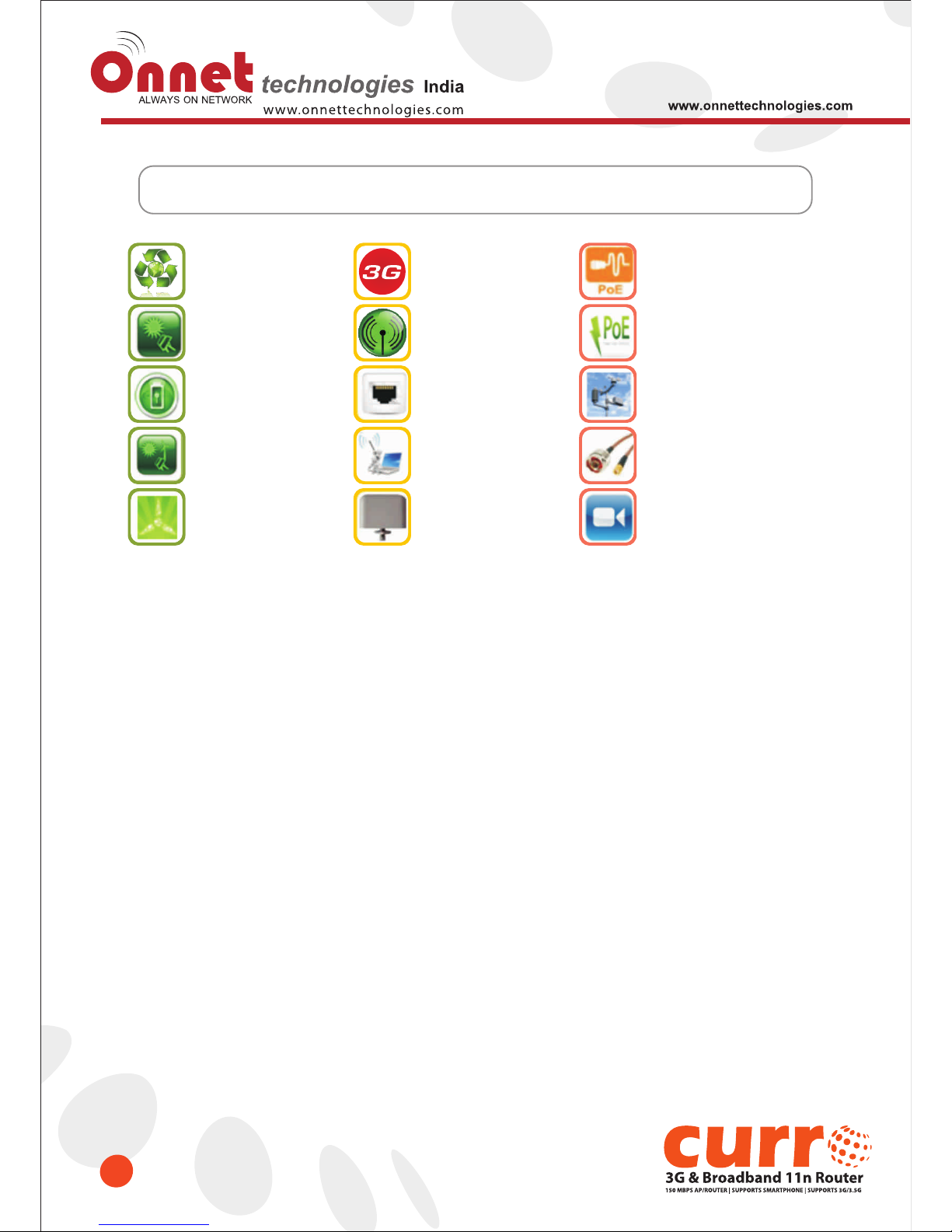
Renewable
Energy
Solar Power
UPS
Wind Power
UPS
Hybrid
Power UPS
1-10 KW
Wind Turbine
3G USB stick
& 3G Wi-Fi routers
Wi-Fi
(Hot Spot)
Indoor LAN
Networking
Outdoor
Wireless
Antenna
POE
Injector / Splitter/X over
Outdoor
POE Switch
Weather
Station (wireless)
RF Cable
Assemblies
IP
Surveillance
Our Solutions
Page 10
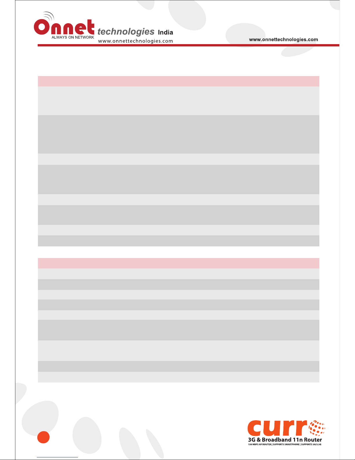
1.4 Specifications
10
NETWORK
Standards
Data Rate
Frequency Range
Mobile (External): HSPA/UMTS/EVDO
WLAN: IEEE 802.11n, 802.11g, 802.11b
WAN: xDSL/Cable Modem
3.5G: Up to 7.2Mbps (Support 3G/3.5G/3.75G)
WiFi: 802.11n (Max 150Mbps), 802.11g (Max 54Mps),
802.11b (Max 11Mbps)
LAN: 802.3/802.3u (10/100Mbps)
2.412~2.484GHz
Wireless Security
WEP 64 or 128 bit/WPA/WPA2/WPA2 Mixed,
WPS (PBC/PIN),
WDS, Multiple APs
Session
20,000
Firewall
MAC Address Filtering, URL Filtering, IP/Port Based Filtering
UPnP, DHCP, DDNS, DNS
Operation Modes
Router, AP, WiFi AP
Network Features
NAT: One-to-Many NAT, Virtual Server, DMZ
HARDWARE
Antenna
LAN
Power Adapter
3 dBi x1 @2.45GHz (Internal)
4x10/100Mbps RJ45, Auto-MDI/MDI-X
DC 5V
WAN
LED Indicator
Operating Temperature
Humidity
1x10/100Mbps RJ45, Auto-MDI/MDI-X
Power, WAN, LAN (1~4), Wireless/WPS,
Operating: 0ºC ~40ºC (32ºF ~104ºF)
Storage: -20ºC ~70ºC (-4ºF ~158ºF)
Operating: 10% to 85% Non-Condensing
Storage: 5% to 90% Non-Condensing
Dimension
118 x 70 x 25 mm (4.65 x 2.75 x 0.98 inch) (Antenna not included)
Management
Web GUI, Firmware upgrade via web
Page 11
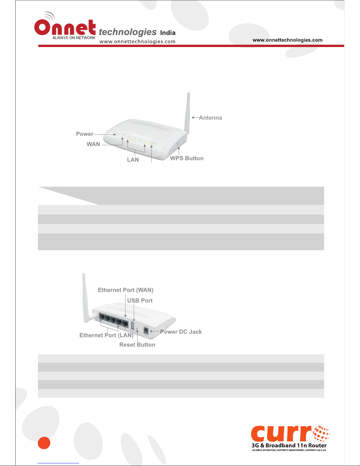
1.5 Product Appearance
11
• FRONT
LED Indicator Status Description:
Solid
Operation OK
Ethernet connected
Ethernet connected
Operation OK
Flashing
Green: Reset / Firmware updates in progress
Transmitting Data
Transmitting Data
Green: Transmitting Data
Orange: WPS enabled
Power
WAN
LAN (1~4)
WIRELESS & WPS
Status
LED Indicator
• REAR
RJ-45 Ethernet 10/100 Ports
RJ-45 Ethernet 10/100 Port
For 3G modem only
Press for back to factory default
DC 5V power in
Ethernet Port (LAN 1~4)
Ethernet Port (WAN)
USB Port
Reset Button
Power DC Jack
Ethernet Port (LAN)Ethernet Port (LAN)
Ethernet Port (WEthernet Port (WAN)AN)
Reset ButtonReset Button
Power DC JackPower DC Jack
USB PortUSB Port
PowerPower
WWANAN
LANLAN
WPS ButtonWPS Button
AntennaAntenna
Page 12
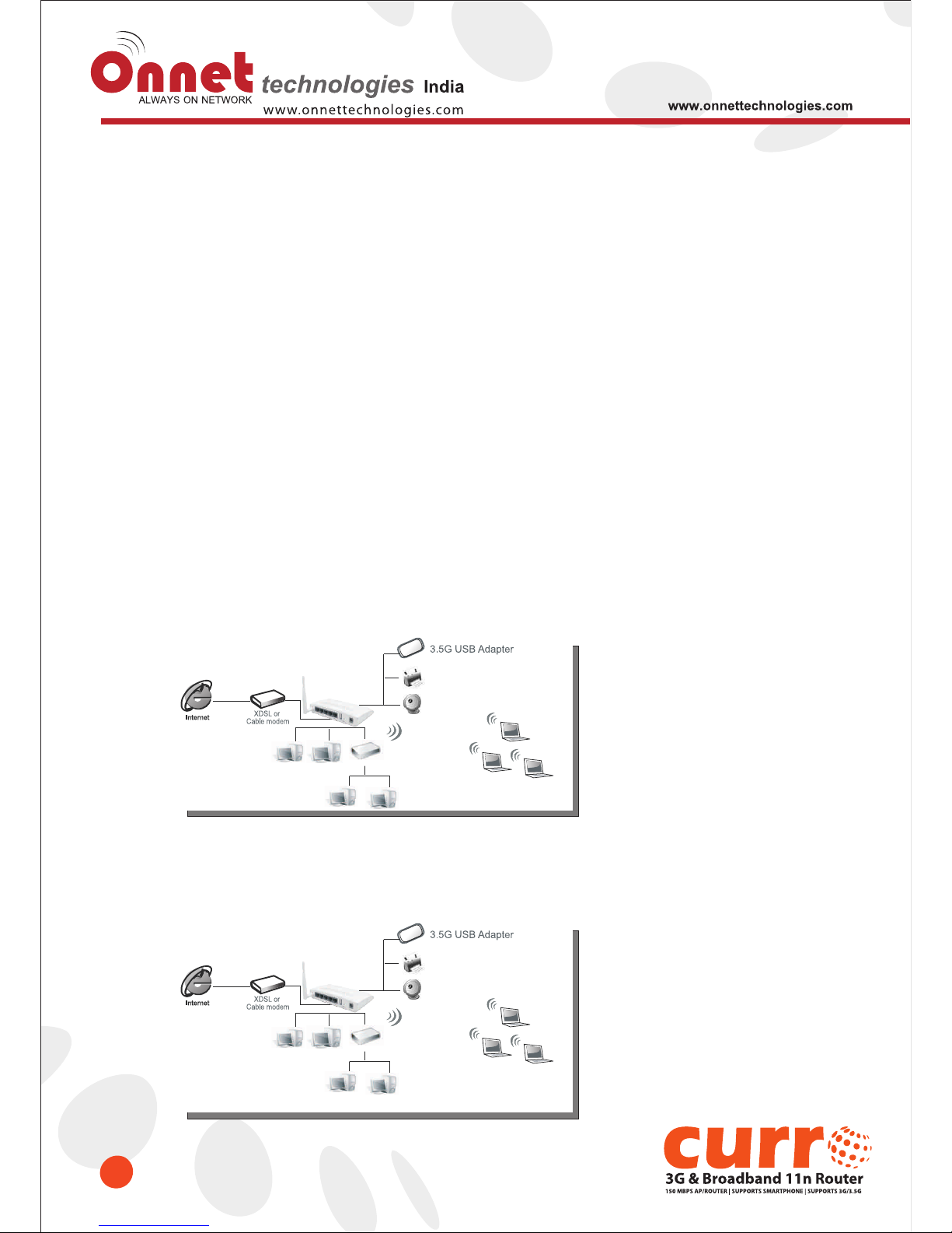
Chapter-2 System and Network Setup
12
The Onnet 3GUSB-4SWRouter is easy to setup and wireless device for various application and environment. It can be
used in conference room, hotels, even in transportation.
To begin with the Onet 3GUSB 4SW Router, you must have the following minimum system requirements. If your system
can’t correspond to the following requirements, you might have some unknown errors on your system.
• Internet Account for XDSL/Cable Modem, broadband or 3G
• One Ethernet (10 BASE-T or 10/100 BASE-TX) network interface card.
• TCP/IP and at least one web browser software installed (E.g.: Internet Explorer 5.0, Netscape Navigator 7.x, Apple
Safari 2.03 or higher version).
• At lease one 802.11g (54Mbps) or one 802.11b (11Mbps) wireless adapter for wireless mobile clients.
• Recommended OS: WinXP, Vista or Win7 / Linux.
2.1 Build Network Connection
Administrator can manage the settings for WAN, LAN, Wireless Network, NTP, password, User Accounts, Firewall,
etc. Please confirmation the network environment or the purpose before setting this product
2.1.1 Router Mode
Switch to router mode through web GUI when the first setup.
2.1.2 AP Mode
Switch to AP mode, if a router is already set up , and you want to make a wireless LAN communication.
Switch or Hub
Switch or Hub
Page 13
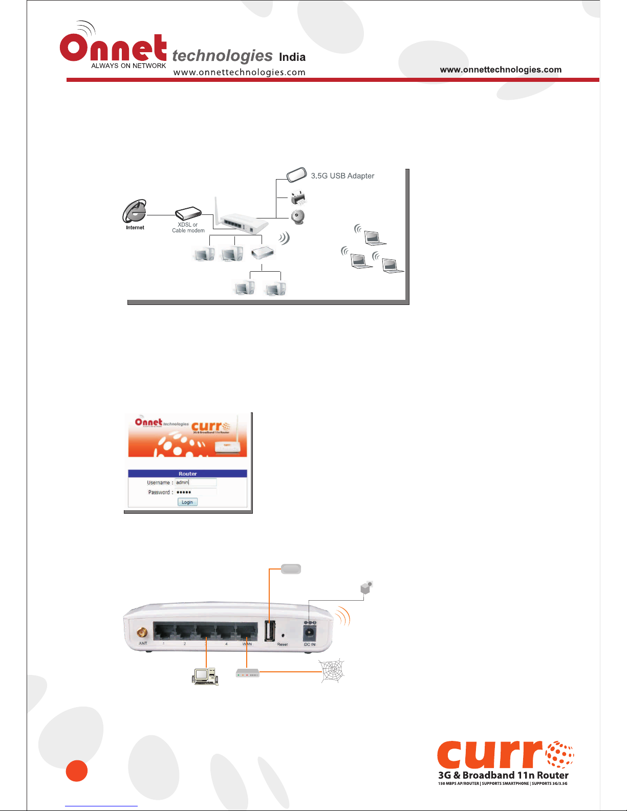
13
2.1.3 Wi-Fi Mode
Switch to WiFi AP Mode when you connect to the internet wirelessly through PC and wireless device without
wireless LAN function equipped.
2.2 Connecting Onnet 3GUSB-4SWRouter
Prepare the followings before the connection:
• PC or Notebook for setup
• Ethernet cable or 3/3.5G modem
1. Make sure you are under “Router Mode”.
2. Connect Onet 3GUSB-4SWRouter to xDSL/ Cable modem with the Ethernet cable, WAN to LAN.
Ethernet Cable
Internet
PC
xDSL/Cable
Modem
xDSL/Cable Line
3.5 G Modem
Power Adapter
Switch or Hub
Page 14
14
3. Turn ON your computer
2.3 Network setup
After the network connection is built, the next step is setup the router with proper network parameters, so it can work
properly in your network environment. Before you connect to the wireless router and start configuration procedures,
your computer must be able to get an IP address from the wireless router automatically (use dynamic IP address). If
it’s set to use static IP address, or you’re unsure, please follow the below instructions to configure your computer with
dynamic IP address:
If the operating system of your computer is….
Windows 2000 - please go to section 2.3.1
Windows XP - please go to section 2.3.2
Windows Vista/Win7 - please go to section 2.3.3
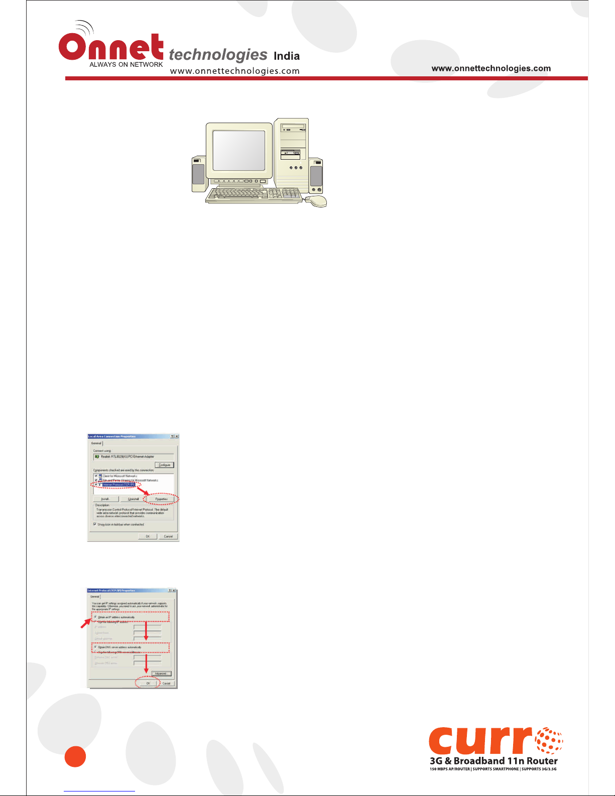
2.3.1Windows 2000
Click “Start” button (it should be located at lower-left corner of your computer), then click control panel. Double-click
Network and Dial-up Connections icon, double click Local Area Connection, and Local Area Connection Properties
window will appear. Select “Internet Protocol (TCP/IP)”, then click “Properties”.
1. Select “Obtain an IP address automatically” and “Obtain DNS server address automatically”, then click “OK”.
Page 15
15
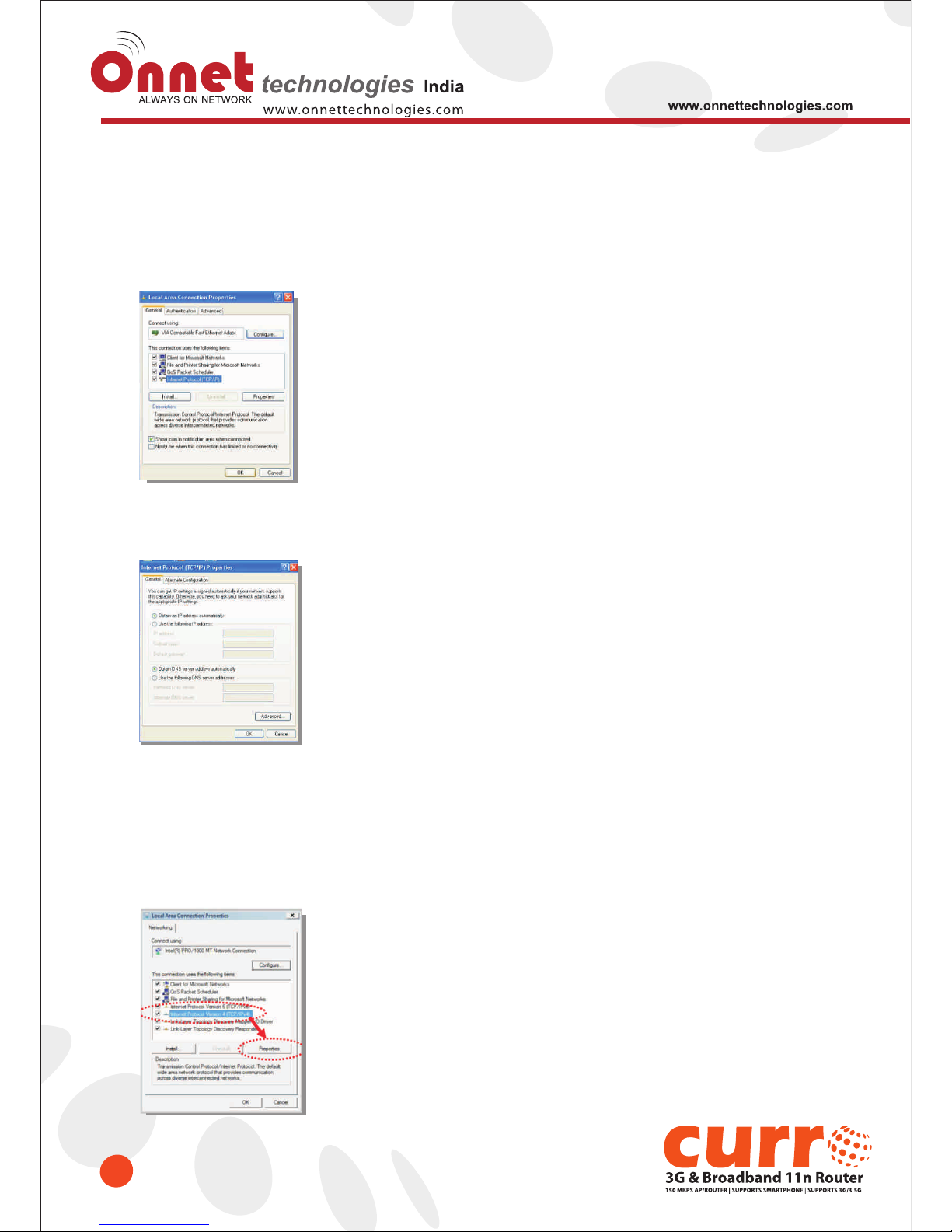
2.3.2 Windows XP
1. Click “Start” button (it should be located at lower-left corner of your computer), then click control panel. Double-click
Network and Internet Connections icon, click Network Connections, then double-click Local Area Connection,
Local Area Connection Status window will appear, and then click “Properties”.
2. Select “Obtain an IP address automatically” and “Obtain DNS server address automatically”, then click “OK”.
2.3.3 Windows Vista / Windows 7
1. Click “Start” button (it should be located at lower-left corner of your computer), then click control panel. Click View
Network Status and Tasks, and then click Manage Network Connections. Right-click Local Area Network, then
select “Properties”. Local Area Connection Properties window will appear, select “Internet Protocol Version 4 (TCP
/ IPv4)”, and then click “Properties”.
Page 16
16
2.4 Router IP Address Lookup
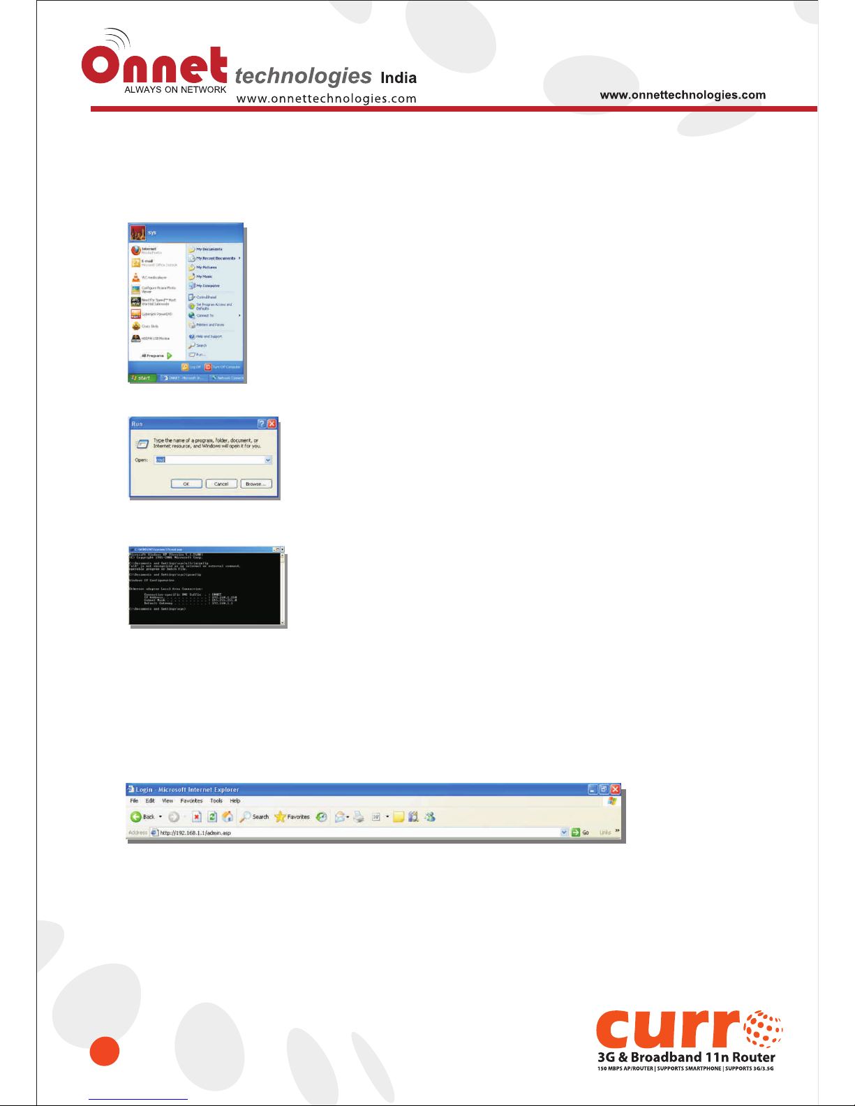
1. After the IP address setup is completed, please clicks “start” → “run” at the bottom-lower corner of your desktop:
2. In put "cmd" and then click "OK"
Input “ipconfig”, then press “Enter” key. Please check the IP address followed by “Default Gateway” (In this
example, the gateway IP address of router is 192.168.1.1)
2.4.1 Log into Web GUI
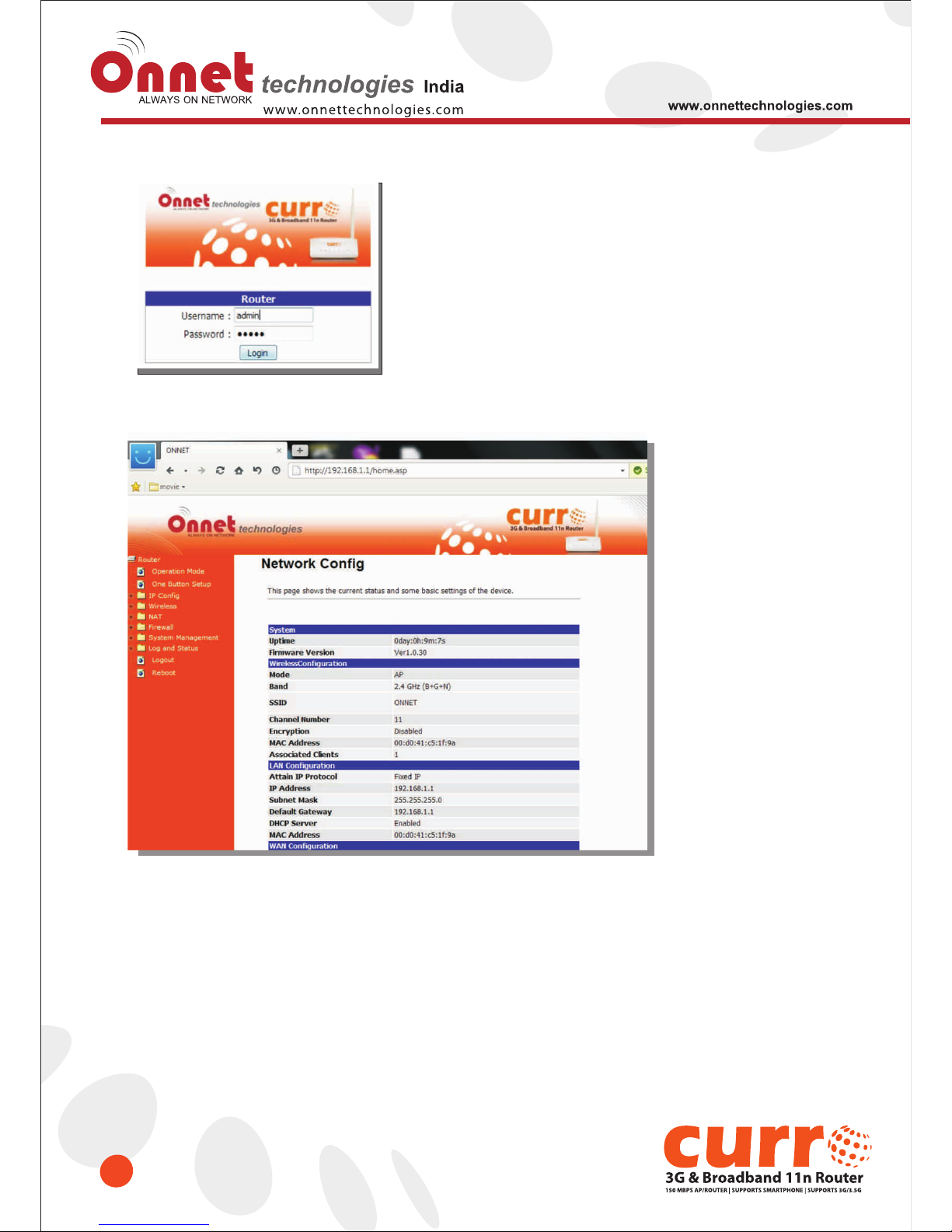
After your computer obtains an IP address from wireless router, please start your web browser, and input the IP
address of the wireless router in address bar, and the following message should be shown. Please click “onnet” to
login the Onet 3GUSB-4SWRouter.
Enter the User name and Password in to the blank and then Click Login. The default values for User Name and
Password are onnet (all in lowercase letters).
NOTE: If the IP address of Gateway is not displayed, or the address followed by 'IP Address' begins with
“169.x.x.x”, please recheck network connection between your computer and router, and / or go to the
beginning of this chapter, to recheck every step of network setup procedure.
Page 17
17
Page 18

Chapter-3 Internet Connection
18
This Chapter describes how to setup Onet 3GUSB-4SWRouter to the internet. The Onet 3GUSB-4SWRouter is
delivered with the following factory default parameters.
Default IP address: 192.168.1.1 (Router Mode)
192.168.1.254 (AP Mode)
192.168.1.254 (WiFi AP Mode)
Default IP subnet mask: 255.255.255.0
Web login user name: onnet
Web login password: onet
3.1 Plug and Play
The Onet 3GUSB-4SWRouter supports three types of Internet connection method: 3G/3.5G modem card, wire or
wireless connection via xDSL/Cable modem. Just connect the 3G/3.5G modem card or Ethernet cable to Onet
3GUSB-4SWRouter, the router will recognize it automatically.
3.1.1 SmartPhone /iPhone Intternet sharing plug and play
With Onet 3GUSB-4SWRouter, you can build an instant 802.11n wireless broadband sharing environment with
your iPhone, Windows Mobile or Google smartphone. During the time you can still answer calls, send SMS and
charge your phone.
Page 19
19
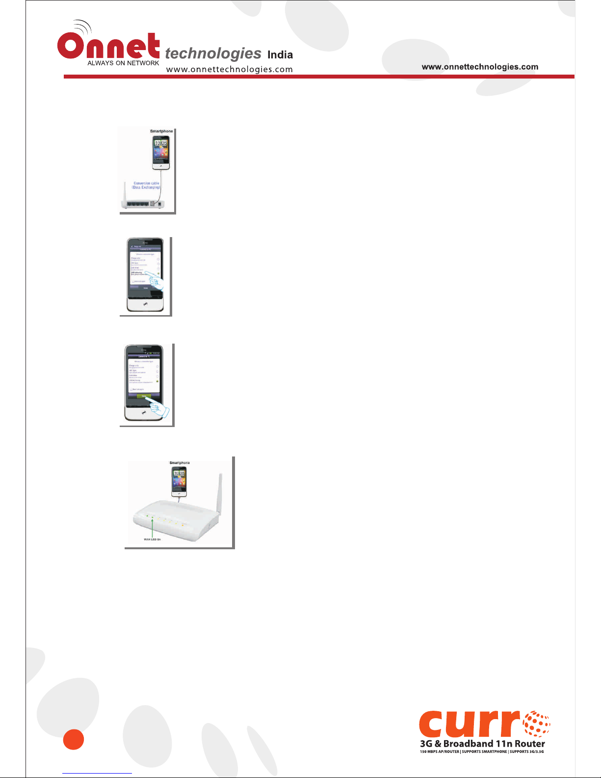
Step 1. Connect iPhone/Smartphone with Onet 3GUSB-4SWRouter via USB cable.
Step 2. Select “USB Tethering” as connection type.
Step 3. Click on “Done”.
Step 4. Wait few seconds for pairing. When WAN LED on, the Internet is ready to access.
Note: 1. iPhone:
2. Google Android Phone:
(1) Due to difference in 3G service bundled in various carriers, please check your 3G service supports Internet
tethering.
(2) Enable Internet Tethering on iPhone 3GS / iPhone 4, and set up the screen lock to never to prevent the sharing is
interrupted unexpected by the iPhone screen lock feature.
please turn on "USB modem mode” when connecting router.
Page 20
20
3.2 Router Mode- Using as a broadband router
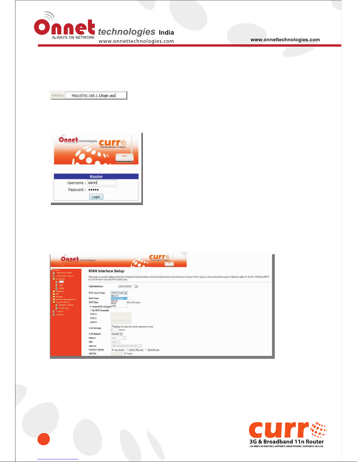
1. Open a Web browser, and enter http://192.168.1.1 (Default Gateway) into the blank.
2. Enter the User name and Password in to the blank and then Click Login. The default values for User Name and
Password are onnet (all in lowercase letters).
3.2.1 WAN Interface- Ethernet Port
The WAN access type is dependent on the service that you contract with the provider. The Onet 3GUSB-
4SWRouter provides five selections for the WAN access type, Static IP, DHCP Client, PPPoE, PPTP, L2TP. Check
with your ISP if you don’t know the WAN type.
Page 21

21
3.2.1.1 Static IP
Select WAN under the IP Config menu, and choose Ethernet Port for the WAN Interface. Its associated setting
will show up.
Item
WAN Access Type
IP Address
Subnet Mask
Default Gateway
DNS
Clone Mac Address
Apply Change & Reset
Description
Select “Static IP”
Enter the IP address which is provided by your ISP.
Please enter the Subnet Mask address
Input ISP Default Gateway Address, .
Input DNS information which is provided by your ISP
Some ISPs require MAC address registration. In this case, enter the MAC
address registered to the provider to "Clone MAC Address"
Click on Apply Change to save the setting date, or you may click on
Reset to clear all the input data.
Page 22
22
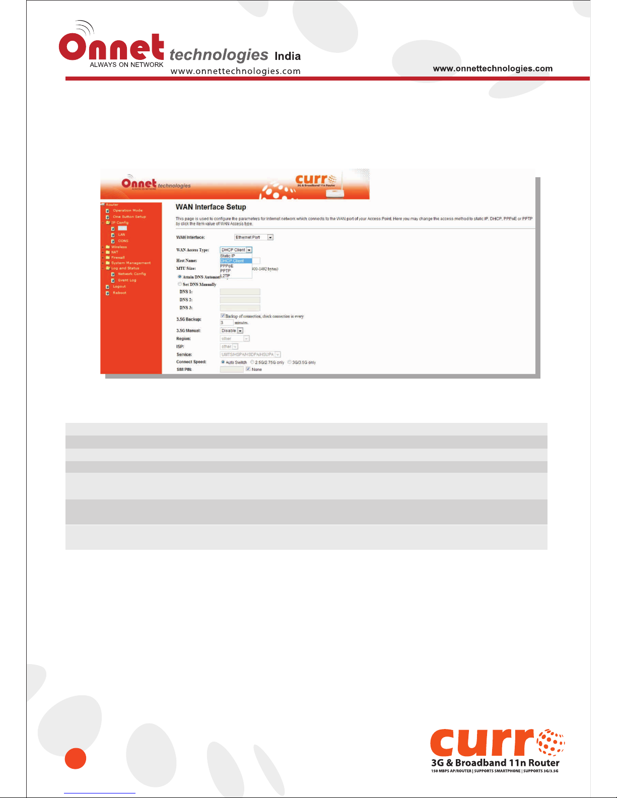
3.2.1.2 DHCP Client
Select WAN under the IP Config menu, and choose Ethernet Port for the WAN Interface. Its associated setting
will show up.
Item
Host Name
DNS
Clone Mac Address
Apply Change & Reset
WAN Access Type
Description
You can keep the default as the host name, or input a specific name if
required by your ISP.
Select Attain DNS Automatically. Or select Set DNS Manually, if you want to
specify the DNS, and enter the DNS provided by your ISP in DNS 1 2 3.
Some ISPs require MAC address registration. In this case, enter the MAC address
registered to the provider to "Clone MAC Address"
Click on Apply Change to save the setting date, or you may click on
Reset to clear all the input data.
Select "DHCP Client"
Page 23
23
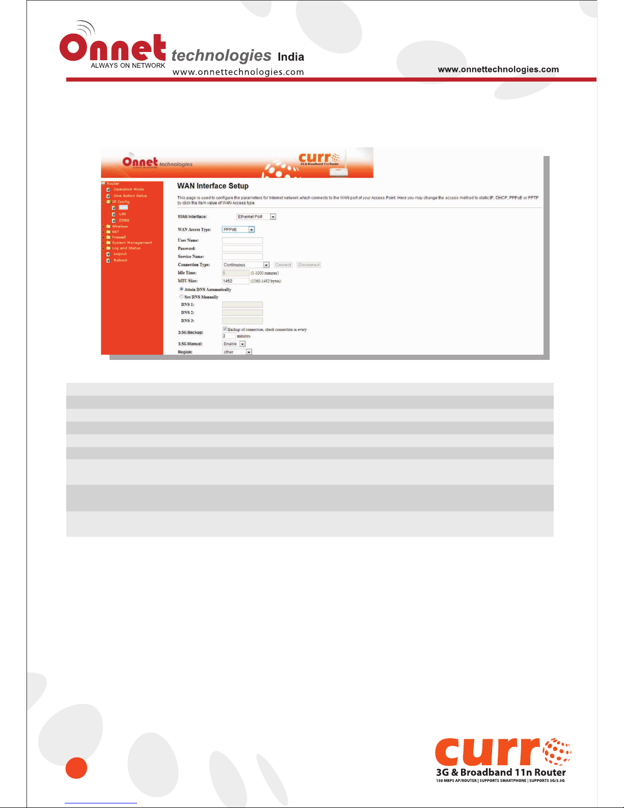
3.2.1.3 PPPoE
Item
WAN Access Type
User Name
Password
Service Name
Connection Type
DNS
Clone Mac Address
Apply Change & Reset
Description
Select "PPPoE"
Input your user name provided by your ISP. If you don’t know, please check with your ISP.
Input the password provided by your ISP.
Input the service name provided by your ISP.
Three types for select: Continues, Connect on Demand, and Manual.
Select Attain DNS Automatically. Or select Set DNS Manually, if you want to specify the
DNS, and enter the DNS provided by your ISP in DNS 1 2 3.
Some ISPs require MAC address registration. In this case, enter the MAC address
registered to the provider to "Clone MAC Address"
Click on Apply Change to save the setting date, or you may click on Reset to clear all
the input data.
Page 24
24
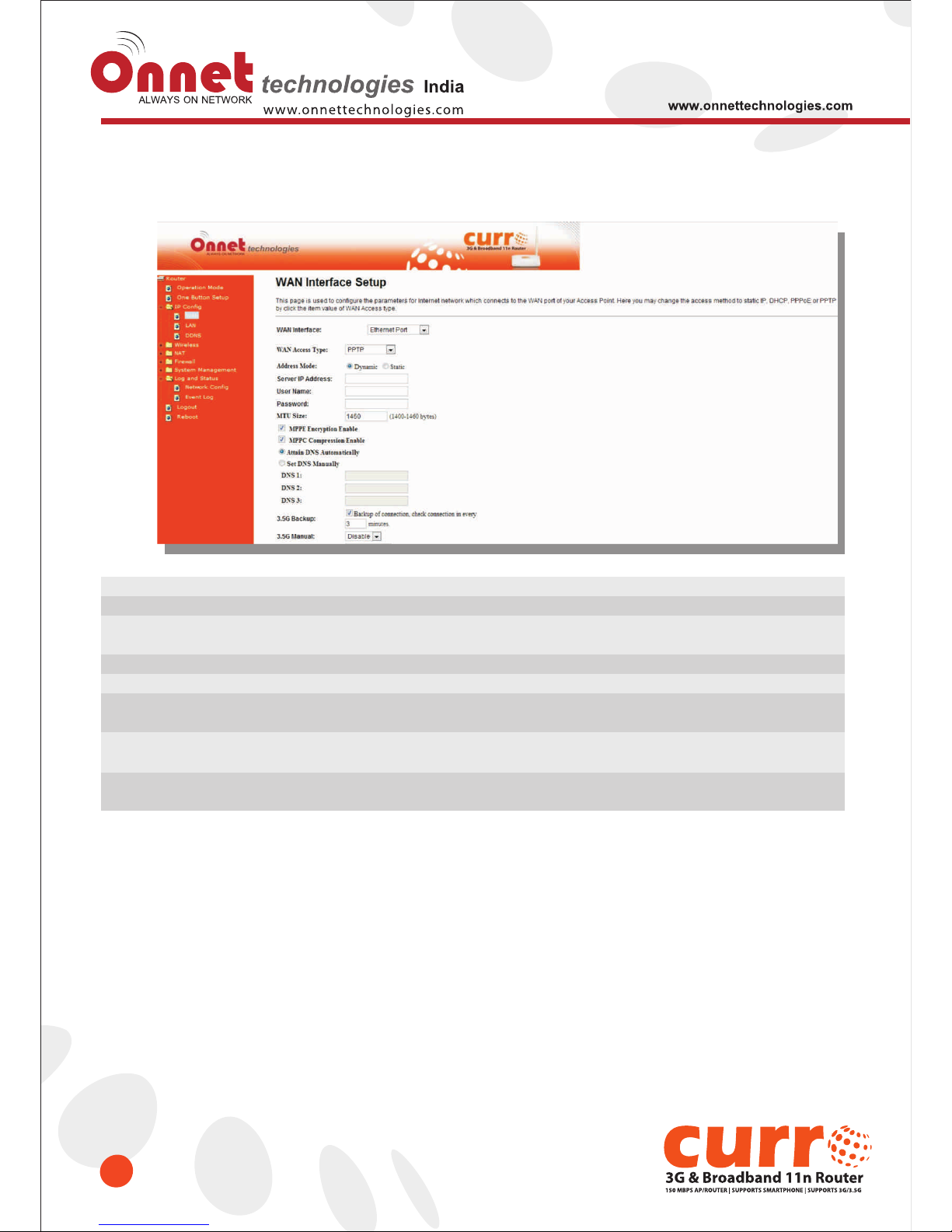
3.2.1.4 PPTP
Item
WAN Access Type
Server IP Address
User Name
Password
DNS
Clone Mac Address
Apply Change & Reset
Description
Select "PPTP"
Input your server IP address provided by your ISP. If you don’t know,
please check with your ISP.
Input PPTP account provided by your ISP.
Input the password provided by your ISP.
Select Attain DNS Automatically. Or select Set DNS Manually, if you want to specify the
DNS, and enter the DNS provided by your ISP in DNS 1 2 3.
Some ISPs require MAC address registration. In this case, enter the MAC address
registered to the provider to "Clone MAC Address"
Click on Apply Change to save the setting date, or you may click on Reset to clear
all the input data.
Page 25
25
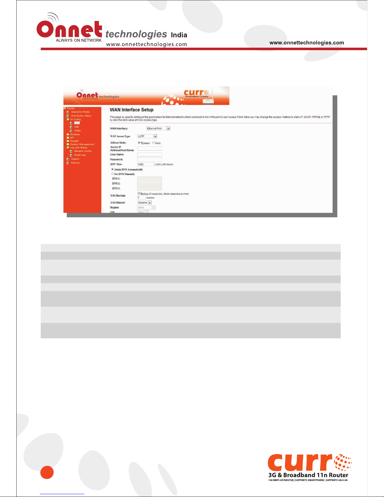
3.2.1.5 L2TP
Item
WAN Access Type
Server IP Address /
Host Name
User Name
Password
DNS
Clone Mac Address
Apply Change & Reset
Description
Select "PPTP"
Input your server IP address or Host Name provided by your ISP.
If you don’t know, please check with your ISP.
Input PPTP account provided by your ISP.
Input the password provided by your ISP.
Select Attain DNS Automatically. Or select Set DNS Manually, if you want to specify
the DNS, and enter the DNS provided by your ISP in DNS 1 2 3.
Some ISPs require MAC address registration. In this case, enter the MAC address
registered to the provider to "Clone MAC Address"
Click on Apply Change to save the setting date, or you may click on Reset to
clear all the input data.
Page 26
26
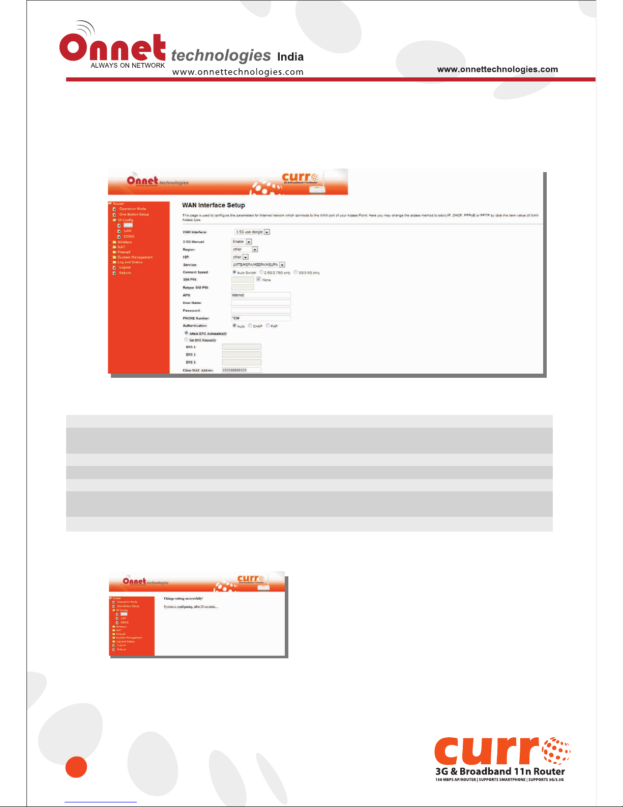
3.2.2 WAN Interface- 3.5G USB dongle
Select WAN under the IP Config menu, and choose 3.5G usb dongle for the WAN Interface. Its associated
setting will show as below.
Item
APN
(Access Point Name)
User Name
Password
Phone Number
Always / Dial on
demand
Apply Change
Description
Enter the access point name. If you do not know the setting information for APN,
check with your 3.5G service provider.
Enter the User Name supplied by the provider.
Enter the password supplied by the provider.
Enter the subscribing access point's phone number.
If your 3G USB adapter is a pay-as-you-go plan base, select “Dial on demand” and
disconnect the connection when you don't use the internet.
Click “Finish” to complete the setting
Rebooting of this product is on now. Please wait for a while.
Page 27
27
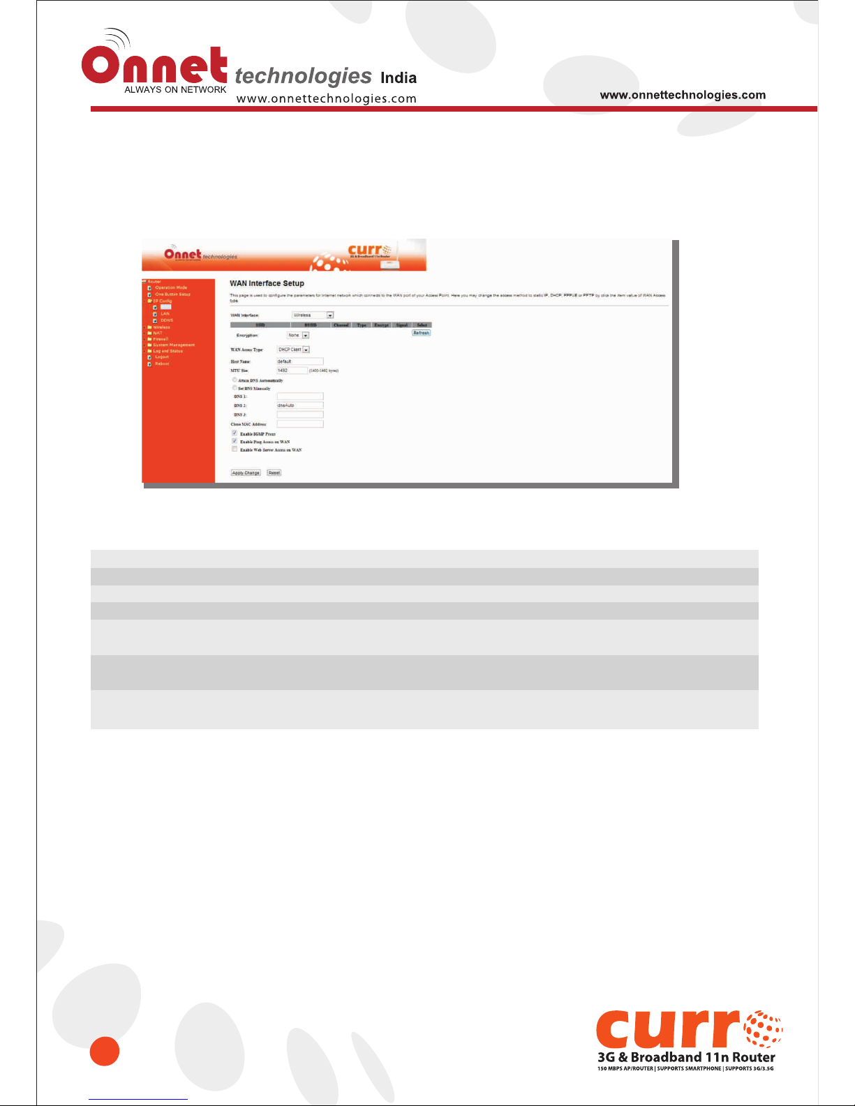
3.2.3 WAN Interface- Wireless
Select WAN under the IP Config menu, and choose wireless for the WAN Interface. Its associated setting will
show as below.
Item
Refresh
Encryption type
WAN Access Type
DNS
Clone Mac Address
Apply Change & Reset
Description
You can see a list of available Wireless networks. Select the preferred one.
Select the Encryption type form the drop-down list.
Select Static IP, DHCP, PPPoE, PPTP or L2TP.
Select Attain DNS Automatically. Or select Set DNS Manually, if you want to specify
the DNS, and enter the DNS provided by your ISP in DNS 1 2 3.
Some ISPs require MAC address registration. In this case, enter the MAC address
registered to the provider to "Clone MAC Address"
Click on Apply Change to save the setting date, or you may click on Reset to
clear all the input data.
Page 28
28
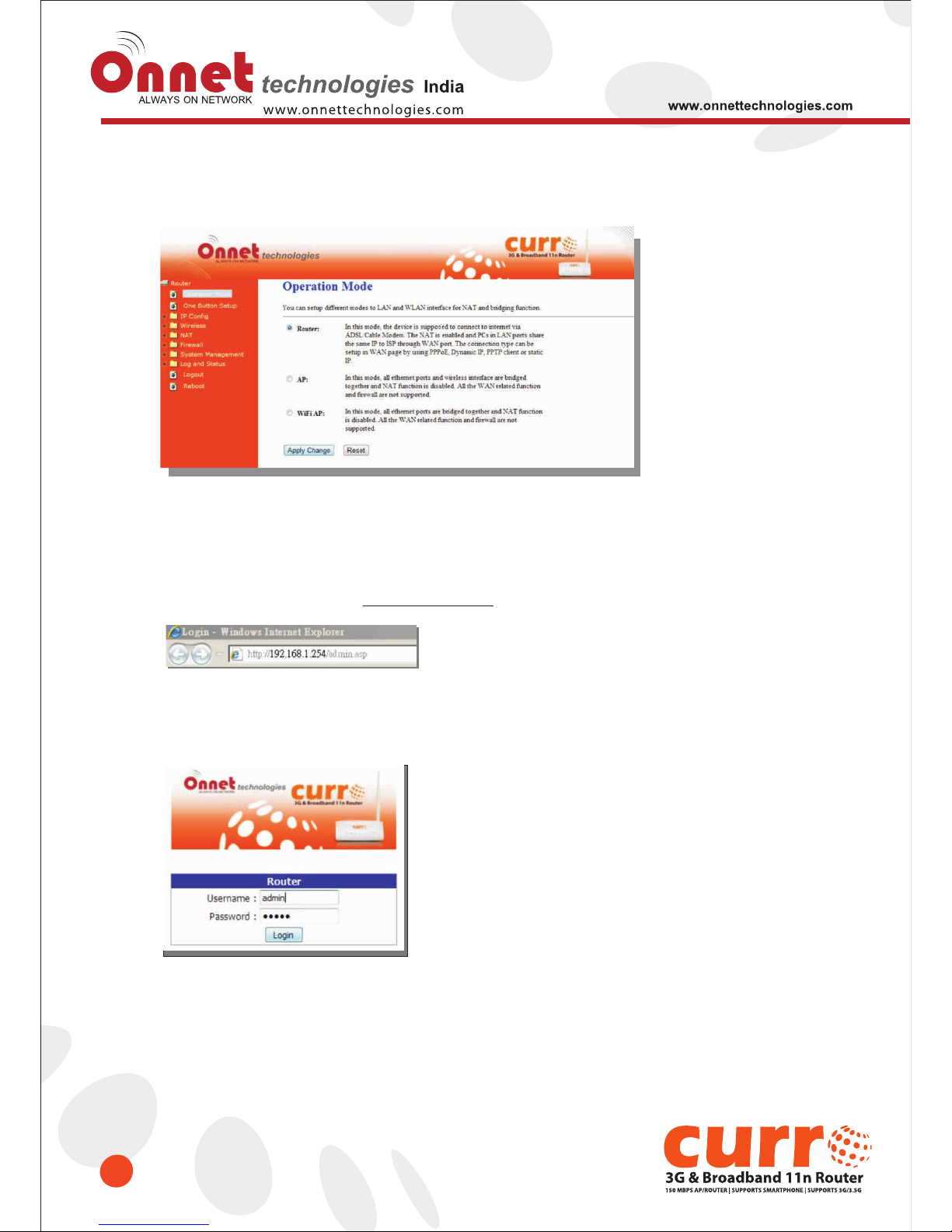
3.3 AP Mode-Using as a Access Point
Make sure to shift the mode into AP Mode.
When this product is used as an access point, the IP address has to be changed. The default IP under AP mode
is 192.168.1.254.
1. Open a Web browser, and enter http://192.168.1.254 (Default Gateway) into the blank.
2. Enter the User name and Password in to the blank and then Click Login. The default values for User Name and
Password are onnet (all in lowercase letters).
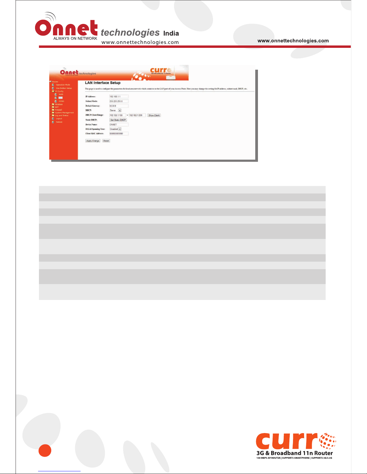
Select LAN under the IP Config menu
Page 29
29
Item
IP Address
Subnet Mask
Default Gateway
DHCP
DHCP Client Range
Static DHCP
Device Name
802.1d Spanning Tree
Clone Mac Address
Apply Change & Reset
Description
The default IP address is 192.168.1.254
Enter the Subnet Mask address
Enter the Default Gateway address for LAN interfaces
Select DHCP type: Client, Disable, or Server under different environment.
When enable DHCP server, you can fill in the start and end IP address;
client will be assigned an IP address from the range.
When enable DHCP server, you can set static DHCP to a network device
with specified MAC address
Input a name for this router.
Disable or Enable the 802.1d Spanning Tree Protocol (STP)
Some ISPs require MAC address registration. In this case, enter the MAC address
registered to the provider to "Clone MAC Address"
Click on Apply Change to save the setting date, or you may click on
Reset to clear all the input data.
Page 30
30
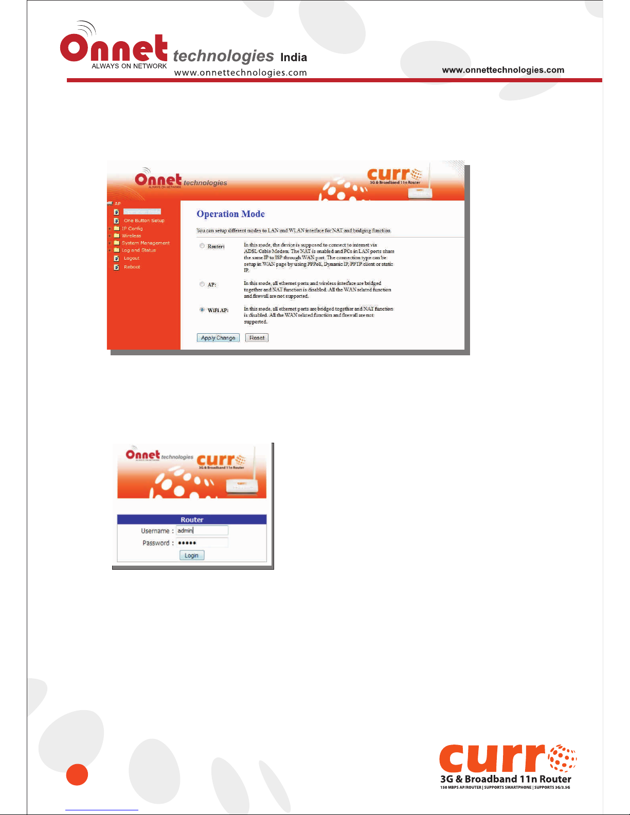
3.4 WiFi AP Mode- Using as a Network Converter
Ensure to shift the mode into WiFi AP Mode.
The default gateway is http://192.168.1.254 and for User Name and Password are onnet (all in lowercase
letters). Click Login to enter.
Page 31
31
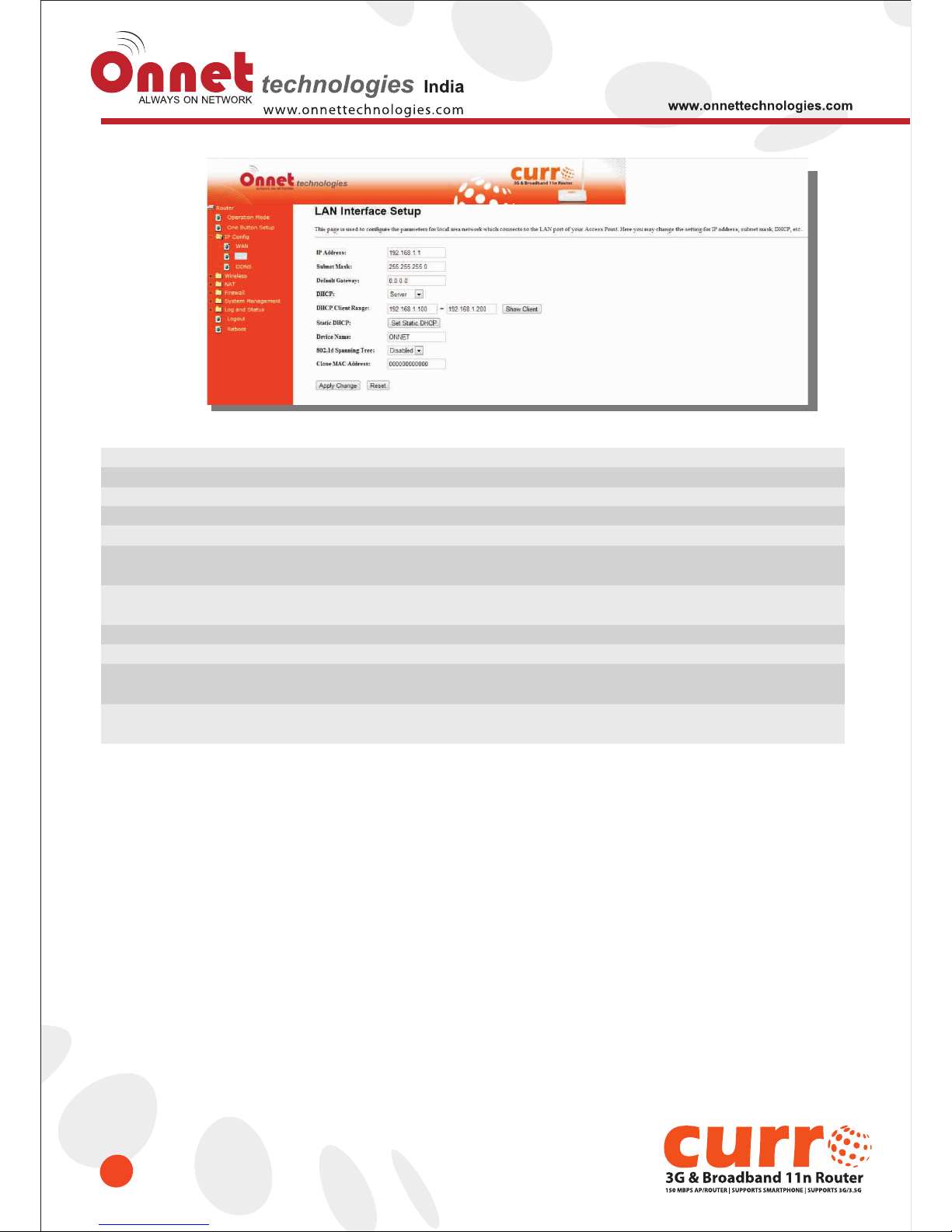
Item
IP Address
Subnet Mask
Default Gateway
DHCP
DHCP Client Range
Static DHCP
Device Name
802.1d Spanning Tree
Clone Mac Address
Apply Change & Reset
Description
The default IP address is 192.168.1.254
Enter the Subnet Mask address
Enter the Default Gateway address for LAN interfaces
Select DHCP type: Client, Disable, or Server under different environment.
When enable DHCP server, you can fill in the start and end IP address;
client will be assigned an IP address from the range.
When enable DHCP server, you can set static DHCP to a network device with
specified MAC address
Input a name for this router.
Disable or Enable the 802.1d Spanning Tree Protocol (STP)
Some ISPs require MAC address registration. In this case, enter the MAC address
registered to the provider to "Clone MAC Address"
Click on Apply Change to save the setting date, or you may click on
Reset to clear all the input data.
Page 32
Chapter-4 Wireless Setup
32
4.1 Wireless Setup
There are two ways to setup wireless LAN with Onet 3GUSB-4SWRouter. You can use either way to setup Wireless LAN.
4.1.1 Setup Wireless LAN by WPS button
You can setup wireless LAN easily by using the WPS button if both WLAN router and the WLAN adapter (client)
are WPS supported. Before starting the setup, please check the foll things below:
• Prepare to connect for Internet connection with Onet 3GUSB-4SWRouter
• The WLAN adapter is finished installation and plug in your computer/ laptop.
There are two ways to setup a wireless LAN between Onet 3GUSB-4SWRouter and your wireless adapter:
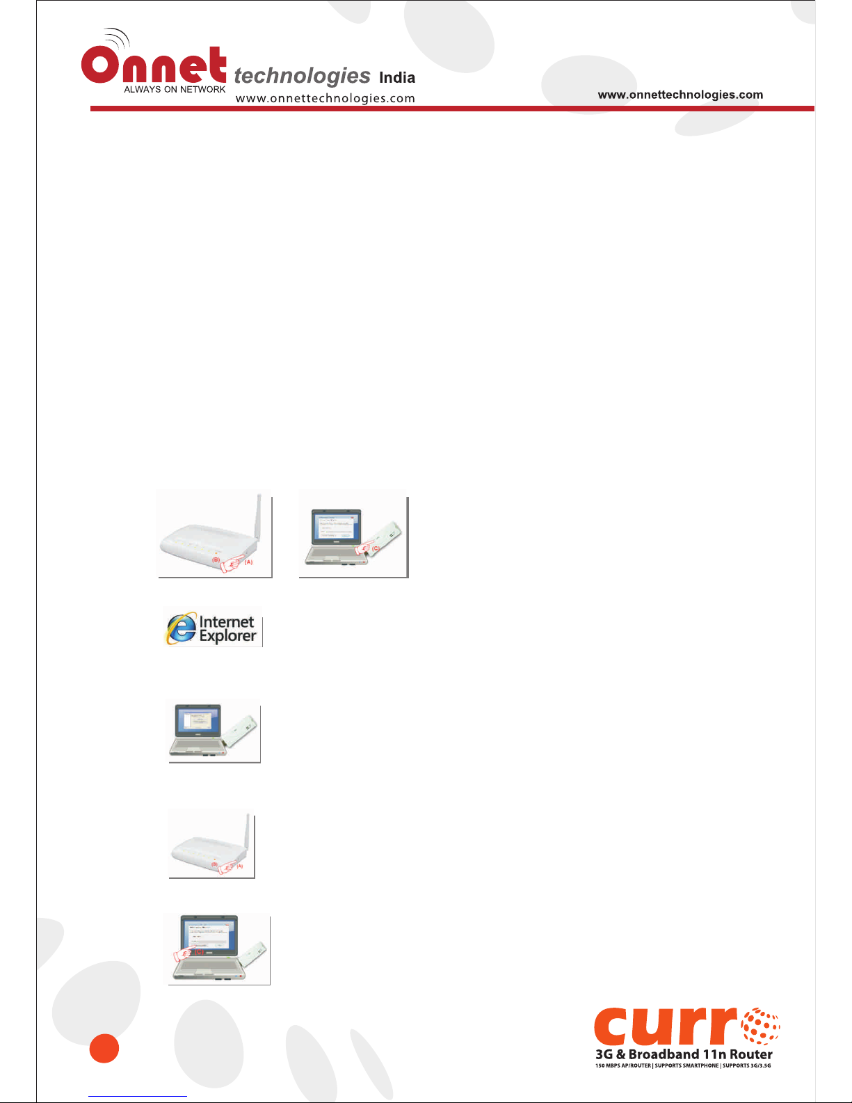
1. Setup with WPS button, if your wireless adapter has a physical WPS button.
(1) Press the WPS button (A) from Onet 3GUSB-4SWRouter and wait for Wireless/WPS LED light (B) changed
into orange.
(2) Press the WPS button (C) from the adapter until the setup window shows up.
(3) Open a web browser to check the internet connection.
(4) Setup without WPS button if you wireless adapter has only virtual WPS function.
(5) Open Wireless adapter utility.
(6) Press the WPS button (A) from Onet 3GUSB-4SWRouter and wait for Wireless/WPS LED light (B) changed
into orange.
(7) Back to the WLAN adapter utility and click its “PBC” (C) button.
Page 33
33
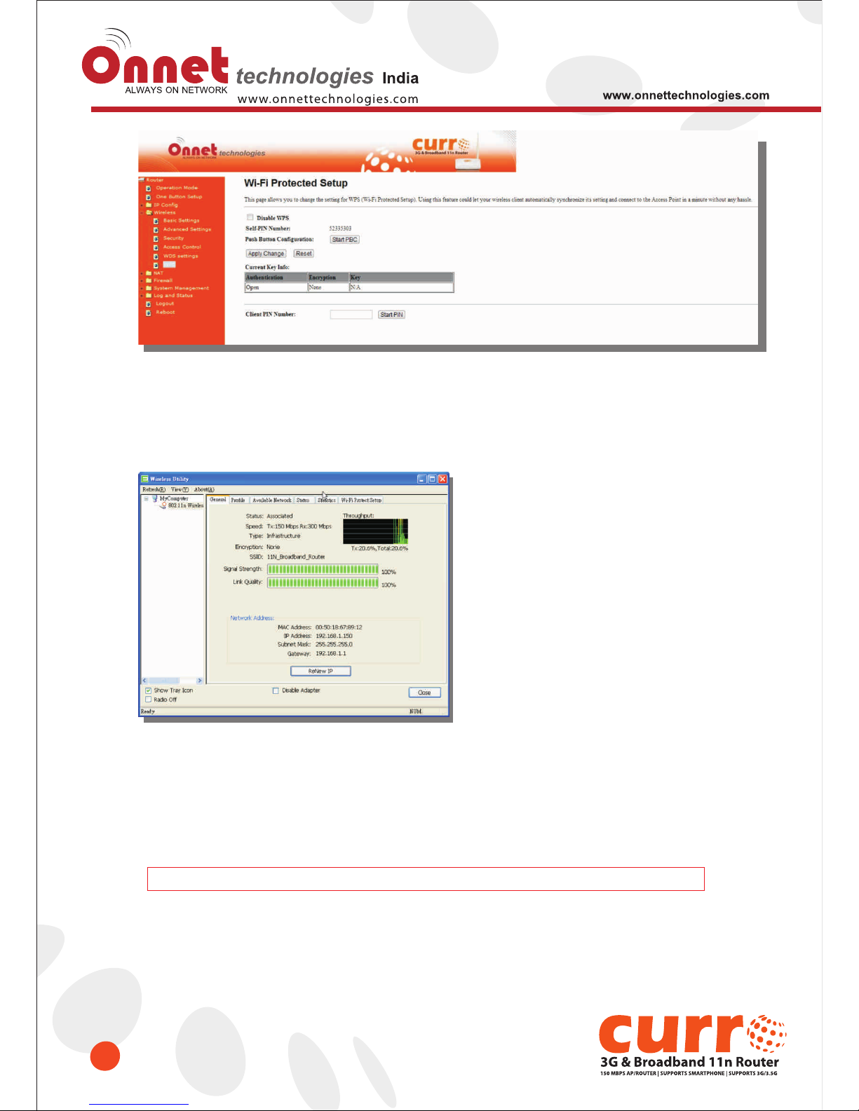
The utility will start searching the destination connection.
(8) Confirm the information form the Utility
(9) After completing the WPS setup. Please confirm that it can be connected to the Internet.
Note: The setup image might be some differences when using other branded Adapter.
Page 34
34
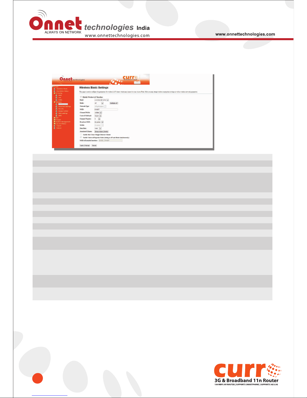
4.1.2 Wireless Basic Setup from Web GUI
The Wireless Basic Settings include Band, Mode, SSID, Channel Number and other wireless settings.
Item
Disable Wireless LAN Interface
Band
Mode
SSID
Channel Width
Control Sideband
Channel Number
Broadband SSID
Data Rate
Associate Clients
Enable MAC Clone
(Single Ethernet Client)
Enable Universal Repeater Mode
(Acting as AP and Client
simultaneously)
SSID of Extended Interface
Apply Change & Reset
Description
Turn off the wireless service.
Select the frequency. It has 6 options: 2.4 GHz (B/G/N/B+G/G+N/B+G+N).
Select the mode. It has 3 modes to select: (AP, Client, WDS, AP+WDS).
Multiple AP: Please check Section 4.1.2.1.
* In Wi-Fi AP mode only support Client mode.
Service Set identifier, users can define to any or keep as default.
Please select the channel width, it has 2 options: 20MHZ, and 40MHZ.
Enable this function will control your router use lower or upper channel.
Please select the channel; it has Auto, 1, 2~11 or 13 options.
User may choose to enable Broadcast SSID or not.
Please select the data transmission rate.
Check the AP connectors and the Wireless connecting status.
Clone the MAC address for ISP to identify.
Allow to equip with the wireless way conjunction upper level, provide the
bottom layer user link in wireless and wired mode in the meantime.
(The IP that bottom layer obtains is from upper level.)
Please also check Section 4.1.2.2
While linking the upper level device in wireless mode, you can set SSID to
give the bottom layer user search.
Click on Apply Change to save the setting date, or you may click on
Reset to clear all the input data.
* Under WiFi AP Mode, there are 2 options of Network type: Infrastructure or Ad hoc. Select Infrastructure if connecting
to a wireless router or access point. Select Ad hoc if connecting directly to another wireless adapter.
Page 35
35
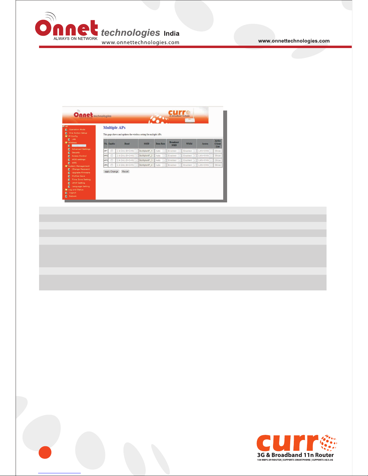
4.1.2.1 Multiple APs
The Onet 3GUSB-4SWRouter can register up to 4 SSIDs (wireless LAN group). It can be used as if there are
multiple wireless LAN access points with one product. Each SSID could be set with different data rate, WMM
and access type.
Item
Enable
Band
SSID
Data Rate
Access
Active Client List
Apply Change & Reset
Description
Enable or disable the service.
Select the frequency.
Enter the SSID
Select the data transmission rate.
Enable this function can let clients use two access types:
a. LAN+WAN: the client can access to the Internet and access in the router’s GUI.
b. WAN: the client can only access to the Internet.
Display the properties of the client which is connecting successfully.
Click on Apply Change to save the setting date, or you may click on
Reset to clear all the input data.
Page 36
36
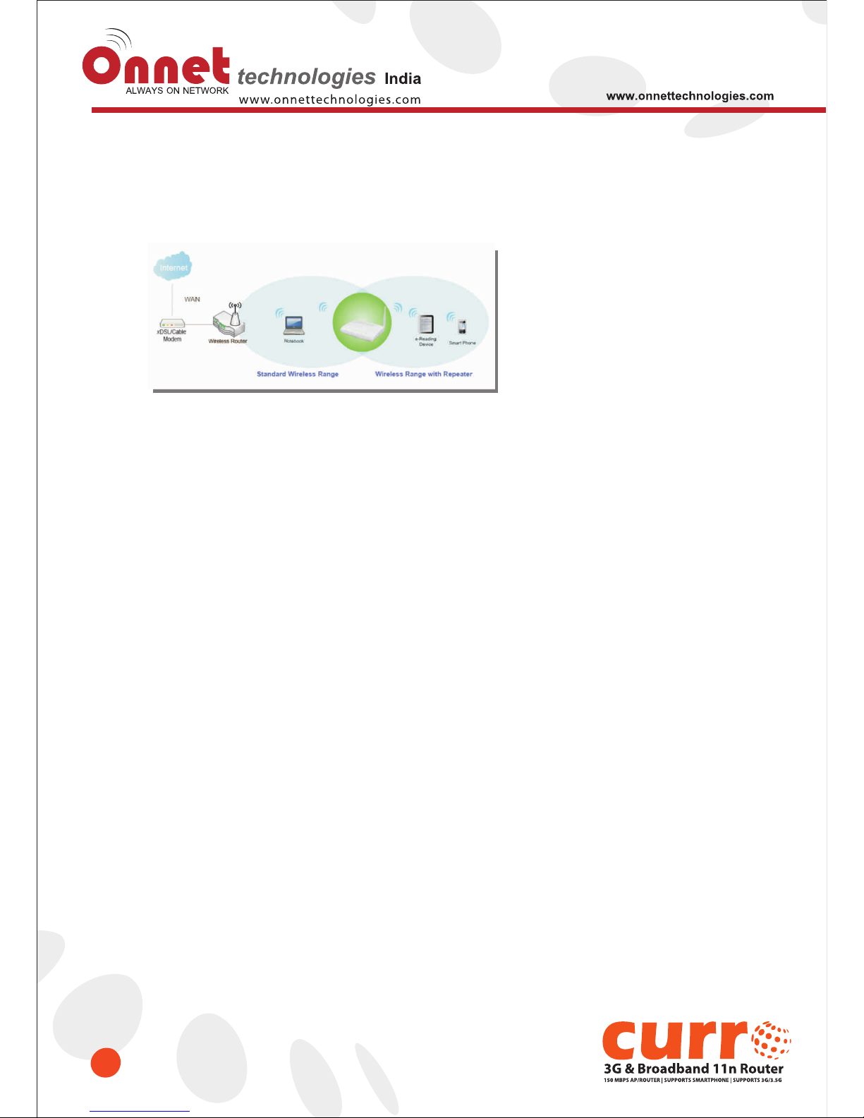
4.1.2.2 Enable Universal Repeater Mode
The router can act as Station and AP at the same time. It can use Station function to connect to a Root AP and
use AP function to service all wireless stations within its coverage.
Example: When users enable the Universal Repeater to connect to the upper level device, please fill in the
upper level device‟ s channel and SSID. Click on Apply Changes to save the settings.
Page 37
37
(Please disable the DHCP service first)
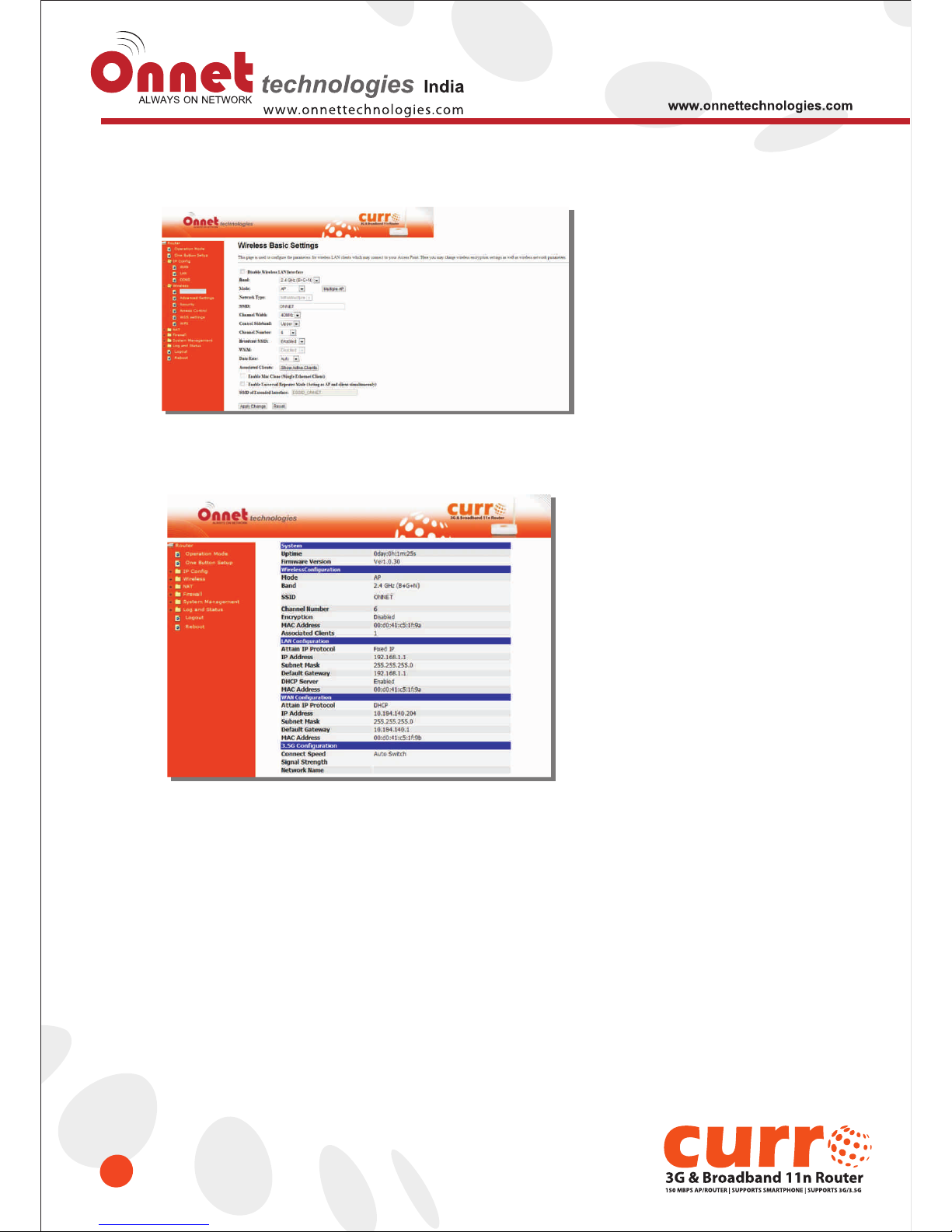
Users can use the Network Configuration page to check the information about “Wireless Repeater Interface
Configuration”.
Page 38
38
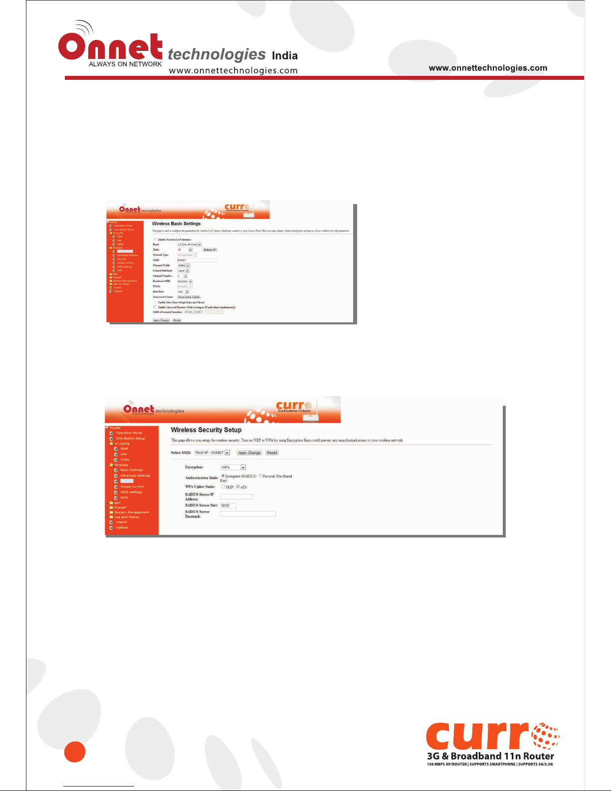
4.2 Wireless Security Setup
Here users define the security type and level of the wireless network. Selecting different methods provides
different levels of security. Please note that using any encryption may cause a significant degradation of data
throughput on the wireless link. There are five Encryption types supported: “None”, “WEP”, “WPA (TKIP)”,
”WPA2(AES)”, and “WPA2 Mixed”. Enabling WEP can protect your data from eavesdroppers. If you do not need
this feature, select “None” to skip the following setting.
1. Encryption- WEP Key
(1) Set WEP Key: This section provides 64bit and 128bit WEP encryptions and two different shared key formats
(ASCII and Hex) for wireless network.
(2) 802.1x Authentication
It is a safety system by using authentication to protect your wireless network.
Page 39
39
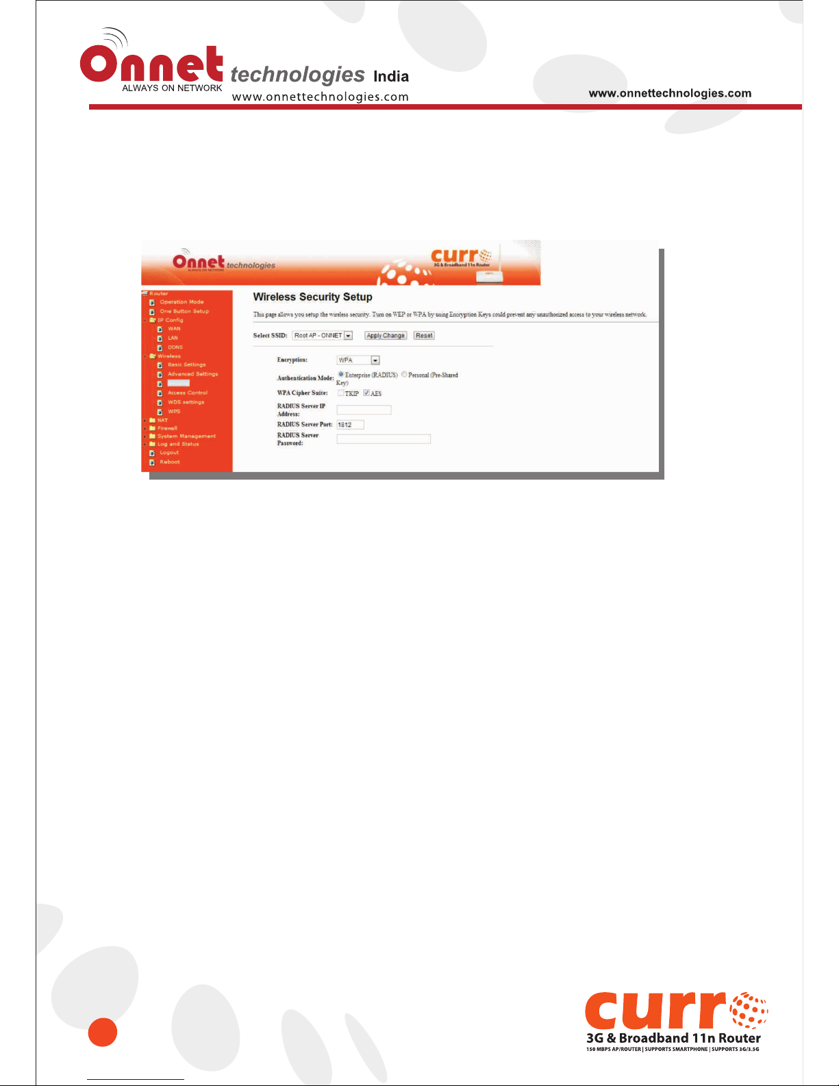
2. Encryption- WPA (WPA, WPA2, and WPA2 Mixed), WPA Authentication Mode
(1) Enterprise (RADIUS): Please fill in the RADIUS server Port, IP Address, and Password
(2) Personal (Pre-Shared Key): Pre-Shared Key type is ASCII Code; the length is between 8 to 63 characters. If
the key type is Hex, the key length is 64 characters.
(3) Apply Change & Reset: Click on 'Apply Changes' to save setting data. Or click 'Reset' to reset all the input
data.
Page 40
40
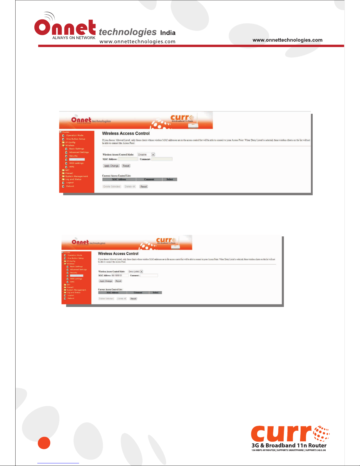
4.3 Wireless Access Control
Access Control allows user to block or allow wireless clients to access this router. Users can select the access
control mode, then add a new MAC address with a simple comment and click on “Apply Change” to save the
new addition. To delete a MAC address, select its corresponding checkbox under the Select column and click
on “Delete Selected” button.
Take the wireless card as the example.
(1) Please select Deny Listed in Wireless Access Control Mode first, and then fill in the MAC address what you
plan to block in the MAC Address field. Click Apply Changes to save the setting.
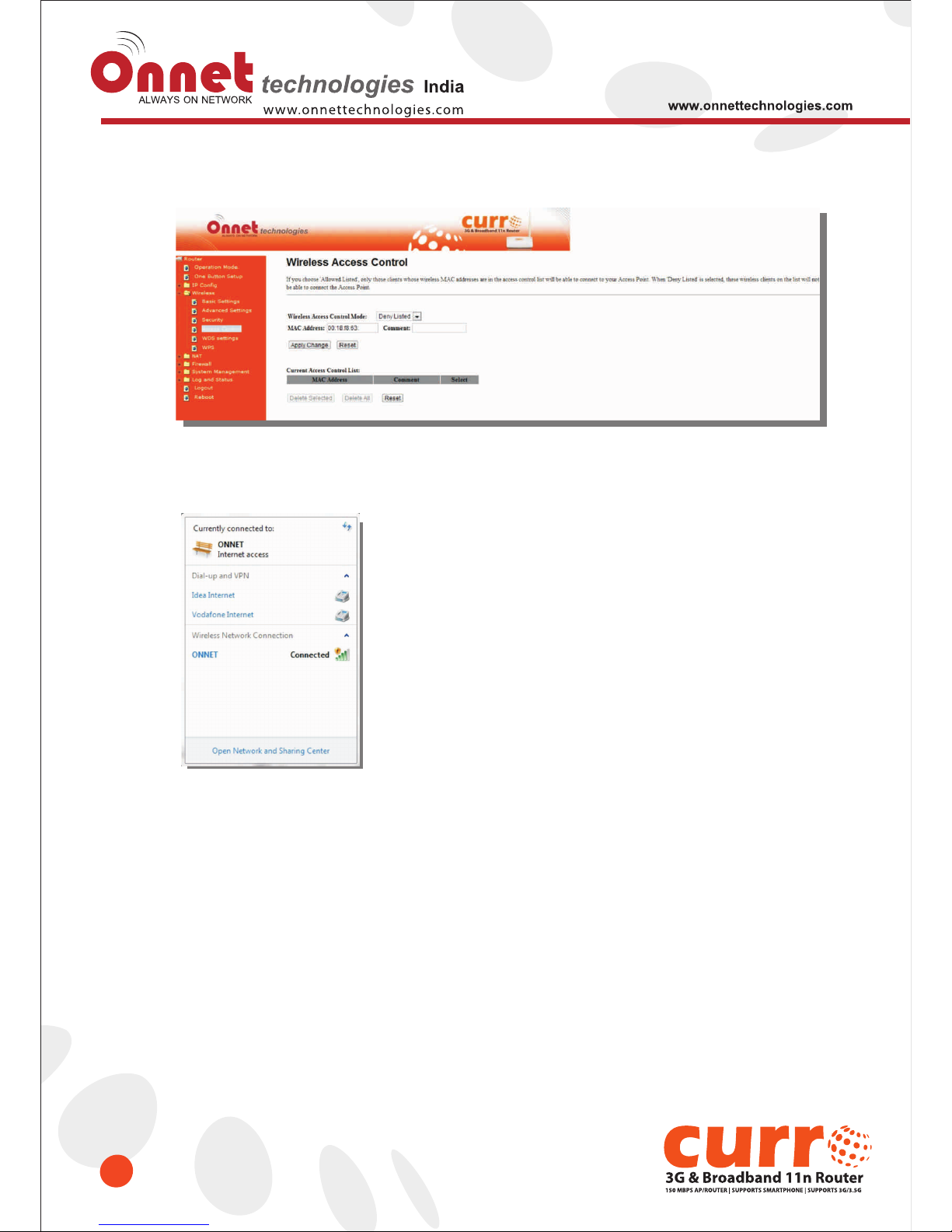
(2) The MAC address what you set will be displayed on the Current Access Control List.
Page 41
41
(2) The MAC address what you set will be displayed on the Current Access Control List.
(3) The wireless client will be denied by the wireless router.
Page 42
Chapter-5 Router Mode Security Setup
42
This section contains configurations for the Onet 3GUSB-4SWRouter's advanced functions such as: virtual
server, DMZ, and Firewall to provide your network under a security environment.
5.1 NAT
5.1.1 Virtual Server
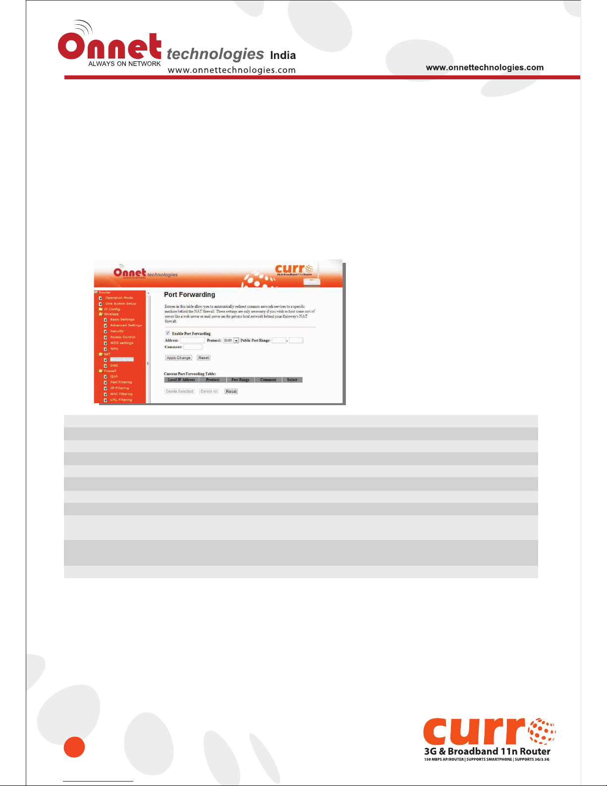
The Virtual Server feature allows users to create Virtual Servers by re-directing a particular range of service port
numbers (from the WAN port) to a particular LAN IP address.
Item
Enable Port Forwarding
Address
Protocol
Public Port Range
Private Port Range
Comment
Add
Current Port Forwarding
Table
Delete Selected & Delete All
Reset
Description
Select to enable Port Forwarding service or not.
Specify the IP address which receives the incoming packets.
Select the protocol type.
Enter the port number, for example 80-80.
Enter the port number, for example 20-22.
Add comments for this port forwarding rule.
Click on Add to enable the settings.
It will display all port forwarding regulation you made.
Click Delete Selected will delete the selected item.
Click Delete All will delete all items in this table.
Click Reset to cancel.
Page 43
43
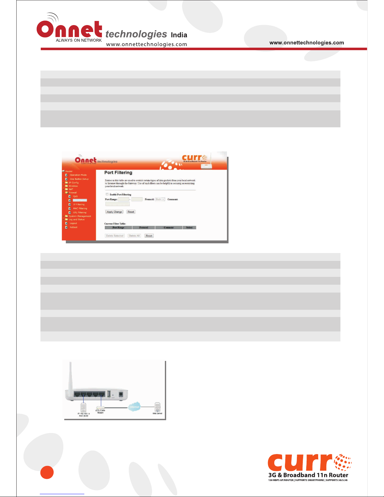
Please find the following figure to know that what the virtual server is configured as. The web server is located on
192.168.1.100, forwarding port is 80, and type is TCP+UDP.
5.1.2 Virtual DMZ
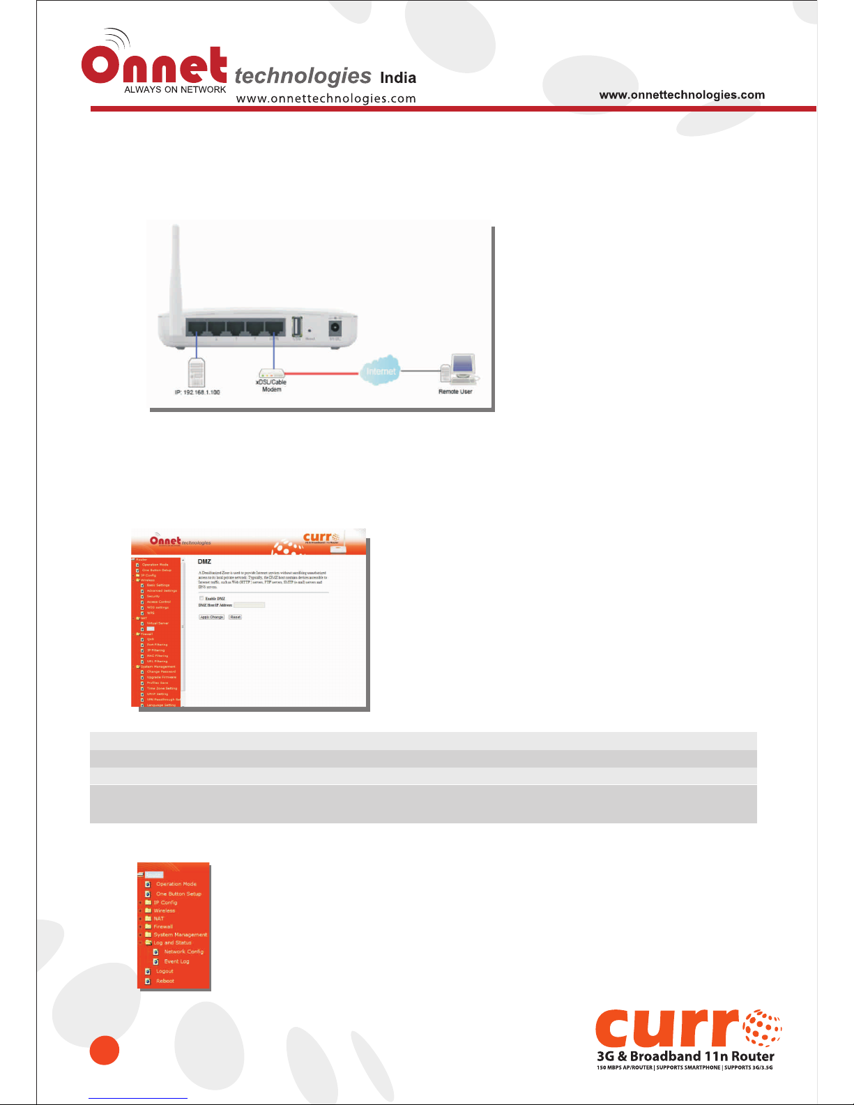
The DMZ feature allows one local user to be exposed to the Internet for special-purpose applications like Internet
gaming or videoconferencing. When enabled, this feature opens all ports to a single station and hence renders
that system exposed to intrusion from outside. The port forwarding feature is more secure because it only opens
the ports required by that application.
Item
Enable DMZ
DMZ Host IP Address
Apply Changes & Reset
Description
It will enable the DMZ service if you select it.
Please enter the specific IP address for DMZ host.
Click on Apply Changes to save the setting data. Or you may click on
Reset to clear all the input data.
5.1.2 Firewall
Page 44
44
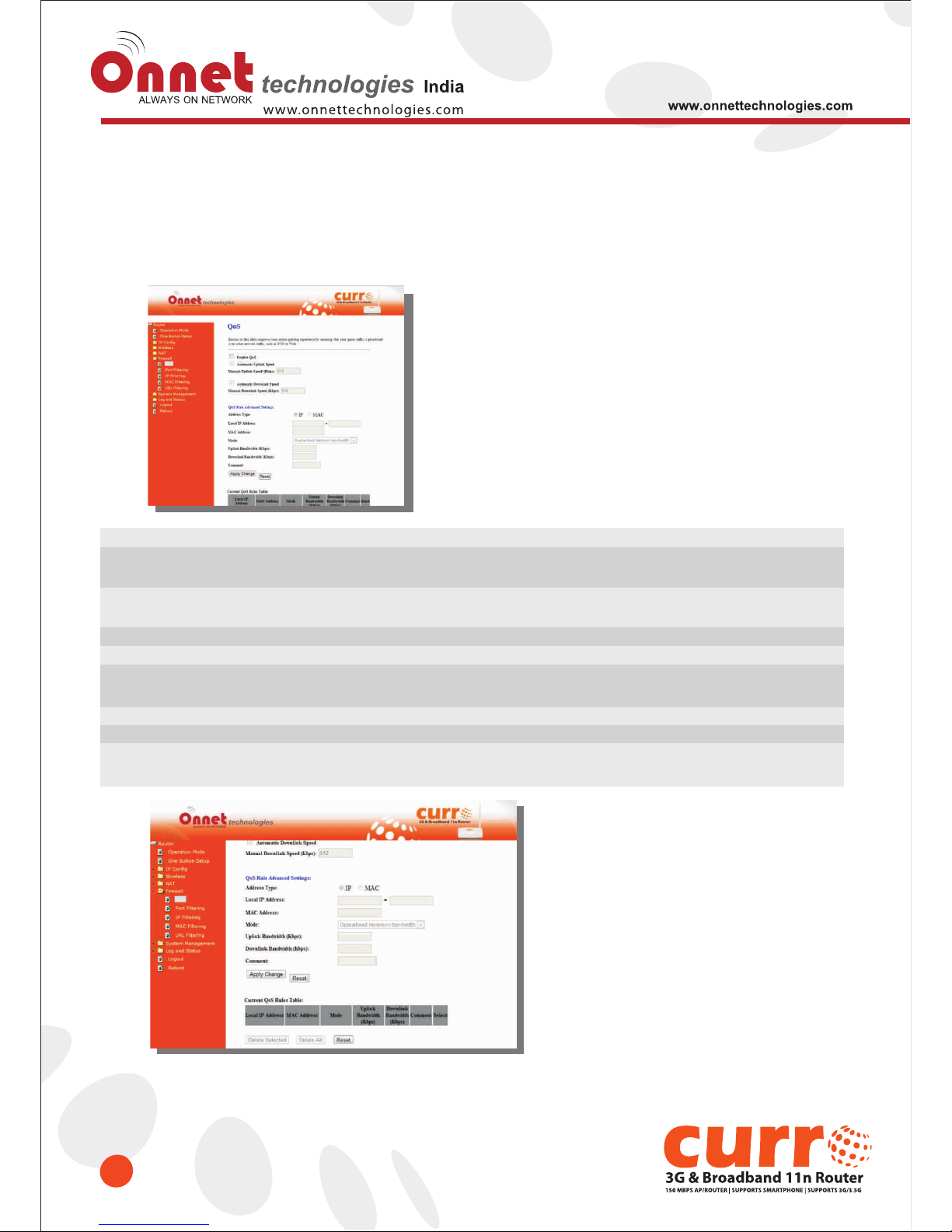
5.2.1 QoS
The QoS can let you classify Internet application traffic by source/destination IP address and port number.
To assign priority for each type of application and reserve bandwidth can let you have a better performance in
using critical real time services like Internet phone, video conference …etc.
Item
Enable QoS
Automatic uplink speed /
Manual Uplink Speed
QoS setting selection
QoS Rule Simple Setting:
Application selection
Priority
Comment
Apply Changes & Reset
Description
Check “Enable QoS” to enable QoS function for the WAN port. You also can
uncheck “Enable QoS” to disable QoS function for the WAN port.
Set the uplink speed by manual to assign the download or
upload bandwidth by the unit of Kbps or check the Automatic uplink speed.
Select Simple Settings or Advanced.
Select HTTP, FTP or Custom. You can set up port range and protocol type
by select Custom.
Highest, High, Normal or Low
Write your comment here.
Click on Apply Changes to save the setting data. Or you may click on
Reset to clear all the input data.
Page 45
45
QoS Rule Advance Setting:
Address Type
Mode
Bandwidth
Comment
Apply Changes & Reset
Set QoS by IP Address or MAC address
Select Guaranteed minimum bandwidth or Restricted maximum bandwidth
Key in the bandwidth.
Write your comment here.
Click on Apply Changes to save the setting data. Or you may click on
Reset to clear all the input data.
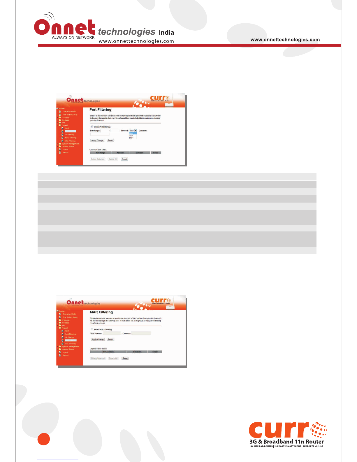
5.2.2 Port Filtering
When enabled packets are denied access to Internet/filtered based on their port address.
Item
Enable Port Filtering
Port Range
Protocol
Comment
Apply Changes & Reset
Current Filter Table
Delete Selected & Delete All
Reset
Description
Select Enable Port Filtering to filter ports.
Enter the port number that needs to be filtered.
Please select the protocol type of the port.
You can add comments for this regulation.
Click on Apply Changes to save the setting data.
Or you may click on Reset to clear all the input data.
It will display all ports that are filtering now.
Click Delete Selected will delete the selected item.
Click Delete All will delete all items in this table.
You can click Reset to cancel.
Port 80 has been blocked as the following illustrate.
Page 46
46
5.2.3 IP Filtering
When enabled, LAN clients are blocked / filtered from accessing the Internet based on their IP addresses.
Item
Enable IP Filtering
Local IP Address
Protocol
Comment
Apply Changes & Reset
Current Filter Table
Delete Selected & Delete All
Reset
Description
Please select Enable IP Filtering to filter IP addresses.
Please enter the IP address that needs to be filtered.
Please select the protocol type of the IP address
You can add comments for this regulation.
Click on Apply Changes to save the setting data.
Or you may click on Reset to clear all the input data.
It will display all ports that are filtering now.
Click Delete Selected will delete the selected item. Click Delete All will
delete all items in this table.
You can click Reset to cancel.
5.2.4 MAC Filtering
When enabled, filtering will be based on the MAC address of LAN computers. Any computer with its MAC address
on this list will be blocked from accessing the Internet.
Page 47
47
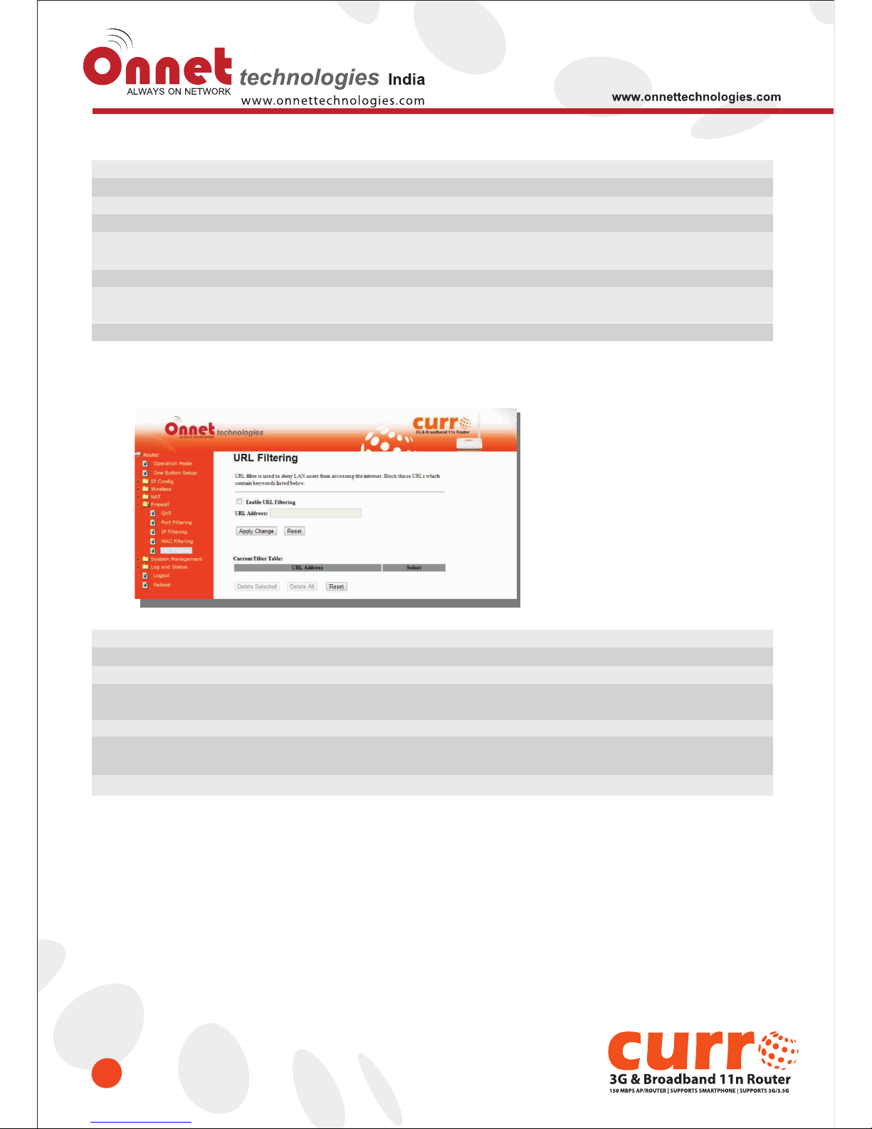
5.2.5 URL Filtering
URL Filtering is used to restrict users to access specific websites in internet
Item
Enable URL Filtering
URL Address
Apply Changes & Reset
Current Filter Table
Delete Selected & Delete All
Reset
Description
Please select Enable MAC Filtering to filter MAC addresses
Please enter the MAC address that needs to be filtered.
Click on Apply Changes to save the setting data. Or you may click on
Reset to clear all the input data.
It will display all ports that are filtering now.
Click Delete Selected will delete the selected item.
Click Delete All will delete all items in this table.
You can click Reset to cancel.
Item
Enable MAC Filtering
MAC Address
Comment
Apply Changes & Reset
Current Filter Table
Delete Selected & Delete All
Reset
Description
Please select Enable MAC Filtering to filter MAC addresses.
Please enter the MAC address that needs to be filtered.
You can add comments for this regulation.
Click on Apply Changes to save the setting data.
Or you may click on Reset to clear all the input data.
It will display all ports that are filtering now.
Click Delete Selected will delete the selected item.
Click Delete All will delete all items in this table.
You can click Reset to cancel.
Notes: This function will not be in effect when the Virtual Server is enabled. Please disable Virtual Server before activate
the URL Filtering function.
Page 48
Chapter-6 Advanced Setup
48
You can find advanced settings in this section.
Router Mode only.
AP Mode only.
WiFi AP Mode only.
AP
Router
WiFi-AP
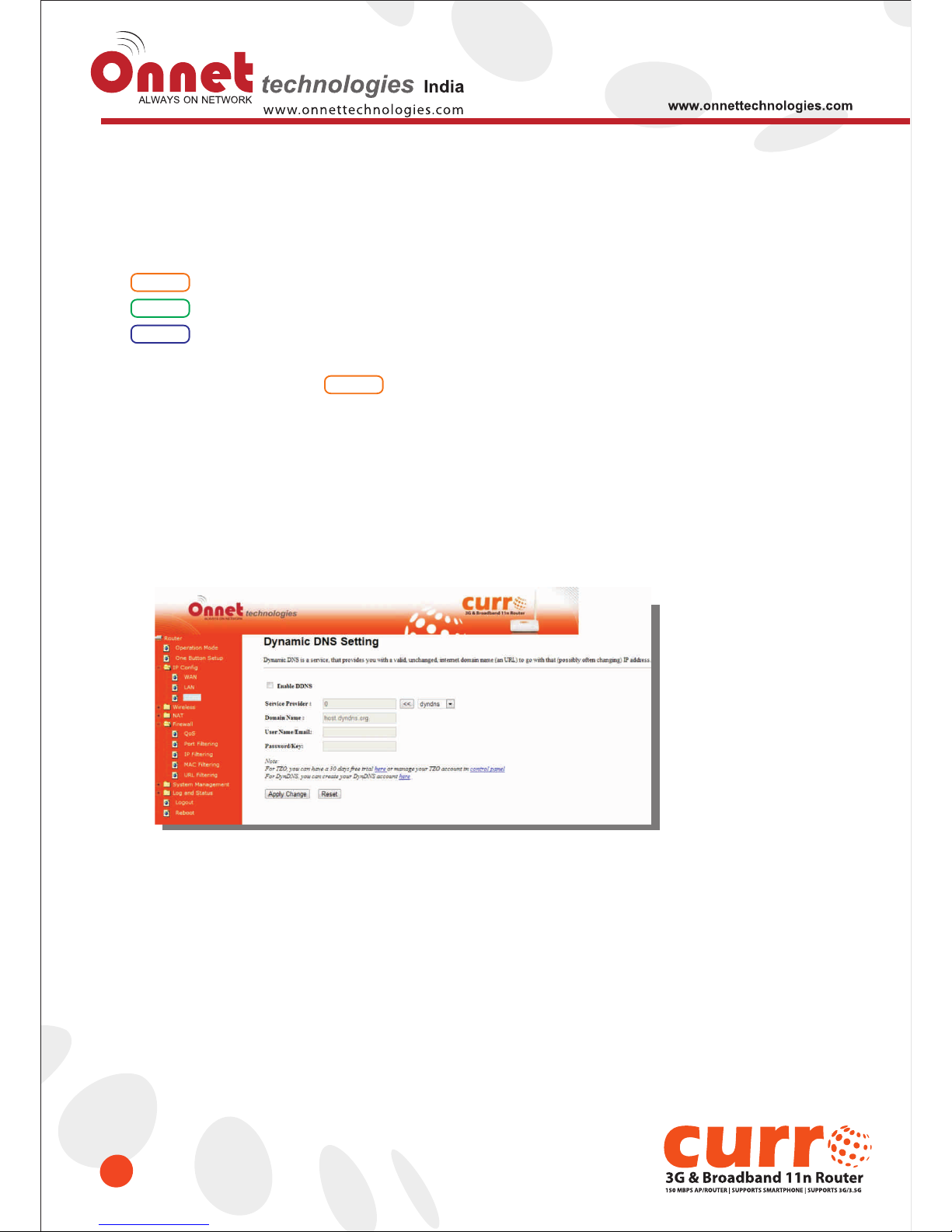
6.1 Dynamic DNS Setting
Router
You can assign a fixed host and domain name to a dynamic Internet IP address. Each time the
router boots up, it will re-register its domain-name-to-IP-address mapping with the DDNS service
provider. This is the way Internet users can access the router through a domain name instead of its
IP address.
Note: Make sure that you have registered with a DDNS service provider before enabling this
feature.
Page 49
49
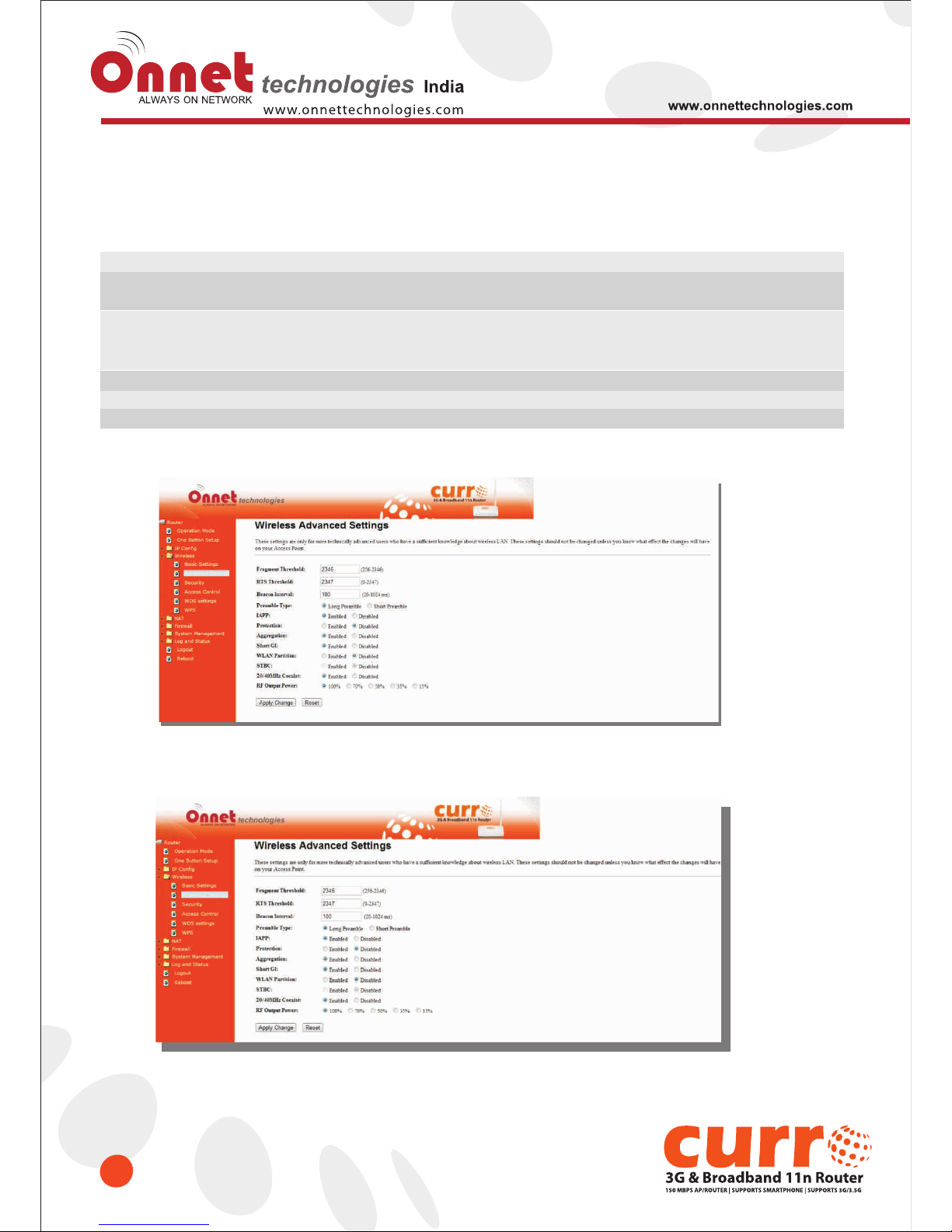
Please enter Domain Name, User Name/Email, and Password/Key. After entering, click on Apply Changes to
save the setting, or you may click on Reset to clear all the input data.
Item
Enable/Disable DDNS
Service Provider
User Name/Email
Password/Key
Apply & Cancel
Description
Select enable to use DDNS function. Each time your IP address to WAN is changed,
and the information will be updated to DDNS service provider automatically.
Choose correct Service Provider from drop-down list, here including DynDNS, TZO,
ChangeIP, Eurodns, OVH, NO-IP, ODS, Regfish embedded in
Onet 3GUSB-4SWRouter.
User name is used as an identity to login Dynamic-DNS service.
Password is applied to login Dynamic-DNS service.
Click on Apply button to continue. Click on Cancel button to clear the setting on this page.
6.2 Wireless Advanced Setup
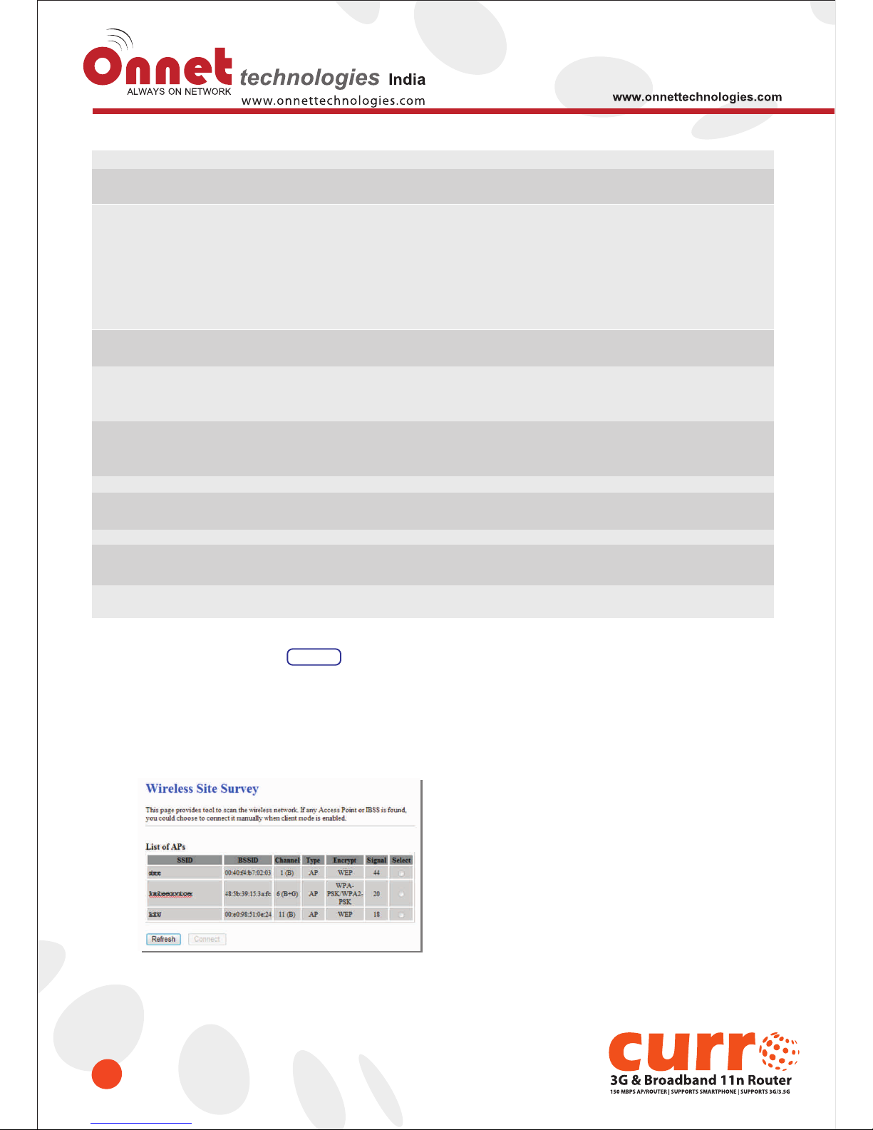
In Advanced Settings page, more 802.11 related parameters are configurable.
Page 50
50
6.2.1 Wireless Site Survey
This function provides users to search existing wireless APs or wireless base stations from ISP. You
can connect to a wireless AP manually in Wi-Fi AP mode. The designed AP will appear on SSID column
in Wireless Basic Setup page.
Please click on Refresh to refresh the list. Click Connect after select an existing AP to connect
Item
Fragment Threshold
RTS Threshold
Beacon Interval
Preamble Type
IAPP
Protection
Aggregation
Short GI
RF Output Power
Apply Changes & Reset
Description
To identify the maxima length of packet, the over length packet will be fragmentized.
The allowed range is 256-2346, and default length is 2346.
This value should remain at its default setting of 2347. The range is 0~2347.
Should you encounter inconsistent data flow, only minor modifications are recommended.
If a network packet is smaller than the present RTS threshold size, the RTS/CTS
mechanism will not be enabled. The router sends Request to Send (RTS) frames to a
particular receiving station and negotiates the sending of a data frame. After receiving an
RTS, the wireless station responds with a Clear to Send (CTS) frame to acknowledge
the right to begin transmission. Fill the range from 0 to 2347 into this blank.
Beacons are packets sent by an access point to synchronize a wireless network.
Specify a beacon interval value. The allowed setting range is 20-1024 ms..
PLCP is Physical layer convergence protocol and PPDU is PLCP protocol data unit
during transmission, the PSDU shall be appended to a PLCP preamble and header to
create the PPDU. It has 2 options: Long Preamble and Short Preamble.
Inter-Access Point Protocol is a recommendation that describes an optional extension to
IEEE 802.11 that provides wireless access-point communications among
multivendor systems.
Please select to enable wireless protection or not.
Enable this function will combine several packets to one and transmit it. It can reduce
the problem when mass packets are transmitting.
Users can get better wireless transmission efficiency when they enable this function.
Users can adjust RF output power to get the best wireless network environment.
Users can choose from 100%, 70%, 50%, 35%, and 15%.
Click on Apply Changes to save the setting data. Or you may click on
Reset to clear all the input data.
WiFi-AP
Page 51
51
6.2.2 WDS Settings
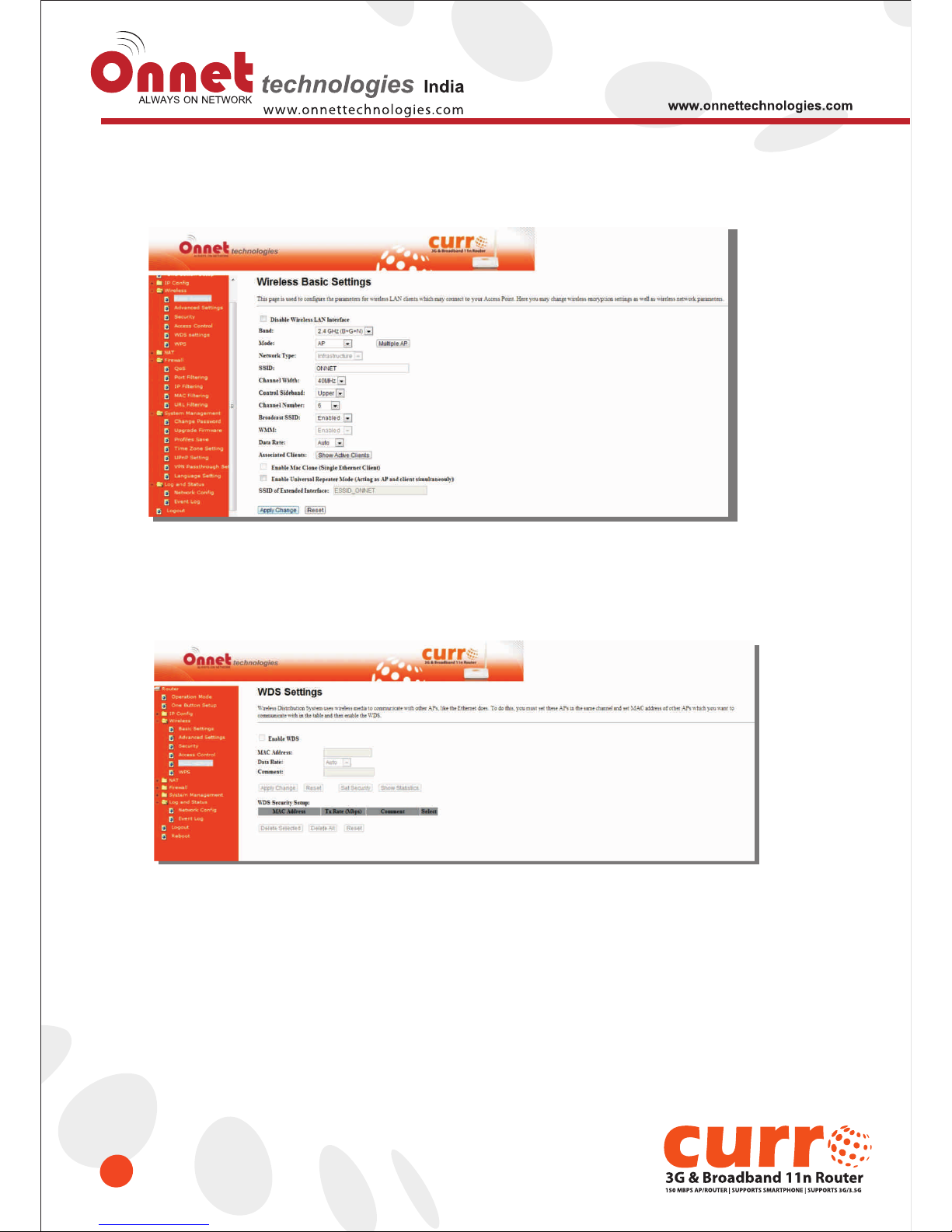
When selected in the Basic Settings page and enabled here, Wireless Distribution System (WDS)
enables the router to be used as a wireless bridge. Two Wireless-N Routers in bridge mode can
communicate with each other through their wireless interfaces. To accomplish this, all wireless routers
should be set to the same channel and the MAC address of other AP / Routers should be entered in the
table.
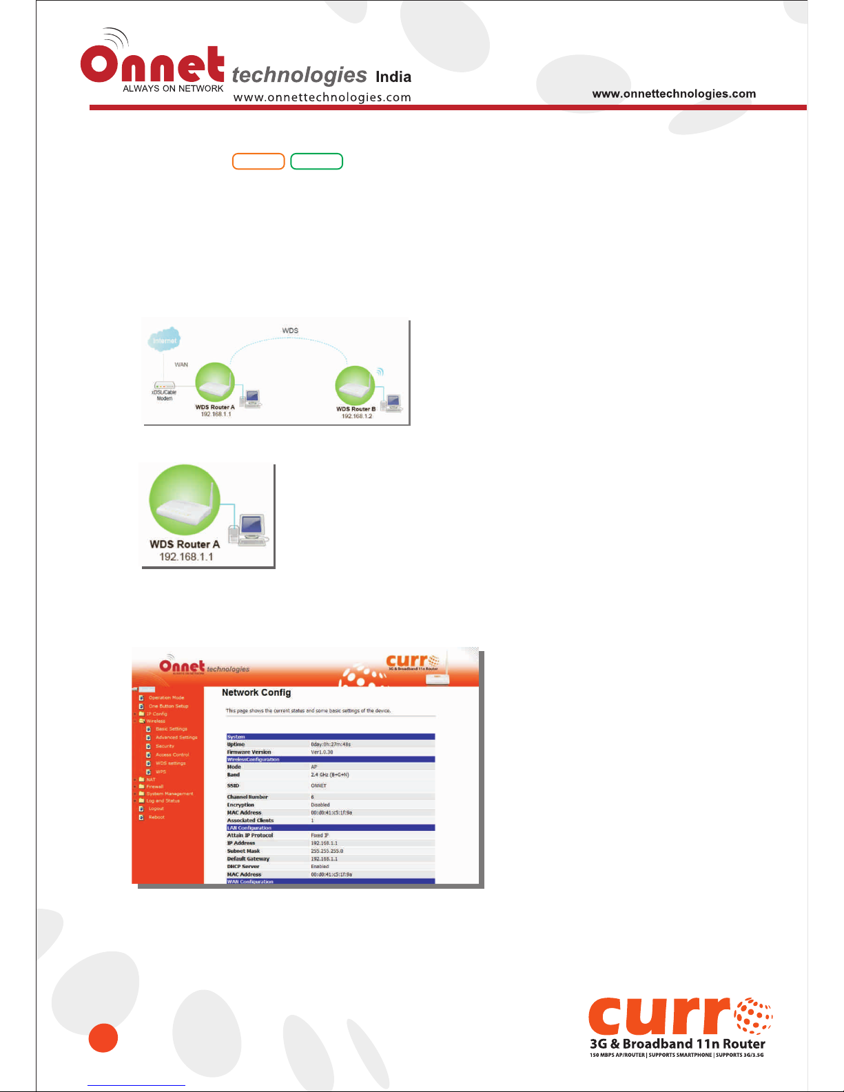
The WDS explanation is as the following picture.
Setup Router A
1. Please check the MAC address and Channel number from WDS Router A.
Router
AP
Page 52
52
2. Set the connection mode to “AP+WDS” from “Wireless Basic Setting”, and then select the channel
number (in this example is "6”). Click Apply Changes to save the setting.
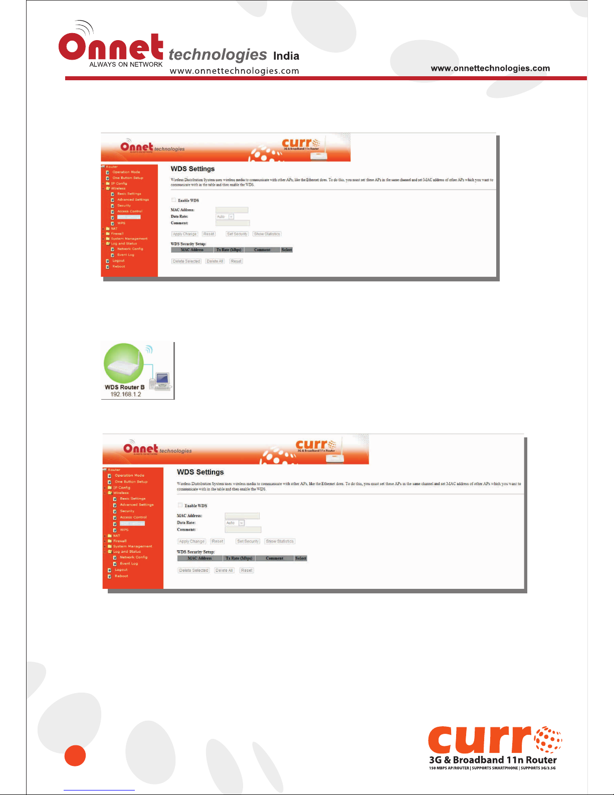
3. Enable WDS function from the page – “WDS Setting”, and then fill in the MAC address of Router B.
Click Apply Changes to save the setting data.
Page 53
53
4. The WDS AP List will show the WDS device MAC address after reboot.
5. Move on the setup to WDS Router B
Page 54
54
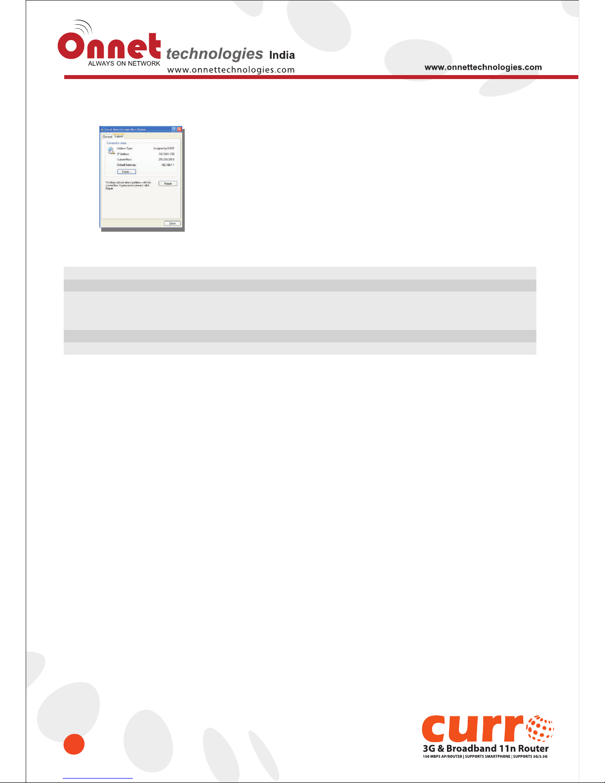
6. You will receive an IP address from Router A.
If you failed the WDS setting, please check you setting with refer to the list below.
Mode
LAN IP Address
Security
DHCP
MAC Address
Router A
Router
Set the same segment as the router B(Note 1)
Example :192.168.1.1
Set the same security as Router B
Enable
Same as Router B
Router B
AP
Set the same segment as the router A(Note 1)
Example :192.168.1.2
Set the same security as Router A
Disable
Same as Router A
Note 1: LAN IP address should be under the same segment but cannot be the same number.
Page 55
55
6.2.3 WPS
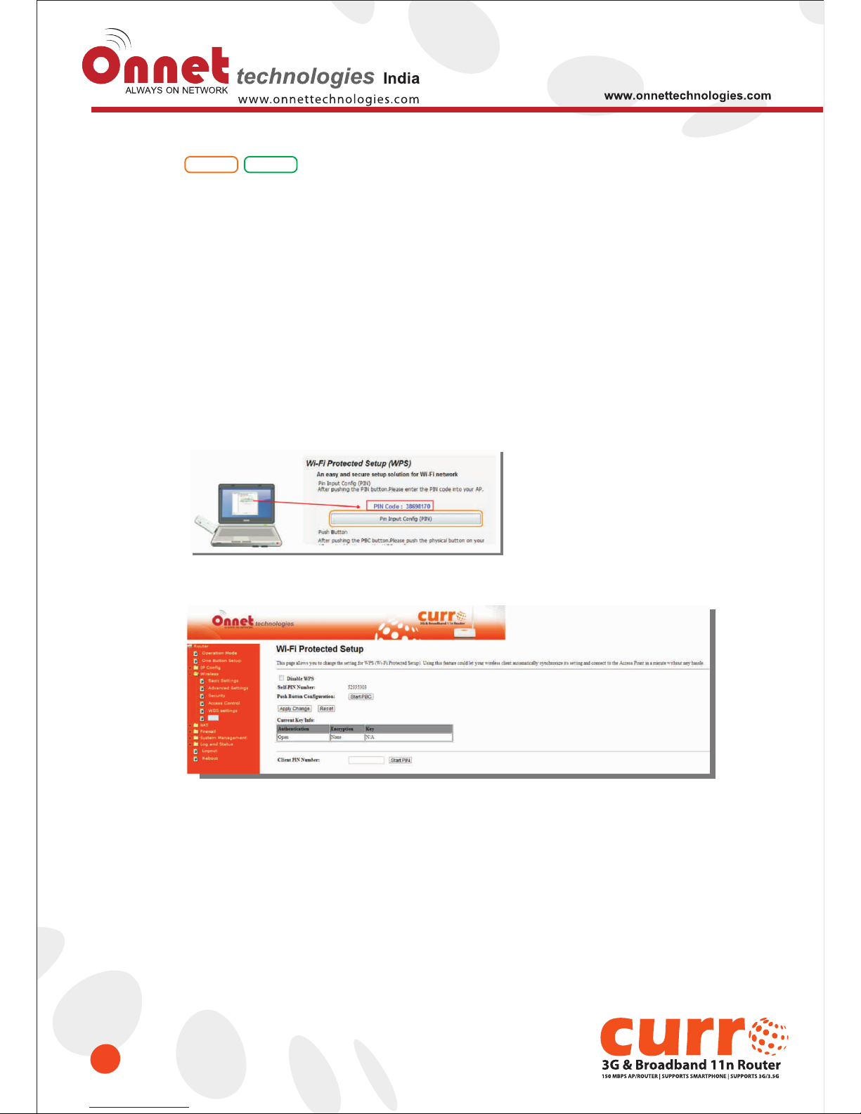
This page allows user to change the setting for WPS (Wi-Fi Protected Setup). Using this feature could let your
wireless client automatically synchronize it’s setting and connect to the Access Point in a minute without any
hassle. 3.5G Mimi Router could support both Self-PIN or PBC modes, or use the WPS button (at real panel) to
easy enable the WPS function.
PIN model, in which a PIN has to be taken either from a sticker label or from the web interface of the WPS device.
This PIN will then be entered in the AP or client WPS device to connect.
PBC model, in which the user simply has to push a button, either an actual or a virtual one, on both WPS devices
to connect.
Please follow instructions below to enable the WPS function.
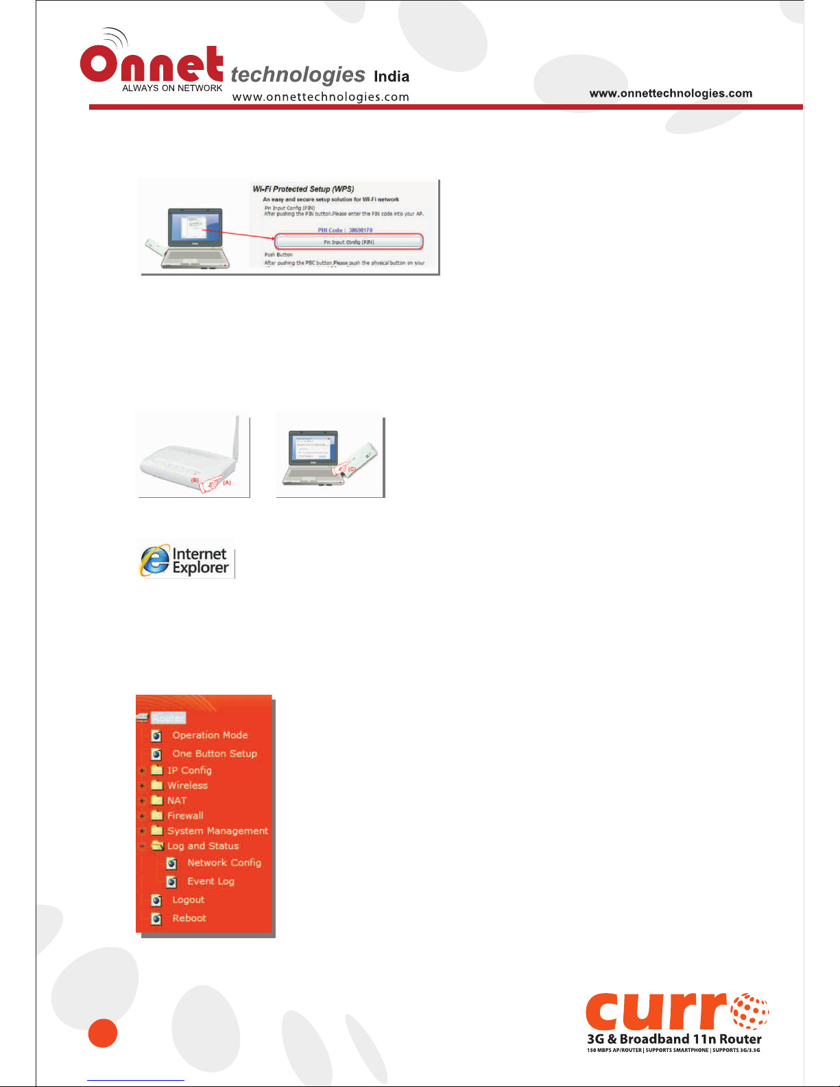
1. Setup Wireless LAN with WPS PIN :
(1) Get the WPS PIN number from wireless card and write it down.
(2). Fill in the PIN number from the wireless card in Client PIN Number field, and then click
“Start PIN”.
Router
AP
Page 56
56
(3). Click PIN from Adapter Utility to complete the WPS process with the wireless router.
2. Start PBC:
(1). Press the WPS button
(A) from Onet 3GUSB-4SWRouter and wait for Wireless/WPS LED light
(B) changed into orange.
(2). Press the WPS button
(C) from the adapter until the setup window shows up.
(3). Open a web browser to check the internet connection.
Please also refer to section 4.1.1 WPS setup for more details.
6.3 System Management
This section including Change Password, Firmware Upgrade, Profiles Save, Time Zone Setting, UPnP Setting,
VPN Pass-through setting and Language Setting. It is easy and helpful for users for more detailed settings.
Page 57
57
6.3.1 Change Password
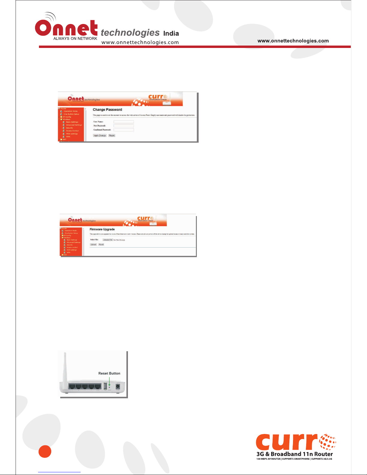
Users can set or change user name and password used for accessing the web management interface in this
section.
Click on Apply Changes to save the setting data. Or you may click on Reset to clear all the input data.
6.3.2 Firmware Upgrade
This function can upgrade the firmware of the router. There is some risk while doing firmware upgrading.
Firmware upgrade is not recommended unless a significant fault is found and published on official website. If you
feel the router displays unusual behaviors and is not caused by the ISP and environment you can check the
website (http://www.onnettechnologies.com) for any later version of firmware. Download the firmware to your
computer, click Browser and point to the new firmware file. Click Upload to upgrade the firmware. Please let the
machine reboot completely.
Reset button:
On the front panel of this router, a reset button is provided. If you cannot login the administrator page or have
forgotten your password; or the router has problems that you can’t solve ,push the reset button for 5 seconds with
a pin. The router will reboot and all settings will be restored to factory default settings. If the problem still exists,
you can visit our web site to check for any firmware updates and for downloads to solve the problem.
Caution: To prevent that firmware upgrading is interrupted by other wireless signals and causes failure. We
recommend users to use wired connection during upgrading.
Note: The firmware upgrade will not remove your previous settings.
Page 58
58
6.3.3 Profile Save
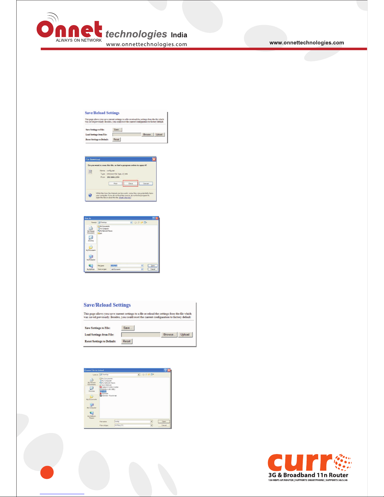
Users can create a backup file that contains current router settings. This backup file can be used to restore router
settings. This is especially useful in the event you need to reset the router to its default settings.
1. Save Configuration
(1). Click Save
(2). Please click “Save” to save the configuration to your computer.
(3). Select the location which you want to save file, then click Save.
2. Load configuration file
(1). Click Browser
(2). Select configuration file then click Open
Page 59
59
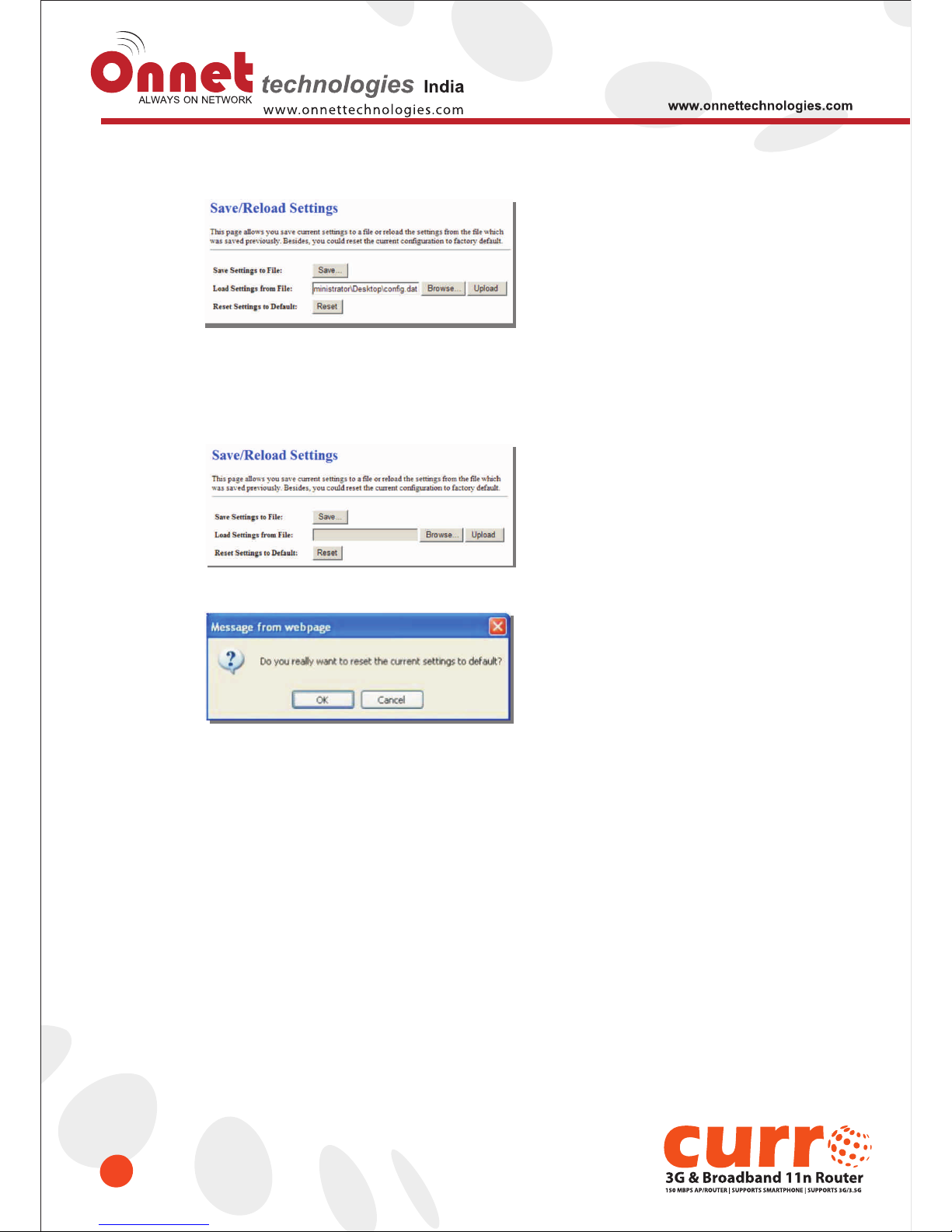
(3). Click Upload to upload configuration file to Onet 3GUSB-4SWRouter.
(4). After 90 seconds, Onet 3GUSB-4SWRouter will reboot automatically.
3. Reload factory default setting
(1). Please click Reset
(2). Please click OK to start reload factory default setting to Onet 3GUSB-4SWRouter.
(3). After 90 seconds, Onet 3GUSB-4SWRouter will reboot automatically.
Page 60
60
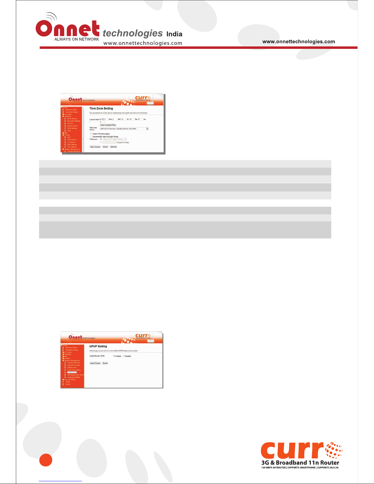
6.3.4 Time Zone Setting
Users can synchronize the local clock on the router to an available NTP server (optional). To complete this
setting, enable NTP client update and select the correct Time Zone.
Item
Current Time
Time Zone Select
Enable NTP client update
Automatically Adjust
Daylight Saving
NTP Server
Apply Changes & Reset &
Refresh
Description
Users can input the time manually.
Please select the time zone.
Please select to enable NTP client update or not.
Please select to enable Automatically Adjust Daylight Saving or not.
Please select the NTP server from the pull-down list, or you can enter the
NTP server IP address manually.
Please click on Apply Changes to save the setting data.
Or you may click on Reset to clear all the input data. Or you may click on
Refresh to update the system time on the screen.
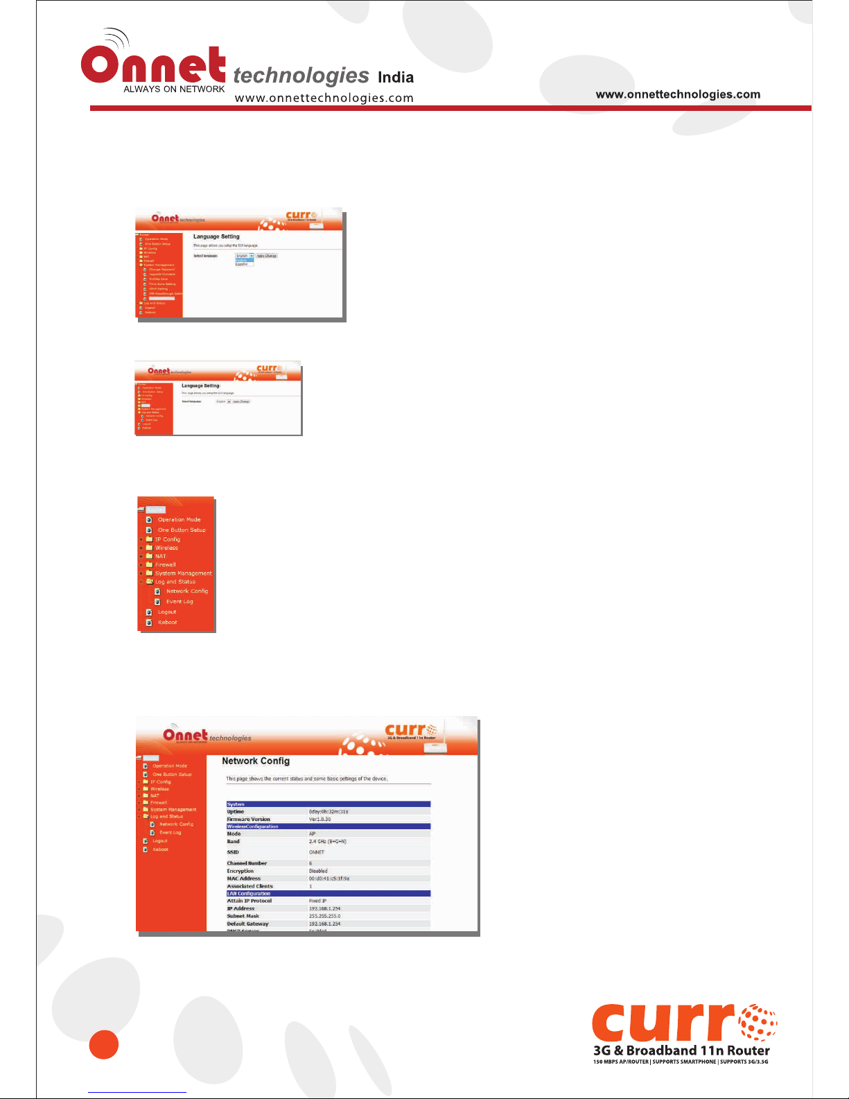
6.3.5 UPnP Setting
Universal Plug and Play (UPnP) is a standard of networking protocols promulgated by the UPnP Forum. The
goals of UPnP are to allow devices to connect seamlessly and to simplify the implementation of networks in the
home (data sharing, communications, and entertainment) and in corporate environments for simplified
installation of computer components. Onet 3GUSB-4SWRouter supports UPnP function, and can cooperate
with other UPnP devices. When you activate UPnP, please click My Network Places. Users will see an Internet
Gateway Device icon. By click the icon, users can enter the GUI of the router. If you do not wish to use UPnP, you
can disable it.
Enable/Disable UPnP: Select to enable or disable this function.
Page 61
61
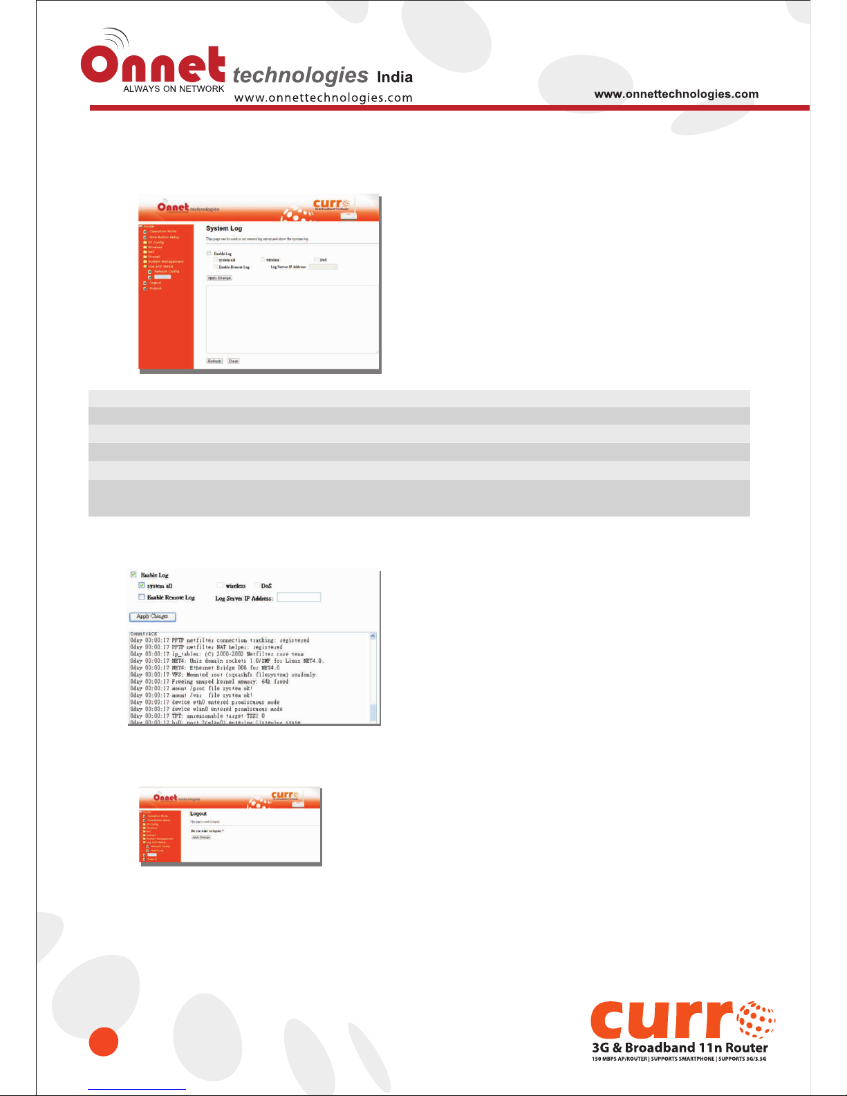
6.3.6 Language Setting
The Onet 3GUSB-4SWRouter provide 12 language for Web GUI. You can select the LANGUAGE interface from
the dropdown list and by following steps.
When you see the screen message change to the selected language, the setup is completed.
6.4 Log & Status
The category provides Network Config and Event Log status for users to know the operation status
6.4.1 Network Config
Users can check the Internet status under this category, including Firmware version, Wireless setting,
Connecting Time, WAN, TCP/IP …information.
Page 62
62
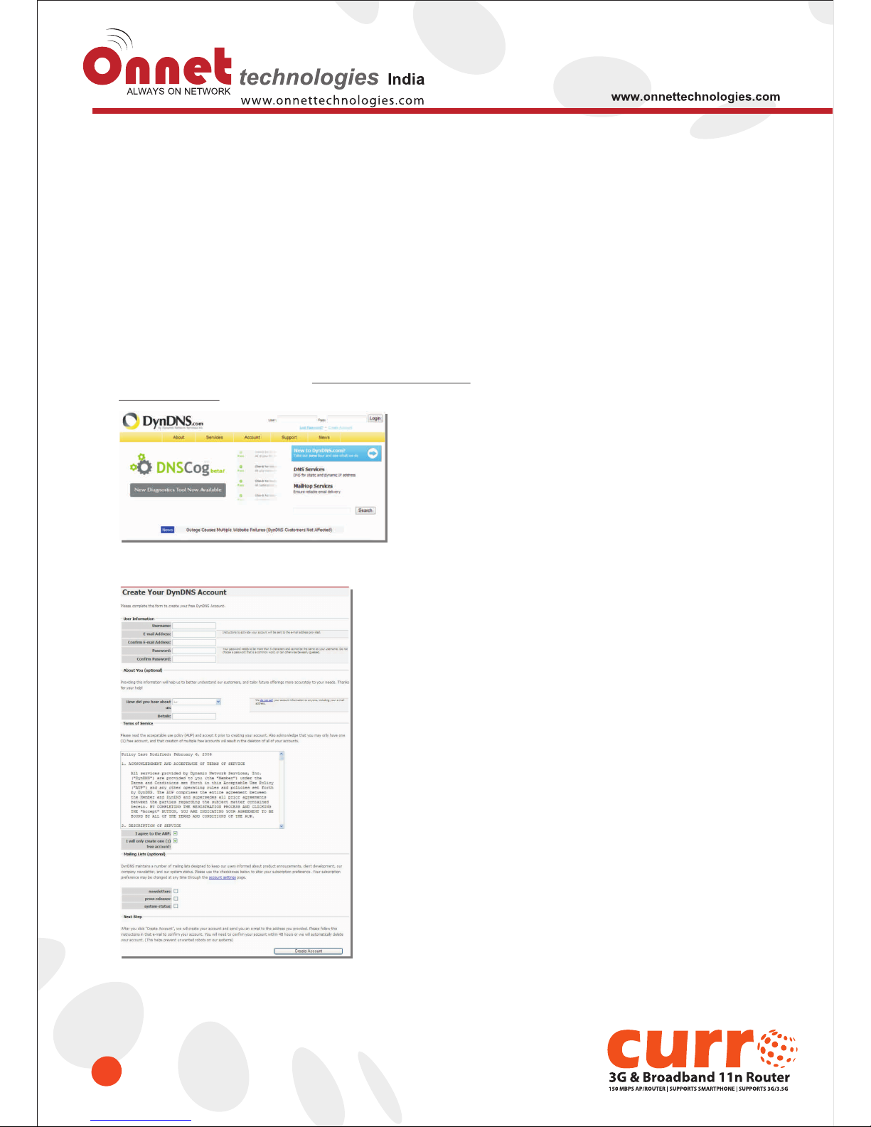
6.4.2 Event Log
You may enable the event log feature here.
* The following figure is an example when users click Apply Changes to record the event log.
6.5 Logout
This function logs out the user.
Item
Enable Log
System all, Wireless, & DoS
Enable Remote Log
Log Server IP Address
Apply Changes & Refresh &
Clear
Description
You may choose to enable Event Log or not.
Please select the event you want to record.
You may choose to enable the remote event log or not.
Please input the log server IP Address.
Click on Apply Changes to save the setting data. Click on Refresh to renew the
system time, or on Clear to clear all the record.
Page 63
Chapter-7 DDNS Service Application
63
DDNS is a service that changes the dynamic IP to a static IP. Setting a DDNS can solve the problem of multiple IP
addresses alloted by different ISP every time. After setting the Router, your host name would correspond to your dynamic
IP. Moreover, via the host name application, it could be easier for you to use FTP, Webcam and Printer remotely.
Dynamic DNS allows you to create an assumed name as a dynamic IP address to a static host name. Please configure
the dynamic DNS below. Please select Dynamic DNS under the IP Config folder, and follow the instructions below to
enter the Dynamic DNS page to configure the settings you want.
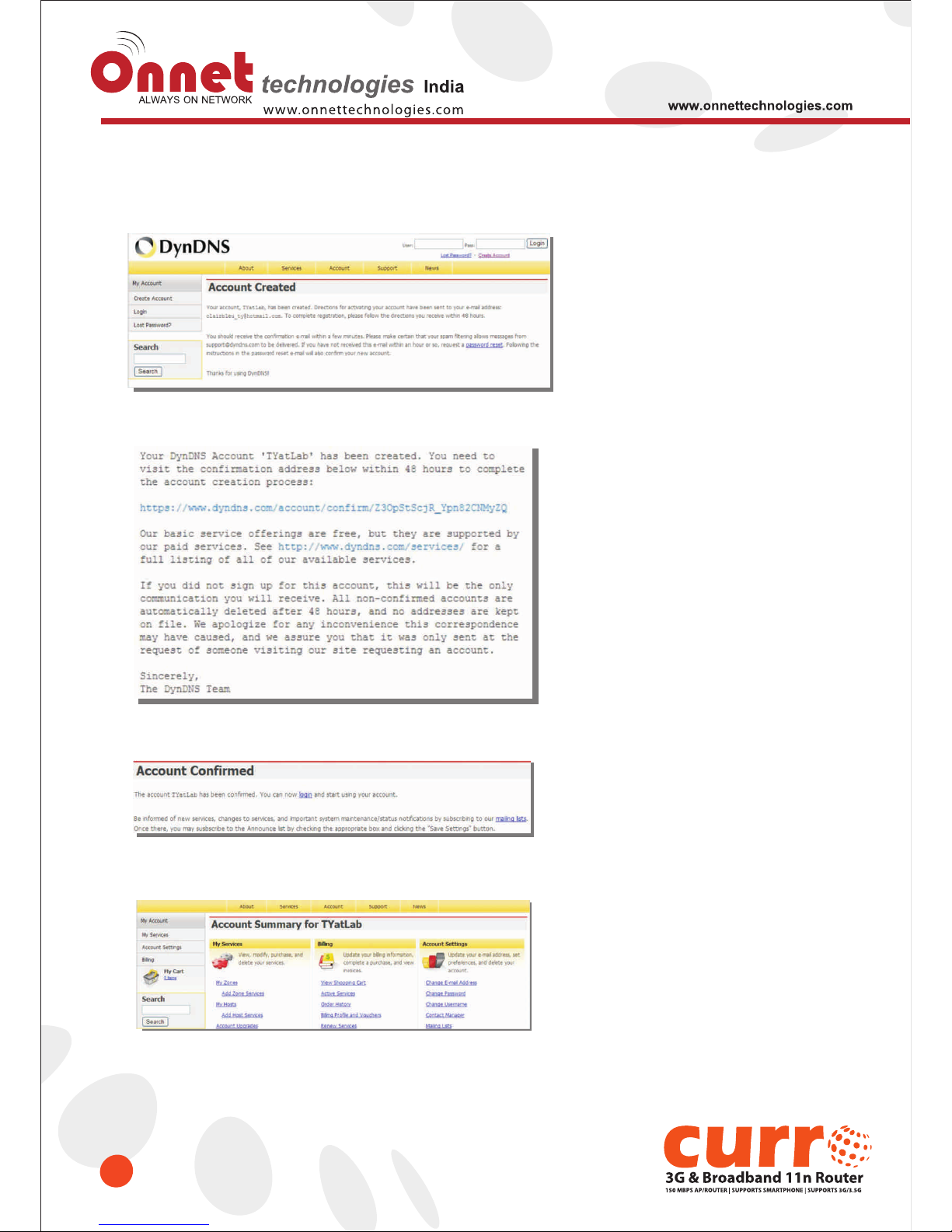
If you don’t have a DDNS account, please follow the steps to complete your DDNS with Dynamic IP settings.
1. First access the Internet and fill http://www.dyndns.com/ into the address field of your web browser, then click
Create Account.
2. Fill in the form as required, and then click on Create Account button.
Page 64
64
3. After you have this “account created message”, check your mailbox. You will receive a mail from DynDNS website.
4. Click on the indicated address within your mail to confirm.
5. Click on login.
6. Click My Services after logging in.
Page 65
65
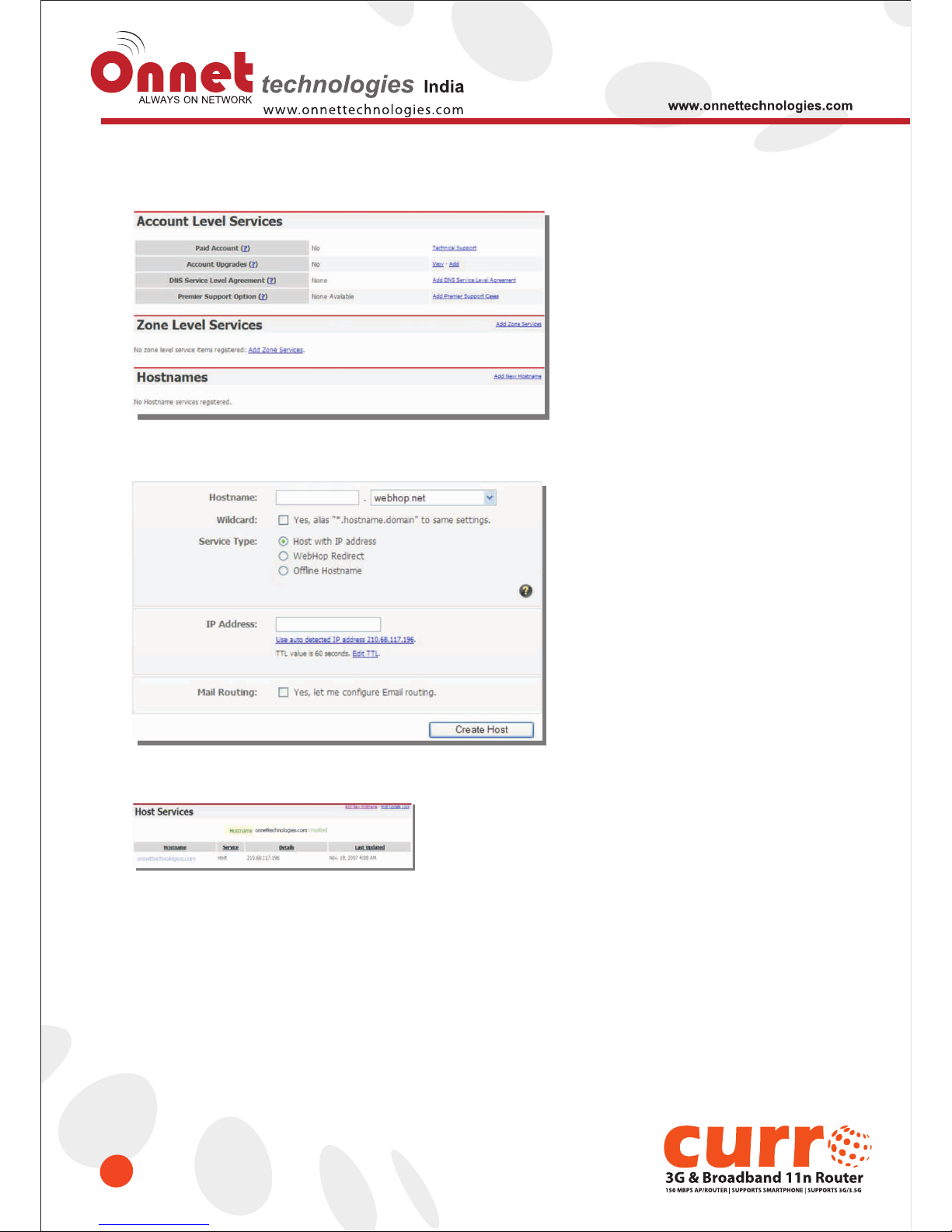
7. Click Add New Hostname.
8. Put in your favorite hostname and service type, and then click Create Host after finished.
9. Your hostname has been created when you see the following page.
Page 66

66
Chapter-8 Q & A
8.1 Installation
1. Q: Where is the XDSL Router installed on the network?
A: In a typical environment, the Router is installed between the XDSL line and the LAN. Plug the XDSL Router into
the XDSL line on the wall and Ethernet port on the Hub (switch or computer).
2. Q: Why does the throughput seem slow?
A: To achieve maximum throughput, verify that your cable doesn’t exceed 100 meter. If you have to do so, we advise
you to purchase a bridge to place it in the middle of the route in order to keep the quality of transmitting signal. Out
of this condition you would better test something else.
• Verify network traffic does not exceed 37% of bandwidth.
• Check to see that the network does not exceed 10 broadcast messages per second.
• Verify network topology and configuration.
8.2 LED
1. Why doesn’t Onet 3GUSB-4SWRouter power up?
A: Check if the output voltage is suitable, or check if the power supply is out of order.
2. The Internet browser still cannot find or connect to Onet 3GUSB-4SWRouter after verifying the IP address
and LAN cable, the changes cannot be made, or password is lost.
A: In case Onet 3GUSB-4SWRouter is inaccessible; you can try to restore its factory default settings. Please press
the “Reset” button and keep it pressed for over 7 seconds and the light of STATUS will vanish. The LEDs will flash
again when reset is successful.
3. Why does Onet 3GUSB-4SWRouter shut down unexpectedly?
A: Re-plug your power adapter. Then, check the STATUS indicator; if it is off, the internal flash memory is damaged.
For more help, please contact with your provider.
8.3 IP Address
1. Q: What is the default IP address of the router for LAN port?
A: The default IP address is 192.168.1.1 with subnet mask 255.255.255.0
2. Q: I don't know my WAN IP.
A: There are two ways to know.
Way 1: Check with your Internet Service Provider.
Way 2: Check the setting screen of Onet 3GUSB-4SWRouter. Click on Status & Log item to select Network
Configuration on the Main Menu. WAN IP is shown on the WAN interface.
3. How can I check whether I have static WAN IP Address?
A: Consult your ISP to confirm the information, or check Network Configuration in Onet 3GUSB-4SWRouter ’s Main
Menu.
4. Will the Router allow me to use my own public IPs and Domain, or do I have to use the IPs provided by the
Router?
A: Yes, the Router mode allows for customization of your public IPs and Domain.
Page 67

67
8.4 OS Setting
1. Why can't my computer work online after connecting to Onet 3GUSB-4SWRouter?
A: It's possible that your Internet protocol (TCP/IP) was set to use the following IP address. Please do as the
following steps. (Windows 2000 & XP) Start> Settings> Network and Dial-up Connections> double click on
Internet Protocol(TCP/IP)> select obtain IP address automatically> Click on OK button. Then, open Internet
browser for testing. If you still can't go online, please test something else below.
• Verify network configuration by ensuring that there are no duplicate IP addresses.
• Power down the device in question and ping the assigned IP address of the device. Ensure no other device
responds to that address.
• Check that the cables and connectors or use another LAN cable.
2. Q: Why can't I connect to the router's configuration utility?
A: Possible Solution 1: Make sure that your Ethernet connect properly and securely. Make sure that you've plugged
in the power cord.
Possible Solution 2: Make sure that your PC is using an IP address within the range of 192.168.1.2 to
192.168.1.254. Make sure that the address of the subnet mask is 255.255.255.0. If necessary, the Default Gateway
data should be at 192.168.1.1. To verify these settings, perform the following steps:
Windows 2000, or XP Users:
1. Click on Windows Start > click on Run > input cmd > click on OK button.
2. At the DOS prompt, type ipconfig/all.
3. Check the IP Address, Subnet Mask, Default Gateway data. Is this data correct? If the data isn't correct. Please
input ipconfig/release > press Enter > input ipconfig/renew > press Enter.
Possible Solution 3: Verify the connection setting of your Web browser and verify that the HTTP Proxy feature of
your Web browser is disabled. Make these verifications so that your Web browser can read configuration pages
inside your router. Launch your Web browser.
Internet Explorer Users:
1. Click on Tools > Internet Options > Connections tab.
2. Select never dial a connection, click on Apply button, and then click on OK button.
3. Click on Tools and then click on Internet Options.
4. Click on Connections and then click on LAN Settings.
5. Make sure none of the check boxes are selected and click on OK button.
6. Click on OK button.
Netscape Navigator Users:
1. Click on Edit > Preferences > double-click Advanced in the Category window.
2. Click on Proxies > select Direct connection to the Internet > click on OK button.
3. Click on Edit again and then click on Preferences.
4. Under category, double-click on Advanced and then click on Proxies.
5. Select Direct connection to the Internet and click on OK button.
6. Click on OK button.
Page 68

68
3. Q: Web page hangs, corrupt downloads, or nothing but junk characters is being displayed on the screen.
What do I need to do?
A: Force your NIC to 10Mbps or half duplex mode, and turn off the "Auto-negotiate" feature of your NIC as a
temporary measure. (Please look at the Network Control Panel, in your Ethernet Adapter's Advanced Properties
tab.)
4. Q: Why can't I connect to the Web Configuration?
A: you can remove the proxy server settings in your web browser.
8.5 Onet 3GUSB-4SWRouter Setup
1. Q: Why does Onet 3GUSB-4SWRouter’s setup page shut down unexpectedly?
A: If one of the pages appears incompletely in Onet 3GUSB-4SWRouter ’s setup pages, please click on Logout item
on the Main Menu before shutting it down. Don’t keep it working. Then, close Internet browser and open it again for
going back to the previous page.
2. Q: Why can’t my USB devices and LAN ports work properly after setting the DHCP?
A: There are two rules over here.
Rule1: After connecting USB devices, please reboot your Router.
Rule2: Before finishing the DHCP setup, please don’t connect any computer to LAN ports, because the conflict of
having the same IP may occur and cause some computers a lot of trouble.
Notice: Make sure that you always click on the Apply button after configuring each setting. And in order to
let other LAN ports work properly, please reboot your PC.
3. Q: I don’t know how to configure DHCP.
A: DHCP is commonly used in the large local network. It allows you to manage and distribute IP addresses from 2 to
254 throughout your local network via Onet 3GUSB-4SWRouter . Without DHCP, you would have to configure each
computer separately. It’s very troublesome. Please Open Internet browser > Input 192.168.1.1 in the website
blank field > Select DHCP Server under the IP Config Menu. For more information, please refer to 3.3.2 (Router
Mode) or 4.3.1 (AP Mode).
4. Q: How do I upgrade the firmware of Onet 3GUSB-4SWRouter ?
A: Periodically, a new Flash Code is available for Onet 3GUSB-4SWRouter on your product supplier’s website.
Ideally, you should update Onet 3GUSB-4SWRouter ’s Flash Code using Firmware Upgrade on the System
Management menu of Onet 3GUSB-4SWRouter Settings
5. Q: My 11n Mobile Server Router cannot connect to the ISP?
A: There are three possible solutions.
1. Check the Cable/XDSL modem is power on.
2. Check the Cable/XDSL link light is on to verify a good physical connection.
3. Check the WAN port LED to verify if the Cable/XDSL modem is connected to the router:
If your ISP Login method is following, please make sure the username and password are correct or not.
If your ISP is using dynamic IP addressing (DHCP) then the DHCP protocol does not have the authentication
feature. Some Cable service providers often use the following to determine user’s identification.
Page 69

69
6. Q: Why is that I can ping to outside hosts, but cannot access Internet websites?
A: Check the DNS server settings on your PC. You should get the DNS servers settings from your ISP. If your PC is
running a DHCP client, remove any DNS IP address setting. As the router assign the DNS settings to the DHCPclient-enabled PC.
7. Q: Onet 3GUSB-4SWRouter couldn’t save the setting after click on Apply button?
A: Onet 3GUSB-4SWRouter will start to run after the setting finished applying, but the setting isn’t written into
memory. We recommend that if you want to make sure the setting would be written into memory, please reboot the
device via Reboot under System Management directory.
8.6 Wireless LAN
1. Q: Why couldn’t my wireless notebook work on-line after checking?
A: Generally, Wireless networks may sometimes be complicated to set up, particularly if you're dealing with
encryption and products from different vendors. Any number of variables can keep your workstations from talking to
each other. Let's go over some of more common ones.
For starters, verify that your router and your workstation are using the same SSID descriptions. SSID acts as a
password when a mobile device tries to connect to the wireless network. The SSID also differentiates one WLAN
from another, so all access points and all devices attempting to connect to a specific WLAN must use the same
SSID. A workstation will not be permitted to connect to the network unless it can provide this unique identifier. This is
similar to the function of your network's Workgroup or Domain name.
When you're experiencing conductivity problems, it is always best to keep things simple. So next you are going to do
is that, please disable any WEP encryption you might have configured.
Successful implementation of encryption also includes the use of a shared key. A HEX key is the most common, but
other formats are also used. This key identifies the workstation to the router as a trusted member of this network.
Different manufacturers can implement this key technology in ways that might prevent them from working correctly
with another vendor's products. So pay attention to detail is going to be the key to a successful installation.
Next make sure the router and the NIC are configured to use the same communications channel. There are
normally 11 of them, and the default channel can also vary from vendor to vendor. You might also want to confirm
that the router has DHCP services enabled and an address pool configured. If not, the NIC won't be able to pick up
an IP address. I have run across a few access points that offer DHCP services but do not assign all of the needed IP
information to the NIC. As a result, I was able to connect to the network, but could not browse the web. The point is,
don't assume anything. Verify for yourself that all of the required settings are being received by the workstation.
Finally, you might want to keep the system you're trying to configure in the same room as the router, at least during
the initial configuration, in order to minimize potential interference from concrete walls or steel beams.
Page 70

70
2. Q: My PC can’t locate the Wireless Access Point.
A: Check the following:
• Your PC is set to Infrastructure Mode. (Access Points are always in Infrastructure Mode.)
• The SSID on your PC and the Wireless Access Point are the same. Remember that the SSID is case-sensitive.
So, for example “Workgroup” does NOT match “workgroup”.
• Both your PC and the Wireless Access Point must have the same setting for WEP. The default setting for the
Wireless Router is disabled, so your wireless station should also have WEP disabled.
• If WEP is enabled on the Wireless Router, your PC must have WEP enabled, and the key must match.
• If the Wireless Router’s Wireless screen is set to Allow LAN access to selected Wireless Stations only, then
each of your Wireless stations must have been selected, or access will be blocked.
• To see if radio interference is causing a problem, see if connection is possible when close to the Wireless
Access Point. Remember that the connection range can be as little as 100 feet in poor environments.
3. Q: Wireless connection speed is very slow.
A: The wireless system will connect at highest possible speed, depending on the distance and the environment. To
obtain the highest possible connection speed, you can experiment with following:
• Access Point location: Try adjusting the location and orientation of the Access Point.
• Wireless Channel: If interference is the problem, changing to another channel may show a marked
improvement.
• Radio Interference: Other devices may be causing interference. You can experiment by switching other devices
off, and see if this helps. Any “noisy” devices should be shielded or relocated.
• RF Shielding: Your environment may tend to block transmission between the wireless stations. This will mean
high access speed is only possible when close to the Access Point.
4. Q: Some applications do not run properly when using the Wireless Router.
A: The Wireless Router processes the data passing through it, so it is not transparent. Use the Special Application
feature to allow the use of Internet applications which do not function correctly. If this does solve the problem,
you can use the DMZ function. This should work with almost every application, but:
• It is a security risk, since the firewall is disabled.
• Only one (1) PC can use this feature.
5. Q: I can’t connect to the Wireless Router to configure it.
A: Check the following:
• The Wireless Router is properly installed, LAN connections are OK, and it is powered ON.
• Make sure that your PC and the Wireless Router are on the same network segment.
• If your PC is set to “Obtain an IP Address automatically” (DHCP client), restart it.
• If your PC uses a Fixed (Static) IP address, make sure that it is using an IP Address within the range
192.168.1.129 to 192.168.1.253 and thus compatible with the Wireless Router’s default IP Address of
192.168.1.254. Also, the Network Mask should be set to 255.255.255.0 to match the Wireless Router. In
Windows, you can check these settings by using Control Panel ~ Network to check the Properties for the TCP/IP
protocol.
6. Q: The WinXP wireless interface couldn’t communicate the WEP with Onet 3GUSB-4SWRouter’s wireless
interface.
A: The default WEP of WinXP is Authentication Open System - WEP, but the WEP of Onet 3GUSB-4SWRouter is
only for Shared Key - WEP, it caused both sides couldn’t communicate. Please select the WEP of WinXP from
Authentication Open System to Pre-shared Key - WEP, and then the WEP wireless interface between WinXP
and Onet 3GUSB-4SWRouter would be communicated.
Page 71

71
8.7 Support
1. Q: Why can’t the NTFS hard disk be used with Onet 3GUSB-4SWRouter?
A: Onet 3GUSB-4SWRouter doesn’t support the NTFS hard disk. It only supports EXT3 and FAT32 file systems.
2. Q: Why can’t my USB devices work on Onet 3GUSB-4SWRouter?
A: Maybe your USB devices and Onet 3GUSB-4SWRouter are not compatible. So if you want to know whether your
inserted device such as USB Web Camera, USB Printer or USB HDD corresponds with Onet 3GUSB-4SWRouter,
please check with your product supplier.
3. Q: What is the maximum number of IP addresses that the XDSL Router will support?
A: The Router will support to 253 IP addresses with NAT mode.
4. Q: Is the Router cross-platform compatible?
A: Any platform that supports Ethernet and TCP/IP is compatible with the Router.
8.8 Others
1. Q: Why can’t I receive corrupted FTP downloads?
A: If you are experiencing corrupted files when you download a file with your FTP client, try using another FTP
program.
2. Q: Why does the router dial out for PPPoE mode very often?
A: Normally some of game, music or anti-virus program will send out packets that trigger the router to dial out, you can
close these programs. Or you can set the idle time to 0, then control to dial out manually.
3. Q: What can I do if there is already a DHCP server in LAN?
A: If there are two DHCP servers existing on the same network, it may cause conflict and generate trouble. In this
situation, we suggest to disable DHCP server in router and configure your PC manually.
8.9 USB Device
1. Q: How many USB devices can be connected to the Product?
A: Onet 3GUSB-4SWRouter supports only 1 USB ports.
Page 72

72
Chapter-8 Appendices
9.1 Operating Systems
1. Microsoft:Windows 2000, XP, Vista, Windows 7.
2. Apple:Mac OS X 10.4.7, Leopard and the following related versions.
3. Linux:Redhat 9, Fedora 6 & 7, Ubuntu 7.04 and the following related versions.
9.2 Browsers
1. Internet Explorer ver. 6 and 7 and the following related versions.
2. FireFox ver. 2.0.0.11 and the following related versions.3.
3. Safari ver. 3.04 and the following related versions.
9.3 Communications Regulation Information
Should any consumers need to learn more information, services and supports, please contact the
supplier of your product directly.
Page 73

73
Warranty Clause:
Onnet Technologies India Private Ltd
Terms & Conditions of Warranty
Definitions :Unless the context otherwise requires, the following terms would have the prescribed meanings:
OTPL : Onnet Technolgies India Private Limited, a company duly registered under the Companies Act having its
Registered Office at FF3, Mardia Plaza,CG Road,Ahmedabad, 380006, Gujarat, India.
Product(s) :
Onet 3G Universal USB data modem Model no : Onet 3GR USB
Onet 3G Wi-fi Routers Model nos : Onet-3GPKT Wi-fi PRY, Onet-3GPKT Wi-fi CL, Onet 3G Usb Wifi4sw.
Onet Micro USB wi-fi Adaptor Model no : Onet Micro11n.
Onet Mini Prinserver Model no : Onet Mini PR-SR S010
These models are marketed and sold by OTPL, either directly or through its Authorized Dealers / Authorized Resellers.
Customer : An end-user ( a person , firm , company or the legal entity) which purchases the Product(s) from OTPL or its
Authorized Dealers / Authorized Resellers.
Onnet Authorised Reseller; (OAR): OTPL Authorized Reseller within the territory of India, which may collect the
product(s) for repair, and either repair the Product(s) by itself or send the Product(s) for repair to OTPL’s Authorised
Service Centres (ASC). .
OTPL’s Warranty for the Product(s) is only against any defects in the manufacturer's material or workmanship, which
provide for the repair of the defective Products(s).
OTPL’s warranty does not cover against any accidental damage, loss, acts of god, or misuse /abuse of the Product(s) or
any other event not attributable to the manufacturer's material or workmanship or manufacture of the product.
Warranty Period:
Product(s) is covered under one year standard warranty from the date of Product(s) purchase by the customer. Warranty
period confirmation would be done through either Online Warranty Serial No. Trekking system (WMS) or Warranty Card
and Customer Invoice date or Product(s) installation date, whichever is earlier, but subject to the satisfaction of OTPL
/OAR/ ASC. If a Customer transfers the ownership of product(s) to another end user, the remainder of the warranty period
may also transfer to the new owner. Customer shall be required to provide proof of purchase including Warranty Card of
the Product(s) , as a pre-condition for availing the warranty of the Product(s) .
Warranty Type:
Warranty will be Carry in, depending upon the Customer’s location.
Carry-in Warranty: Carry-in Warranty service requires that the product(s) be brought to the OAR / ASC for diagnosis and
repair. The Customer needs to carry the product(s) to the nearest OAR / ASC at its own cost.
For further details contact OTPL Call Centre at +91 079 26566198.
Warranty Terms:
• Warranty is provided only on product(s) which are purchased from OTPL Authorized Dealer / Reseller.
• The warranty is limited only to the manufacturing /workmanship defects in the Product(s).
• The warranty does not cover accessories and consumables, like Antenna Rods, Sim Cards and Plastic/
Aesthetic parts.
Page 74

74
• The warranty does not cover the replacement of the product(s).
• Warranty does not cover warranty of functionality of the Product(s)
• Warranty does not cover damage caused due to act of God & force majeure events including but not limited
to fire or water damage, electrical disturbances etc.
• Within warranty period, OTPL’s OAR / ASC will repair or replace any defective part(s) of the Product(s), if
required, to rectify the problem in the Product(s). OTPL reserves the right to use re-engineered part(s) with
performance parameter equivalent to the similar new part(s), for performing the warranty services. The replaced
part(s) shall become the property of OTPL.
• In the event of repairs or replacement of any part(s), during the warranty period, the warranty shall thereafter
continue only for the unexpired period of original warranty.
The Warranty of the product(s) shall be rendered null and void if:
• The Product is physically damaged
• The Product is modified, repaired, maintained and /or disassembled by a party not authorized by OTPL i.e
damage arising out of unauthorized modification, repair, and alteration.
• The Product is installed, operated and/or maintained in ways other than recommended by OTPL in the user
manual. Product operation outside the usage parameters stated in the user manual provided with the product;
• Improper site preparation or maintenance;
• The model No. or serial no. sticker of product is removed, mutilated or tampered with.
• Use of Non-original / Counterfeit / Duplicate Consumable(s) as well as compatibles, refills of consumables along
with the Product(s). Use of any accessories other than those supplied by OTPL Authorized Resellers.
• Defect is the result of physical breakage, electric connection or electrical faults external to the product(s).
Limitation Of Liability
OTPL makes no other express warranty either in writing or otherwise and expressly disclaims all warranties and
conditions not stated in this limited warranty. OTPL does not warrant that the operation of the product(s) will be
uninterrupted or error-free. To the extent allowed by the Indian laws, OTPL disclaims all implied warranties or conditions,
including any implied warranties or conditions of merchantability, merchantable quality, and fitness for a particular
purpose.
OTPL’s maximum liability under this limited warranty is limited to the price of the product(s) or the cost of repair or
replacement charges, whichever is lower.
Except as indicated above, in no event will OTPL be liable for Indirect damage caused due to improper functioning of the
product, including but not limited to lost profits or savings, business interruption, loss of data, lost revenue, loss of use, or
any other commercial or economic loss of any kind, or special, incidental, or consequential damages.
Any claim made by a third party or made by customer on behalf of a third party.
Any damage that occurs as a result of customer’s failure to follow the directions in the User manual.
Product(s) is covered under one year standard warranty.
This limitation of liability applies in all circumstances i.e. when damages are sought, a claim made under this limited
warranty or as a tort claim (including negligence and strict product liability), a contract claim, or any other claim. This
limitation of liability cannot be waived or modified by any person. This limitation of liability will be effective even if
Customer has advised OTPL /its representative of the possibility of any such damages or even if such possibility were
reasonably foreseeable.
Governing Laws:
Any disputes arising in connection with this Limited Warranty shall be governed by the laws of India. The courts of
Ahmedabad shall have the exclusive jurisdiction over disputes arising hereunder.
 Loading...