

Page 1
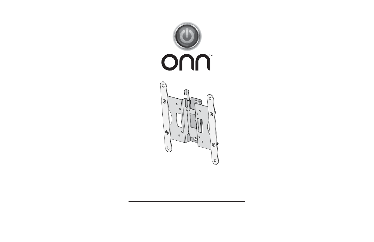
13-32” Tilting TV Wall Mount
Model: ONA16TM008
PRODUCT GUIDE
Page 2
IMPORTANT SAFETY INSTRUCTIONS – SAVE THESE INSTRUCTIONS – PLEASE READ ENTIRE MANUAL PRIOR TO USE
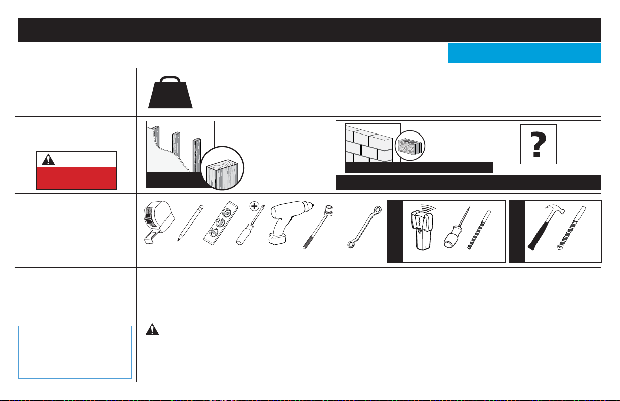
Before getting started, let’s make sure this mount is perfect for you!
Does your TV
1
(including accessories)
weigh more than
25 lb (11.3 kg)?
What is your
2
wall made of?
CAUTION:
DO NOT install
into drywall alone
Do you have
3
all the tools
needed?
Ready to begin?
4
We’ll Make It Stress-Free
If you have any questions,
just give us a call.
877-689-1665.
We’re ready to help!
2
25 lb
(11.3
kg)
Perfect!
Tape
Measure
Please read through these instructions completely to be sure you’re comfortable with this easy install process.
Also check your TV owner’s manual to see if there are any special requirements for mounting your TV.
If you do not understand these instructions or have doubts about the safety of the installation, assembly or use
of this product, contact Customer Service at 87
Pencil Level
CAUTION: Avoid potential personal injuries and property damage!
● This product is designed for use in wood stud, solid concrete, and concrete block walls - DO NOT install into drywall alone
● The wall must be capable of supporting fi ve times the weight of the TV and mount combined
● Do not use this product for any purpose not explicitly specifi ed by manufacturer
● Manufacturer is not responsible for damage or injury caused by incorrect assembly or use
No — Perfect!
Yes — This mount is NOT compatible. Call 877-689-1665 to fi nd a compatible mount.
Drywall with
wood studs?
Concrete Kit required (not included)
Call Customer Service: 877-689-1665
7/16 in.
(12 mm)
Socket
Wrench
Wrench
Screwdriver
Electric
Drill
7-689-1665.
3/8 in.
(10 mm)
Solid concrete or
concrete block?
Stud Finder
Wood Stud Install
Para Español ver página 16
Unsure?
1/8 in.
(3 mm)
Awl
Wood
Drill Bit
Concrete Install
Hammer
3/8 in.
(10 mm)
Concrete
Drill Bit
Page 3
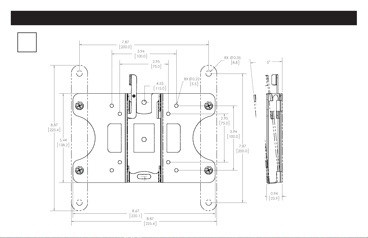
Dimensions
in.
[mm]
TILT
3
Page 4
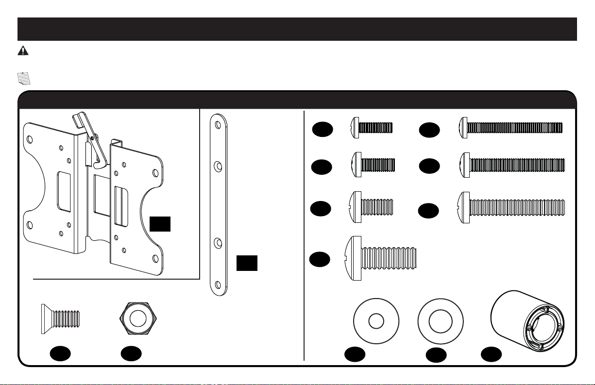
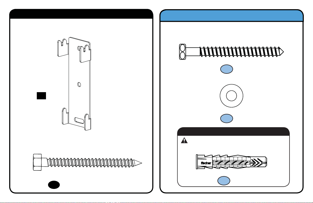
Supplied Parts and Hardware
M4 x 12mm
M5 x 12mm
M6 x 12mm
M6 x 35mm
M5 x 35mm
M4 x 35mm
M6 x 14mm
M6
22mm
M4 / M5
M6 / M8
M8 x 20mm
WARNING: This product contains small items that could be a choking hazard if swallowed. Before starting assembly, verify all parts are included and
undamaged. If any parts are missing or damaged, do not return the damaged item to your dealer; contact Customer Service. Never use damaged parts!
NOTE: Not all hardware included will be used.
Parts and Hardware for STEP 1
TV Screws
05 x4
09 x4
(Extension Bracket)
4
Screws
*
03 x4 04 x4
Nuts
(Extension Bracket)
TV Bracket
01 x1
†
*
TV Bracket
Extenders
*
02 x2
Only needed for TVs with
*
20.0 x 20.0 cm (7 7/8 x 7 7/8 in.)
hole patterns
Nylon locking bracket nuts
†
are poly-locks and will need
to be forcibly tightened.
06 x4
07 x4
08 x4
10 x4
11 x4
12 x4 14 x4
Washers
13 x4
Spacers
Page 5
1/4 x 2¾ in.
Parts and Hardware for STEP 2
Wall Plate
x1
15
Lag Bolts
Concrete Installation Kit (not included)
Contact Customer Service at 877-689-1665 to have these
additional pieces shipped directly to you.
1/4 x 2½ in.
x2
C1
1/4 in.
x2
C2
R
For concrete installations ONLY
CAUTION: Do not use in drywall or wood
Concrete Anchors
16
x2
Fischer UX 10 x 60R Anchor
x2
C3
5
Page 6
STEP 1 Attach TV Bracket to TV
cm
inches
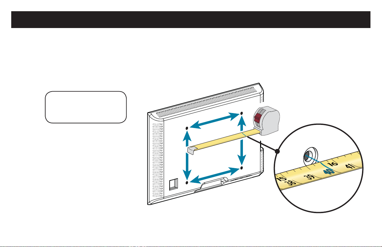
1.1 Measure Your TV Hole Pattern
Measure the width and height of your TV hole pattern in cm.
Record your measurements:
Width __________ cm x Height ________ cm
75 mm = 7.5 cm ≈ 3 in.
100 mm = 10 cm ≈ 4 in.
200 mm = 20 cm ≈ 7 7/8 in.
inch dimensions are approximate
W
H
6
Page 7

1.2 Assemble Your TV Bracket
Determine which TV bracket configuration to use, A or B, based
on your TV hole pattern measurements (W x H) from STEP 1.1.
B
TV Hole Pattern
Measurement
20.0 x 20.0
Dimensions in cm
20.0
A
Dimensions in cm
TV Hole Pattern
Measurement
7.5 x 7.5
10.0 x 10.0
20.0 X 10.0
02
03
04
These smaller hole patterns only use TV bracket 01.
Do not use the two TV bracket extenders
and four nuts 04.
10.0
7.5
02
and four screws
20.0
01
7.5
10.0
03
02
Assemble TV bracket extenders
Secure using four screws 03 and four nuts
NOTE: Nuts 04 are poly-locks and need to be forcibly tightened.
04
3/8 in. (10 mm)
wrench
02
onto TV bracket
02
03
03
01
as illustrated.
04
in the corner holes shown.
20.0
01
02
7
Page 8

1.3 Select TV Screw Diameter 1.4 Select TV Screw Length
Hand thread screws into the threaded inserts
on the back of your TV to determine which
screw diameter (M4, M5, M6 or M8) to use.
M5 M6 M8M4
If your TV has a flat back AND you want your TV closer to
the wall, use the shorter screws (a).
Use the spacers and longer screws (b) to accommodate:
● Round/irregular back TVs
● TVs with inset mounting holes
● Extra space needed for cables
a
FLAT BACK ROUND BACK CABLESINSET HOLES
b
Standard configurations
are shown. For special
applications, or if you
are uncertain about your
hardware selection,
contact Customer Service
at 877-689-1665.
CAUTION:
Verify adequate thread
engagement with your screw/
washer/spacer combination
AND TV bracket (STEP 1.5).
- Too short will not hold the TV.
- Too long will damage the TV.
Too Short
Correct
Too Long
8
Page 9

1.5 Attach TV Bracket
Position your TV bracket configuration over your TV hole pattern - making sure the brackets are vertically centered and level.
Install using either the screw/washer (a: Flat Back) or screw/washer/spacer (b: Round Back / Extra Space) combination you selected for your TV.
CAUTION: Avoid potential personal injuries and property damage! DO NOT use power tools for this step. Tighten the screws only enough
to secure the TV bracket to the TV. DO NOT overtighten the screws.
IMPORTANT: Ensure TV bracket is securely fastened before moving on to the next step.
TV Bracket Confi guration
(from page 7)
Illustrated with spacers
02
01
B
Flat Back
a
0509061007 08
121213
Round Back / Extra Space
b
01
TV Bracket Confi guration
(from page 7)
Illustrated with spacers
11
14
A
13
9
Page 10

STEP 2A Attach Wall Plate
CAUTION: Avoid potential personal injury or property damage!
• Drywall covering the wall must not exceed 5/8 in. (16 mm)
• Minimum wood stud size: common 2 x 4 in. (51 x 102 mm) nominal 1½ x 3½ in. (38 x 89 mm)
1. Locate your stud. Verify and mark the center of the stud by finding the stud edges using an awl, a thin nail, or an edge to edge stud finder.
2. Position the wall plate 15 at your desired height and line up the holes with your stud center line. Level the mark the two hole locations.
3. Drill two pilot holes using a 1/8 in. (3 mm) diameter drill bit.
IMPORTANT: Pilot holes must be drilled to a depth of 2 3/4 in. (69.8 mm). Be sure to drill into the center of the stud.
1
≤ 5/8 in.
(16 mm)
2
Wood Stud Installation
2¾ in. (69.8 mm)
3
1/8 in.
(3 mm)
15
10
Page 11

4. Install wall plate
CAUTION: Avoid potential personal injury or property damage! All four lag bolts 16 MUST BE firmly tightened to prevent unwanted
movement of the wall plate
NOTE: If needed, you can make small level adjustments to the wall plate by loosening the bottom lag bolt and shifting the wall plate until level.
Tighten the bottom lag bolt
Go to STEP 3 on PAGE 14.
15
using two lag bolts 16. Tighten the lag bolts only until they are pulled firmly against the wall plate.
Ensure the wall plate is securely fastened to the wall before continuing on to the next step.
15.
16
when adjustments are complete.
4
15
16
15
16
11
Page 12

STEP 2B Attach Wall Plate
Solid Concrete or Concrete Block Installation
CAUTION: Avoid potential personal injury or property damage!
• Mount the wall plate
• Minimum solid concrete thickness: 8 in. (203 mm)
• Minimum concrete block size: 8 x 8 x 16 in. (203 x 203 x 406 mm)
1. Position the wall plate 15 on the wall at your desired height. Level the wall plate and mark the two hole locations.
2. Drill two pilot holes using a 3/8 in. (10 mm) diameter masonry drill bit.
IMPORTANT: Pilot holes must be drilled to a depth of 3 in. (75 mm). Never drill into the mortar between blocks.
1
15
directly onto the concrete surface
2
Concrete Installation Kit is not included
(see page 5) Contact Customer Service at
877-689-1665 to have the additional hardware
shipped directly to you.
15
3 in. (75 mm)
3/8 in.
(10 mm)
12
Page 13

3. Insert two anchors C3 (Fischer UX 10 x 60R - included in the Concrete Installation Kit *).
CAUTION: Be sure the anchors are seated flush with the concrete surface.
4. Install wall plate
CAUTION: Avoid potential personal injury or property damage! All four lag bolts C1 MUST BE firmly tightened to prevent unwanted
movement of the wall plate
NOTE: If needed, you can make small level adjustments to the wall plate by loosening the bottom lag bolt C1 and shifting the wall plate until level.
Tighten the bottom lag bolt C1 when adjustments are complete.
Contact Customer Service at 877-689-1665 to have the Concrete Installation Kit shipped directly to you.
*
15
using two lag bolts C1. Tighten the lag bolts only until they are pulled firmly against the wall plate 15.
Ensure the wall plate 15 is securely fastened to the wall before continuing on to the next step.
15.
43
C1
15
C3
C1
*
13
Page 14

STEP 3 Hang TV onto Wall Plate
HEAVY! You may need
assistance with this step.
1
01
IMPORTANT: The locking tab needs
to be in the unlocked position before
attaching the TV to the wall plate.
2
01
15
Hang your TV in either the TILT or LOW PROFILE
positions, depending on preference.
TILT
POSITION
15
LOW PROFILE
POSITION
15
14
Page 15

3
TV Adjustments
REMOVING THE TV:
Remove any cables from the TV.
Move the locking tab into the unlocked position and
lift the TV up and out away from the wall plate.
01
15
01
15
CAUTION: Avoid potential personal injuries and property
damage! Once the TV is on the wall plate, move the locking
tab to the locked position to secure the TV onto the wall plate.
15
Page 16

ESPAÑOL
CONSÉRVELAS. LEA TODO EL MANUAL ANTES DE UTILIZAR ESTE PRODUCTO.
INSTRUCCIONES DE SEGURIDAD IMPORTANTES.
Antes de comenzar, verifiquemos que este soporte sea el ideal para sus necesidades.
¿Su televisor pesa
1
más de 11,3 kg (25
libras), incluidos
los accesorios?
11,3 kg
(25
lb)
No — ¡Perfecto!
Sí — Este soporte NO es compatible. Llame al 877-689-1665 para encontrar un soporte compatible.
¿De qué está
2
hecha su pared?
PRECAUCIÓN:
NO lo instale en
tabiques únicamente
de yeso
¿Tiene
3
todas las
herramientas
necesarias?
¿Listo para
4
comenzar?
16
¿Tabiques de yeso
con montantes de
madera?
e requiere el kit para Hormigón (no incluido)
¡Perfecto!
DestornilladorCinta métrica Broca
Lea estas instrucciones en su totalidad para estar seguro de sentirse cómodo con este fácil proceso de instalación. Consulte
también el manual del usuario de su televisor para ver si existe algún requisito especial para instalar su televisor en la pared.
Si no entiende las instrucciones o si tiene dudas acerca de la seguridad de la instalación, del ensamblado o del uso del
producto, póngase en contacto con el servicio de atención al cliente al 877-689-1665.
Taladro
eléctrico MartilloLlave de tubo Llave
Llame al 877-689-1665
12 mm
(7/16”)
10 mm
(3/8 in.)
Paredes con
montantes de madera
¿Hormigón sólido o
bloques de cemento?
Localizador
de montantes
PunzónLápiz Nivel
3 mm
(1/8'')
Madera
¿No está
seguro?
10 mm
(3/8'')
hormigón
paredes con de
Hormigón
Broca
PRECAUCIÓN: Evite posibles lesiones personales y daños materiales.
● Este producto incluye instrucciones y elementos de sujeción para su instalación en paredes con montantes de madera,
en superficies de hormigón y sobre bloques de cemento. NO lo instale en tabiques únicamente de yeso.
● La pared debe soportar cinco veces el peso del televisor y del soporte juntos.
● No utilice este producto para ningún otro propósito que no sea el explícitamente especificado por el fabricante.
● El fabricante no se responsabiliza por ningún daño o lesión resultante del montaje incorrecto o de uso indebido.
Page 17

Piezas y accesorios suministrados
Ver pagina 4
ESPAÑOL
ADVERTENCIA: Este producto contiene piezas pequeñas que, si fuesen tragadas, podrían producir asfixia.
Antes de iniciar el ensamblaje, compruebe que todas las piezas estén incluidas y en buenas condiciones. Si faltan piezas o alguna está dañada,
no devuelva el artículo al distribuidor; póngase en contacto con el servicio de atención al cliente. Nunca utilice piezas deterioradas.
NOTA: No todos los accesorios incluidos deberán utilizarse.
El Kit de instalación en hormigón no está incluido Comuníquese con el servicio de atención al cliente al 877-689-1665 para solicitar que le
enviemos los elementos de sujeción adicionales.
SOLO para instalaciones en hormigón
PRECAUCIÓN: No usar en placas de yeso o montantes de madera
PASO 1 Fijar la placa de sujeción al televisor
C3
x4
UX10 x 60R
Ver pagina 6
1,1 Mida el patrón de orificios del televisor
Mida en mm el ancho y el alto del patrón de orificios del televisor.
Anote las medidas: Ancho_____________cm x Alto______________cm
1,2 Arme la placa de sujeción del televisor
Determine qué configuración de placa de sujeción debe usar (A o B) según las medidas del patrón de orificios del televisor.
Los patrones de orificios más pequeños solo requieren placa de sujeción 01.
A
No utilice las cuatro extensiones de la placa de sujeción
Ensamble las extensiones
B
Fije colocando ocho tornillos 03 en los orificios de las esquinas que se muestran en la imagen.
02
de la placa de sujeción y la placa de sujeción
02
ni los ocho tornillos 03.
01
tal como se muestra en la ilustración.
1,3 Seleccione el diámetro de los tornillos para el televisor
Enrosque manualmente los tornillos en los encastres roscados del dorso del televisor a fin de determinar qué diámetro de tornillos (M4, M5, M6 o M8) utilizar.
17
Page 18

ESPAÑOL
Si el dorso del televisor es plano, utilice los tornillos cortos. Los espaciadores y los tornillos largos se proporcionan para:
televisores con dorso irregular o redondeado • televisores con orificios de montaje intercalados • dejar un espacio adicional para cables
•
1,4 Seleccione el largo de los tornillos para el televisor
PRECAUCIÓN: Verifique el enrosque adecuado de la combinación tornillo/arandela/espaciador y el soporte del televisor (Ver PASO 1,5).
- Si el tornillo es demasiado corto, no sostendrá el televisor.
- Si es demasiado largo, dañará el televisor.
1,5 Fije la placa de sujeción
Posicione la placa de sujeción armada sobre el patrón de orificios del televisor y verifique que esté centrada y nivelada verticalmente.
Instale las placas de sujeción usando la combinación que haya seleccionado para su televisor: tornillo corto y arandela o espaciador, o bien tornillo largo y arandela.
PRECAUCIÓN: Evite posibles lesiones personales y daños materiales. NO use herramientas eléctricas para este paso. Apriete los
tornillos sólo lo suficiente para asegurar el soporte de TV al televisor. No apriete excesivamente los tornillos.
IMPORTANTE: Asegúrese la placa de sujeción esté bien sujetas antes de continuar.
PASO 2A Fijar la placa mural
PRECAUCIÓN: Evite lesiones y daños materiales.
● El yeso que recubre la pared no debe exceder los 16 mm (5/8'').
● Tamaño mínimo del montante de madera: común 51 mm x 102 mm (2'' x 4''); nominal 38 mm x 89 mm (1½'' x 3½'').
1. Localice un montante. Busque los bordes del montante y marque el centro con un punzón o un clavo delgado, o bien utilice un detector de
bordes de montantes.
2. Ubique la placa mural 15 a la altura deseada y alinee los orificios con la línea central de los montantes. Nivele y marque la ubicación de los orificios.
3. Con una mecha de 3 mm (1/8'') de diámetro, realice los orificios guía.
IMPORTANTE: Los orificios guía deben realizarse hasta una profundidad de 69.8 mm (2 3/4''). Asegúrese de perforar el centro del montante.
4. Ajuste los tornillos tirafondo 16 solamente hasta que queden firmes contra la placa mural
PRECAUCIÓN: Evite posibles lesiones personales y daños materiales. Los cuatro tornillos tirafondo
que la placa mural se desplace
Continúe con el PASO 3 en la PÁGINA 14.
18
15
. Asegúrese de que la placa mural está fijada con seguridad a la pared antes de proceder con el siguiente paso.
Montantes de madera
15
.
16
DEBEN ESTAR apretados firmemente para evitar
Ver pagina 10
Page 19

PASO 2B Fijar la placa mural
PRECAUCIÓN: Evite lesiones y daños materiales.
● Instale el módulo de la placa mural
● Espesor mínimo del hormigón: 8 pulgadas (203 mm)
● Tamaño mínimo del bloque de cemento: 8 x 8 x 16 pulgadas (203 x 203 x 406 mm)
1. Coloque la placa mural 15 en la pared a la altura que desee.
Nivele la placa mural y marque la ubicación de los orificios.
2. Realice los orificios guía con una mecha para mampostería de 3/8’’ (10 mm) de diámetro.
IMPORTANTE: Los orificios guía deben realizarse hasta una profundidad de 3’’ (75 mm). Nunca perfore el cemento que une los bloques.
3. Introduzca tres anclajes C3 (Fischer UX 10 x 60R - incluidos en el Kit de instalación en hormigón *).
PRECAUCIÓN: Cerciórese de que los anclajes queden nivelados respecto de la superficie de hormigón.
4. Instale el módulo de la placa mural 15 usando dos tornillos tirafondo C1. Ajuste los tornillos tirafondo solamente hasta que queden firmes
contra la placa mural.
15
directamente sobre la superficie de hormigón
Hormigón sólido o bloques de cemento
Ver pagina 12
El Kit de instalación en hormigón no está
incluido (Ver página 5) Comuníquese con el
servicio de atención al cliente al 877-689-1665
para solicitar que le enviemos los elementos de
sujeción adicionales.
ESPAÑOL
PRECAUCIÓN: Evite posibles lesiones personales y daños materiales. Los cuatro tornillos tirafondo
evitar que la placa mural
15
se desplace. Asegúrese de que la placa mural
15
está fijada con seguridad a la pared antes de proceder con el siguiente paso.
C1
DEBEN ESTAR apretados firmemente para
* Comuníquese con el servicio de atención al cliente al 877-689-1665 para solicitar que le enviemos el Kit de instalación en hormigón .
PASO 3 Colgar el televisor en la placa mural
¡ELEMENTO PESADO! Es posible que necesite ayuda en este paso.
1. IMPORTANTE: La pestaña de bloqueo necesita estar liberada antes de fijar el televisor a la placa mural.
2. Colgar el televisor, ya sea en el TILT o posiciones DE PERFIL BAJO.
3. PRECAUCIÓN: Evite posibles lesiones personales y daños materiales. Una vez que el televisor se encuentra en la placa mural, la
pestaña de bloqueo debe estar en la posición de bloqueo.
Ajustes del televisor
RETIRAR EL TELEVISOR: Libere la pestaña de bloqueo y levante el televisor y retírelo de la placa mural.
Ver pagina 14
Ver pagina 15
19
Page 20

For Customer Service, Please Call:
877-689-1665
©2016 Wal-Mart Stores, Inc. Onn is a registered trademark of Wal-Mart Stores, Inc. All Rights Reserved.
MADE IN CHINA
Distributed by Wal-Mart Stores, Inc. Bentonville, AR 72716
6901-002573 00
 Loading...