

Page 1

Power Wave 4
Emergency Lighting Inverter (ELI)
10 – 160 KVA
*200 - 500 KVA
User Manual
Installation
Operation
Maintenance
Doc #. 6005-145
Rev. A
Due to continuous product improvement this document is subject to change without prior notice.
Page 2
CAUTION!
HAZARDOUS VOLTAGE EXISTS INSIDE THE ELI (INCLUDES THE
CONNECTION TERMINALS). CABLE CONNECTION AND MAINTENANCE
SHOULD BE DOBE BY PROFESSIONAL OR QUALIFIES PERSONNEL.
THE ELI HAS ITS OWN INTERNAL POWER SOURCE (BATTERIES). THE
OUTPUT TERMINALS MAY BE LIVE EVEN WHEN THE ELI IS NOT CONNECTED
TO THE AC SUPPLY.
DC CAPACITORS ARE EMPLOYED IN THIS UNIT. HAZARDOUS VOLTAGE
STILL EXITS EVEN WHEN THE UNIT IS NOT ENERGIZED. DO NOT TOUCH ANY
PART OF THE INSIDE OF THE ELI.
WARNING!
BE SURE TO OPERATE THE ELI WITHIN THE RATED POWER LEVEL.
PREVENT DIRECT EXPOSURE TO DIRECT SUNLIGHT, RAIN OR
CONTAMINATING ENVIRONMENT.
ONLY QUALIFIED TECNICIANS SHOULD REPLACE THE BATTERIES. SINCE
BATTERIES HAVE HIGH SHORT-CIRCUIT CURRENT CAPACITY, MISTAKES IN
CONNECTION OR DISCONNECTION CAN CAUSE SEVERE BURS OR DEATH
TO SERVICING PERSONNEL.
6005-145 Rev. A a
Page 3

TABLE OF CONTENTS
CONTENTS …………………………………………….……………………….……………………….Page
SAFETY
1.
SYSTEM OVERVIEW
1.1. Construction of the ELI ............................................................................................................................... 1-1
1.2. Features and Advantages............................................................................................................................. 1-5
1.3. Rectifier ....................................................................................................................................................... 1-8
1.4. Inverter ....................................................................................................................................................... 1-10
1.5. Static Switch ..............................................................................................................................................1-11
1.6. Maintenance Bypass ................................................................................................................................. 1-12
1.7. Main Input Circuit Breaker ....................................................................................................................... 1-12
1.8. Main Output Circuit Breaker .................................................................................................................... 1-12
1.9. Battery Circuit Breaker ............................................................................................................................. 1-12
..................................................................................................................... a
............................................................................................. 1-1
1.10 Battery ....................................................................................................................................................... 1-12
1.11 Single Line Diagram (120/208Y) ............................................................................................................ 1-13
1.12 Single Line Diagram (277/480Y) ............................................................................................................ 1-14
1.13 Dimensions & Drawings .......................................................................................................................... 1-15
1.14 Front Panel ................................................................................................................................................ 1-21
2.
TECHNICAL SPECIFICATION
2.1. Specification for 208/120V Unit ............................................................................................................................... 2-1
2.2. Specification for 480/277V Unit ............................................................................................................................... 2-2
2.3 Model Number Chart .................................................................................................................................... 2-3
3.
INSTALLATION
3.1. Site & Environment Consideration ............................................................................................................ 3-1
3.2. Unpacking .................................................................................................................................................... 3-4
3.3. Cable Selection ............................................................................................................................................ 3-5
3.4. Input/Output Protective Device Rating Chart ............................................................................................ 3-6
3.5. Terminal Connection ................................................................................................................................... 3-7
4.
OPERATIONS
............................................................................................................................................. 3-1
.................................................................................................................................................. 4-1
................................................................................................. 2-1
4.1. Start-up Procedure ....................................................................................................................................... 4-1
4.2. Shutdown Procedure .................................................................................................................................... 4-2
4.3. From Inverter to Maintenance Bypass Procedure ..................................................................................... 4-3
4.4. From Maintenance Bypass to Inverter Procedure ..................................................................................... 4-4
4.5.
Green mode selection
6005-145 Rev. A b
.................................................................................................................................... 4-5
Page 4

CONTENTS ................................................................................................................................................. Page
5.
LCD DISPLAY
5.1. Menu 0 – Main Menu ................................................................................................................................ 5-1
5.2. Menu 1 – Select Menu .............................................................................................................................. 5-2
5.3. Menu 2 – Status / Warning Menu .................................................................................................................... 5-3
5.4. Menu 3 – Real Time Data Menu ...................................................................................................................... 5-4
5.5. Menu 4 – Historical Event Menu .............................................................................................................. 5-5
5.6. Menu 5 – Parameter Setting Menu ........................................................................................................... 5-6
5.7. Menu 6 – Rectifier Data Menu .................................................................................................................. 5-7
5.8. Menu 7 – Output Data Menu ..................................................................................................................... 5-8
5.9. Menu 8 – Other Data Menu ....................................................................................................................... 5-8
5.10. Menu 9 – Reserve Data Menu ......................................................................................................................................... 5-9
5.11. Menu 10 – Boost Charge Setting Menu ................................................................................................................ 5-9
5.12. Menu 11 – Data Time Setting Menu ........................................................................................................................... 5-11
5.13. Menu 12 – Other Setting Menu ........................................................................................................................... 5-12
.................................................................................................................................. 5-1
6.
INTERFACE CONNECTIONS
6.1. Dry Contacts .............................................................................................................................................. 6-1
6.2. External Shutdown ..................................................................................................................................... 6-4
6.3. DB9 Connection ......................................................................................................................................... 6-4
7.
OPTIONS
7.1. Emergency Power Off Switch (EPO) ....................................................................................................... 7.1
7.2. Remote Control Panel ................................................................................................................................ 7.1
7.3. Software for PC Monitoring ...................................................................................................................... 7.2
7.4. Auto Dialing Module ................................................................................................................................. 7.2
7.5. Battery Monitoring Module - DCMAN .................................................................................................... 7.2
7.6. Input Transient Voltage Surge Suppressor (TVSS) ................................................................................. 7.2
7.7. Web/SNMP Card ........................................................................................................................................ 7.3
7.8. Output AUX Circuit Breakers ................................................................................................................... 7.3
7.9. Higher Kaic Circuit Breakers .................................................................................................................... 7.3
7.10. Delta Input ................................................................................................................................................ 7.3
................................................................................................ ..................................... 7-1
................................................................................................ .. 6-1
7.11. Dual Input ................................................................................................................................................. 7.3
7.12. Seismic Bracket. ....................................................................................................................................... 7.3
7.13. Factory Set Green Mode .......................................................................................................................... 7.3
7.14. Battery Cabinet and Battery run time...................................................................................................... 7. 4
7.15. Battery Cabinet Arrangement Drawings ................................................................................................. 7.6
7.16. Replaceable Parts List ............................................................................................................................ 7.11
6005-145 Rev. A c
Page 5

CONTENTS ................................................................................................................................................. Page
8.
REDUNDANCY
8.1. Serial Redundancy ....................................................................................................................................... 81
8.2. Parallel Redundancy .................................................................................................................................. 8-4
9.
MAINTENANCE
9.1. Safety and Precautions .............................................................................................................................. 9-1
9.2. When to call ............................................................................................................................................... 9-3
9.3. Step to take ................................................................................................................................................. 9-3
9.4. Preventive Maintenance ............................................................................................................................ 9-4
9.4.1 Maintenance Log ..................................................................................................................................... 9-4
9.4.2 Periodic Testing of Unit .......................................................................................................................... 9-5
.............................................................................................................................................. 8-1
............................................................................................................................................ 9-1
9.4.3 Maintaining Batteries .............................................................................................................................. 9-5
9.4.4 Battery Cabinets ...................................................................................................................................... 9-7
9.4.5 Power Connections .................................................................................................................................. 9-7
9.4.6 Battery Terminals .................................................................................................................................... 9-8
9.5. Online Power Customer Service and Support ......................................................................................... 9-8
9.5.1 Start-Up Services ..................................................................................................................................... 9-8
9.5.2 Maintenance Agreements........................................................................................................................ 9-8
9.5.3 Warranties ................................................................................................................................................ 9-8
9.5.4 Help .......................................................................................................................................................... 9-9
Appendix A
Battery Exerciser setting ................................................................................................................................ 9-15
6005-145 Rev. A d
Page 6

OnLine Power, Inc.
Reproduction or Distribution forbidden
NOTICE: THIS DOCUMENT CONTAINS PROPRIETARY
INFORMATION
This document contains proprietary and confidential information of
OnLine Power, Inc. (”OnLine Power”). In consideration of the
receipt of this document, the recipient agrees not to copy any of its
contents, nor to disclose them to or allow them to be used by any
person not currently an OnLine Power employee or an employee of
the recipient having a need to know, without the express written
consent of OnLine Power, and further agrees to surrender this
document to OnLine Power when the reason for its receipt has
terminated. Due to continuous product improvement this document
is subject to change without prior notice.
© 2009 OnLine Power, Inc. – All rights reserved
6005-145 Rev. A e
Page 7

Serial Number:
KVA/Power Rating:
Input Voltage:
Output Voltage:
Manufacturer Date:
Congratulations on selecting one of the fine products from OnLine Power, the leader in
power protection technology. Our wide product offering includes UPS (Uninterruptible
Power Systems), power conditioners, automatic voltage regulators and specialty
transformers (e.g., computer-grade, medical-grade). Since our founding in 1972, OnLine
Power has shipped many of these fine products to discerning customers around the world
for use on sensitive equipment and in critical applications.
One of our goals is to make our manuals both comprehensive and easy to use. The new
format of our user manual is the result of ideas and inputs from customers like you who
have taken an active interest in our continued success. We invite and appreciate your
feedback on our products and documentation via e-mail, fax, mail, or telephone.
HEADQUARTERS
OnLine Power
5701 Smith Street
Commerce, CA 90040
SALES
Phone: (800) 227-8899
FAX No: (323) 721-5017
E-mail: [email protected]
Office Hours are 7:00 AM to 5:00 PM PST
SERVICE
If you require assistance, please call our 24-hour toll free hot line 800-PWR-
SRVC (800-797-7782) or email to [email protected]. Please have the
following information from your unit’s nameplate available to speed
assistance:
Due to continuous product improvement this document is subject to change without prior notice.
6005-145 Rev. A f
Page 8
Danger!
ONLY FACTORY TRAINED OR AUTHORIZED PERSONNEL SHOULD ATTEMPT
TO INSTALL OR REPAIR THE UNIT OR ITS BATTERY SYSTEM. IMPROPER
INSTALLATION HAS PROVEN TO BE THE SINGLE MOST SIGNIFICANT CAUSE
OF START-UP PROBLEMS. HIGH AC AND DC ELECTRICAL VOLTAGES ARE
PRESENT THROUGHOUT THE UNIT (S) AND INCORRECT INSTALLATION OR
SERVICING COULD RESULT IN ELECTROCUTION, FIRE, EXPLOSION, OR
EQUIPMENT MALFUNCTION.
Danger!
READ THIS MANUAL IN ITS ENTIRETY BEFORE PERFORMING
INSTALLATION, START-UP, OPERATION, AND MAINTENANCE OF THE UNIT
OR BATTERY SYSTEMS. FAILURE TO DO SO COULD RESULT IN
ELECTROCUTION, FIRE, EXPLOSION, OR EQUIPMENT MALFUNCTION.
Caution
SAFETY
Following safety precautions is important when operating or servicing electrical
equipment. The symbols shown are used extensively throughout this manual.
Always heed these precautions since they are essential to the safe operation and
servicing of this product.
Boxes labeled with the “ Danger!” symbol indicate that there is a high risk of
personal injury or death if instructions are not followed.
Warnings labeled with the symbol indicate that there is a high
probability of equipment malfunction, damage, or destruction if instructions are not
followed.
6005-145 Rev. A g
Page 9
Danger!
EXERCISE EXTREME CARE WHEN HANDLING UNIT AND BATTERY
CABINETS TO AVOID EQUIPMENT DAMAGE OR INJURY TO PERSONNEL.
CABINETS WEIGH SEVERAL HUNDRED POUNDS.
Danger!
ALL POWER CONNECTIONS MUST BE COMPLETED BY A LICENSED
ELECTRICIAN WHO IS EXPERIENCED IN WIRING THIS TYPE OF EQUIPMENT.
WIRING MUST BE INSTALLED IN ACCORDANCE WITH ALL APPLICABLE
NATIONAL AND LOCAL ELECTRICAL CODES. IMPROPER WIRING MAY
CAUSE DAMAGE TO THE EQUIPMENT, INJURY OR DEATH OF PERSONNEL.
VERIFY THAT ALL HIGH AND LOW VOLTAGE INPUT POWER CIRCUITS ARE
DE-ENERGIZED AND LOCKED OUT BEFORE INSTALLING CABLES OR
MAKING ANY ELECTRICAL CONNECTIONS.
Danger!
OBSERVE ALL BATTERY SAFETY PRECAUTIONS DURING INSTALLATION
OR SERVICE OF THE UNIT OR BATTERIES. EVEN WITH THE BATTERY
CIRCUIT BREAKER IN THE OFF POSITION, THE DANGER OF
ELECTROCUTION MAY STILL BE PRESENT. THE BATTERY POWER TO THE
UNIT MUST BE LOCKED AND TAGGED “OFF” BEFORE PERFORMING ANY
SERVICE OR WORK ON THE UNIT. THE BATTERY MANUFACTURER’S
SAFETY INFORMATION AND MATERIAL SAFETY DATA SHEET IS LOCATED
IN A POCKET ATTACHED TO THE INSIDE OF LEFT DOOR OF EACH UNIT.
FAILURE TO FOLLOW INSTRUCTION LISTED ABOVE AND ELSEWHERE IN
THIS MANUAL COULD RESULT IN AN EXPLOSION, FIRE, EQUIPMENT
MALFUNCTION, OR ELECTROCUTION.
Danger!
TEST LIFT AND BALANCE THE CABINETS BEFORE MOVING. MAINTAIN
MINIMUM TILT FROM VERTICAL AT ALL TIMES. THE BOTTOM STRUCTURE
WILL SUPPORT THE UNIT ONLY IF THE FORKLIFT FORKS ARE
COMPLETELY UNDERNEATH THE UNIT.
6005-145 Rev. A h
Page 10
Danger!
ALL POWER TO THE UNIT MUST BE LOCKED AND TAGGED “OFF” BEFORE
PERFORMING ANY SERVICE OR WORK ON THE UNIT. FAILURE TO DO SO
COULD RESULT IN ELECTROCUTION.
Danger!
EXTREME CAUTION IS REQUIRED WHEN PERFORMING MAINTENANCE.
LETHAL VOLTAGES EXIST WITHIN THE EQUIPMENT DURING OPERATION.
OBSERVE ALL WARNINGS AND CAUTIONS IN THIS MANUAL. FAILURE TO
COMPLY MAY RESULT IN SERIOUS INJURY OR DEATH. OBTAIN QUALIFIED
SERVICE FOR THIS EQUIPMENT AS INSTRUCTED.
Danger!
BE CONSTANTLY AWARE THAT THE UNIT SYSTEM CONTAINS HIGH DC AS
WELL AS AC VOLTAGES. WITH INPUT POWER OFF AND THE BATTERY,
DISCONNECTED, HIGH VOLTAGE AT THE FILTER CAPACITORS AND POWER
CIRCUITS SHOULD DISCHARGE WITHIN 30 SECONDS. HOWEVER, POWER
CIRCUIT MALFUNCTIONS CAN OCCUR, SO YOU SHOULD ALWAYS ASSUME
THAT HIGH VOLTAGE MIGHT STILL EXIST AFTER SHUTDOWN. VERIFY
THAT POWER IS OFF USING AC AND DC VOLTMETERS BEFORE MAKING
CONTACT.
Danger!
IN A FIRE INVOLVING ELECTRICAL EQUIPMENT, ONLY USE CARBON
DIOXIDE FIRE EXTINGUISHERS, OR THOSE APPROVED FOR USE ON
ELECTRICAL EQUIPMENT. USE OF WATER ON FIRES INVOLVING HIGH
VOLTAGE ELECTRICAL CIRCUITS COULD RESULT IN ELECTROCUTION .
Danger!
SOME COMPONENTS WITHIN THE CABINETS ARE NOT CONNECTED TO
CHASSIS GROUND. ANY CONTACT BETWEEN FLOATING CIRCUITS AND
THE CHASSIS IS A LETHAL SHOCK HAZARD.
6005-145 Rev. A i
Page 11
Danger!
LEAD-ACID BATTERIES CONTAIN HAZARDOUS MATERIALS. BATTERIES MUST BE
HANDLED, TRANSPORTED, AND RECYCLED OR DISCARDED IN ACCORDANCE
WITH FEDERAL, STATE, AND LOCAL REGULATIONS. BECAUSE LEAD IS A TOXIC
SUBSTANCE, LEAD-ACID BATTERIES MUST BE RECYCLED OR DISCARDED AS
HAZADEROUS WAIST.
HARMFUL TO THE SKIN AND EYES AND MAY BE TOXIC.
OF ELECTRICAL SHOCK. THE FOLLOWING PRECAUTIONS SHOULD BE
OBSERVED WHEN WORKING ON BATTERIES:
1. REMOVE WATCHES, RINGS OR OTHER METAL OBJECTS.
2. USE TOOLS WITH INSULATED HANDLES.
3. WEAR RUBBER GLOVES AND BOOTS.
4. DO NOT LAY TOOLS OR METAL PARTS ON TOP OF BATTERIES.
5. DISCONNECT CHARGING SOURCE PRIOR TO CONNECTING OR
DISCONNECTING BATTERY TERMINALS.
6 DETERMINE IF BATTERY IS INADVERTENTLY GROUNDED. IF SO,
REMOVE THE SOURCE OF THE GROUND. CONTACT WITH ANY PART OF
A GROUNDED BATTERY CAN RESULT IN ELECTRICAL SHOCK. THE
LIKELIHOOD OF SUCH SHOCK WILL BE REDUCED IF SUCH GROUNDS
ARE REMOVED DURING INSTALLATION AND MAINTENANCE.
7 LEAD-ACID BATTERIES CAN PRESENT A RISK OF FIRE BECAUSE THEY
GENERATE HYDROGEN GAS. THE FOLLOWING PROCEDURES SHOULD
BE FOLLOWED:
1. DO NOT SMOKE WHEN NEAR BATTERIES.
2. DO NOT CAUSE FLAME OR SPARK IN BATTERY AREA.
8 DISCHARGE STATIC ELECTRICITY FROM YOUR BODY BEFORE
TOUCHING BATTERIES BY FIRST TOUCHING A GROUNDED SURFACE.
Danger!
INTERNAL BATTERY STRAPPING MUST BE VERIFIED BY THE CUSTOMER
PRIOR TO MOVING THIS UNIT.
THIS UNIT CONTAINS NON-SPILLABLE BATTERIES. KEEP THE UNIT
UPRIGHT. DO NOT STACK. DO NOT TIP. ALWAYS FOLLOW THE BATTERY
MANUFACTURER’S SAFETY INFORMATION LOCATED IN A POCKET
ATTACHED TO THE INSIDE OF THE LEFT DOOR OF YOUR UNIT TO PREVENT
AN ACCIDENT THAT COULD RESULT IN INJURY OR DEATH.
6005-145 Rev. A j
................................................................................................. 6-4
Page 12
6005-145 Rev. A 1-1
1. SYSTEM OVERVIEW
1.1. Construction of the ELI
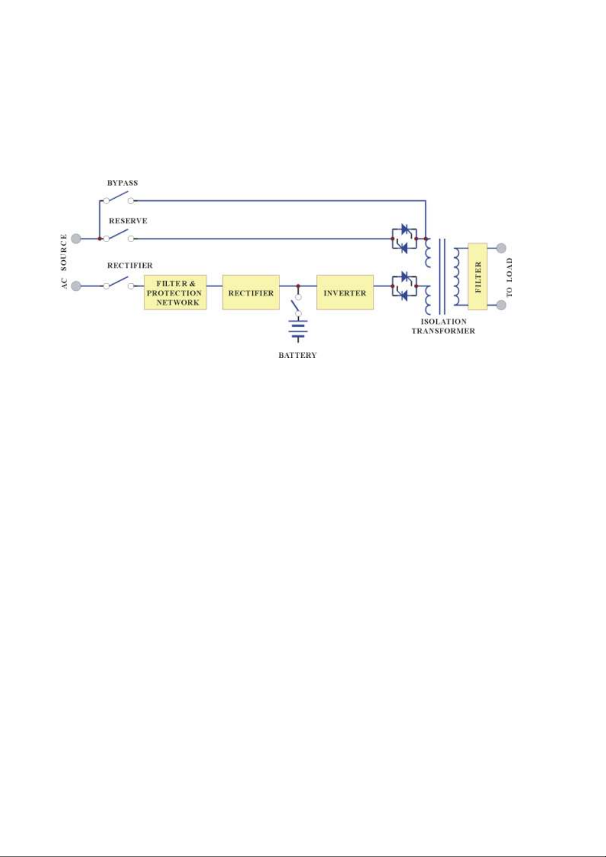
General Topology
The ELI system is composed of input breakers, input filter & protection
network, rectifier, battery bank, inverter, static switch, bypass breaker,
isolation transformer and output filter. The basic topology is shown in the
diagram above. Under normal AC mode, energy from the AC source is
converted to DC power and supplied to the inverter to charge the batteries to its
full capacity all the time, ready to support the output load in case of AC source
failure.
Although the principle and operation of a ELI seems simple and
straightforward, the requirement for a reliable and intelligent ELI makes the
design and manufacturing of a high power ELI one requiring advanced
technology, intelligence, experience and most important, consideration of the
user interface. Many years have been spent in designing the most rugged,
intelligent and reliable ELI for the market, and a safe and convenient ELI for
the user.
Choosing the best and most suitable ELI for a given application can be easy or
difficult, depending on the client’s knowledge of key parameters. The most
obvious specification, output power, depends on the size of the load. Often, an
allowance of 50% more power is added to the present load requirement, both
for tolerance and for future expansion.
Page 13
6005-145 Rev. A 1-2
Another important issue is reliability. The prime aim of a ELI is to protect your
load. Therefore, the ELI should be much more reliable than the AC source. An
unreliable ELI may suffer the problem of frequent break down, even more
frequent than AC failure, and the cost of repair may become more than the cost
of the unit itself.
Generally, there are four different modes of operation, the NORMAL
OPERATION MODE, the BACK-UP (BATTERY) MODE, the RESERVE
MODE and the MAINTENANCE BYPASS MODE. These are explained
below.
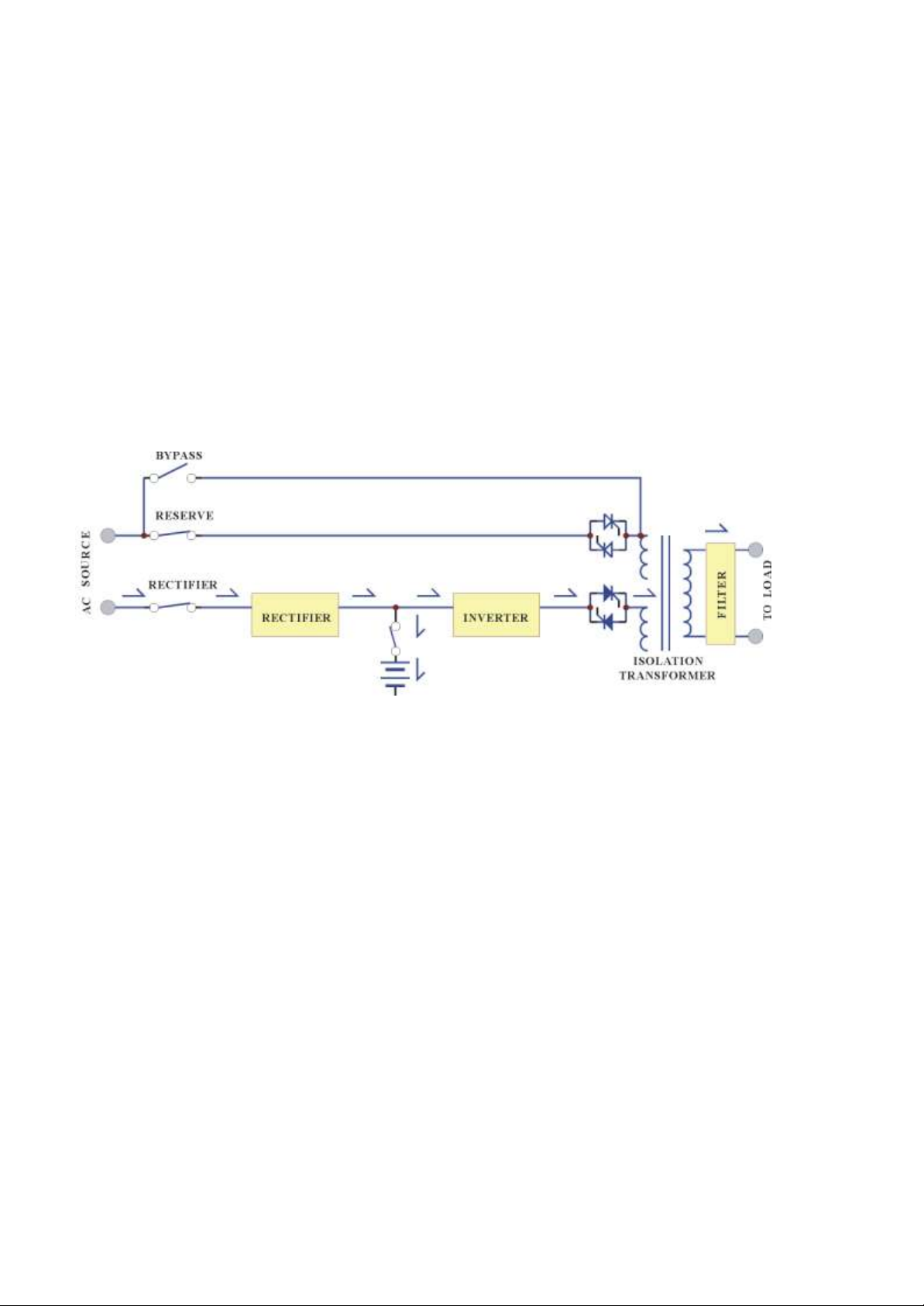
Normal Operation Mode:
The rectifier converts the AC input to DC power to supply the inverter and
charge the batteries simultaneously. All the fluctuations, surges and spikes of
the AC input are removed during AC to DC conversion. Therefore, the AC
supplied by the inverter is clean and stable.
Page 14
6005-145 Rev. A 1-3
Back-up Mode:
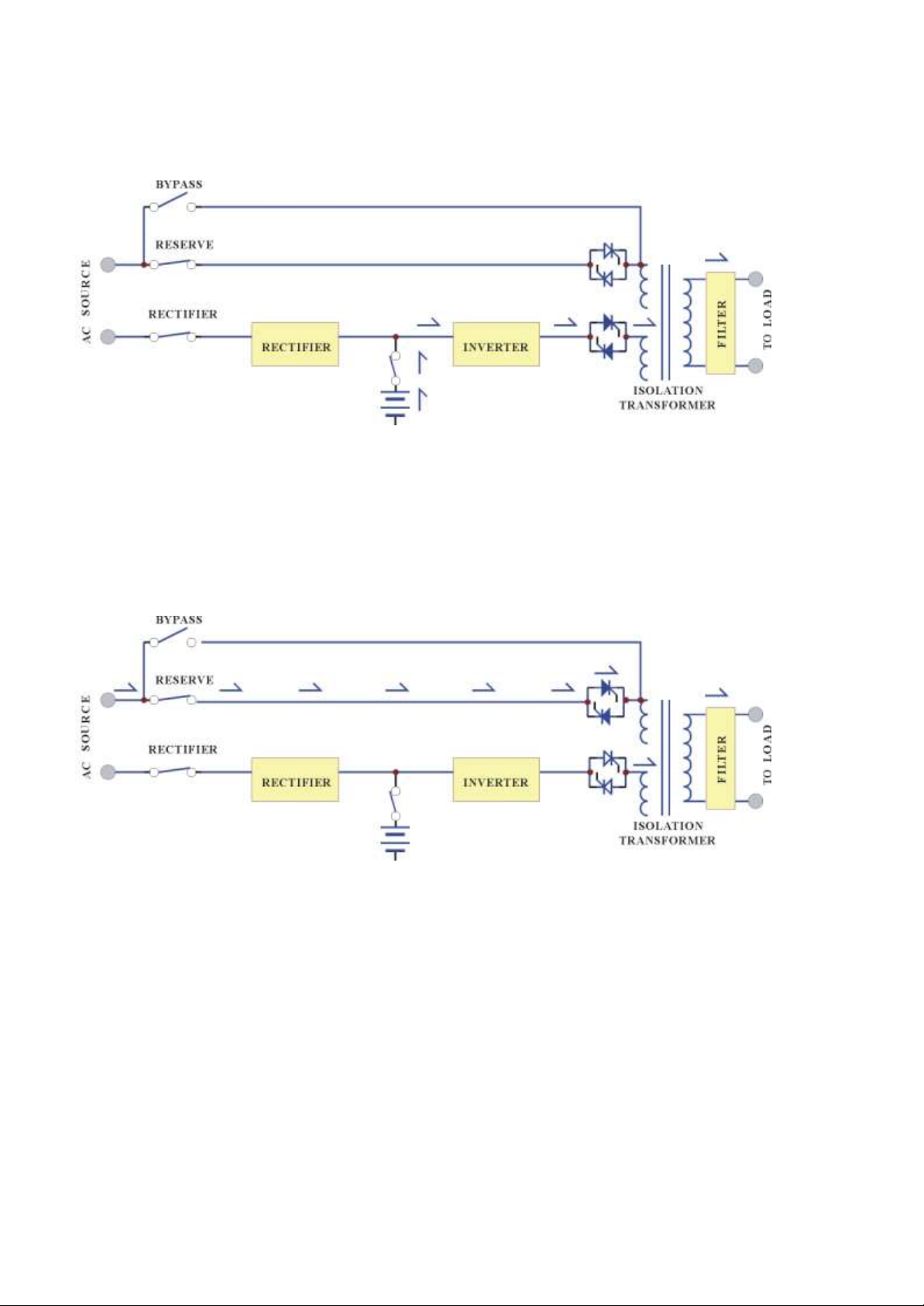
Since the batteries are connected directly to the DC bus, when the AC fails, the
batteries change immediately from receiver to donor, supplying energy to the
inverter instead of receiving energy from the rectifier. The output AC is not
interrupted. Therefore, the load connected to the output is protected.
Reserve Mode:
When the inverter is in an abnormal condition, such as over temperature, short
circuit, abnormal output voltage or overloaded for a period exceeding the
inverter’s limit, the inverter will automatically shut down in order to protect
itself from damage. If the utility power is normal, the static switch shall
transfer the load to the reserve source without interruption of AC output.
Page 15

6005-145 Rev. A 1-4
Maintenance Bypass Mode:
In case of ELI maintenance or battery replacement, and where the load cannot
be interrupted, the user can turn off the inverter, close the bypass breaker and
then open the rectifier and reserve breakers. The AC output will not be
interrupted during manual bypass transfer procedure. Therefore, the
maintenance bypass switch keeps continuously supplying power to the load.
Electricity will not exist in ELI except the output transformer, thus ensuring
the safety of service personnel.
Generally, the ELI is expected to run 24 Hours a day in normal operation mode
once it is installed, except when the utility power fails, under overload
conditions, or during maintenance.
Normal operation with batteries connected provides clean, stable, regulated and
uninterrupted power to the load, free from any spikes and surges. Therefore,
the ELI can be regarded as a perfect AC power source, limited in back-up time,
under mains failure, only by the capacity of the batteries.
Green Mode:
Hybrid design allows customer to select this operation mode for higher
efficiency (fast transfer less than 2ms).
Page 16

6005-145 Rev. A 1-5
1.2. Features and Advantages
(a) Reliable input protection: Circuit breakers are placed in each individual
input loop to ensure power can continue through another loop in case of
breaker trip caused by an abnormal condition in either rectifier or load.
(b) Input surge protection: An MOV (surge protector) is added at the input,
providing protection to both ELI and the load from any lightning surges,
or surges caused by neighboring large loads.
(c) EMI suppression: An EMI filter is added to meet the international EMC
limits. Therefore, very low noise is emitted, and no interference is
supplied to other equipment connected to the same AC source.
(d) Ruggedness: The rectifier employs phase control technology to regulate
the DC bus voltage. This is the most efficient method to charge the
batteries. The SCR used are inherently rugged. Additionally, a large
inductor is added at the input to avoid deforming the AC source
waveform.
(e) High frequency design: The inverter uses high frequency, high efficiency
IGBT, PWM methodology to convert the DC power to AC power.
Therefore, the number of components is fewer, reliability is improved, and
the size and weight of ELI is reduced, performance is improved, and
acoustic noise is minimized.
(f) True Galvanic isolation: An isolation transformer is placed at the output.
This can solve the problem of poor input grounding, can allow a different
ground between input and output, can avoid the annoying problem of
ground leakage current, and can be tied to any potential provided on site.
The AC output is isolated under every mode of operation. Additionally, the
user gets the bonus of attenuation of common mode noise from the output
isolation transformer.
Page 17

6005-145 Rev. A 1-6
(g) Plug & Play Modular design: The power circuit is separated into several
modules plugged into slots in the ELI, which are easy to pull out,
permitting quick maintenance and easier trouble shooting.
(h) Cold start function: the ELI can be started without an AC source, that is,
can be started with battery power only. This is possible because current
limit circuitry is added, preventing the problem of large inrush current
blowing the battery fuse and damaging the DC capacitors when batteries
are connected to an empty DC bus (before the DC bus is energized).
(i) Multi-CPU design: Several CPUs are employed in the control circuit, and
critical functions are designed with parallel redundancy to improve
reliability. Therefore, in case of one CPU failure, the other CPUs keep the
ELI operational, and the output AC is not affected.
(j) Protection against misuse: The ELI is designed with breaker on/off
sensor, power supply sensor, etc. Therefore, any operational mistake made
by the user causes no harm to the ELI.
(k) Accepts wide input range: The ELI is designed to accept a wide input
range, so that it can work effectively under an unstable AC source. All of
the input components used are specifically selected to handle extreme high
voltage and high current.
(l) Operating environment: Each component of the ELI is chosen with large
safety margin to accommodate extreme environments, such as
temperature, humidity, altitude, shock or contamination.
(m) Intelligent charger: The ELI will automatically recharge (boost charge)
the batteries every time the batteries are depleted to a voltage level equal
to 2V/Cell. Thus, the batteries can be restored to full capacity as soon as
possible, and made ready for the next back-up requirement. In order to
keep the batteries in the best condition, the ELI will boost charge the
batteries for several hours (selectable) automatically every month. To
avoid over charging the batteries, boost charge will stop when the ambient
temperature is over 35oC (95oF).
Page 18

6005-145 Rev. A 1-7
(n) Intelligent battery test: The batteries are tested after every boost
(initiated by battery discharge or by the monthly boost charge cycle). This
is done without interrupting the operation of the rectifier, preventing the
risk of output AC failure in case of a bad battery. The user is informed of
the battery condition, so that action can be taken before the full capacity of
the batteries is needed.
(o) Huge charging power: The charging power is selectable (Lo/Me/Hi)
according to Ah rating of the batteries, and can charge up battery banks
providing more than 8Hrs back-up time without adding an extra charger.
(p) MTBF of fans are extended: Fans used to cool the ELI, are designed to
slow down under light load, so that the life expectancy of the fans is
extended beyond the normal.
(q) Redundant power supply: A supplemental power supply is added to
provide redundancy for supplying power to the static switch, so that there
will be AC output no matter what happens to the ELI.
(r) Variety of accessory (options): With built-in intelligent communication
interface as well as output ports of RS-232, RS-485, and dry contacts,
there are several options are hence available such as remote control panel,
3 phases software for PC monitoring, auto dialing module, battery
monitoring module, 3 phases SNMP card.
Page 19
6005-145 Rev. A 1-8
6-PULSE FULL CONTROL RECTIFIER
INPUT
RECTIFIER
BREAKER INDUCTOR
CAPACITOR
SCR
AC
OUTPUT
DC
1.3. Rectifier
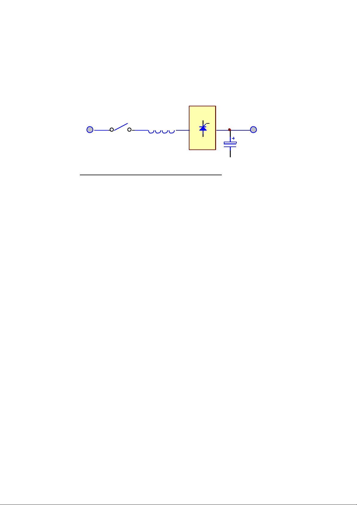
The main function of a rectifier is to convert the AC input to DC power, and
supply it to the inverter. The inverter then converts the DC power to AC power
for the load. The ELI use the DC power to charge the batteries as well, which is
the most efficient method of charging.
ELIs in the sizes 10KVA to 100KVA use 6-pulse fully controlled rectification
(optional 12-pulse). An inductor is added before the rectifier to improve the
power factor, smooth the current waveform and eliminate the harmonic current.
The control circuit regulates the DC bus within 1%. Soft walk-in circuitry
(approximately 20sec.) and current limit circuitry is used to prevent over current
or instantaneous surge current.
Extra under-voltage and over-voltage protections are added to improve
reliability and to shutdown the rectifier in case of abnormal conditions. The DC
bus is adjustable to fit different types of batteries. The power component used in
the rectifier is specially selected to handle extreme high voltage and high
current. The rectifier is designed to operate under a wide range of AC input,
from 177 to 300VAC, to operate under the poor power conditions found in some
areas.
Page 20
6005-145 Rev. A 1-9
12-PULSE FULL CONTROL RECTIFIER
INPUT
RECTIFIER
BREAKER INDUCTOR
CAPACITOR
SCR
AC
OUTPUT
DC
SCR
PHASE SHIFT
TRANSFORMER
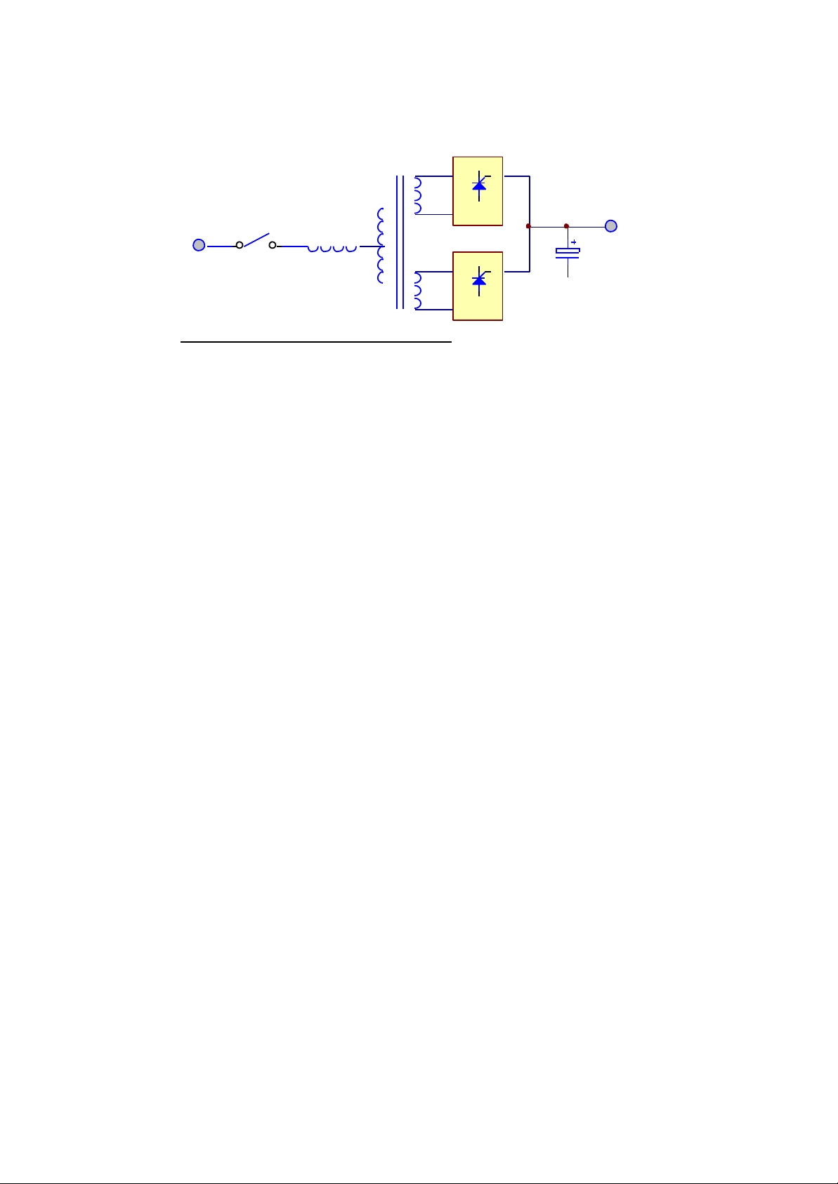
In order to further improve the power factor and reduce harmonic current drawn
by the rectifier, ELI at 120KVA and above, use the 12-pulse full controlled
rectifier. The total current harmonic current can be reduced to around 15%, and
power factor improved to over 0.8. A phase shift transformer is added to achieve
this performance. The input inductor is retained also to obtain the best result.
Although this results in higher cost, the unit is much more reliable and rugged.
Users do not need to increase the input breaker and cable sizes, since input KVA
and harmonic current drawn is minimized, fulfilling the worldwide energy
saving requirements.
The harmonic current can be further lowered by adding harmonic filters (factory
installation available). The total harmonic current can be reduced to
approximately 9%.
Another alternative method to reduce the harmonic current (especially for very
large KVA unit) is to employ 18-pulse full controlled rectifier (available as an
option). The total harmonic current can be reduced to approximately 7%.
Page 21
6005-145 Rev. A 1-10
DC+
DC-
AC
AC
IGBT INVERTER
1.4. Inverter
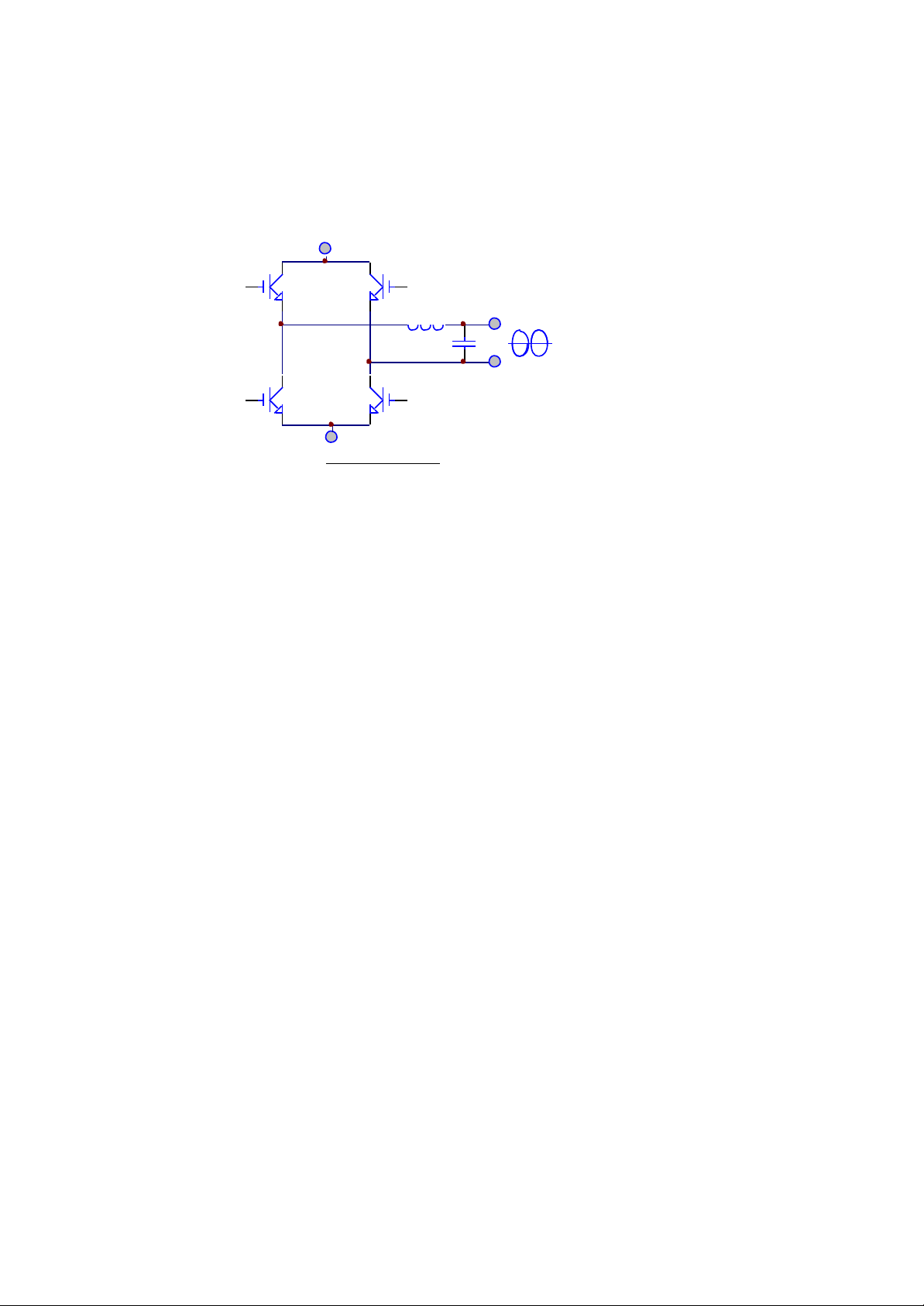
The inverter is composed of IGBT, inductor, capacitor, snubber, control circuitry
and protection circuitry. The inverter converts the DC power from the DC bus to
AC power to supply the output load. The ELI uses IGBT technology which
switches at frequencies beyond the audible range, therefore producing no
audible noise.
The ELI uses voltage regulation circuitry to limit the voltage variation within
1%. Special compensation circuitry is added to eliminate the output distortion.
Every component is oversized to accept the wide DC input range (from 285 to
420VDC), so that the output waveform remains sinusoidal throughout the range.
With the aid of dynamic feedback loop the inverter will keep a sine waveform
even under non-linear load.
An independent inverter is used for each phase. Although it is more expensive,
each inverter has its independent feedback, so that the voltage is unaffected
when load is added to the adjacent phase, producing excellent voltage regulation
under 100% unbalanced load.
The IGBT is operated in its optimal condition to obtain best efficiency, so as to
minimize the power cost of the user.
Page 22
6005-145 Rev. A 1-11
FILT E R
TO L O A D
RESERVE
FILT E R
TO L O A D
INVERTER
RESERVE
INVERTER
RESERVE MODE INVERTER MODE
Usually, the most frequent failures of the ELI occur at the inverter. Therefore,
we have added redundant protection circuitry to protect the inverter. A strong
snubber is added to suppress the spikes and noise, oversized, high quality
components are used throughout, semi-conductor fuses are provided, and
ventilation is maximized. The result of this design is a more rugged, reliable and
high efficient inverter. At the same time, the inverter can sustain overload and
high peak current drawn by the load. Additionally, a longer MTBF is achieved.
1.5. Static Switch
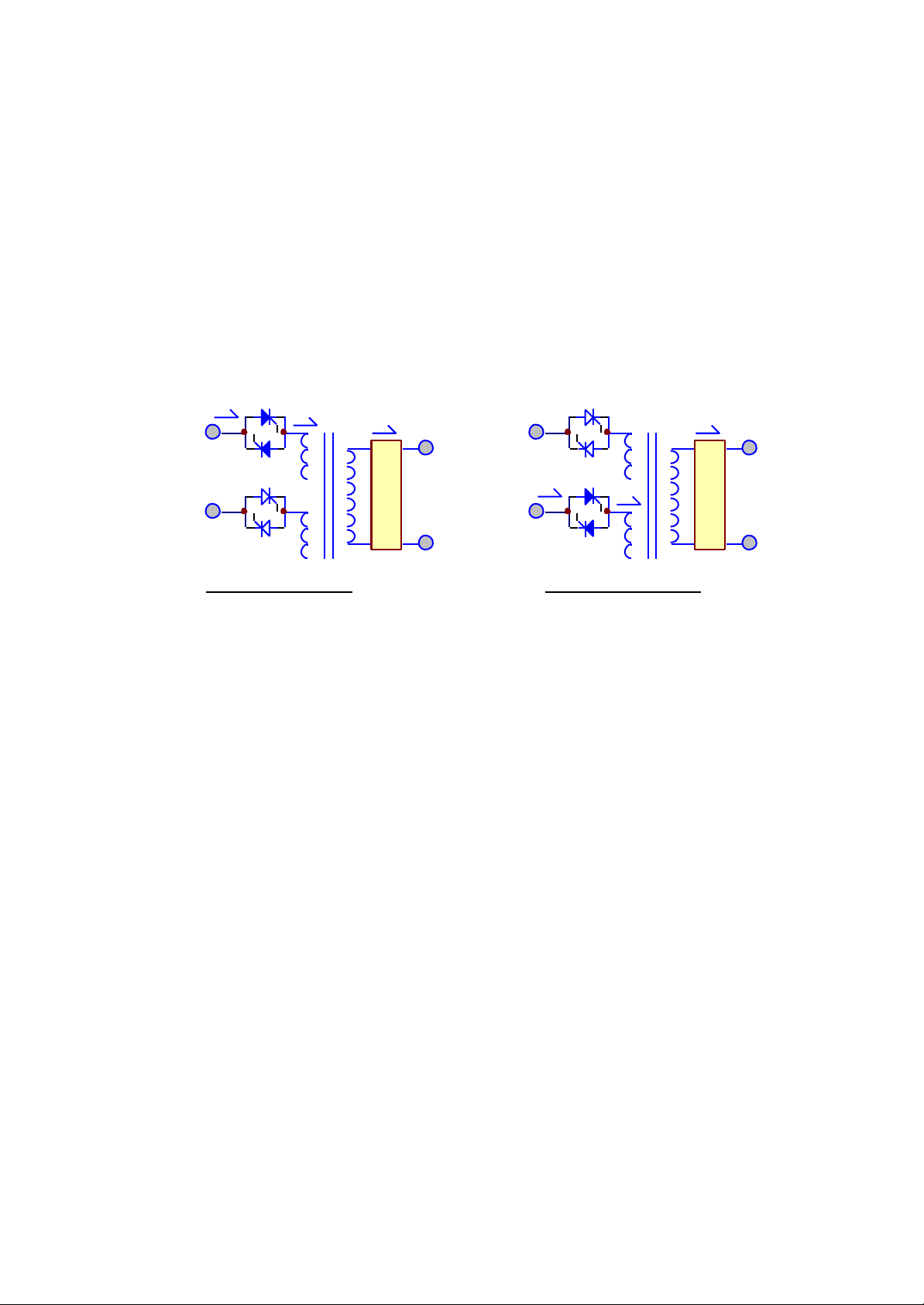
The static switch is composed of two pairs of SCRs, connected back-to-back.
The switch can transfer the load from reserve to inverter or from inverter to
reserve without losing power at the output. Therefore, it is a very important
portion of a ELI.
Detection circuitry is added to the control circuit to achieve zero dead time
transfer. Extra detection logic is employed to control when the static switch
should transfer. For example, when output is short circuited, under normal mode
operation, the ELI detects the short circuit and stops the inverter. The static
switch will not transfer power to the reserve circuit, which might damage the
reserve breaker. In case of an overload, the ELI will stop the inverter after a
period the inverter can endure, and then transfer the load to the reserve circuit,
since the overload capability of the static switch is higher than the inverter.
The transfer action is determined according to the reserve-input voltage and
frequency to protect supplying incorrect power to the load. Finally, there is a
double check by the CPU as to whether the transfer is successful or not.
Page 23

6005-145 Rev. A 1-12
1.6. Maintenance Bypass
Unlike other ELI, the maintenance bypass switch is already installed inside the
ELI for convenience. It should be open under normal operation, and only closed
during maintenance. For the sake of safety of maintenance personnel, all power
supplies inside the ELI should be disconnected before touching any parts inside
the ELI. Thus, the maintenance bypass switch is a necessity to maintain AC
power at the output and yet keep maintenance personnel safe at the same time. If
the bypass breaker is closed under normal operation, the inverter will stop and
the load will be automatically transferred to reserve to prevent the inverter
connecting directly to the AC source. Of course, you cannot switch on the
inverter as long as the maintenance bypass breaker is closed.
To properly use the maintenance bypass breaker, switch off the inverter first.
The static switch will automatically transfer the load to reserve without dead
time. Then one can close the maintenance bypass breaker, then open the reserve
breaker, so that the load gets power from the output without interruption.
1.7. Main Input Circuit Breaker
The main input circuit breaker provides the unit with incoming power
isolation as a well as means of disconnect and input over current
protection.
1.8. Main Output Circuit Breaker
1.9. Battery Circuit Breaker
1.10. Battery
The battery bank; Provides the reserve energy to sustain the load when
suitable AC input power is not present. The batteries are designed and
tested to meet UL 924 requirements. The standard VRLA (Valve
Regulated Lead Acid) batteries are sealed and maintenance-free.
Page 24
6005-145 Rev. A 1-13
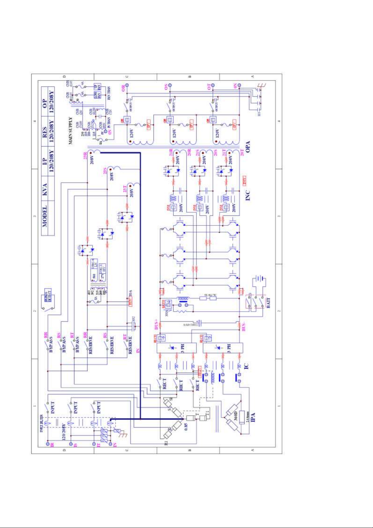
1.11. SINGLE LINE DIAGRAM – (120/208Y)
Page 25
6005-145 Rev. A 1-14
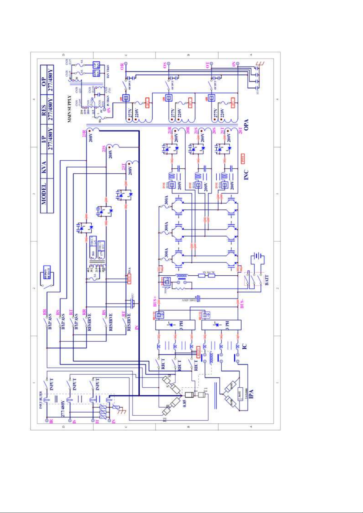
1.12. SINGLE LINE DIAGRAM – (277/480Y)
Page 26
6005-145 Rev. A 1-15
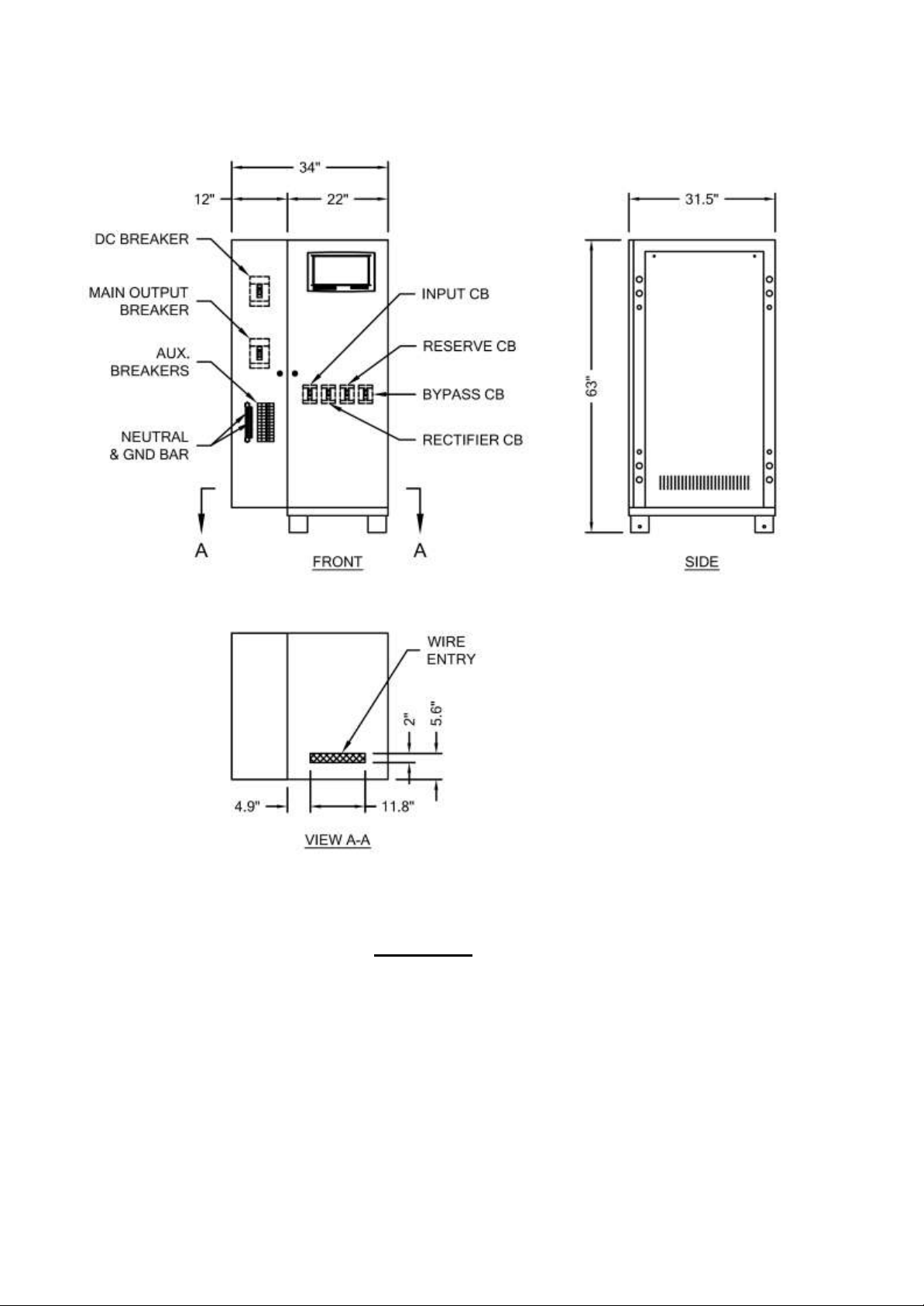
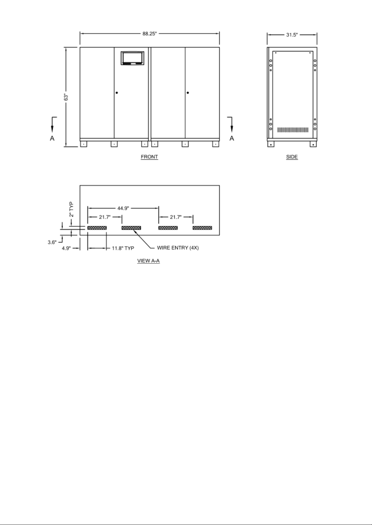
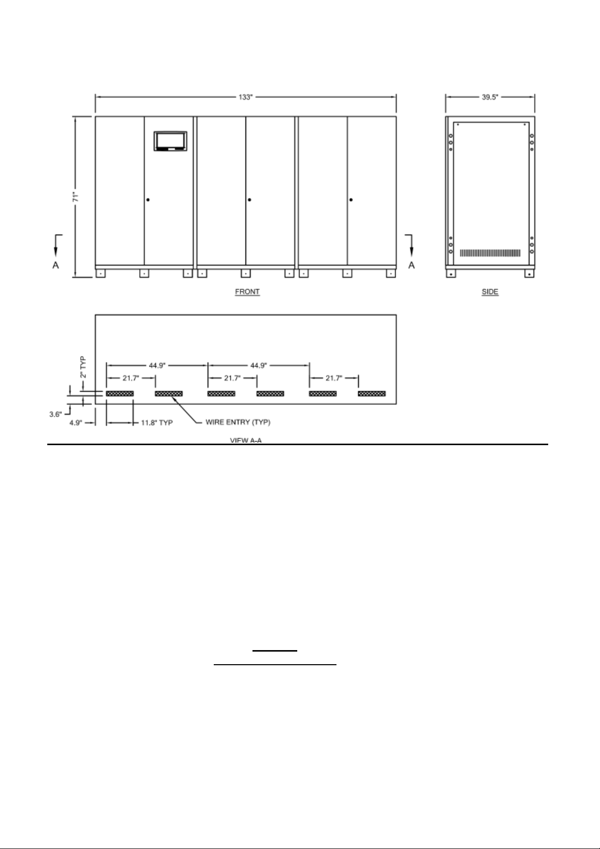
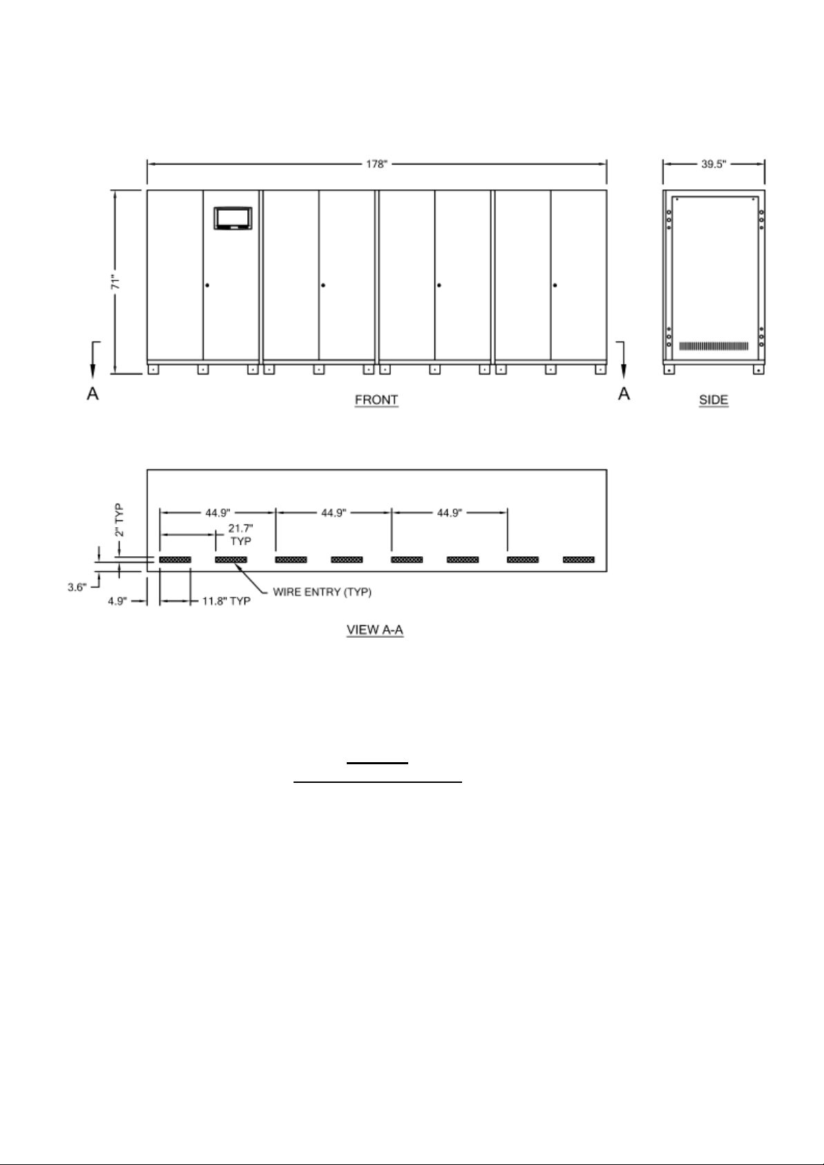
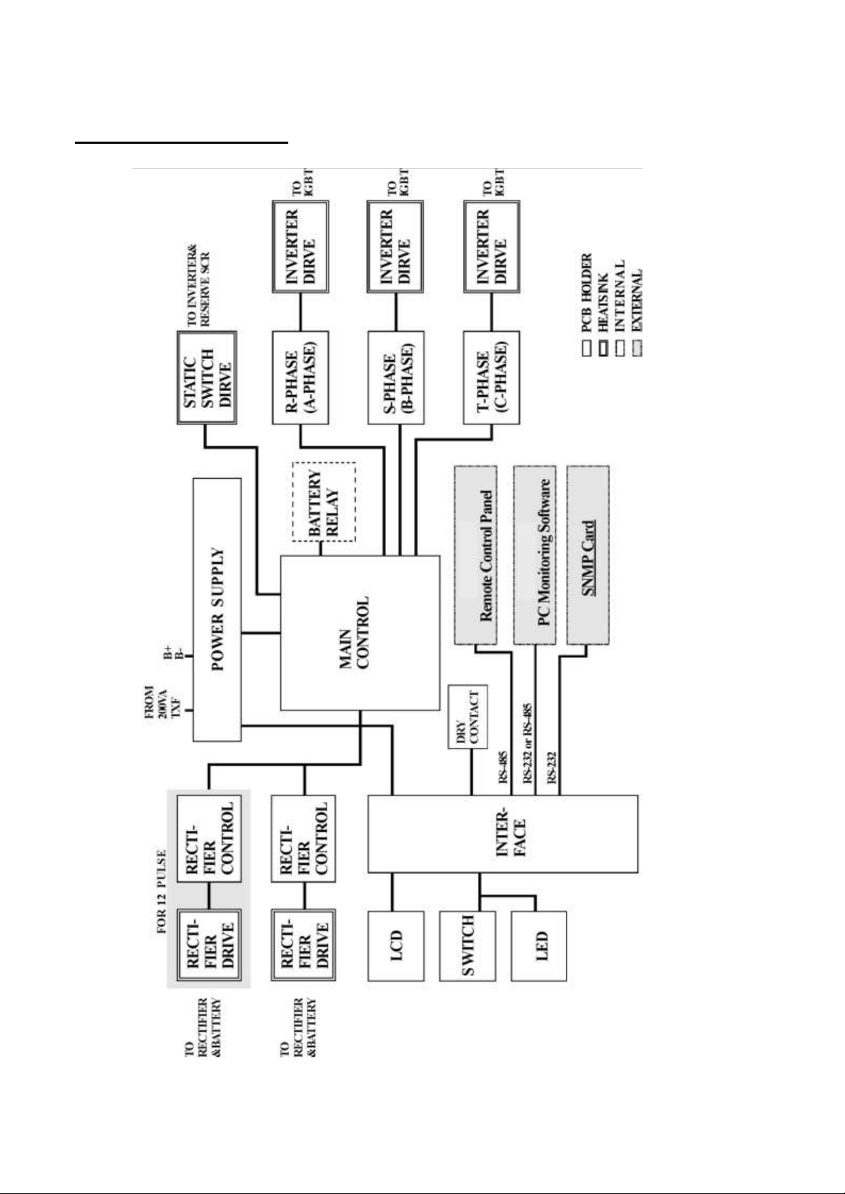
1.13 Dimension & Drawings (electronic cabinet, off white), for
battery cabinet refer to section
CABINET
10KVA - 60KVA
OUTLINE DRAWING
Page 27
6005-145 Rev. A 1-16
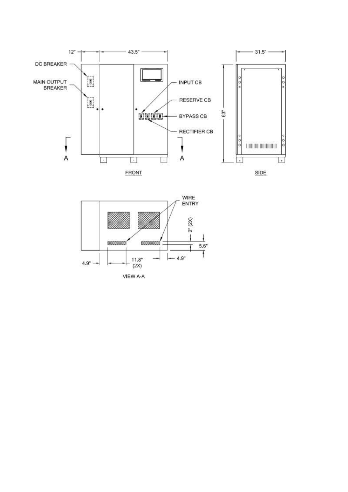
80KVA - 160KVA
OUTLINE DRAWING
Page 28
6005-145 Rev. A 1-17
200KVA - 320KVA
OUTLINE DRAWING
Page 29
6005-145 Rev. A 1-18
400KVA
OUTLINE DRAWING
Page 30
6005-145 Rev. A 1-19
500KVA
OUTLINE DRAWING
Page 31
6005-145 Rev. A 1-20
INTER-PCB DIAGRAM
Page 32
6005-145 Rev. A 1-21
~
~
INVERTER
~
ENTER
TRUE GALVANIC ISOLATED UPS
DATA LINE
EMERGENT
STOP
BATTERY
TEST
150
% LOAD
125
% LOAD
110
% LOAD
~
~
/
~
~
/
LCD
UP
DOWN
ON
OFF
BOOST
CHARGE
HIGH DC
RECTIFIER
SHUTDOWN
ROTATION
ERROR
RECT AC FAIL
BATTERY LOW
SHUTDOWN
BATTERY LOW
RESERVE
FREQ FAIL
RESERVE
AC FAIL
FUSE/OVER
TEMP SD
70
% LOAD
OVERLOAD
SHUTDOWN
HIGH DC
SHUTDOWN
BYPASS ON
SHUTDOWN
INVERTER FAIL
SHUTDOWN
SHORT CIRCUIT
INVERTER SS
INVERTER ON
~
FUSE / TEMP
OVERLOAD
BAT LOW STOP
FAULT
RESERVE FAIL
RECT AC FAIL
WARNING
BAT LOW
HIGH DC
B
A
C
D
E
F
G
I
J
K
L
M
N
O
P
R
Q
H
~
~
INVERTER
~
ENTER
TRUE GALVANIC ISOLATED UPS
DATA LINE
EMERGENT
STOP
BATTERY
TEST
150
% LOAD
125
% LOAD
110
% LOAD
~
~
/
~
~
/
LCD
UP
DOWN
ON
OFF
BOOST
CHARGE
HIGH DC
RECTIFIER
SHUTDOWN
ROTATION
ERROR
RECT AC FAIL
BATTERY LOW
SHUTDOWN
BATTERY LOW
RESERVE
FREQ FAIL
RESERVE
AC FAIL
FUSE/OVER
TEMP SD
70
% LOAD
OVERLOAD
SHUTDOWN
HIGH DC
SHUTDOWN
BYPASS ON
SHUTDOWN
INVERTER FAIL
SHUTDOWN
SHORT CIRCUIT
INVERTER SS
INVERTER ON
~
FUSE / TEMP
OVERLOAD
BAT LOW STOP
FAULT
RESERVE FAIL
RECT AC FAIL
WARNING
BAT LOW
HIGH DC
B
A
C
D
E
F
G
I
J
K
L
M
N
O
P
R
Q
H
1.14 Front Panel
Page 33

6005-145 Rev. A 1-22
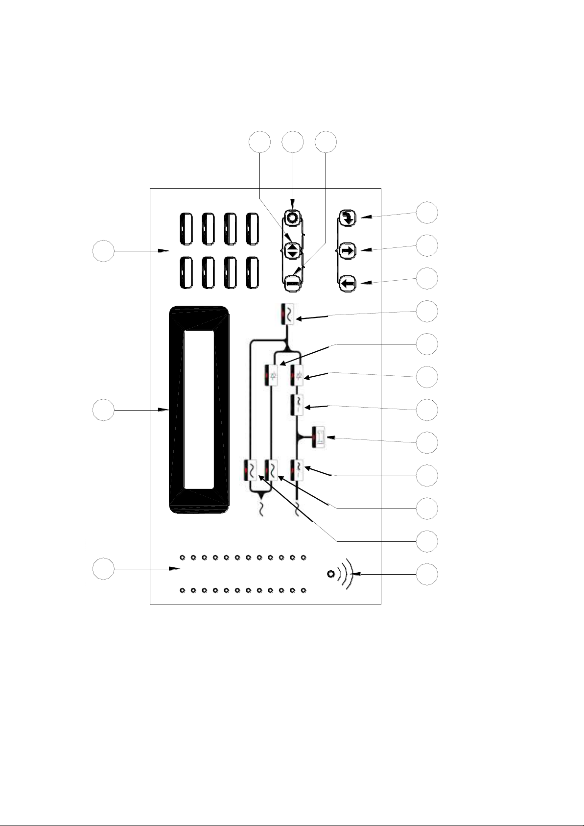
The front panel is located at the front of the PCB holder. It gathers the real time
information of the ELI and shows them clearly to the user. It also provides
switches for controlling and setting the ELI. Through this panel, the ELI can be
not only a stand alone machine supplying the load, but also closely monitored
by the user. Each part of the panel is explained below.
A: LCD display: Real time status, data or historical events are displayed on the
LCD. The ELI parameters, real time clock, inverter, and buzzer also can be
set through this LCD. The LCD is back-lighted by LEDs to provide a sharp
display. In order to lengthen the LED’s life time, the LED are automatically
shut off 3 minutes after no key is activated, but will light up again when one
of the up/down/enter key is pushed.
B: Status LEDs: 24 LEDs, representing all of the important information of the
ELI, provide the most up to date information to the user. Therefore these
LEDs are especially important when abnormal conditions occur. The 24
information items are as shown below:
INVERTER ON – inverter is running.
INVERTER SS – inverter static switch conducts while the reserve static
switch is opened.
SHORT CIRCUIT – ELI output is in short circuit state.
FUSE/OVER TEMP SD – inverter shutdown due to either fuse broken
or over temperature condition.
INVERTER FAIL SHUTDOWN – inverter shutdown due to inverter
output voltage too low.
BYPASS ON SHUTDOWN – inverter shutdown due to bypass breaker
being closed while the inverter is running.
HIGH DC SHUTDOWN – inverter shutdown due to overly high DC
bus voltage condition while the inverter is running.
OVERLOAD SHUTDOWN – inverter shutdown due to overload of the
inverter for a period over that which the inverter can endure; will
restart 7 seconds after overload removed.
70% LOAD – load connected to the output is at or over 70% of the ELI
rating.
Page 34

6005-145 Rev. A 1-23
110% LOAD – load connected to the output is over 110% of the ELI
rating.
125% LOAD – load connected to the output is over 125% of the ELI
rating.
150% LOAD – load connected to the output is over 150% of the ELI
rating.
RESERVE AC FAIL – reserve AC magnitude is out of range.
RESERVE FREQ FAIL – reserve frequency is out of range.
BATTERY LOW – DC bus (or battery) is lower than 320VDC, low
battery shutdown is approaching.
BATTERY LOW SHUTDOWN – inverter shutdown due to DC bus (or
battery) lower than 295VDC (lower than the acceptable DC voltage
of the inverter).
RECT AC FAIL – rectifier AC magnitude is out of range.
ROTATION ERROR – rectifier AC phase rotation is incorrect.
RECTIFIER SHUTDOWN – rectifier shutdown due to DC bus too high
(over 445VDC), will automatically restart 30 seconds after abnormal
situation has been cleared.
HIGH DC – DC voltage over 430VDC and the bus voltage will be
limited at this voltage.
BOOST CHARGE – the batteries are being boost charged by the
rectifier.
BATTERY TEST – batteries are being tested.
EMERGENCY STOP – inverter shutdown due to emergency stop
switch pushed.
DATA LINE – blinks when data is transmitted to or received from the
communication port.
C: Warning LEDs: When abnormal condition happens, these LEDs will light
to warn the user according to the cause of the faulty condition. Therefore all
these LEDs should be extinguished under normal condition. These LEDs are
as shown below:
RECT AC FAIL – rectifier AC input is abnormal either due to AC
magnitude out of the range or phase rotation error, rectifier
shutdown.
RESERVE FAIL – reserve AC input is abnormal either due to AC
magnitude out of range or frequency out of range.
Page 35

6005-145 Rev. A 1-24
FUSE/TEMP –Inverter fuse is blown or over temperature condition
exists.
OVERLOAD – output is overloaded by over 110%, 125% or 150%.
HIGH DC – the LED will light as long as the DC voltage is over
430VDC.
BAT LOW – the LED will light as long as the DC voltage is lower than
320VDC.
BAT LOW STOP – the LED will light as long as the DC voltage is lower
than 295VDC, inverter cannot start.
FAULT – the inverter is shutdown due to abnormal conditions such as
overload, short circuit, high DC, fuse over temperature, bypass
breaker on or emergency stop.
Since these LEDs are located behind the transparent window, the user can
see them clearly without opening the door.
D: Audible (buzzer) alarm: The user should not be expected to watch the ELI
all the time. Therefore, when abnormal conditions occur, an audible sound
should be emitted to warn the user to check the status of the ELI. The alarm
buzzer will beep under any one of the following conditions:
INVERTER IS OVERLOADED-
>110%, beep once / 3 seconds
>125%, beep once / second
>150%, beep twice / second
BACK- UP
>320VDC, beep once / 3 seconds
<320VDC, beep twice / second
<295VDC, no beeping
INVERTER IS SHORT CIRCUITED - beep continuously
FUSE BROKEN - beep continuously
HEAT SINK OVER TEMPERATURE - beep continuously
HIGH DC SHUTDOWN - beep continuously
BYPASS ON STOP - beep continuously
EMERGENCY STOP – (emergency power off) beep continuously
The buzzer will also beep once every time the inverter is switched on or
off to acknowledge to the user that his key is valid and accepted.
Page 36

6005-145 Rev. A 1-25
E. Bypass LED: This LED will light when the maintenance bypass breaker is
closed. When the maintenance bypass breaker is closed, the inverter cannot
be switched on and will stop immediately even when inverter is already
running.
F. Reserve LED: This LED will light when the reserve breaker is closed, and
there is AC power supply present at the reserve terminal.
G. Rectifier LED: This LED will light when the rectifier is operating normally,
meaning the rectifier Mains are within the range specified, the rotation
sequence of three phases is correct, the rectifier breaker is closed, and no
high DC voltage is on the bus.
H. Back-up LED: This LED will light when the ELI is in back-up mode. This
is also as the indicator for battery test result. If the battery test does not pass,
this LED will flash even if the ELI is not in back-up mode, to prompt the
user to change the batteries.
I. Inverter LED: This LED will light when the inverter is switched on,
indicating whether the inverter is running or not.
J. Inverter SS LED: This LED will light when the inverter static switch is
turned on and the reserve static switch is turned off, i.e., the load is supplied
from the inverter. Usually this LED will light 7 seconds after the inverter is
switched on.
K. Reserve SS LED: This LED will light when the reserve static switch is
turned on and the inverter static switch is turned off, i.e., the load is supplied
from the reserve. Since the reserve static switch and inverter static switch
will never both turn on simultaneously, the Inverter SS LED and the Reserve
SS LED should never both be lit simultaneously.
L. Output LED: This LED will light when there is AC power present at the
output terminal. This is an important indication to the user at to whether AC
is available at the output or not.
Page 37

6005-145 Rev. A 1-26
M. Up key: This is a LCD control key. It is for moving the cursor one item
upward when items are being selected or for changing the number/character
forward when data or parameter of the ELI is being set.
N. Down key: This is a LCD control key. It is for moving the cursor one item
downward when items are being selected or for changing the number/
character backward when data or parameter of the ELI is being set.
O. Enter key: This is a LCD control key. It is for changing backward to the
previous page, and also for confirming the number/character /item is
selected.
P. Inverter on switch: This is an inverter control switch. When this key is
pushed with the control key simultaneously, the inverter will be switched on.
Q. Inverter control switch: This is an inverter control switch. When this key is
pushed with the inverter on key simultaneously, the inverter will be switched
on. Similarly, when this key is pushed with the inverter off key
simultaneously, the inverter will be switched off. Thus, this key is a guard
for mistaken key strokes.
R. Inverter off switch: This is an inverter control switch. When this key is
pushed with the control key simultaneously, the inverter will be switched
off.
Page 38
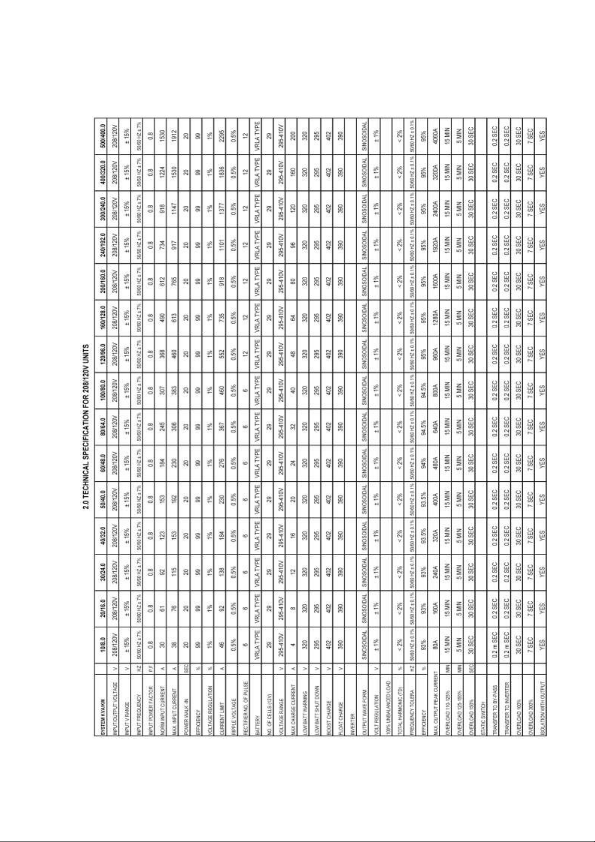
2-1
2 TECHNICAL SPECIFICATION
2.1 For 208/120V Unit.
6005-145 Rev. A
Page 39
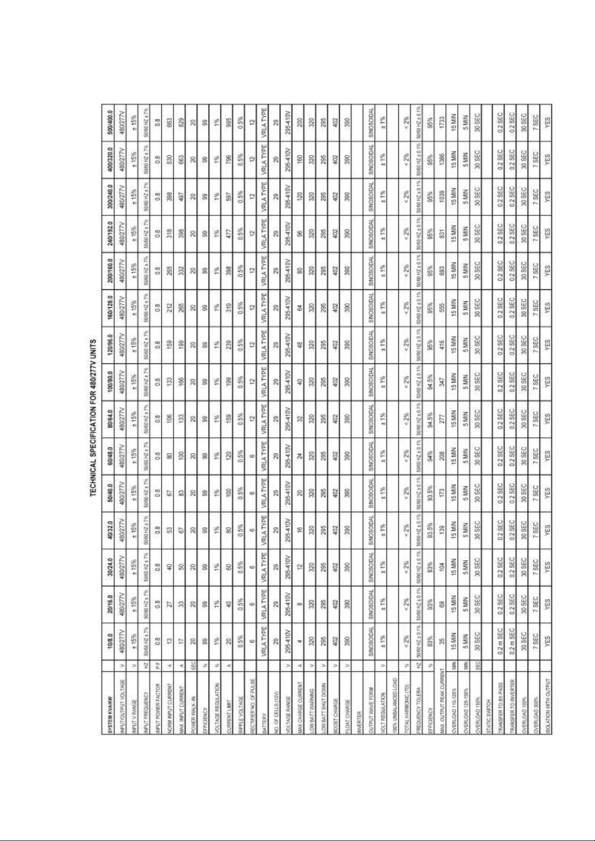
2-2
2.2 For 480/277V Unit.
6005-145 Rev. A
Page 40
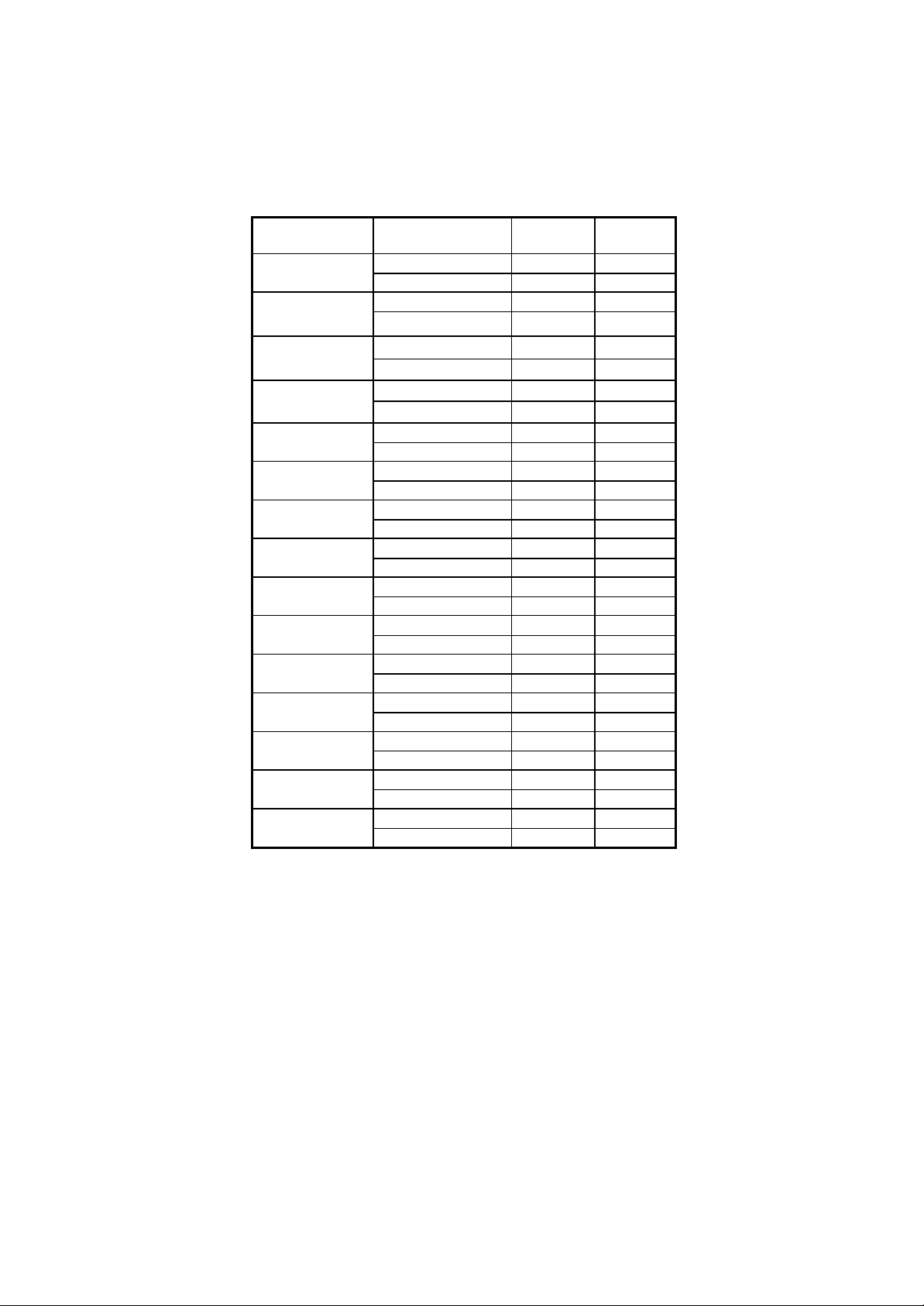
2-3
kVA/kW
MODEL NO.
INPUT
VOLTAGE
OUTPUT
VOLTAGE
10KVA/8KW
PW010B05ATT3
208Y/120
208Y/120
PW010H09ATT3
480Y/277
480Y/277
20KVA/16KW
PW020B05ATT3
208Y/120
208Y/120
PW020H09ATT3
480Y/277
480Y/277
30KVA/24KW
PW030B05ATT3
208Y/120
208Y/120
PW030H09ATT3
480Y/277
480Y/277
40KVA/32 KW
PW040B05ATT3
208Y/120
208Y/120
PW040H09ATT3
480Y/277
480Y/277
50KVA/40KW
PW050B05ATT3
208Y/120
208Y/120
PW050H09ATT3
480Y/277
480Y/277
60KVA/48KW
PW060B05ATT3
208Y/120
208Y/120
PW060H09ATT3
480Y/277
480Y/277
80KVA/64KW
PW080B05ATT3
208Y/120
208Y/120
PW080H09ATT3
480Y/277
480Y/277
100KVA/80KW
PW100B05ATT3
208Y/120
208Y/120
PW100H09ATT3
480Y/277
480Y/277
120KVA/96KW
PW120B05ATT3
208Y/120
208Y/120
PW120H09ATT3
480Y/277
480Y/277
160KVA/128KW
PW160B05ATT3
208Y/120
208Y/120
PW160H09ATT3
480Y/277
480Y/277
*200KVA/160KW
PW200B05ATT3
208Y/120
208Y/120
PW200H09ATT3
480Y/277
480Y/277
*240KVA/192KW
PW240B05ATT3
208Y/120
208Y/120
PW240H09ATT3
480Y/277
480Y/277
*300KVA/240KW
PW300B05ATT3
208Y/120
208Y/120
PW300H09ATT3
480Y/277
480Y/277
*400KVA/320KW
PW400B05ATT3
208Y/120
208Y/120
PW400H09ATT3
480Y/277
480Y/277
*500KVA/400KW
PW500B05ATT3
208Y/120
208Y/120
PW500H09ATT3
480Y/277
480Y/277
2.3 Model number charts
6005-145 Rev. A
*Available upon request only.
Page 41

3-1
3.
INSTALLATION
3.1 Site & Environment Considerations
The main function of the ELI is to provide a safe, clean independent
electrical supply to the sensitive load so that it is free from any random variations,
disturbances or interruptions of the utility mains. The ELI also provides a
constant power which is perfectly regulated in both voltage and frequency. When
the mains are not available, the ELI provides optimal back-up time depending on
the battery bank capacity connected to it.
The life expectancy of the ELI is 10 years and greater. Batteries are not included,
because life expectancy of the batteries depend on the type of battery, the
temperature and humidity of the environment in which it is installed, and the type of
charger that is applied to the battery. Therefore optimal life expectancy of the ELI
can be achieved by careful consideration of the site and environment.
The following precautions and recommendations should be checked in considering
the site and environment of the ELI:
(a) The ELI should be located in a place with adequate ventilation (refer to the
specification of the heat dissipation of the ELI). If the ELI is installed indoors,
care must be taken to insure the evacuation of heat from a closed room will be
exhausted.
(b) Adequate space (at least 1M) should be allowed to open the door, and
unobstructed by other objects for operation or maintenance. Adequate space
(at least 1M) should be allowed at the top of the ELI, to assure heat dissipation
is ventilated through the openings.
(c) Do not put any objects on the top of the ELI that may obstruct ventilation. Do
not locate the ELI near any heat source, machinery which produce metallic
dust or powder, or any facility that will produce corrosive substances or
vapor.
(d) Protect the ELI from accidental damage from fire extinguishing (sprinkler)
systems. Protect the ELI from abnormal conditions with a dedicated cutoff
from the incoming power.
6005-145 Rev. A
Page 42
3-2
(e) It is necessary to guarantee the temperature and humidity values of the site
into which the ELI will be installed. These should be within the range
allowed by the specification. The ELI is capable of continuous normal
operation within a temperature range of 0°(32°) to 40° (104°). For optimal
performance and reliability, and to prolong lifetime, it is recommended to
keep the environment temperature below 25°, and humidity below 80%.
(f) If the ELI is installed outdoors, avoid direct exposure of the ELI to the
sunlight, wind, and rain. Avoid any exposure to sand or dust.
(g) The floor loading capacity should be high enough to endure the weight of the
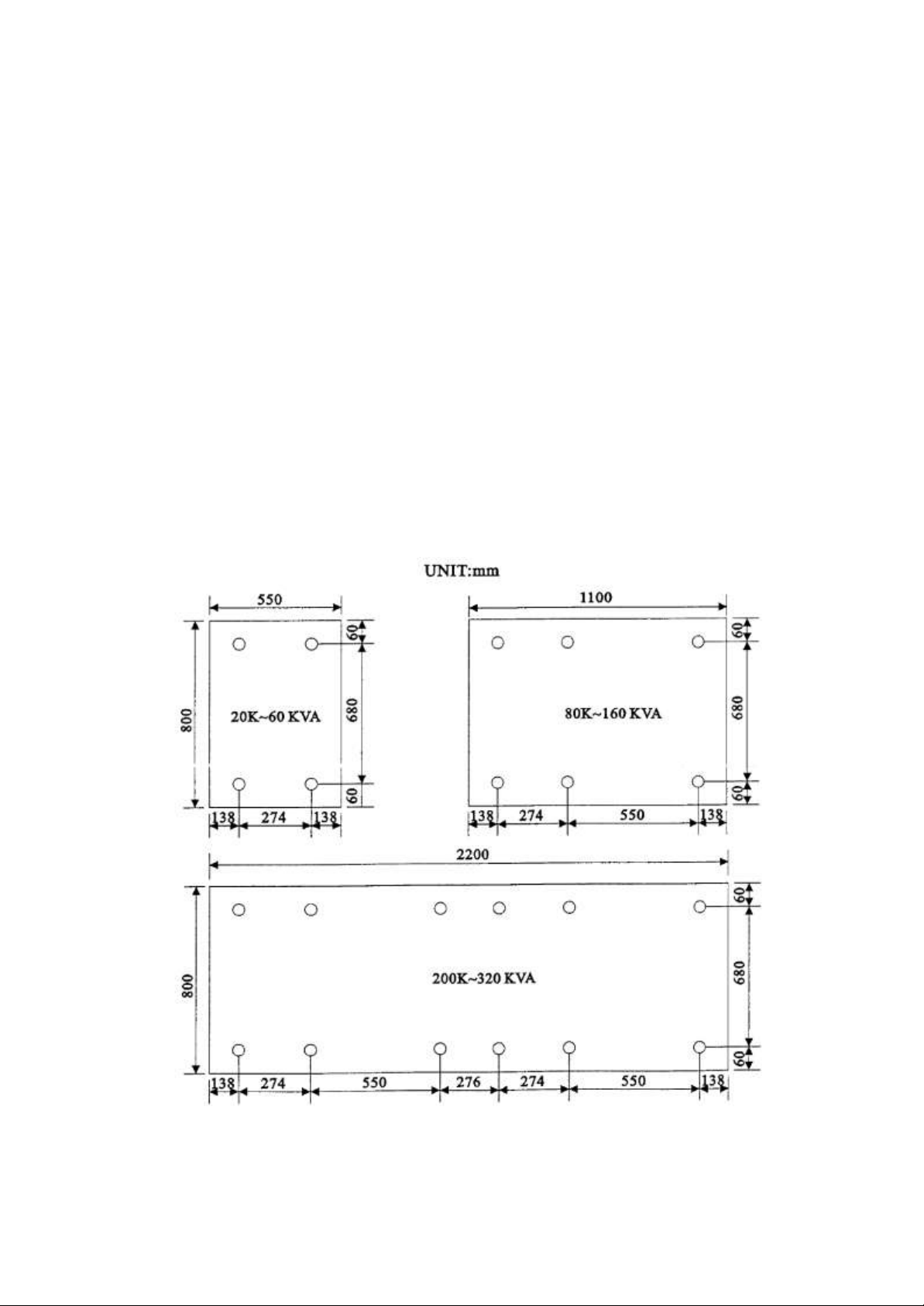
ELI. The ELI is mounted on four right-angled steel angles. Insert
corresponding bolts and nuts (dia. 1/2”) into the floor for securing the ELI
on the floor when it is located in an area where earthquakes is possible, or
where motion may occur, e.g. vehicle mounted. Layout dimensions are shown
below.
6005-145 Rev. A
Page 43

3-3
(h) Walls, ceilings, and floors near the ELI should be preferably constructed of non-
combustible materials. A portable fire extinguisher should be accessible nearby in
case of hazard.
(i) Avoid accumulating combustible materials of any sort in or around the ELI system.
The floor area surrounding the ELI should be kept clean so that foreign materials
are not sucked into the unit, thus causing a short circuit and damage to the system.
(j) Access to the ELI room should be limited to a minimum number of operation and
maintenance personnel only. The doors should be kept locked and the keys should
be confined to authorized personnel only.
(k) Personnel who operate or maintain the ELI system should be proficient in normal
and emergency operational procedures. New personnel should be trained and
qualified prior to operating the equipment.
(l) Although the ELI has passed International EMC tests, it is recommended that the
ELI not be installed near any equipment that is susceptible to electro-magnetic
interference, such as computer systems, monitors, radios, etc.
(m) It is preferable to place the ELI near to the source rather than near to the load.
6005-145 Rev. A
Page 44

3-4
3.2 Unpacking
Carefully unpack the ELI, and then carefully locate the ELI onto the site which has
selected, with all the points in section 3.1 kept in mind.
The ELI has had detailed production and QC testing of all the electrical and mechanical
characteristics prior to shipment from the factory. Therefore, the ELI should be in
proper condition upon receipt. Once received, the ELI should be first checked visually
to determine if any physical damage has occurred during transportation.
Then check to insure that all the accessories/options (match with your purchase order)
have been included.
- DOOR KEY
- THIS INSTRUCTION MANUAL
- BATTERY FUSE (FOR BATTERY CABINET ONLY)
- SPARE SCREWS FOR COVER PLATE
- SPARE SCREWS FOR CONNECTION TERMINALS etc.
Lastly, check to insure that the specification of the ELI is identical to the specification
of your order. The key items in the specification you must check are:
- RATED POWER OF THE ELI,
- INPUT VOLTAGE & FREQUENCY
- OUTPUT VOLTAGE & FREQUENCY
- NO. OF OUTPUT PHASES (1Φ OR 3Φ)
- BATTERY VOLTAGE OR CELL NO.
Also check to insure that the necessary documentation is attached:
- GUARANTEE CARD
- AGENT/SERVICE CENTER INFORMATION
6005-145 Rev. A
Page 45

3-5
3.3. Cable Selection
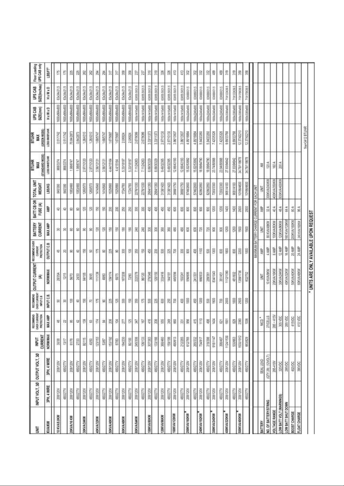
The following tables list typical information concerning the KVA of the ELI versus the
size and rating of the cables. Inadequate cable size or over sized breakers will create
risk of fire or damage of insulation. Therefore, please use the following tables to
determine the input circuit breaker rating and the size of cable for input, output and
battery connections. All rating must comply with local electrical codes.
6005-145 Rev. A
Page 46
3-6
3.4 Input/Output protective device rating and BTU/HR with floor loading chart.
6005-145 Rev. A
Page 47
3-7
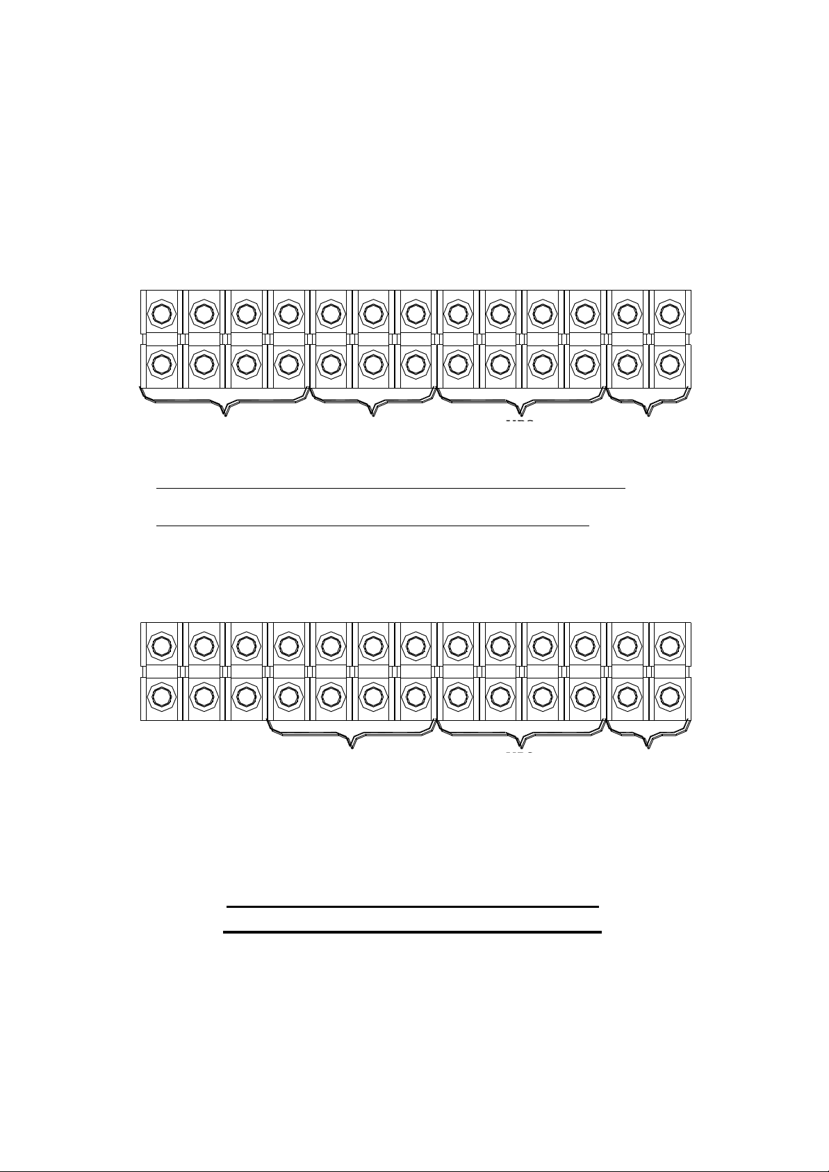
RR RS RT IN IR IS IT OR OS OT ON B+ B-
RESERVE
INPUT
RECTIFIER
INPUT
UPS
OUTPUT INPUT
BATTERY
INPUT
RECTIFIER & RESERVE
IN IR
UPS
OUTPUT
ORITIS OS OT
BATTERY
INPUT
B-ON B+
3 PHASE INPUT / 3 PHASE OUTPUT
TERMINAL WITH TWO SOURCE
ELI
ELI
3.5 Terminal Connection
Although different sizes of ELI may have slightly different cable connection terminal
blocks, all ELI connection terminal alignments falls into one of the following types:
3 PHASE INPUT / 3 PHASE OUTPUT
TERMINAL WITH SINGLE SOURCE
Note: Tree extra terminals are installed for convenience of changing the unit to separate
reserve input.
6005-145 Rev. A
Page 48

4. OPERATIONS
After all cables have been connected, and power source is available at the input
terminals, the ELI is ready to operate. Before turning on any switch or breaker, once
again check the following:
(a) Check that the input voltage conforms to the ELI’s rated input voltage.
(b) Check that the input frequency conforms with the ELI’s rated input
frequency.
(c) Check that the load at the output is switched off.
(d) Check that all breakers and the battery disconnects are opened.
(e) Check that no foreign material is inside the ELI.
4.1. Startup Procedure
To start the ELI from complete shutoff to normal operation, follow the steps below
to turn on the ELI.
(a) In case there is an extra input breaker for some special specification, please close
the input breaker first.
(b) Close the reserve breaker – The reserve and output LED on the mimic panel will
light up, indicating the reserve static switch loop is energized. Therefore the output
has power now. The supply of power in the ELI is established and the fans will
operate.
(c) Close the rectifier breaker - The rectifier will be automatically started if the power
source connected is correct. Wait 30 sec for DC bus voltage to rise until the
warning LEDs of “BAT LOW” and “BAT LOW STOP” go off (on the front
panel). Now, the DC is already ready for the inverter.
(d) Close the (optional) battery breaker - For safety purposes, a breaker (or fuse) is
employed between the batteries and the DC bus. Now the batteries will take over
to supply the DC bus if rectifier mains fail.
6005-145 Rev. A
4-1
Page 49
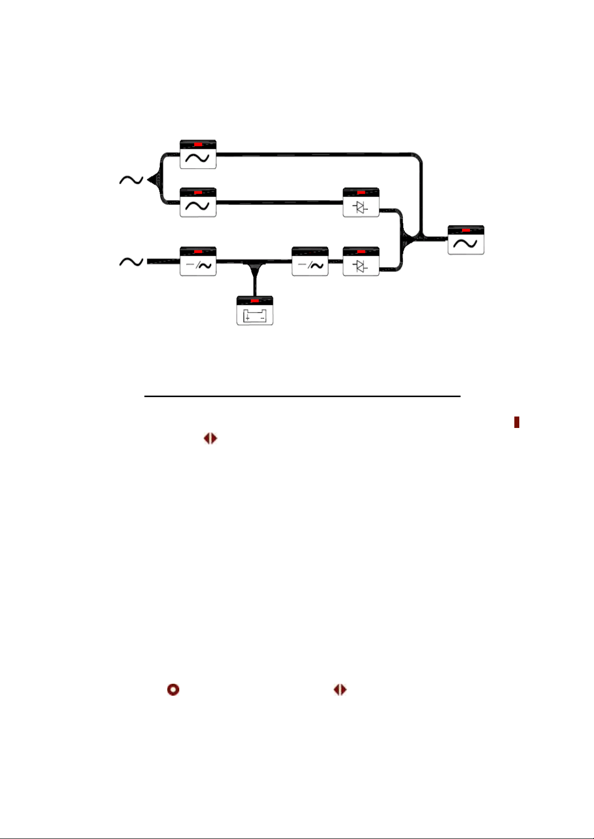
MIMIC DISPLAY UNDER NORMAL OPERATION
(e) Push inverter ON switch – To turn on the inverter, the inverter ON switch ( ) and
the control switch ( ) must be pressed simultaneously. The inverter will start
working and inverter output will be established in 4 seconds. The load will
automatically be transferred to the inverter 3 seconds later. Now the ELI is in
normal operation.
(f) Check if the mimic LED is correct, as shown in the figure, above. All warning
LEDs on the right side are off, two LEDs: ‘INVERTER ON’ and ‘INVERTER SS’
on the left side should be lit. If the load is over 70%, the ‘70% LOAD’ LED will
also be lit.
4.2. Shutdown Procedure
If you want to shutdown the ELI completely (no power at output or inside), please
follow the steps below.
(a) Switch off the inverter – The inverter can be switched off by pressing the inverter
OFF switch ( ) and the control switch ( ) simultaneously. The load will be
automatically transferred to reserve without interruption.
6005-145 Rev. A
4-
2
Page 50

(b) Open the (optional) battery breaker – If you want to shutdown all the power of the
ELI, continue to open the battery breaker. Now the DC bus is only supported by
the rectifier.
(c) Open the rectifier breaker – Opening the rectifier breaker will further take the
power source away from the DC bus, and the DC bus will start to drop slowly.
After 5 minutes, the DC bus will drop to a safe level (< 20VDC).
(d) Open the reserve breaker – Before opening the reserve breaker, power exists at
the output. After opening the reserve breaker, the output (or load) will no longer
have power. Therefore, before opening the reserve breaker, insure there is no
critical load connected to the output.
(e) If there is input breaker, open it accordingly.
(f) At this point, all power has been cut off, and there should none of the LED’s or
LCD’s lit. The ELI now is completely shut off.
4.3. From Inverter to Maintenance Bypass Procedure
If you want to stop the ELI for maintenance and do not stop the power supply from
the load, you can follow the steps below to turn the ELI to maintenance bypass
mode without interrupting the output power supply.
(a) Switch off the inverter – The inverter can be switched off by pressing the inverter
OFF switch ( ) and the control switch ( ) simultaneously. The load will be
automatically transferred to reserve without interruption.
(b) Open the (optional) battery breaker – You have to shutdown the power inside the
ELI. Therefore, continue to open the battery breaker.
6005-145 Rev. A
4-
3
Page 51

(c) Open the rectifier breaker – Opening the rectifier breaker will take the power
source away from the DC bus, causing the DC bus to drop slowly. After 5 min.,
the DC bus will drop to a safe level (<20VDC).
(d) Close the bypass breaker – The reserve breaker and reserve static switch are still
conducting. Therefore, when the maintenance bypass breaker is closed, power
will flow through the bypass loop instead of the reserve loop because of the lower
impedance of bypass loop.
(e) Open the reserve breaker – You can now open the reserve breaker to free the ELI
from any power supply.
4.4. From Maintenance Bypass to Inverter Procedure
If the ELI is in maintenance bypass mode, and you want to turn the ELI to normal
mode without interrupting the output AC, please follow the steps below.
(a) Close the reserve breaker – The reserve and output LED on the mimic will light,
indicating the reserve static switch loop is energized, and the output has power.
The power supply in the ELI is also established, and the fans will operate.
(b) Open the bypass breaker – The inverter cannot be switched on while the
maintenance bypass breaker is closed (because the CPU will sense the breaker
and prevent the inverter from connecting directly to AC source). Since the reserve
breaker is already closed, power goes through the reserve loop if the bypass
breaker is open. Thus, AC at the output will not be interrupted.
(c) Close the rectifier breaker - The rectifier will be automatically started if the power
source connected is correct. Wait 30 sec for DC bus voltage to rise until the
warning LEDs of “BAT LOW” and “BAT LOW STOP” go off (on the front
panel). Now, the DC is already ready for the inverter.
6005-145 Rev. A
4-
4
Page 52
(d) Close the (optional) battery breaker – For safety purposes, a fuse is employed in
the battery to the DC bus. Now the battery will take-over to supply the DC bus if
the rectifier mains fail.
(e) Push inverter ON switch – To turn on the inverter, the inverter ON switch ( ) and
the control switch ( ) must be pressed simultaneously. The inverter will start
working and inverter output will be established in 4 seconds. The load will
automatically be transferred to the inverter 3 seconds later. Now the ELI is in
normal operation.
4.5. Green Mode: customer selectable for green mode (fast transfer less than 2ms).
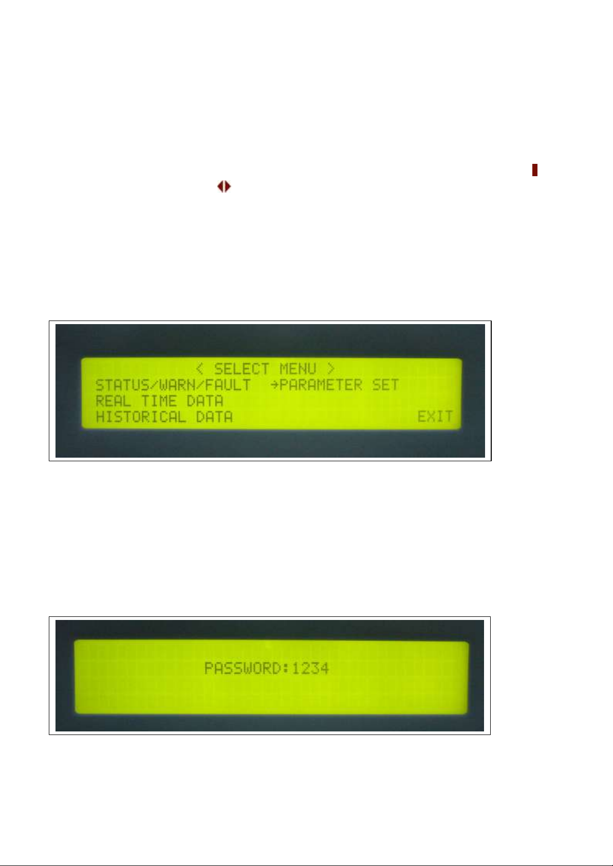
(a) Menu 1 – Select Menu
The Select Menu is for the user to select, via the cursor (→), the type of data the
user wants to view, such as, inverter on/off, buzzer on/off, charging time and
magnitude, date/time etc. The cursor (→) can be moved upward by the UP(↑) key,
and can be moved downward by the DOWN(↓) key. The selection is confirmed by
pressing the ENTER key (←┘), and change to the menu at which the cursor is
pointing. If the item “PARAMETER SET” is selected, the LCD will jump into a
screen which will ask the user to key in the password. See the figure below.
The password is a 4 digit number which can be changed upward or downward by the
6005-145 Rev. A
4-
5
Page 53
UP(↑) or the DOWN(↓) key, and can be confirmed by the ENTER(←┘) key. The
selection will continue if the correct password is entered, or will go back to MENU 0,
the MAIN MENU, if no correct password is entered after 3 trials. The password for
entering the < PARAMETER SET > menu is 1-2-3-4.
The entering of MENU 12, the OTHER SETTING menu, is permitted by another
password, to be used by maintenance personnel. Users can obtain this password from
the manufacturer for user’s maintenance technicians.
If “EXIT” is selected (blinking instead of pointed by cursor), the screen will return
to MENU 0.
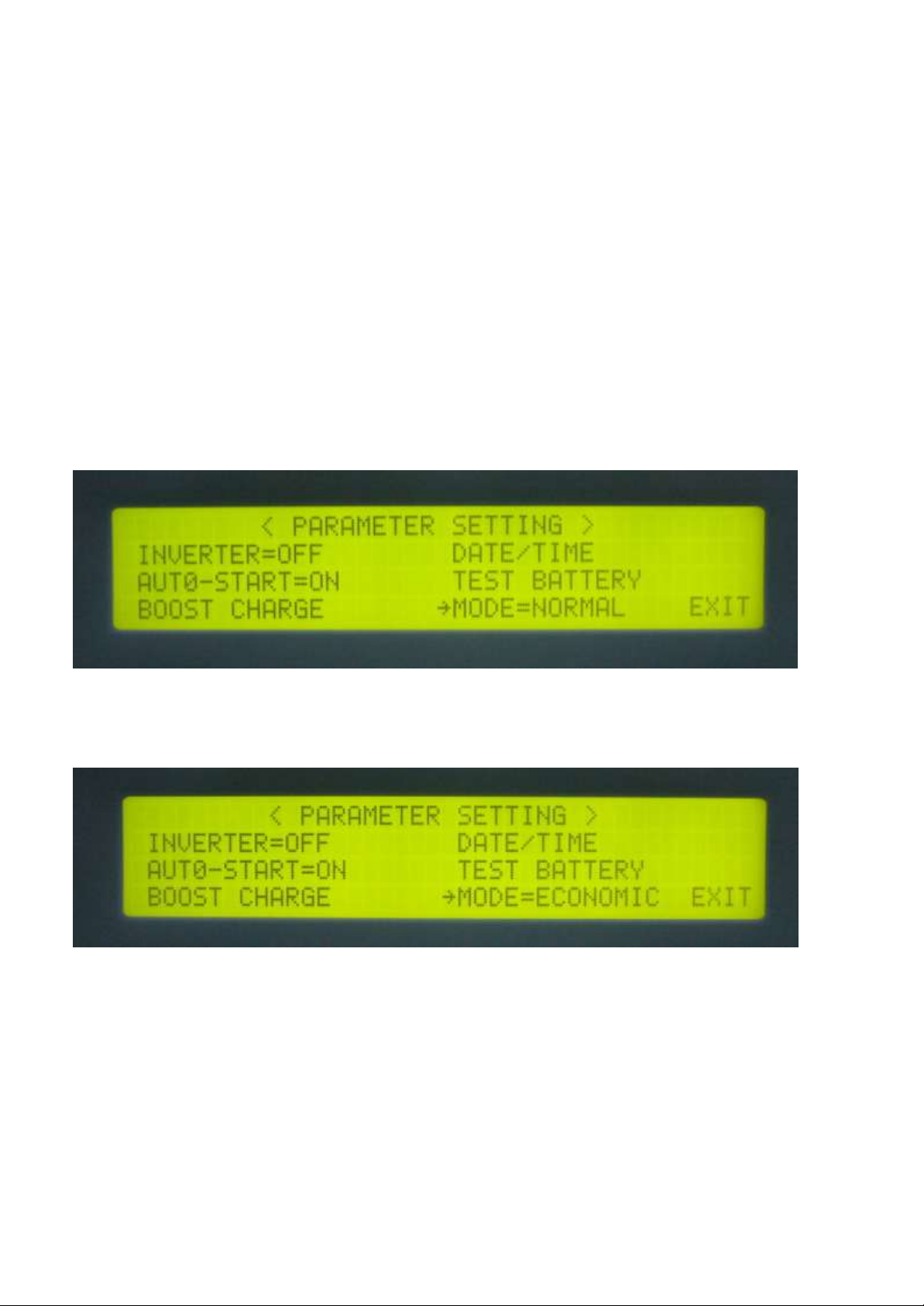
Go to Model Selection Screen
Then, Select the MODE=ECONOMIC.
Note:If you wan to Set the Operating Mode Back to NOMAL MODE, then go to
the Mode Selection Screen, and then Select the MODE=NORMAL.
6005-145 Rev. A
4-
6
Page 54

W E L C O M E T O U S E T H E E
L I
P / N : 5 0 3 3 A
S / N : 1 2 3 4 5 6 7 8 9 0
I D : 0 1
5 0 K V A I : 2 2 0 / 3 8 0 V / 5 0 H Z O : 2 2 0 / 3 8 0 V / 5 0 H Z
2 0 0 2 / 0 2 / 0 1
T U E
0 8 : 0 0 A M
5. LCD DISPLAY
The LCD can display much more information than can the LEDs. In order to make
the display sharp and readable, the LCD is back-lighted by LEDs. But to further
prolong the life of the LEDs, the CPU will cut off power to the LEDs 3 minutes
after the last keystroke of UP, DOWN or ENTER is pressed. The backlighting will
resume if the UP, DOWN or ENTER key is subsequently pressed. Page displays of
the LCD are described below. This screen will refresh once the system power is
enabled (i.e. the default screen).
5.1. Menu 0 – Main Menu
The first row will display the greeting text set by the factory. Changing the text of
this row is not recommended. The parameter no. (P/N), serial number (S/N), and the
identification number (ID) are displayed in the second row. While the third row will
display the KVA rating, input rating and output rating of the ELI. Changing the
parameter number of the second row will also change the rating displayed in the
second row (rating is automatically generated by CPU inside the ELI according to
the P/N number).
WARNING: Never change the parameter number yourself, because some
parameters will be changed accordingly.
6005-145 Rev. A
5-1
Page 55

< S E L E C T M E N U >
→ S T A T U S / W A R N / F A U L T
P A R A M E T E R S E T
R E A L T I M E D A T A
H I S T O R I C A L D A T A
E X I T
P A S S W O R D : 1 2 3 4
Serial number is set by factory for the convenience of maintenance personnel who
may need to refer to the serial number of the ELI serviced. The identification
number is set only when an external control module is connected to more than one
ELI. Each ELI must have a unique number to identify itself, and it should be set by
installation technical personnel after installation. The YEAR/MONTH/DATE, DAY
OF THE WEEK, HOUR: MINUTE and AM (PM), from the real time clock inside
the ELI, are displayed in the fourth row for user’s reference and date/time stamping
in the historical data when abnormal conditions occur. Pressing one of the UP,
DOWN or ENTER keys will change the LCD to the MENU 1 screen.
5.2. Menu 1 – Select Menu
The Select Menu is for the user to select, via the cursor (→), the type of data the
user wants to view, such as, inverter on/off, buzzer on/off, charging time and
magnitude, date/time etc. The cursor (→) can be moved upward by the UP(↑) key,
and can be moved downward by the DOWN(↓) key. The selection is confirmed by
pressing the ENTER key (←┘), and change to the menu at which the cursor is
pointing. If the item “PARAMETER SET” is selected, the LCD will jump into a
screen which will ask the user to key in the password. See the figure below.
6005-145 Rev. A
5-2
Page 56

< S T A T U S
>
< W A R N I N G >
R E C T I F I E R = O N
I N V E R T E R = O F F
L O A D
O N
I N V E R T E R
< S T A T U S
>
< F A U L T >
R E C T I F I E R = O N
S H O R T C I R C U I T !
I N V E R T E R = O F F
L O A D
O N
I N V E R T E R
The password is a 4 digit number which can be changed upward or downward by
the UP(↑) or the DOWN(↓) key, and can be confirmed by the ENTER(←┘) key.
The selection will continue if the correct password is entered, or will go back to
MENU 0, the MAIN MENU, if no correct password is entered after 3 trials. The
password for entering the < PARAMETER SET > menu is 1-2-3-4. The entering of
MENU 12, the OTHER SETTING menu, is permitted by another password, to be
used by maintenance personnel. Users can obtain this password from the
manufacturer for user’s maintenance technicians.
If “EXIT” is selected (blinking instead of pointed by cursor), the screen will return
to MENU 0.
5.3. Menu 2 – Status / Warning Menu
This menu is displayed when STATUS/WARN/FAULT is selected from MENU 1.
The left hand side of this menu shows the real time status of the rectifier, inverter
and static switch. The right hand side shows the warning or fault conditions, if any.
Therefore, under normal conditions, the LCD display should be exactly as shown
above. When minor abnormal conditions occur, these will be shown under the title <
WARNING >. These will be overridden by a fault message if more serious
abnormal conditions occur, and the title < WARNING > will change to < FAULT >.
For example, if short circuit occurs at the output, this screen will display the
following:
6005-145 Rev. A
5-3
Page 57

< R E A L
T I M E D A T A >
→ R E C T I F I E R D A T A
O T H E R D A T A
R E S E R V E D A T A
O U T P U T D A T A
E X I T
The inverter should be shut off under a short circuit condition. Since the CPU will
detect a short circuit, and in order to avoid unnecessary tripping and damage to the
breaker, the static switch remains connected to the inverter (will not transfer to
reserve).
Listed below are all the warning conditions that can be displayed (arranged in order
of priority, starting with the highest priority):
1st row : BYPASS ON / RECT AC FAIL / RECTIFIER PHASE ERROR /
RESERVE FREQ. ERROR
2nd row : 170% OVERLOAD / 150% OVERLOAD / 125% OVERLOAD /
110% OVERLOAD
3rd row : BATTERY LOW STOP / BATTERY LOW / BATTERY BAD /
BATTERY GND FAULT / BATTERY TESTING
Lists below are all the fault conditions that can be displayed:
1st row : HIGH DC SHUTDOWN
2nd row: SHORT CIRCUIT! / FUSE/OVERHEAT / OVERLOAD
SHUTDOWN / EMERGENCY STOP / INVERTER ABNORMAL
3rd row : BYPASS ON SHUTDOWN
The UP (↑) or DOWN (↓) key has no function in this menu. The screen will go
back to MENU 1 – the SELECT menu, when ENTER (←┘) is pressed.
5.4. Menu 3 – Real Time Data Menu
6005-145 Rev. A
5-4
Page 58

< D A T E / T I M E / E V E N T S
>
R U N : 2 1 Y R 0 3 M O
2 0 0 0 \ 0 3 \ 2 9
0 9 : 3 2
S H O R T C I R C U I T !
2 0 0 0 \ 1 2 \ 0 1
2 2 : 1 5
S H O R T C I R C U I T !
2 0 0 1 \ 0 1 \ 1 0
1 5 : 4 7
H I G H D C S H U N T D O W
N
This menu is displayed when the REAL TIME DATA is selected from MENU 1.
The cursor (→) is used to select the type of real time data the user wants to view,
such as, RECTIFIER DATA, RESERVE DATA, OUTPUT DATA, OTHER DATA
etc. The cursor (→) can be moved upward by the UP (↑) key, and can be moved
downward by the DOWN (↓) key. The selection is confirmed by pressing the
ENTER (←┘), changing the menu to that at which the cursor is pointing.
If “EXIT” is selected (blinking instead of pointed by cursor), the screen will go back
to the MENU 1- the SELECT MENU.
5.5. Menu 4 – Historical Event Menu
This menu is displayed when HISTORICAL DATA is selected from MENU 1. The
records stored in EEPROM when abnormal events occur are displayed in this menu.
The record display starts with the date/ time stamp of the abnormal condition,
making it is possible for the user or maintenance personnel to trace the occurrence.
Seventy-seven (77) records can be stored in one EEPROM, which can be increased
to 154 records with a second EEPROM. These records will not be erased by cutting
off of the power supply or complete shutdown of the ELI, i.e., they will be kept in
EEPROM until overwritten by the 78th (or the 155th) record.
Three records can be displayed concurrently on the screen. The records displayed
(once this menu is opened) are the three most recent records in the EEPROM. The
displayed records will move one record upward when the UP (↑) key is pressed, and
move one record downward when the DOWN (↓) key is pressed.
6005-145 Rev. A
5-5
Page 59

< P A R A M E T E R S E T T I N G >
→ I N V E R T E R = O N / O F F
D A T E / T I M E
B U Z Z E R = O N / O F F
B O O S T C H A R G E
E X I T
The abnormal conditions that can be displayed are listed below:
HIGH DC SHUTDOWN / SHORT CIRCUIT! / FUSE/OVERHEAT / OVERLOAD
SHUTDOWN / EMERGENCY STOP / INVERTER ABNORMAL / BYPASS ON
SHUTDOWN
Also, in the top right corner the screen, the ELI run time is displayed in year/month
for the reference of the user or maintenance personnel. This can be used to estimate
recurring maintenance intervals.
The screen will go back to MENU 1- SELECT MENU by pressing the ENTER
(←┘) key.
5.6. Menu 5 – Parameter Setting Menu
This menu is displayed when < PARAMETER SET > is selected from MENU 1,
and the correct password has been entered. The cursor (→) is used to select the
parameter the user wants to set, e.g., INVERTER ON/OFF, BUZZER ON/OFF,
BOOST CHARGE, DATE/TIME etc. The cursor (→) can be moved upward by the
UP (↑) key, and can be moved downward by the DOWN (↓) key. The selection is
confirmed by pressing the ENTER (←┘) key.
The first item that can be set is the INVERTER ON/OFF. When this is selected,
“INVERTER ON/OFF” will be displayed, where the “ON” will blink if the inverter
status is on, and the “OFF” will blink if the inverter status is off. The intended status
can be changed by UP (↑) or DOWN (↓) key, and is confirmed by ENTER (←┘)
key. Then “INVERTER = ON” will be displayed if “ON” is selected or
“INVERTER = OFF” will be displayed if “OFF” is selected, the ELI will switch the
inverter on or off according to the selection.
6005-145 Rev. A
5-6
Page 60

< R E C T I F I E R D A T A
>
R E C T I F I E R F R E Q U E N C Y = X X
H Z
R - N = X X X V a c
S - N = X X X V a c
T - N = X X X V a c
The second item that can be set is the BUZZER ON/OFF. When selected,
“BUZZER ON/OFF” will be displayed, where the “ON” will blink if the buzzer
status is on, and the “OFF” will blink if the buzzer status is off. The intended status
can be changed by UP (↑) or DOWN (↓) key, and is confirmed by ENTER (←┘)
key. Then “BUZZER = ON” will be displayed if “ON” is selected or “BUZZER =
OFF” will be displayed if “OFF” is selected, and the ELI will switch on or off the
buzzer according to your selection.
The third item that can be set is the BOOST CHARGE. When this is selected, the
screen will jump to MENU 10, the BOOST CHARGE SETTING MENU (the
setting method will be explained later).
The forth item that can be set is the DATE/TIME. When this is selected, the screen
will jump to MENU 11, the DATE TIME SETTING MENU (the setting method
will be explained later).
If “EXIT” is selected (blinking instead of pointed by cursor), the screen will go back
to the MENU 1- the SELECT MENU.
5.7. Menu 6 – Rectifier Data Menu
This menu is displayed when <RECTIFIER DATA> is selected from MENU 3 – the
REAL TIME DATA MENU. It is a data display menu which shows real time data
on the rectifier, such as, RECTIFIER FREQUENCY, R-N/S-N/T-N VOLTAGE,
etc. The phase to phase voltage display is also available when input is a delta (△)
connected source.
The UP (↑) or DOWN (↓) keys have no function in this menu. The screen will go
back to MENU 3 – the REAL TIME DATA menu, when ENTER (←┘) is pressed.
6005-145 Rev. A
5-7
Page 61

< O U T P U T
D A T A >
O U T P U T
F R E Q U E N C Y = X X
H Z
L O A D : R = X X X
% S = X X X % T = X X X %
R - N = X X X V a c
S - N = X X X V a c
T - N = X X X V a c
< O T H E R D A T A
>
T E M P E R A T U R E = X X C
D C V O L T A G E = X X X
V d c
C H A R G E
C U R R E N T = X X X A
5.8. Menu 7 – Output Data Menu
This menu is displayed when <OUTPUT DATA> is selected from MENU 3 – the
REAL TIME DATA MENU. It is a data display menu, which shows real time data
on the output and load, such as, OUTPUT FREQUENCY, LOAD % OF R/S/T,
OUTPUT R-N/S-N/T-N VOLTAGE, etc. The phase to phase voltage display is also
available when input is a delta (△) connected source.
The UP (↑) or DOWN (↓) keys have no function in this menu. The screen will go
back to MENU 3 – the REAL TIME DATA menu, when ENTER(←┘) is pressed.
5.9. Menu 8 – Other Data Menu
This menu is displayed when <OTHER DATA> is selected from MENU 3 – the
REAL TIME DATA MENU. It is a data display menu, which shows real time data
on the ELI, such as, TEMPERATURE, DC VOLTAGE, CHARGE OR
DISCHARGE CURRENT etc. If the ELI is in normal operation mode, the data in
the last row is the charging current of the batteries. The label is “CHARGE
CURRENT =” (see the figure shown above). If the ELI is in back-up mode, the data
in the last row will be the discharging current of the batteries, and the title will be
“DISCHARGE CURRENT =” (see the figure shown below).
6005-145 Rev. A
5-8
Page 62

< O T H E R D A T A
>
T E M P E R A T U R E = X X C
D C V O L T A G E = X X X
V d c
D
I
S C H A R G E
C U R R E N T = X X X A
< R E S E R V E D A T A
>
R E S E R V E F R E Q U E N C Y = X X
H Z
R - N = X X X V a c
S - N = X X X V a c
T - N = X X X V a c
< B O O S T C H A R G E S E T T I N G >
→ A U T O - B O O S T ( M O N T H ) = 0 4
A U T O - B O O S T ( B A T T L O W ) = 0 8 C H A R G E C U R R E N T = L O
E X I
T
The UP (↑) or DOWN (↓) keys have no function in this menu. The screen will go
back to MENU 3 – the REAL TIME DATA menu, when ENTER(←┘) is pressed.
5.10. Menu 9 – Reserve Data Menu
This menu is displayed when <RESERVE DATA> is selected from MENU 3 – the
REAL TIME DATA MENU,. It is a data display menu, which shows real time data
of the reserve input, such as, RESERVE FREQUENCY, R-N/S-N/T-N VOLTAGE,
etc., for the user’s reference. The phase to phase voltage display is also available
when reserve input is a delta (△) connected source.
The UP (↑) or DOWN (↓) keys have no function in this menu. The screen will go
back to MENU 3 – the REAL TIME DATA menu, when ENTER (←┘) is pressed.
5.11. Menu 10 – Boost Charge Setting Menu
6005-145 Rev. A
5-9
Page 63

< B O O S T C H A R G E S E T T I N G >
→ A U T O - B O O S T ( M O N T H ) = 0 4 0 8 1 2 1 6 2 0 2 4
A U T O - B O O S T ( B A T T L O W ) = 0 4
C H A R G E C U R R E N T = L O
E X I
T
< B O O S T C H A R G E S E T T I N G >
A U T O - B O O S T ( M O N T H ) = 0 4
→ A U T O - B O O S T ( B A T T L O W ) = 0 4 0 8 1 2 1 6 2 0 2 4
C H A R G E C U R R E N T = L O
E X I
T
< B O O S T C H A R G E S E T T I N G >
A U T O - B O O S T ( M O N T H ) = 0 4
A U T O - B O O S T ( B A T T L O W ) = 0 4
→ C H A R G E C U R R E N T = L O
M
E
H
I
E X I
T
This menu is displayed when the item < BOOST CHARGE > is selected from
MENU 5, the PARAMETER SETTING menu. The user can change the charger
parameters through this menu. The cursor (→) can be moved upward by the UP (↑)
key, and can be moved downward by the DOWN (↓) key. The selection is
confirmed by pressing the ENTER (←┘) key. See in the above figure.
When AUTO-BOOST (MONTH) is selected, all the values that can be selected will
be shown (04/08/12/16/20/24). The battery will be boost charged once every month.
The boost charge time is set by this row, with the values being “hours”. The current
value (or the value being selected) will flash, and is confirmed by the ENTER (←┘)
key. Longer times are selected for bigger batteries according to the needs of the
user. Refer to the figure above.
When AUTO-BOOST (BATT LOW) is selected, all the value that can be selected
will be shown (04/08/12/16/20/24). The battery will be boost charged every time the
battery has been discharged to below 12V/battery or 2V/cell. The boost charge time
is set by this row, with the values being “hours”. The current value (or the value
being selected) will flash and is confirmed by the ENTER (←┘) key. Longer times
are selected for bigger batteries according to the need of the user. See the figure
above.
6005-145 Rev. A
5-10
Page 64

< D A T E
T I M E
S E T T I N G >
→ Y E A R
= X X X X
H O U R ( 2 4 H ) = X X
M O N T H = X X
M I N U T E = X X
D A Y = X X
D A Y O F
T H E W E E K = M O N
E X I T
When CHARGE CURRENT is selected, the values that can be selected will be
shown (LO/ME/HI). When the batteries are being boost-charged for whatever the
reason, the charging current will be limited by a value according the setting in this
row. The current value (or the being selected) will flash, and is confirmed by the
ENTER (←┘) key.
The value can be selected by a rules listed below:
BACK-UP TIME SETTING
10 – 30 MIN LO
30MIN – 1HOUR ME
> 1 HOUR HI
If “EXIT” is selected (blinking instead of pointed by cursor), the screen will go back
to the MENU 5- the PARAMETER SETTING menu.
5.12. Menu 11 – Date/Time Setting Menu
This menu is displayed when the item < DATE/TIME > is selected from MENU 5,
the PARAMETER SETTING menu. The user can change the YEAR/MONTH/DAY/,
HOUR/MINUTE/DAY OF THE WEEK of the real time clock through this menu.
Once this menu is opened, the present value in the real time clock will be shown. The
cursor (→) can be moved upward by the UP(↑) key, and can be moved downward by
the DOWN(↓) key to the item the user wants to change. The selection is confirmed by
pressing the ENTER (←┘) key. See the figure above. The values to be entered are
numbers except the DAY OF THE WEEK (MON, TUE… provided for user
selection). The values that can be entered are restricted to certain values according to
which item is being set (the values are listed below).
6005-145 Rev. A
5-11
Page 65

< O T H E R S E T T I N G >
→ T I T L E :
X X X X X X X X X X X X X X X X X X X X X X X X X X X X X X X X X X X X X X X
X
P / N : 5 0 3 3 A
S / N : X X X X X X X X X X
I D : X X
E X I T
- YEAR : 1998 – 2097
- MONTH : 01-12
- DAY : 01 – 31
(internal calendar will correct an error if 31 is entered to a 30 day
month)
- HOUR : 0 – 23
- MINUTE : 0 - 59
- DAY OF THE WEEK : MON, TUE, WED, THU, FRI, SAT, SUN
The value can be increased upward by the UP (↑) key, and can be decreased
downward by the DOWN (↓) key. The value will flash as it is being set. One can
continue to push the UP(↑) or the DOWN (↓) key until the desired value is
displayed. Again, the selection is confirmed by pressing the ENTER(←┘) key.
Thus, the values in the real clock will be changed according to the values entered.
If “EXIT” is selected (blinking instead of pointed by cursor), the screen will go back
to the MENU 5- the PARAMETER SETTING menu.
5.13. Menu 12 – Other Setting Menu
This menu is displayed when the item PARAMETER SET is selected from MENU
1, the SELECT MENU and the correct password is entered. Note that this is a
different password from the password used to enter PARAMETER SETTING
menu, and should only be available to maintenance personnel. This menu can
change the TITLE, P/N, S/N, ID etc. Once this menu is opened, the current value in
the EEPROM will be shown. The cursor (→) can be moved upward by the UP (↑)
key, and can be moved downward by the DOWN (↓) key to the item one wants to
change. The selection is confirmed by pressing the ENTER (←┘) key.
6005-145 Rev. A
5-12
Page 66

See the figure above. Once either one of the items is selected, the values of that item
are cleared; now waiting for new values to be entered. The values to be entered are
either alpha or numeric, except the ID for which only numbers are allowed. The
values that can be entered are restricted to certain values according to which item is
being set (the values are listed below).
- TITLE : □, A – Z, 0 - 9
- P/N : □, A – Z, 0 - 9
- S/N : □, A – Z, 0 - 9
- ID : 0 - 31
** where □ means blank
If “EXIT” is selected (blinking instead of pointed by cursor), the screen will go back
to the MENU 5, the PARAMETER SETTING menu.
6005-145 Rev. A
5-13
Page 67
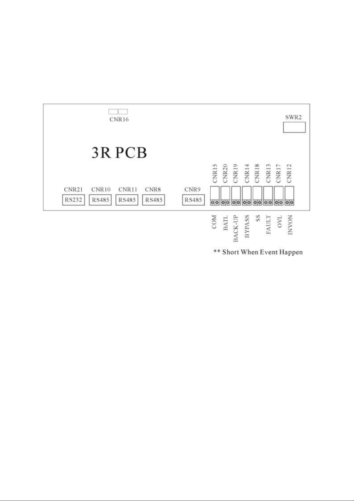
6. INTERFACE CONNECTIONS
All interfaces are connected from 3R PCB. See the figure below.
6.1. Dry Contacts
8 terminals of dry contacts are provided. These terminals are normally open (nonconducting). When an event occurs, the terminal will close (conduct). Maximum contact
rating is 16A/250VAC(16A/30VDC). The events are shown below.
INVON – Closed whenever the inverter is on, open when the inverter is off.
OVL – Closed whenever the ELI is overloaded.
6005-145 Rev. A 6-1
Page 68

FAULT –
Closed when the ELI encounters a fault condition, such as high DC
shutdown, short circuit, fuse/over-heat, overload shutdown, emergency
stop, inverter abnormal, bypass on shutdown. The contact is latched until
manual reset (off switch) or 30 seconds after the fault condition is
removed.
SS – Closed when the inverter static switch is conducting, open when the reserve
static switch is conducting (The two static switches will never conduct
simultaneously).
BYPASS – Closed when the maintenance bypass breaker is closed, open when the
breaker is opened.
BACK-UP –Closed when the inverter (running) is being backed up by the battery.
BATL – Closed when the inverter is using battery power and the batteries are about to
be exhausted.
COM –
This contact can be configured as the OR result of the signals described
above. SWR2-1 (dip-switch pin 1) ~ SWR2-7 (dip-switch pin 7) can
select one of the seven signals described above and SWR2-8 is the COM
enable switch. Please refer to the dip-switch of SWR2 on the 3R PCB
and the following examples and diagram.
6005-145 Rev. A 6-2
Page 69
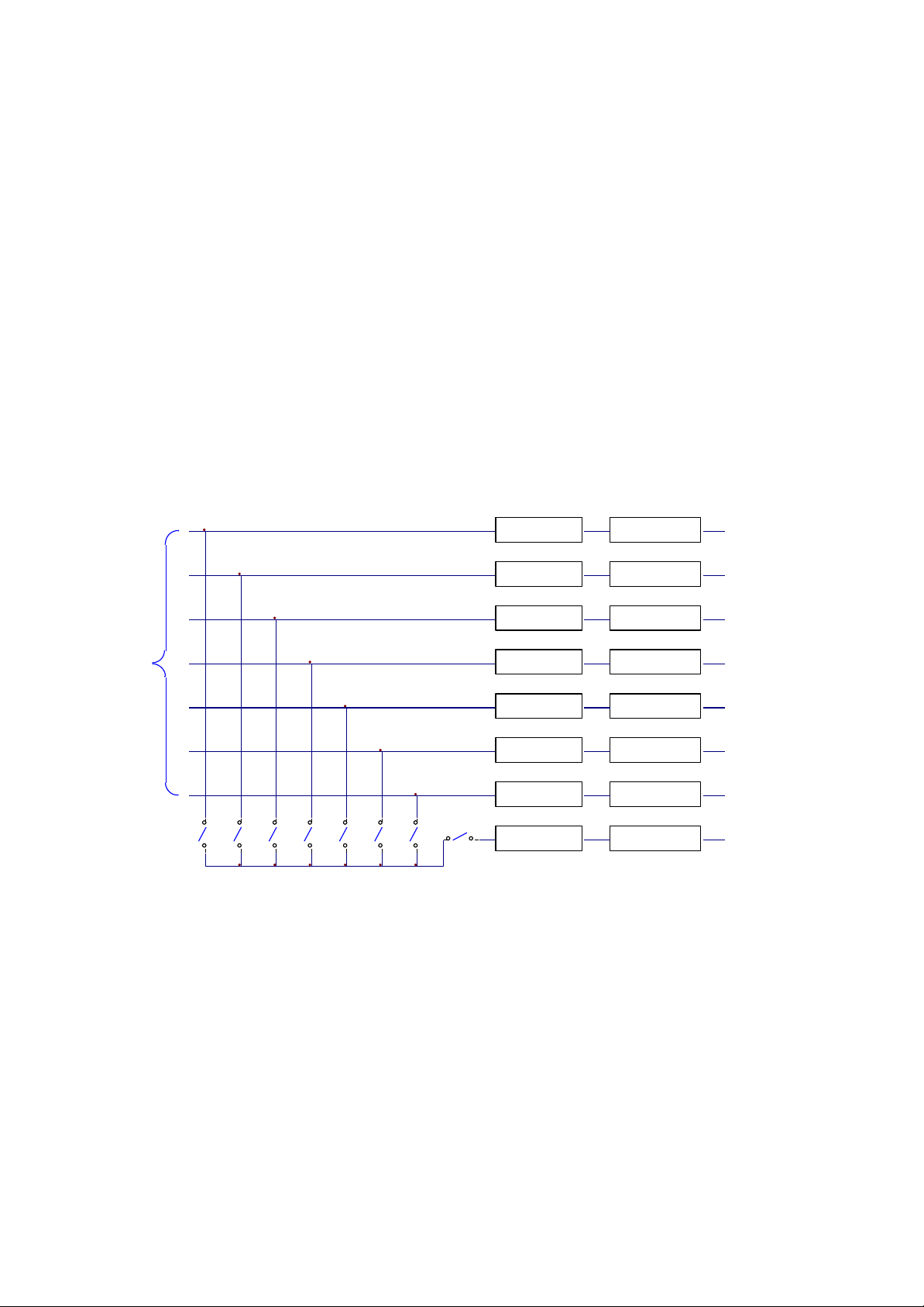
A
B
C
D
4321
SWR2-1
SWR2-2
SWR2-3
SWR2-4
SWR2-5
SWR2-6
SWR2-7
SWR2-8
RELAY CNR15
RELAY CNR20
RELAY CNR19
RELAY CNR14
RELAY CNR16
RELAY CNR13
RELAY CNR17
RELAY CNR12 INVON
INTERNAL
CIRCUIT
TO
OVL
FAULT
SS
BYPASS
BACK-UP
BATL
COM
SWR2-DIP SWITCH ON 3R PCB
Example 1:
If two contacts for BACK-UP are required. Switch on SWR2-6 & SWR2-8, then both
CNR19 & CNR15 will close when the unit goes to back-up.
Example 2:
If one contact for OVL & FAULT is required. Switch on SWR2-2 & SWR2-3, then the
CNR15 will close when either OVL or FAULT condition happens. Of course CNR17
will close when OVL happens and CNR13 will close when FAULT happens.
6005-145 Rev. A 6-3
Page 70

6.2. External Shutdown
2 pairs of terminals CNR 16 are provided for external shutdown. 10mA is needed for
turning on the internal photo-coupler. The user can use this terminal to shutdown the ELI
when emergency conditions occur, such as fire, short circuit etc.
6.3. DB9 Connection
Four RS-485 and one RS-232 are provided to communicate with more sophisticated
(option) modules. Each connector is especially dedicated to one type of external module.
The following are some connection examples of optional modules.
CNR21 (RS-232) ELICOM- Software for PC Monitoring、SNMP Card
CNR9 (RS-485) DCMAN- Battery Monitoring Module
CNR10 (RS-485) ELICAN- Remote Control Panel
CNR12,13,14,15,17,18,19 (RS-485) ELICALL- Auto Dialing Module
CNR11 for transferring RS-485 into RS-232
6005-145 Rev. A 6-4
Page 71
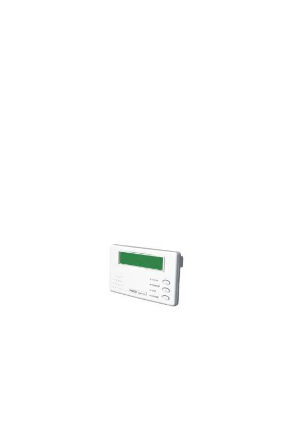
7. OPTIONS
This chapter supplies a brief introduction to all the options that are available for the 3
Phase ELI. Similar products from other manufacturer will not fit into this ELI.
Additionally, the installation of each option needs professional, trained personnel.
7.1 Emergency Power Off Switch (EPO) – OPTION FOR UL 1778 ONLY.
An emergency power off (EPO) switch is available as an option, installed outside but
nearby the ELI, for stopping the ELI output in case of emergency, such as electrical
shock, burning of the load or any emergency conditions where one wants to stop the
AC output immediately. When the EPO switch button is pushed, the inverter
immediately stops running, but the static switch remains tied to the inverter. Therefore
there will be no AC supply at the output. This shutdown condition will be latched until
it is manually reset by pressing the OFF () switch and inverter control switch ()
simultaneously.
Therefore, please first switch off INVERTER ( push right & middle of inverter switch
simultaneously) and then on INVERTER again (left & middle of inverter switch
simultaneously) to restart the ELI after the EPO is triggered.
7.2. Remote Control Panel – ELICAN
ELICAN, remote control panel, is a hand held display module with LCD (the same as
the LCD of the ELI). It is used to switch, on or off, any or all of the ELI systems. When
any ELI encounters an emergency condition, the system will warn the user
immediately. All the ELI status, data or commands are transmitted to external modules
through 4 RS-485 ports (for long distance communication under harsh environment).
ELICAN can monitor 1 to 99 units of ELIs with DB9 connections in series from
distance of up to 1000M.
6005-145 Rev. A
7-1
Page 72

7.3. Software for PC Monitoring – ELICOM
ELICOM is a hardware/software combination installed on a PC to monitor multiple
ELIs with DB9 connection in series. The connector on the ELI’s side is RS-485 (for
long distance transmission); therefore an RS-485 RS-232 adapter (hardware) is
required to modify the signal. The software and hardware together form a package
called ELICOM. See the ELICOMTM specification for further information.
7.4. Auto Dialing Module – ELICALL
In case abnormal situations occur, ELICALL
TM
will automatically dial specified phone
numbers to inform management to take prompt action. The module, with built-in
23A12V battery, consumes power only when in the process of dialing so as to be
operated under AC source failure. Furthermore, with functions of multiple phone
number setting and dialing, ELICALLTM has no need of dedicated lines, and can offer
user a prompt and convenient way for monitoring the ELI. See the ELICALLTM
specification for further information.
7.5. Battery Monitoring Module - DCMAN
DCMAN is an intelligent module for watching each individual battery in the
battery bank in a simple and direct way. DCMAN can distinguish for repair the
initially aged battery under safe conditions, thus prolonging the battery life
expectancy. One module can monitor up to 64 pieces of 12V battery. DCMAN
will sound an alarm in case of an abnormal situation, such as battery failure,
cable abnormal disconnection, or if the remaining battery charge is less than the
parameter set in the module. See the DCMAN specification for additional
information.
7.6. Input Transient Voltage Surge Suppressor (TVSS)
TVSS is a DIN rail mounted device, connected to the Inverter input. Its plugin phase modules are easily replaceable. The device contains energy
absorbing components and has a two-stage protection. When a protection component is
damaged by absorbed transient, the module will display a flag indicating a need for
replacement.
6005-145 Rev. A
7-2
Page 73

7.7 Web/SNMP Card:
This option is a web enabled monitoring device for a
unit with Internet or network connection. The SNMP/Web card can monitor the
Inverter on the network through a standard web browser.
7.8 Output Aux Circuit breakers
7.9 Higher kAIC Circuit breakers
7.10 Delta Input
7.11 Dual input
7.12 Seismic Bracket
7.13 Factory Set Green Mode
6005-145 Rev. A
7-3
Page 74
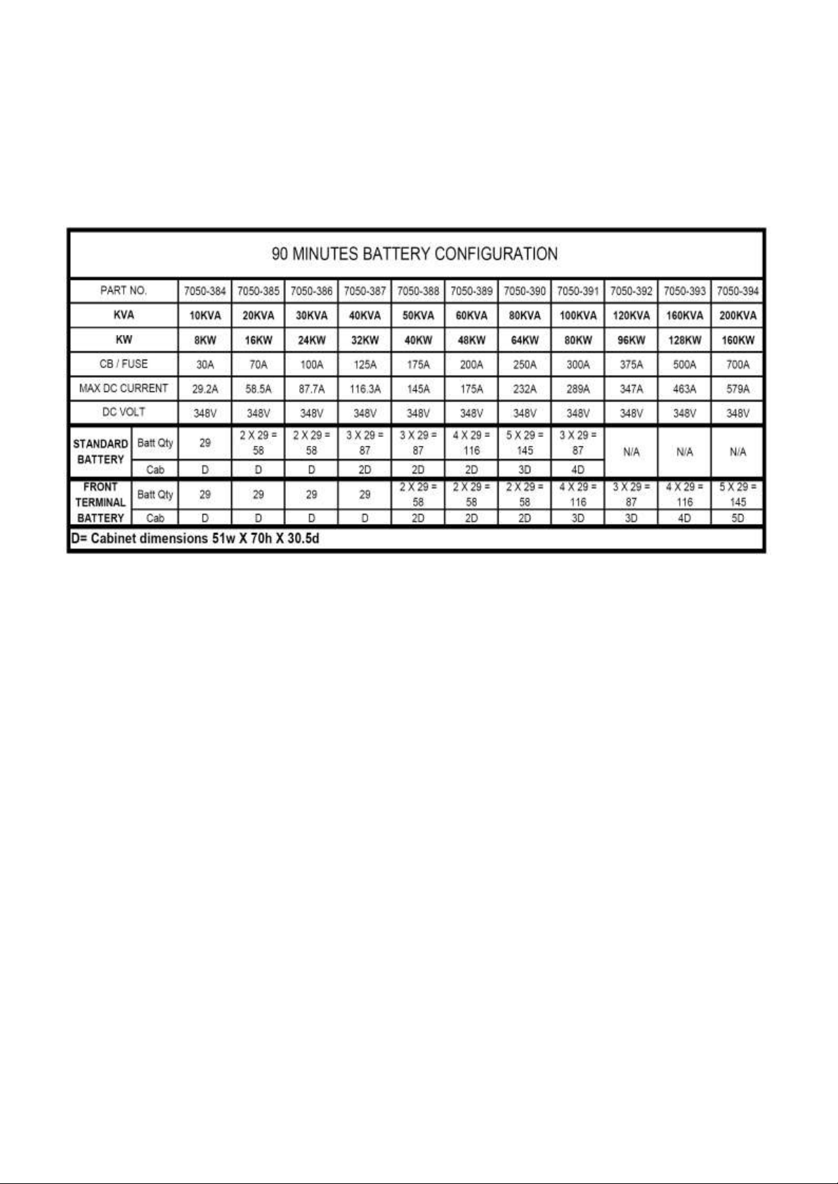
7.14 Battery cabinet and battery run time.
90 minutes (UL924) battery charts.
(Battery cabinets, painted black)
6005-145 Rev. A
7-4
Page 75
BATTERY CONFIGURATION, UL 1778: 5 MIN~60 MIN
PART NO.
7050-384
7050-385
7050-386
7050-387
7050-388
KVA
10KVA
20KVA
30KVA
40KVA
50KVA
KW
8KW
16KW
24KW
32KW
40KW
TIME IN MINUTES
-005
29X17AH
C
29X25AH
C
29X35AH
C
29X50AH
C
29X65AH
C
-010
29X17AH
C
29X35AH
C
29X50AH
C
29X80AH
2C OR D
29X90AH
2C OR D
-015
29X25AH
C
29X35AH
C
29X50AH
C
29X90AH
2C OR D
29X100AH
2C OR D
-020
29X25AH
C
29X50AH
C
29X80AH
2C OR D
29X100AH
2C OR D
29X120AH
2C OR D
-030
29X35AH
C
29X65AH
C
29X100AH
2C OR D
29X120AH
2C OR D
58X80AH
3C OR D
-045
29X50AH
C
29X100AH
2C OR D
58X80AH
3C OR D
58X100AH
3C OR D
58X120AH
3C OR D
-060
29X50AH
C
29X110AH
2C OR D
58X80AH
3C OR D
58X110AH
3C OR D
87X100AH
4C OR 2D
CB / FUSE
30A
70A
100A
125A
175A
MAX DC CURRENT
29.2A
58.5A
87.7A
116.3A
145A
DC VOLT
348V
348V
348V
348V
348V
PART NO.
7050-389
7050-390
7050-391
7050-392
7050-393
7050-XXX
KVA
60KVA
80KVA
100KVA
120KVA
160KVA
200KVA
KW
48KW
64KW
80KW
96KW
128KW
160KW
TIME IN MINUTES
-005
29X80AH
2C OR D
29X90AH
2C OR D
29X120AH
2C OR D
58X80AH
3C OR D
58X90AH
3C OR D
58X120AH
3C OR D
-010
29X90AH
2C OR D
29X120AH
2C OR D
58X90AH
3C OR D
58X90AH
3C OR D
58X120AH
3C OR D
87X100AH
4C OR 2D
-015
29X120AH 2C
OR D
58X90AH
3C OR D
58X100AH
3C OR D
58X120AH
3C OR D
87X100AH
4C OR 2D
87X120AH
4C OR 2D
-020
58X80AH
3C OR D
58X100AH
3C OR D
58X120AH
3C OR D
87X100AH
4C OR 2D
87X 120AH
4C OR 2D
116X100AH
5C OR 2D
-030
58X100AH
3C OR D
58X120AH
3C OR D
87X100AH
4C OR 2D
87X120AH
4C OR 2D
116X120AH
5C OR 2D
145X120AH
6C OR 3D
-045
87X90AH
4C OR 2D
87X120AH
4C OR 2D
116X120AH
5C OR 2D
145X120AH
6C OR 3D
145X150AH
8C OR 4D
174X150AH
9C OR 4D
-060
87X120AH
4C OR 2D
116X100AH
5C OR 2D
145X100AH
6C OR 3D
145X120AH
6C OR 3D
145X200AH
7D
174X150AH
9C OR 4D
CB / FUSE
200A
250A
300A
375A
500A
700A
MAX DC CURRENT
175A
232A
289A
347A
463A
579A
DC VOLT
348V
348V
348V
348V
348V
348V
C=Cabinet dimensions 39w X 68h X 18d
D=Cabinet dimensions 51w X 70h 30.5d
Standard battery cabinet configuration, depending on customer spacing other size cabinet or racks could be useds
Other than 90 minutes, UL1778
6005-145 Rev. A
7-5
Page 76
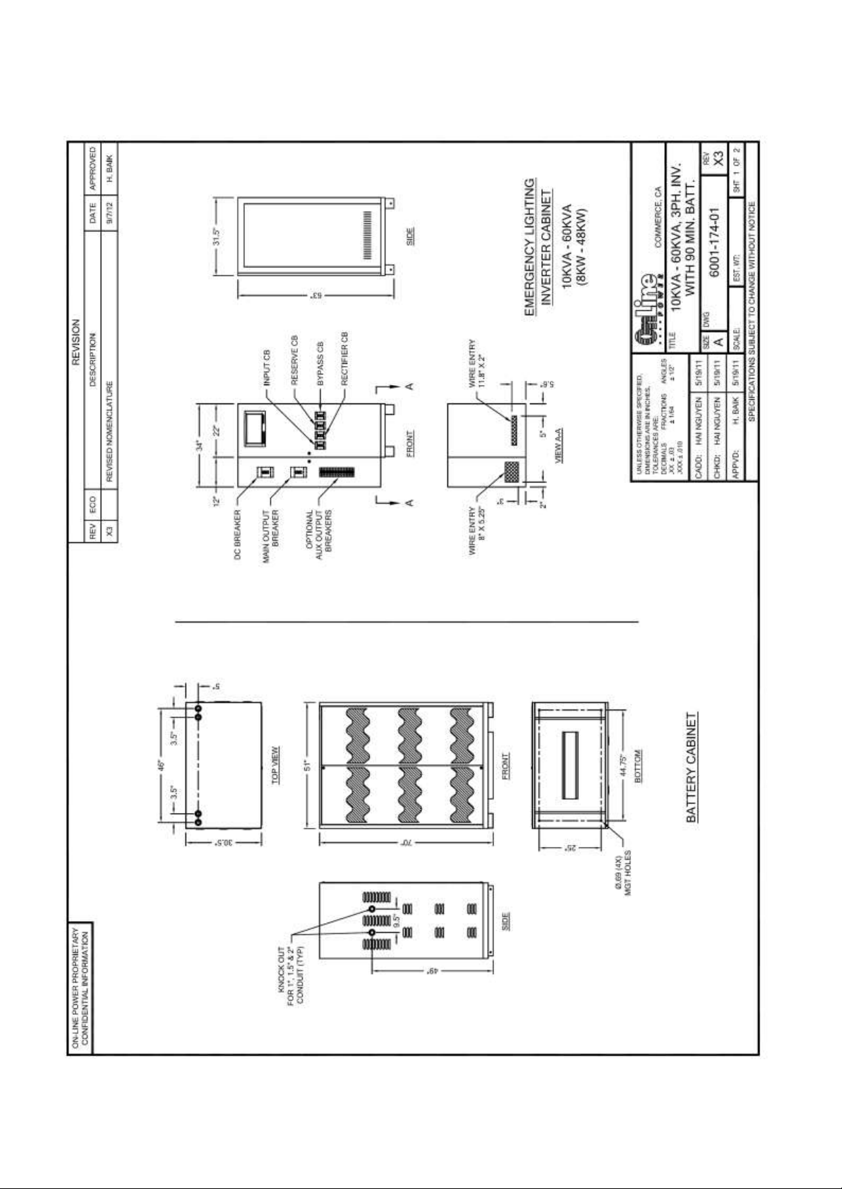
7.15 Battery Cabinets Arrangement Drawings.
6005-145 Rev. A
7-6
Page 77
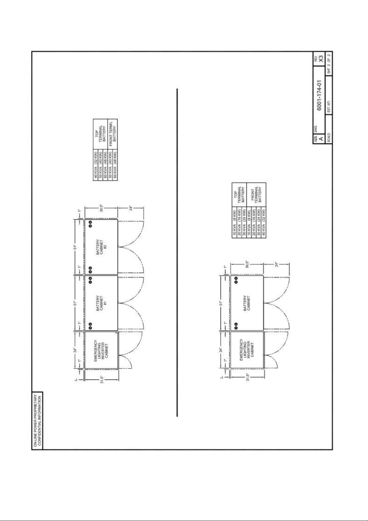
(continue) Battery Cabinets Arrangement Drawings.
6005-145 Rev. A
7-7
Page 78
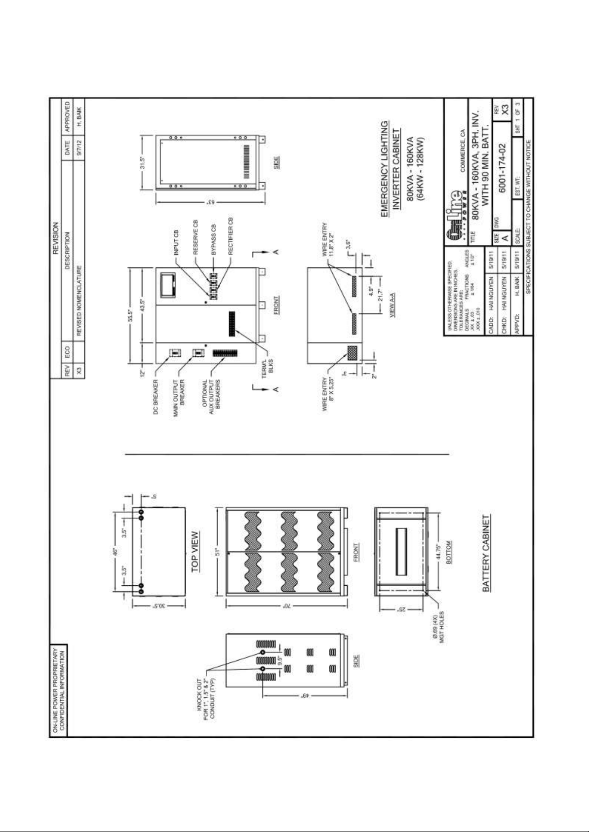
(continue) Battery Cabinets Arrangement Drawings.
6005-145 Rev. A
7-8
Page 79
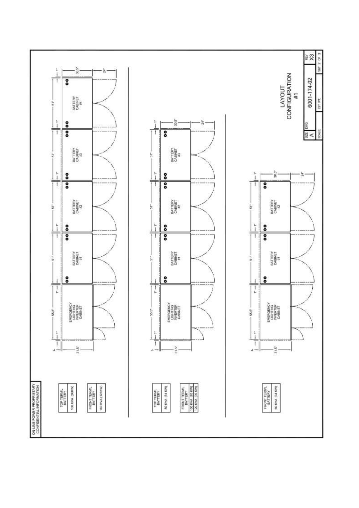
(continue) Battery Cabinets Arrangement Drawings.
6005-145 Rev. A
7-9
Page 80
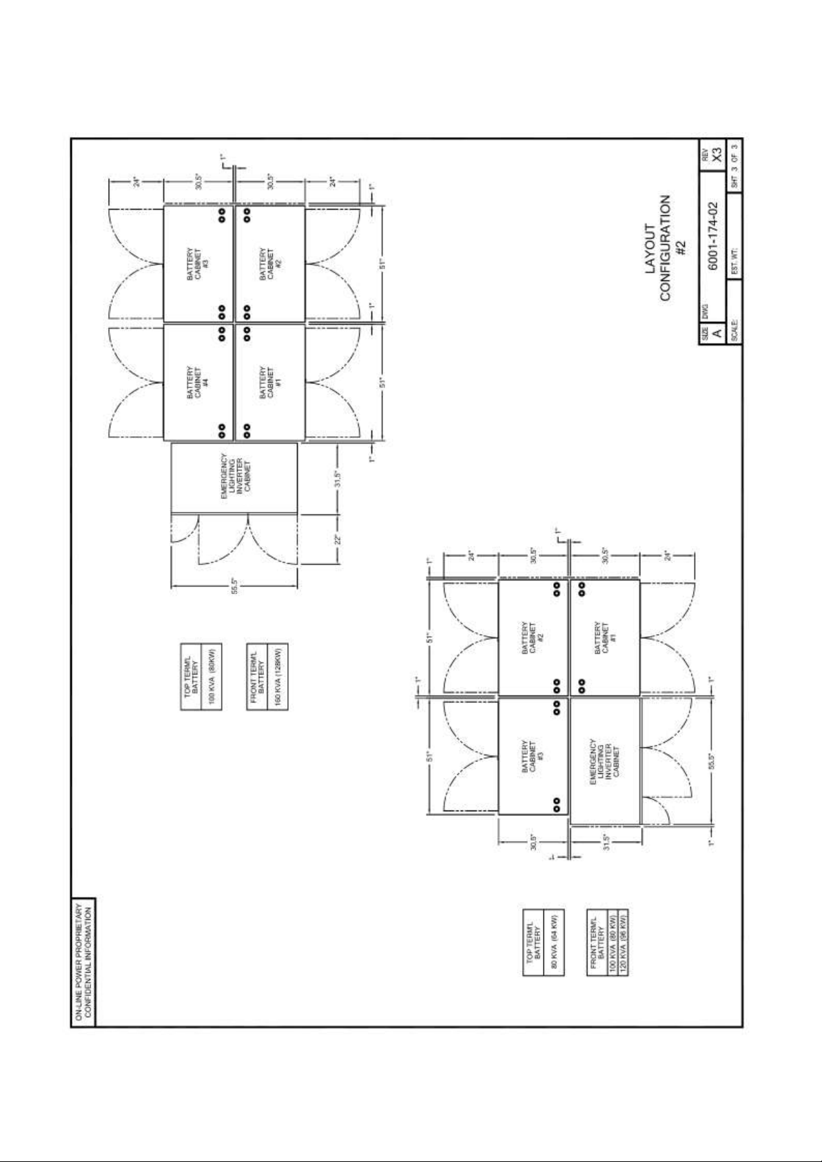
(continue) Battery Cabinets Arrangement Drawings.
6005-145 Rev. A
7-10
Page 81
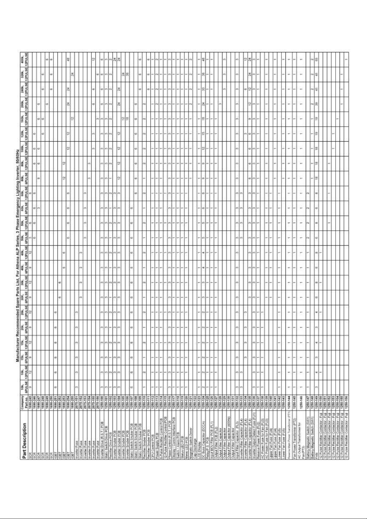
7.16 Replaceable parts list.
6005-145 Rev. A
7-11
Page 82
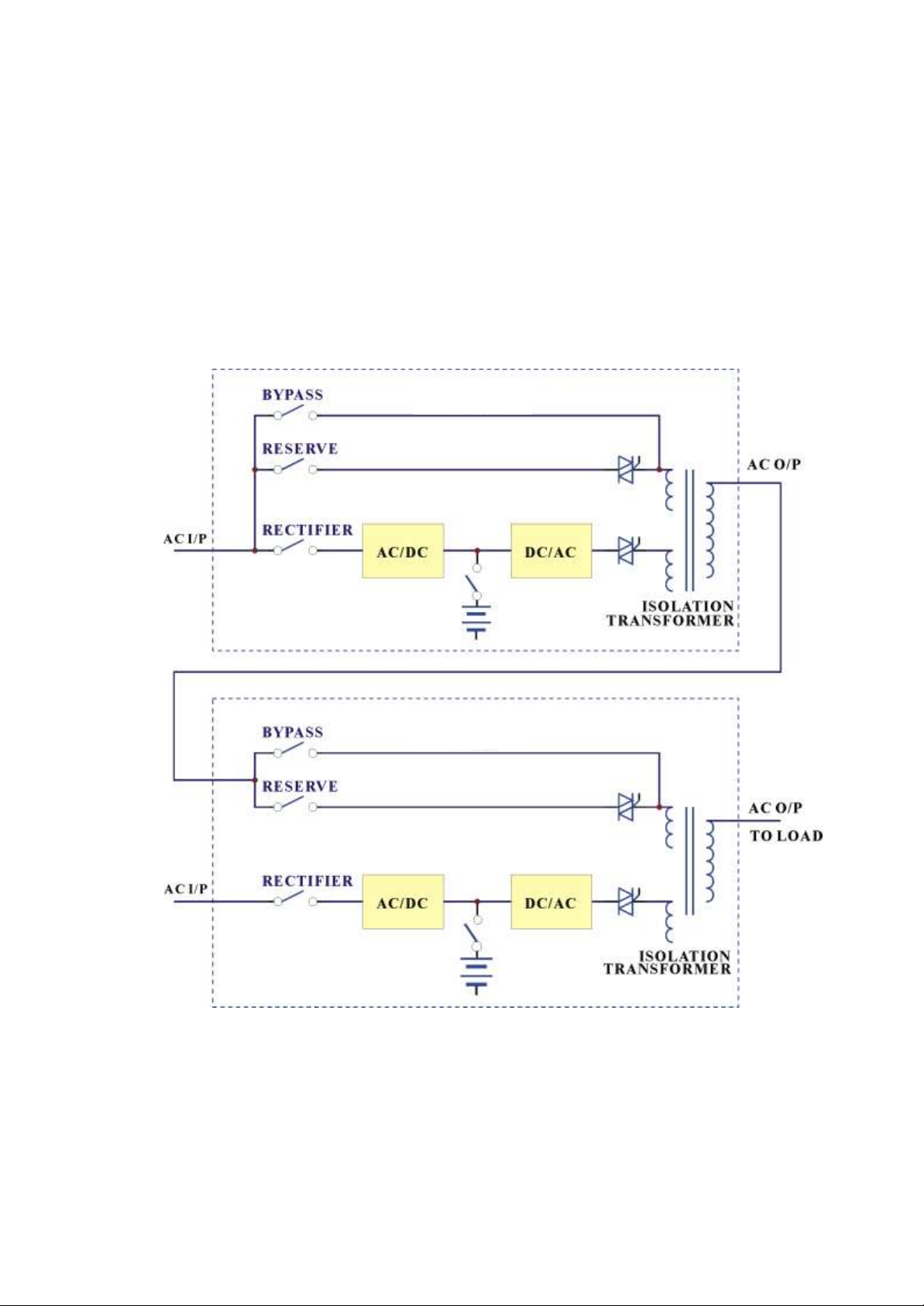
ELI 1
ELI 2
8. REDUNDANCY
Redundancy can be roughly divided in two types: serial (hot standby) redundancy and
parallel (active) redundancy. The ELI series adopts mainly serial redundancy.
8.1. Serial Redundancy
6005-145 Rev. A
8-1
Page 83

ONE TO ONE SERIAL REDUNDANCY
Serial (hot standby) redundancy consists of two ELI with one ELI’s (ELI1)
connected to the reserve/bypass input of the other ELI (ELI2). See the above figure.
Both ELIs are running in normal mode under normal conditions. When one of them
has a problem, the load will still have protection from the inverter and battery. If
ELI1 fails and ELI2 is running normally, the load is unaffected, and supplied from
ELI2. If ELI2 fails and ELI1 is running normally, ELI2 will transfer the load to
ELI1 and the load will continue to be protected by the inverter and battery of ELI1.
If both of them are running normally, ELI2 takes up all load and ELI1 bears no load.
Therefore, ELI1 has a longer MTBF than ELI2 (can be interchanged after a period
of time), and their MTBF multiplies to a very large MTBF.
This type of redundancy is employed most frequently. When mains fail, ELI2 is the
first to contribute its battery to back-up the load. When ELI2’s batteries are
exhausted, the load is transferred to ELI1. Therefore, this topology can make full
use of the batteries of both units. Users get a system that has redundant protection
and double the back-up time.
Another less expensive solution (see the figure below) is available if the load is
separated. A user may intend to install two ELIs, each with the same power, and
supplying half the load. A third ELI can be installed as backup to two main ELIs. It
is statistically improbable that both main ELIs concurrently break down. Therefore,
the third ELI can serve as a hot standby to two ELIs.
These topologies make full use of the resources to create the best protection and
longest MTBF.
6005-145 Rev. A
8-2
Page 84
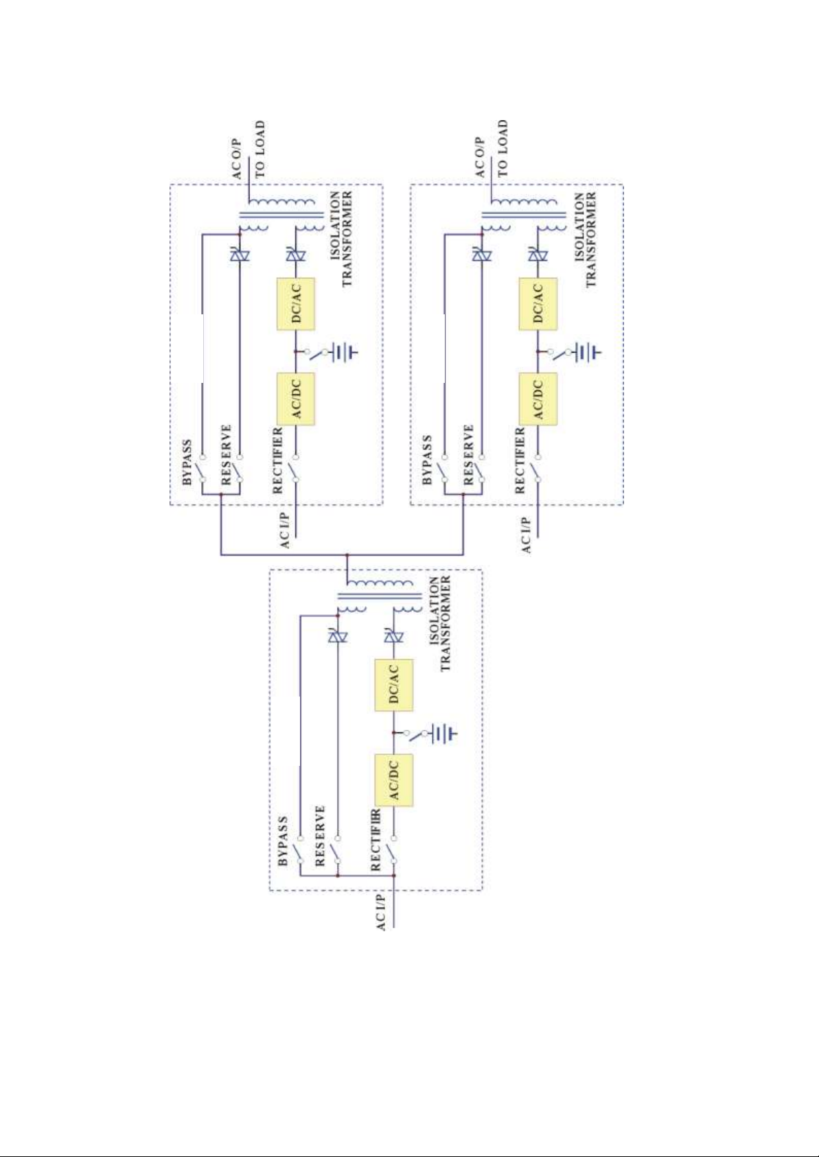
ELI 2
ELI 1
ELI 3
ONE TO TWO SERIAL REDUNDANCY
6005-145 Rev. A
8-3
Page 85
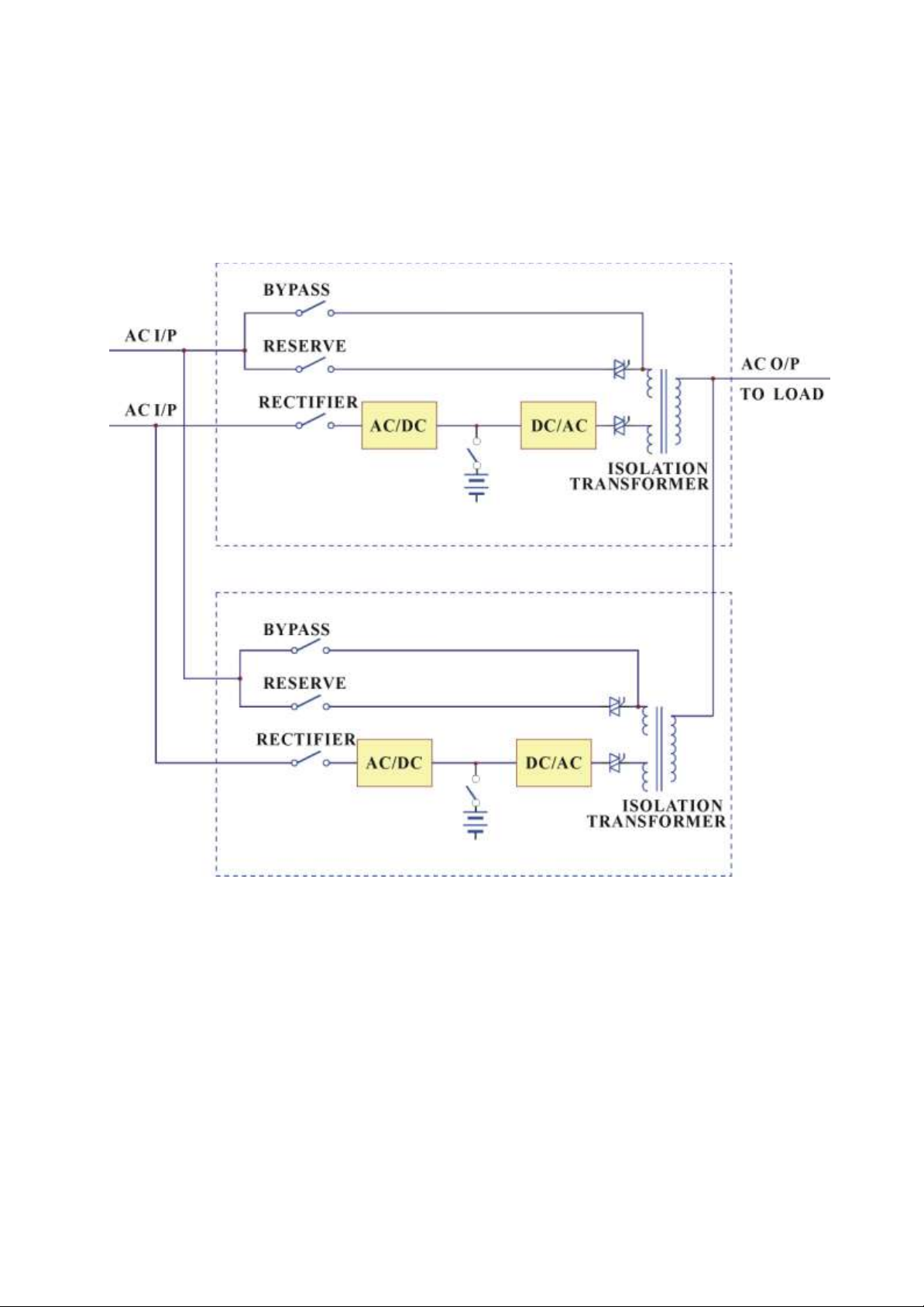
ELI 1
ELI 2
8.2. Parallel Redundancy
The parallel redundancy configuration, like below figure, is designed to increase
both the capacity and reliability. And all the ELI are sharing with equal load.
6005-145 Rev. A
8-4
Page 86
Danger!
READ AND UNDERSTAND THIS SECTION THOROUGHLY BEFORE
PERFORMING ANY MAINTENANCE WORK ON OR AROUND THE UNIT. READ
THE BATTERY MANUFACTURER’S MANUAL AND MATERIAL SAFETY DATA
SHEETS BEFORE WORKING ON OR NEAR THE BATTERIES.
ONLY NORMAL SAFETY PRECAUTIONS ARE REQUIRED WHEN THE UNIT IS
OPERATING WITH ALL CABINET DOORS CLOSED. HOWEVER, THE UNIT
AND BATTERY CABINETS MUST BE KEPT FREE OF STANDING PUDDLES OF
WATER, EXCESS MOISTURE, OR DEBRIS. DEBRIS CONSISTING OF
EXCESSIVE DUST IN AND AROUND THE UNIT WILL BE PULLED INTO THE
UNIT BY THE COOLING FANS.
Danger!
ONLY FACTORY TRAINED OR AUTHORIZED PERSONNEL SHOULD ATTEMPT
TO INSTALL OR REPAIR THE UNIT OR ITS BATTERY SYSTEM. IMPROPER
INSTALLATION HAS PROVEN TO BE THE SINGLE MOST SIGNIFICANT CAUSE
OF START-UP PROBLEMS. SERVICE PERSONNEL SHOULD WEAR
INSULATING SHOES FOR ISOLATION FROM DIRECT CONTACT WITH THE
FLOOR (EARTH GROUND), AND SHOULD MAKE USE OF RUBBER MATS
WHEN PERFORMING MAINTENANCE ON ANY PORTION OF THE UNIT WHILE
IT IS UNDER POWER. HIGH AC AND DC ELECTRICAL VOLTAGES ARE
PRESENT THROUGHOUT THE UNIT (S) AND INCORRECT INSTALLATION OR
SERVICING COULD RESULT IN ELECTROCUTION, FIRE, EXPLOSION, OR
EQUIPMENT MALFUNCTION.
Danger!
SPECIAL SAFETY PRECAUTIONS AND LOCKOUT TAGOUT PROCEDURES
ARE REQUIRED FOR ALL OPERATIONS INVOLVING THE HANDLING,
INSTALLATION, OR MAINTENANCE OF THE UNIT SYSTEM AND ANY
ASSOCIATED BATTERY CABINETS. FAILURE TO FOLLOW SAFETY
PROCEDURES COULD RESULT IN DEATH, INJURY OR DAMAGE TO
EQUIPMENT.
9.
MAINTENANCE
9.1 SA
FETY PRECAUTIONS
The ELI requires regularly schedule periodic maintenance.
6005-145 Rev. A
9-1
Page 87
Danger!
THIS EQUIPMENT CONTAINS CIRCUITS THAT ARE ENERGIZED WITH HIGH
VOLTAGES. ONLY TEST EQUIPMENT DESIGNED FOR TROUBLESHOOTING
HIGH VOLTAGES SHOULD BE USED, PARTICULARLY FOR OSCILLOSCOPES
AND PROBES.
ALWAYS CHECK WITH AN AC AND DC VOLTMETER TO ENSURE SAFETY
BEFORE INITIATING CONTACT OR USING TOOLS. EVEN WHEN THE POWER
IS OFF, DANGEROUSLY HIGH POTENTIAL VOLTAGES MAY EXIST AT
CAPACITOR BANKS. ALWAYS OBSERVE BATTERY PRECAUTIONS WHEN
OPERATING NEAR ANY BATTERIES.
FAILURE TO OBSERVE THESE PRECAUTIONS COULD RESULT IN DEATH,
INJURY OR DAMAGE TO EQUIPMENT.
Danger!
OBSERVE ALL BATTERY SAFETY PRECAUTIONS DURING INSTALLATION OR
SERVICE OF THE UNIT OR BATTERIES. EVEN WITH THE BATTERY CIRCUIT
BREAKER IN THE OFF POSITION, THE DANGER OF ELECTROCUTION MAY
STILL BE PRESENT. THE BATTERY POWER TO THE UNIT MUST BE LOCKED
AND TAGGED “OFF” BEFORE PERFORMING ANY SERVICE OR WORK ON THE
UNIT. THE BATTERY MANUFACTURER’S SAFETY INFORMATION AND
MATERIAL SAFETY DATA SHEET IS LOCATED IN A POCKET ATTACHED TO
THE INSIDE OF LEFT DOOR OF EACH UNIT. FAILURE TO FOLLOW THOSE
INSTRUCTIONS AND THE INSTRUCTION LISTED ABOVE AND ELSEWHERE IN
THIS MANUAL COULD RESULT IN AN EXPLOSION, FIRE, EQUIPMENT
MALFUCTION, OR ELECTROCUTION.
Danger!
BE CONSTANTLY AWARE THAT THE UNIT SYSTEM CONTAINS HIGH DC AS
WELL AS AC VOLTAGES. WITH INPUT POWER OFF AND THE BATTERY
DISCONNECTED, HIGH VOLTAGE AT THE FILTER CAPACITORS AND POWER
CIRCUITS SHOULD DISCHARGE WITHIN 30 SECONDS. HOWEVER, POWER
CIRCUIT MALFUNCTIONS CAN OCCUR, SO YOU SHOULD ALWAYS ASSUME
THAT HIGH VOLTAGE MIGHT STILL EXIST AFTER SHUTDOWN. VERIFY THAT
POWER IS OFF USING AC AND DC VOLTMETERS BEFORE MAKING CONTACT.
6005-145 Rev. A
9-2
Page 88
Danger!
LETHAL VOLTAGES ARE PRESENT INSIDE THE EQUIPMENT EVEN
WHEN THERE APPEARS TO BE NO INPUT POWER TO THE UNIT.
PROTECT YOURSELF FROM THE RISK OF ELECTROCUTION BY
REFERRING SERVICE TO QUALIFIED PERSONNEL ONLY.
9.2 WHEN TO CALL (1-800-PWR-SRVC – 1-800-797-7782)
Call for service if you encounter any of the following conditions:
1) Repeated start-up attempts are unsuccessful.
2) A unit fault occurs which cannot be cleared.
3) Normal operation of the critical load repeatedly causes an overload condition.
This is not a unit fault but a qualified person must analyze the total load
connected to the unit to prevent malfunction. Momentary overload conditions
will be handled within the parameters of the unit but sustained overloads will
cause failure.
4) Any indicators or alarms operate abnormally or continuously.
5) Any other abnormal function of the system occurs.
6) If any abnormal battery condition is detected.
7) When you are unsure of what action to take.
9.3 STEPS TO TAKE
If any of the above occur:
1) Consult Appendix C, LCD Display Menu and Troubleshooting Guide. Record
information on the LCD Display to relay to OnLine Power Customer Service and
Support.
2) Call OnLine Power Customer Support at 1-800-797-7782 or 1-800-PWR-SRVC.
6005-145 Rev. A
9-3
Page 89

Preventive Maintenance List
Description
Visual inspection
Check Room Temperature
Removal of dust from all electronics
Verification of all electrical connection
Check all Batteries post and connection for corrosion
Check for batteries deformations
Record all batteries Nominal Voltages
Record all batteries Floating Voltages
Functional Test of all major components
Functional test of all electronics
Functional Test of system including batteries
Record all findings
9.4 PREVENTATIVE MAINTENANCE
The unit maintenance consists of the basic tasks listed in this section. Other
maintenance functions require OnLine Power factory trained service personnel. In
order to comply with the terms of the prorated battery warranty, you must maintain
at least an annual individual voltage record of each battery with evidence that the
terminal connections have been torque checked.
9.4.1 Maintenance Log
Carefully record keeping will ensure proper maintenance of the unit, and assist in
the correction of any abnormal conditions.
At a minimum, the Maintenance log should contain the following information:
Date of system start-up.
Dates that battery maintenance was performed.
Dates input, output, and battery status readings were checked and the values
displayed for these readings.
Date of load changes.
Dates and summaries of all communications with OnLine Power service
personnel.
Every six (6) months or at least annual, individual battery voltage & torque check.
6005-145 Rev. A
9-4
Page 90
Danger!
THE BATTERY CIRCUIT BREAKER OPERATES AT THE RATED BATTERY
VOLTAGES AT ALL TIMES. A TRIPPED BATTERY CIRCUIT BREAKER
INDICATES A SERIOUS PROBLEM THAT MAY RESULT IN SERIOUS INJURY
OR DAMAGE TO THE EQUIPMENT; DO NOT CLOSE THE CIRCUIT BREAKER
WITHOUT KNOWING WHY IT FAILED. CHECK FOR A SHORT IN BATTERY OR
CONNECTIONS. CALL ONLINE POWER CUSTOMER SERVICE AND SUPPORT
FOR ASSISTANCE AT 1-800-PWR-SRVC.
Danger!
THE BATTERY ELECTROLYTE IS A DILUTED SULFURIC ACID THAT IS
HARMFUL TO THE SKIN AND EYES. IT IS ELECTRICALLY CONDUCTIVE AND
CORROSIVE. WEAR FULL EYE AND HAND PROTECTION ALONG WITH
PROTECTIVE CLOTHING. IF THE ELECTROLYTE CONTACTS THE SKIN,
WASH IT OFF IMMEDIATELY WITH WATER. IF ELECTROLYE CONTACTS
THE EYES, FLUSH THOROUGHLY AND IMMEDIATELY WITH WATER. SEEK
IMMEDIATE MEDICAL ATTENTION. SPILLED ELECTROLYTE SHOULD
ADDRESSED PER APPROPRITE HARADIDEROUS SPILL CLEANUP
PROCEDURES.
Danger!
DO NOT DISPOSE OF A BATTERY OR BATTERIES IN A FIRE.
THE BATTERIES MAY EXPLODE CAUSING DEATH OR SERIOUS INJURY.
9.4.2 Periodic Testing of unit
The unit should be manually exercised on a periodic basis (once every three
months, for example). This forces the unit to transfer to the battery and return to
main power. This process activates self-diagnostic testing, which may reveal
conditions that require attention.
9.4.3 Maintaining the Batteries
6005-145 Rev. A
9-5
Page 91
Caution
Caution
Caution
Caution
Danger!
DO NOT GROUND BATTERY POSITIVE OR NEGATIVE
Caution
Do not substitute batteries from other manufacturers without the express
approval of OnLine Power Customer Service personnel.
● The use of any battery other than Online-Power may cause damage to the
inverter and voids your Online-Power warranty.
Lead-acid batteries contain hazardous materials and must be handled,
transported, and recycled or scrapped in accordance with federal, state and
local regulations. Since lead is a toxic substance, lead-acid batteries should
be recycled rather than scrapped.
A battery can present a risk of electrical short and high short circuit
current. The following precautions should be observed when working on or
around batteries:
● Remove watches, rings, necklaces, or other metal objects.
● Use only tools with insulated handles.
● Wear rubber insulating gloves and boots.
● Do not lay tools or metal parts on top of batteries.
● Disconnect charging source prior to connecting or disconnecting
battery terminals.
● Verify that battery cabinets are properly grounded.
Lead-acid batteries can present a risk of fire because they generate hydrogen
gas. The following safety procedures must be followed:
● DO NOT SMOKE when near batteries.
● DO NOT cause flame or sparks in battery areas.
● Discharge static electricity from your body before touching
batteries by first touching a grounded metal surface.
When replacing batteries, use the same number of batteries, of the same
manufacturer, type and model that was supplied with the unit. To avoid
system malfunction, replace all batteries in each string if one or more batteries
fail to perform to specifications. Please record all individual cell voltages on the
chart.
6005-145 Rev. A
9-6
Page 92

Battery part number
Initial torque in LBS
Annual re-torque in LBS
Terminal Type
Hardware
PRC-12150 C
(150AH)
120 IN-LB / 13.6 NM
115 IN-LB / 13.6 NM
Copper Insert
Terminal
¼ - 20 UNC Bolt
UB 12750
88.5 IN-LB / 10 NM
84 IN-LB / 9.5 NM
Z1 "Z" post
type terminal
1 to 1.25" long bolt
w/14mm head, 14mm nut,
8mm washer & lockwasher
UB12900
88.5 IN-LB / 10 NM
84 IN-LB / 9.5 NM
Same as above
Same as above
UB12110
88.5 IN-LB / 10 NM
84 IN-LB / 9.5 NM
Same as above
Same as above
Battery part number
Initial torque in LBS
Annual re-torque in LBS
Terminal Type
Hardware
GSLF – 10512
120 IN-LB / 13.6 NM
115 IN-LB / 13.0 NM
Copper Insert
¼ "
GSLF - 12012
120 IN-LB / 13.6 NM
115 IN-LB / 13.0 NM
Copper Insert
¼ "
Ni-Cad P/N
Recommended Torque
Bolt Diameter
BM 112/ 138
66 IN-LB
7.5 NM
M5
BM 148/ 184
177 IN-LB
20 NM
M8
BM 195/231/277
266 IN-LB
30 NM
M10
NOTE: For annual re-torque; reduce 5 IN-LB from recommended torque value.
9.4.4 Battery Cabinets
Although the individual batteries are sealed and require minimal maintenance only, the
batteries should be given a periodic inspection and electrical check every six months.
Battery Service Agreements are available through OnLine Power Customer Service and
Support at 1-800-PWR-SRVC (800-797-7782).
In order to qualify for battery warranty replacement, you will need to show records of the
battery maintenance history including battery numbers, battery voltages (individual cells),
terminal torque measurements and dates of maintenance.
9.4.5 Power Connections
Check for corrosion and connection integrity. Visually inspect wiring for discolored or
cracked insulation. Clean and / or re-torque as required.
All Battery terminal connections must be tighten with proper torque value set in
accordance with the table or instructions provided by battery manufacturer.
Use the correct torque tool to tighten the terminal bolts as indicate d in table below and
use all hardware's provided with batteries.
Type – Standard VRLA Battery
Type G – Longer warranty battery
Type N – Nickel-Cad battery (only nickel plated copper cable lugs should be used).
CAUTION: Torque all connections in accordance with the above tables unless provided from battery
manufacturer. Failure to do so may create an unsafe condition or fire hazard.
6005-145 Rev. A
9-7
Page 93

9.4.6 Battery Terminals
Check for discoloration, corrosion and connection integrity. Clean and tighten as
necessary.
To access battery terminals, remove the top strapping material located at the lower
front of the battery shelf. Pull the battery forward to access the battery connections.
Disconnect the cables connected to the battery. Once disconnected, insulate the cables
to prevent accidental shorts (Use a protective boot or electrical tape). Before replacing
the battery connections clean and re-torque the connection hardware.
OnLine Power Customer Service personnel must approve use of non-standard batteries.
Please call at 1-800-PWR-SRVC (800-797-7782).
9.5 ONLINE POWER CUSTOMER SERVICE AND SUPPORT
Start-up, unit maintenance, battery maintenance, and preventative maintenance programs
are available through your OnLine Power sales representative or through OnLine Power
Customer Service and Support. A program of periodic maintenance is recommended
once every six months, but is mandatory once every twelve months since heat and cold
will effect the compression of the electrical connections and lack of maintenance will
shorten the product's life expectancy possibly causing unsafe operating condition.
9.5.1 Start-Up Services
Various start-up services are available. See your sales representative or telephone OnLine
Power Customer Service at 1-800-PWR-SRVC (800-797-7782).
9.5.2 Maintenance Agreements
Standard Full Service, 24/7 Full Service, and Extended On or OFF Site Maintenance
agreements are available. See your sales representative or telephone OnLine Power
Customer Service at 1-800-PWR-SRVC (800-797-7782).
9.5.3 Warranties
Contact OnLine Power Customer Service and Support at 1-800-PWR-SRVC (800-797-
7782) if you have any questions regarding the warranty on your unit, system or batteries.
6005-145 Rev. A
9-8
Page 94

Abnormal
Description & Checkpoint
Solution
(1) AC input is
correct, but
rectifier does
not operate and
RECT AC
FAIL LED
lights up.
The rectifier breaker is not switch on.
Switch on the rectifier
breaker.
The input voltage is not correct (out of the
normal range).
Connect the right AC
source.
The phase sequence of AC input is
incorrect, input rotation error, and the
LCD will display warning message
“RECT PHASE ERROR” in the
STATUS/WARN menu (MAIN menu →
SELECT menu → STATUS/WARN
menu). ROTATION ERROR LED on left
side of the front panel will also light.
Correct the R.S.T. phase
sequence. Generally, to
exchange any two phases
connection can solve this
problem.
If the abnormality cannot be corrected
when the solution actions have been
taken.
Refer to PCB LED
Detecting Guide and check
the 3C PCB.
(2) The ELI
shuts down
under AC
mains failure.
The battery fuse (breaker/holder/disconnector) has not been closed.
Close the battery fuse
breaker/holder/disconnector.
(3) No power
supply for ELI
control circuit
and LCD
cannot display.
The reserve breaker has not been closed
(switched on).
Close the reserve breaker.
3B PCB has problem.
Refer to PCB LED
Detecting Guide and check
the 3B PCB.
9.5.4 HELP
Followings are some abnormal situations frequently asked and common solution
is offered for trouble-shooting.
6005-145 Rev. A
9-9
Page 95

Abnormal
Description & Checkpoint
Solution
(4) The voltage
difference
between
NEUTRAL
and GROUND
has become
abnormally
high.
There is external wiring error of R.S.T
phase and N. G., instead of ELI unit
itself,.
Correct the external wiring
system.
(5) The
inverter cannot
start up.
Other than INVERTER SS LED in left
side of the front panel, other LEDs still
illuminate.
Do trouble shooting
according to the LED
instruction.
Switch on the inverter before DC bus has
been established completely. Normally, it
takes around 30 seconds to establish the
DC BUS once the reserve and rectifier
breakers are closed.
Refer to the switch on
procedure. Close the
reserve and rectifier
breakers and wait around
30 seconds or directly use
batteries to establish the DC
bus.
Bypass breaker has been closed
(switched on).
Open the bypass breaker.
The output is overloaded. The LCD will
display warning message ‘ XXX%
OVERLOAD’ in the STATUS/WARN
menu (MAIN menu → SELECT menu
→ STATUS/WARN menu). XXX%
OVERLOAD LED on left side of the
front panel and OVERLOAD LED on
right side will also light.
Decrease the load to below
the ELI’s rated power.
In P&P modules1, the temperature sensor
sockets on 3G PCB and hest sink are not
connected properly. WARNINGLED of
FUSE/TEMP still illuminate but LED in
3G PCB doesn’t, indicating DC BUS
may be over 240VDC.
Take out the P&P modules
and connect them properly.
6005-145 Rev. A
9-10
Page 96

Abnormal
Description & Checkpoint
Solution
(6) Fans do not
work while
ELI is on.
The fuses positioned behind PCB holder
have been blown or are not installed
properly.
Replace the fuses or install
them properly.
Abnormal voltage output in R phase.
Refer to PCB LED
Detecting Guide and check
the 3T PCB of R phase.
(7) The
rectifier shunt
down and
HIGH DC
LED is lit.
Voltage limit function failure in the 3B,
which contributes to the DC voltage,
goes over 430V.
Refer to PCB LED
Detecting Guide and check
the 3B PCB.
3C PCB has problem.
Refer to PCB LED
Detecting Guide and check
the 3C PCB.
(8) Abnormal
voltage in
reserve.
RESERVE AC FAIL LED lights up.
LCD menu also displays the abnormal
voltage in reserve. (REAL TIME DATA
menu → RESERVE DATA menu).
Check the reserve wiring
and connect with the
correct source.
Fuse has blown in 3A PCB
Replace the fuse.
If the abnormality cannot be corrected
after the solution actions have been
taken.
Refer to PCB LED
Detecting Guide and check
the 3A PCB.
(9) Abnormal
frequency in
reserve.
RESERVE FREQ FAIL LED lights up.
LCD menu also displays the abnormal
voltage in reserve. (REAL TIME DATA
menu → RESERVE DATA menu).
Check the reserve wiring
and connect with the
correct source.
Fuse has blown in 3A PCB
Replace the fuse.
If the abnormal cannot be corrected after
the solution actions have been taken.
Refer to PCB LED
Detecting Guide and check
the 3A PCB.
6005-145 Rev. A
9-11
Page 97

Abnormal
Description & Checkpoint
Solution
(10) The
inverter shuts
down during
operation,
while the
FAULT LED
lights and
buzzer beeps
continuously.
Bypass breaker has been closed
(switched on).
Open the bypass breaker.
The inverter will restore
running automatically.
The output is short-circuited, including
the load itself.
Clear the short circuit at the
output, then switch off the
inverter.
Secondly, switch on once
more to restart the inverter.
The output is overloaded. The LCD will
display warning message ‘ XXX%
OVERLOAD’ in the STATUS/WARN
menu (MAIN menu → SELECT menu
→ STATUS/WARN menu). XXX%
OVERLOAD LED on left side of the
front panel and OVERLOAD LED on
right side will also light.
Decrease the load to under
the ELI’s rated power. Then
the inverter will restore
running automatically.
Heat Sink is over temperature.
WARNING LED of FUSE/TEMP still
illuminates.
Decrease the load to under
the ELI’s rated power, then
switch off the inverter.
Secondly, switch on once
more to restart the inverter.
IBGT-protect fuse has blown in P&P
module1 or IGBT damage.
Take out the P&P module
and replace fuse or IGBT.
When in battery back-up mode, the
inverter shuts down due to battery low
(lower than 295VDC).
Within 30 minutes, the
inverter will restore running
automatically once the AC
main is back.
The Emergency Switch has been
triggered.
Switch off the inverter first
then on once more to restart
the inverter.
6005-145 Rev. A
9-12
Page 98

Abnormal
Description & Checkpoint
Solution
(11)
Transferring
failure
between
reserve and
inverter.
DC BUS voltage becomes abnormal
during transferring. DCV value can be
read in LCD menu.
Take out the P&P module 2
and make sure the SCR
drive connection is OK.
3P PCB has problem.
Refer to PCB LED
Detecting Guide. Take out
the P&P module 2 and
check the 3P PCB.
LED A4(OTF) in the 3A PCB lights.
Refer to PCB LED
Detecting Guide and check
the 3G PCB.
In P&P modules, the temperature sensor
sockets on 3G/3P PCB and hest sink are
not connected properly. WARNING
LED of FUSE/TEMP still illuminates.
Take out the P&P module
and connect them properly.
Phase sequence error of output
transformer.
Change the transformer
wiring.
If the abnormal cannot be improved as
the aforesaid solution action has been
taken.
Refer to PCB LED
Detecting Guide and check
the 3G and 3P PCB.
(12) Phase
lack when AC
output.
The mimic output LED in the front panel
blinks.
Make sure the signal
sockets in 3T PCB are
connected properly.
Fuse has blown in 3T PCB
Replace the fuse.
If the abnormal cannot be corrected after
the solution actions have been taken.
Refer to PCB LED
Detecting Guide and check
the 3T PCB.
(13) The
mimic battery
LED in the
front panel
blinks.
Batteries become worn out or damaged.
Replace batteries.
6005-145 Rev. A
9-13
Page 99
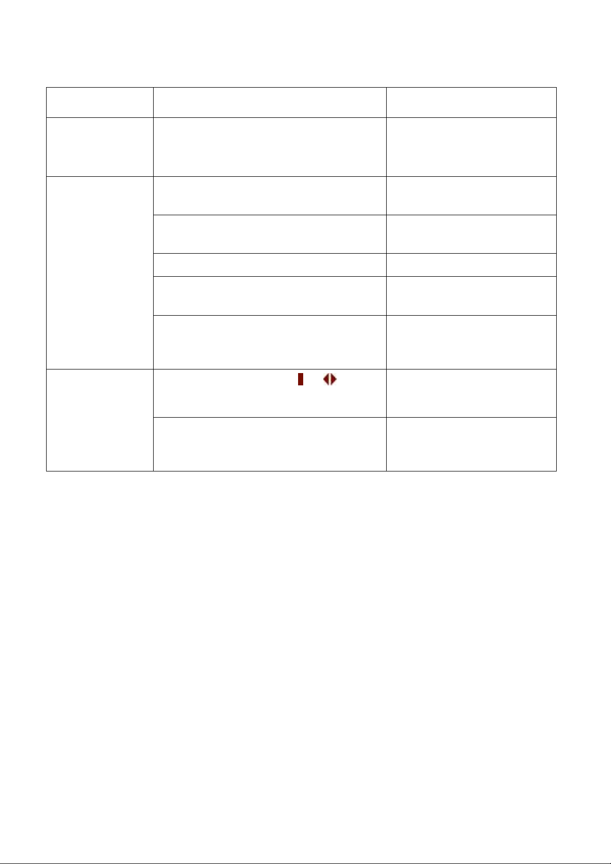
Abnormal
Description & Checkpoint
Solution
(14) All LED in
the front panel
light up.
CPU inserting error in 3A or 3R PCB
Insert the CPU into correct
socket.
(15)
Communication
interface is not
working
properly.
Communication cables are connected
improperly.
Correct the wiring.
Communication software is not
installed successfully.
Reinstall the software.
Communication port setup error.
Correct the setup.
CPU inserting error in 3R PCB.
Insert the CPU into right
socket.
If the abnormal cannot be corrected
after the solution actions have been
taken.
Refer to PCB LED
Detecting Guide and check
the 3R PCB.
(16) The
inverter has
been turned on
but no action of
inverter.
The inverter switches of & are not
pressed simultaneously.
Try to press these two
buttons simultaneously
PCB Connection is not good.
Refer to PCB LED
Detecting Guide and check
the connection of 3W PCB.
6005-145 Rev. A
9-14
Page 100
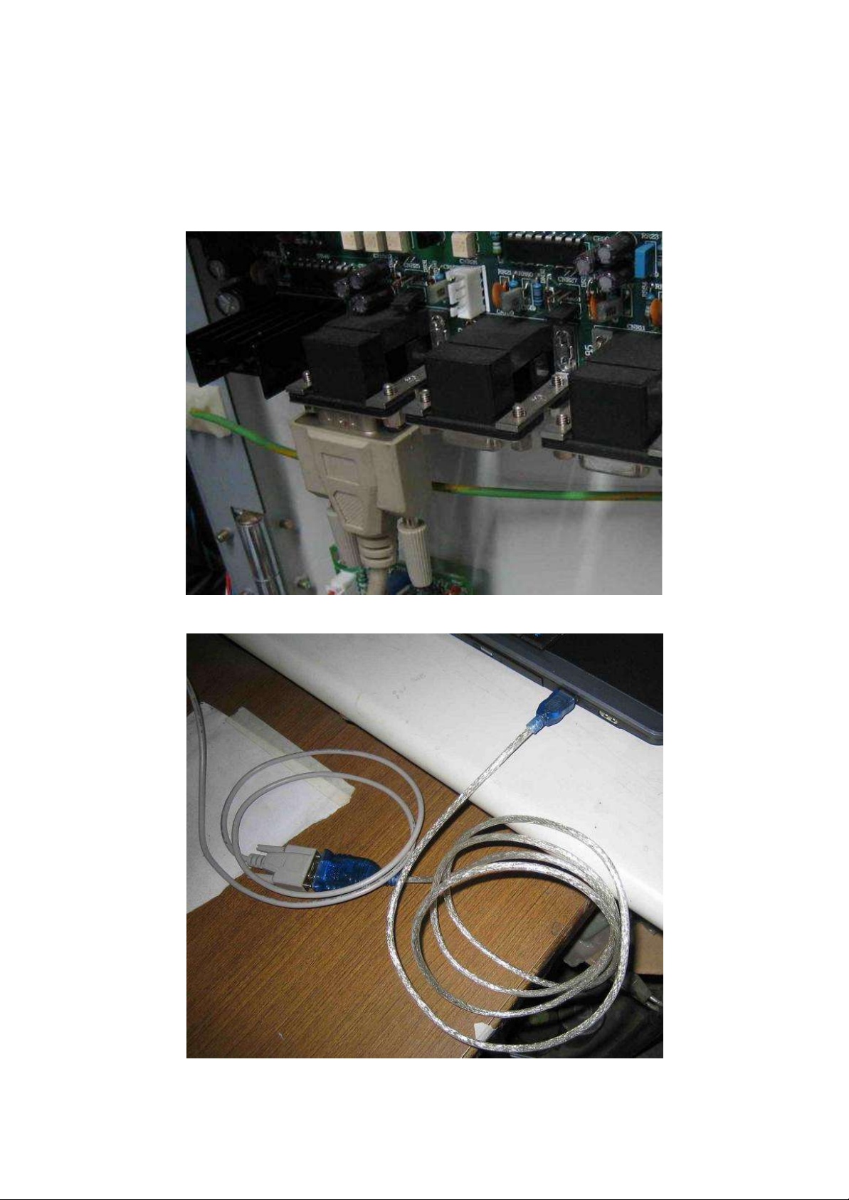
Appendix A
Battery Exerciser setting
1. CONNECT THE DB9 WIRE FROM UPPER SOCKET OF CNR21 …
2. TO USB OF LAPTOP VIA A RS-232 TO USB CONVERTER.
6005-145 Rev. A
9-15
 Loading...