

Page 1

-
Technical Publications
POWER-REG (1 and 3 Phase)
ULTRA-REG
PHASE STABILIZER
CONSTANT POWER 18
Operating Documentation
6002-032 Rev. H
Page 2

OnLine Power
Congratulations on selecting one of the fine products from OnLine Power, the Leader in Power Protection
Technology. Our wide product offering includes Uninterruptible Power Systems (UPS), Power Conditioners,
Automatic Voltage Regulators and Specialty Transformers (e.g. computer-grade, medical-grade). Since our
beginnings in 1975, OnLine Power has shipped thousands of these fine products around the world, to
discerning customers, for use on sensitive equipment and critical applications. Our customers, both new and
long-time, continue to enjoy security and peace of mind as they re alize what it means to ”Stay On Line with
OnLine Power”.
One of our goals is to make these manuals both comprehensive and easy to use. This new-format User’s
Manual is the result of ideas and inputs from customers who have taken an active inte rest in our continued
success. We invite constructive feedback on our products and documentation via fax, mail or telephone.
HEADQUARTERS FACTORY
OnLine Power, Inc OnLine Power, Inc.
5701 Smithway Street 5940 Triumph Street
Commerce, CA 90040 Commerce, CA 90040
SALES
Phone (800) 227-8899
Inside CA (323) 721-5017
FAX No. (323) 721-3929
MANUFACTURING
Phone (323) 720-4125
FAX No. (323) 889-6636
http://www.onlinepower.com
email: [email protected]
SERVICE
Phone (800) 797-7782
(PWR-SRVC)
FAX No. (323) 721-3929
6002-032 REV H a
Page 3

OnLine Power
OnLine Power, Inc.
Proprietary Reproduction or Distribution forbidden
NOTICE: THIS DOCUMENT CONTAINS PROPRIETARY INFORMATION
This document contains proprietary and confidential information of OnLine Power, Inc. (” OnLine Power”). In
consideration of the receipt of this document, the recipient agrees not to copy any of its contents, nor disclose
them to or allow them to be used by any person not currently a OnLine Power employee or an employee of the
recipient having a need to know, without the express written consent of OnLine Po wer, and further agrees to
surrender this document to OnLine Power when the reason for its receipt has terminated.
6002-032 REV H b
Page 4
OnLine Power
SAFETY
Safety precautions are important when operating or servicing electrical equipment. The following symbols are
used extensively throughout this manual. Always heed these precautions since they are essential to the safe
operation and servicing of this product.
DANGER!!
THIS DANGER SYMBOL IDENTIFIES A CONDITION OR ACTION WHICH
WILL RESULT IN SEVER INJURY OR DEATH TO AN INDIVIDUAL OR SEVER
DAMAGE TO EQUIPMENT OR OTHER PROPERTY.
CAUTION
This Caution symbol identifies a condition or action which may result in minor injury to an
individual or minor damage to the equipment or other property.
This unit was designed for specific applications. It should not be modified and/or used for any application other
than for that which it was designed. Optional equ ipment not described in the sales literature or this manual
should not be installed without first checking with the Service department. If you have any questions about this
unit’s application call the Service department at the number shown on the previous page.
SAVE THESE INSTRUCTIONS
This technical manual contains important instructions for each model that should be followed during installation
and maintenance of the UPS.
6002-032 REV H c
Page 5

OnLine Power
SAVE THESE INSTRUCTIONS
IMPORTANT SAFEGUARDS
1. READ AND FOLLOW ALL SAFETY INSTRUCTIONS.
2. DO NOT USE OUTDOORS.
3. DO NOT MOUNT NEAR GAS OR ELEC TRIC HEATERS.
4. EQUIPMENT SHOULD BE MOUNTED IN LOCATIONS AND AT HEIGHTS
WHERE IT WILL NOT READILY BE SUBJECTED TO TAMPERING BY
UNAUTHORIZED PERSONNEL.
5. THE USE OF ACCESSORY EQUIPMENT NOT RECOMMENDED BY THE
MANUFACTURER MAY CAUSE AN UNSAFE CONDITION.
6. DO NOT USE THIS EQUIPMENT FOR OTHER THAN INTENDED USE.
6002-032 REV H d
Page 6

OnLine Power
TABLE OF CONTENTS
SECTION
PAGE
SECTION 1 - OPERATION 1-1
1-1 INTRODUCTION 1-1
1-1-1 Power-Reg and Ultra-Reg 1-2
1-1-2 Phase Stabilizer 1-3
1-1-3 Constant Power 18 1-4
1-2 BENEFITS 1-5
1-3 TRANSFORMER 1-5
1-4 PRODUCT FEATURES 1-5
1-4-1 Bypass Switch 1-12
1-4-2 Main Input Circuit Breaker (IMCB) 1-12
1-4-3 Power On Indicators 1-12
1-4-4 Input and Output Power Terminals 1-12
1-4-5 Input Filter 1-13
1-4-6 Output Filter 1-13
1-5 REGULATION COMPONENTS 1-14
1-6 STARTING THE UNIT 1-18
1-7 OPERATION 1-19
1-7-1 Normal Condition 1-19
1-7-2 Nonregulating Condition 1-19
SECTION 2 - PREINSTALLATION 2-1
2-1 LOCATION CONSIDERATIONS 2-1
2-2 FLOOR LOADING 2-5
2-3 CABLE ACCESS AND FLOOR LAYOUT 2-6
2-3-1 Cable Access 2-6
2-4 MOUNTING 2-9
SECTION 3 - INSTALLATION 3-1
3-1 INSTALLATION 3-1
3-1-1 Unpacking 3-1
3-1-2 Inspection 3-2
3-1-3 Input Cable Installation - Power-Reg, Ultra-Reg & Phase Stabilizer
100 - 400 kVA 3-2
3-1-4 Output Cable Installation - Power-Reg, Ultra-Reg and Phase Stabilizer
125 – 400 kVA 3-4
3-1-5 Input Cable Installation - Phase Stabilizer 15 - 100 kVA
and Constant Power 18 3-5
3-1-6 Output Cable Installa tion - Phase Stabilizer 15 - 100 kVA
and Constant Power 18 3-6
3-1-7 Startup - Power-Reg, Ultra-Reg and Phase Stabilizer (100 - 400 kVA) 3-7
3-1-8 Startup - Phase Stabilizer 15 - 100 kVA and Constant Power 18 3-8
3-1-9 Calibrate Control Logic Board 3-10
6002-032 REV H i
Page 7

OnLine Power
SECTION
PAGE
3-2 CONFIGURATION 3-13
3-3 RENEWAL PARTS, POWER-REG AND ULT RA-REG 3-14
3-3-1 Vendor Parts List, Power-Reg and Ultra-Reg 3-15
3-4 RENEWAL PARTS, SINGLE PHASE POWER-REG 3-17
3-4-1 Vendor Parts List, Single Phase Power-Reg 3-18
3-5 RENEWAL PARTS, PHASE STABILIZER (100 - 175 kVA) 3-19
3-5-1 Vendor Parts List, Phase Stabilizer (15 - 75 kVA) 3-20
3-5 RENEWAL PARTS, PHASE STABILIZER (15 – 100 Kva) 3-21
3-5-2 Vendor Parts List, Phase Stabilizer (100 - 400 kVA) 3-22
3-6 RENEWAL PARTS, CONSTANT POWER 18 3-23
3-6-1 Vendor Parts List, Constant Power 18 3-24
SECTION 4 - OPTIONS 4-1
4-1 INTRODUCTION 4-1
4-2 REMOTE EMERGENCY POWER OFF STATION, Constant Power 18 4-2
4-2-1 Installation for REPO 4-2
4-3 THERMAL REMOTE EMERGENCY POWER OFF STAT IO N 4-4
4-3-1 Installation for Thermal REPO 4-4
4-4 SURGE PROTECTION 4-6
4-5 MAIN INPUT CIRCUIT BREAKER, Phase Stabilizer (15 - 75 kVA) 4-6
4-5-1 Main Input Circuit Breaker with manual reset option 4-6
4-6 INPUT/OUTPUT FILTERING 4-7
4-7 POWER ISLAND 4-8
4-7-1 Features 4-8
4-7-2 Power Island Specifications 4-9
4-7-3 Preinstallation 4-10
4-7-4 Input/Output Interconnect Cable Installation 4-12
4-7-5 Output Cable Installation 4-13
4-8 OUTPUT METER 4-15
4-9 ALARM, MOV STATUS 4-16
APPENDIX A - SPECIFICATIONS A-1
APPENDIX B – SPECIAL OPTIONS/PROJECT B-1
B.1 POWER REGULATOR, 300KVA, 3 PHASE,
460V INOUT, 460Y/266V OUTPUT.
GLOSSARY G-1
6002-032 REV H ii
Page 8

OnLine Power
ILLUSTRATION PAGE
Section 1 OPERATIONS
1-1 REGULATED SYSTEM RESPONSE 1-1
1-2 POWER-REG, ULTRA-REG AND PHASE STABILIZER (100 - 400 KVA) 1-2
1-3 CONSTANT POWER 18 AND PHASE STABILIZER (15 - 100 KVA) FOR 480 VAC INPUT
(15 - 75 KVA) FOR 2 08 VAC INPUT 1-4
1-4 POWER-REG AND ULTRA-REG; 15 TO 150 KVA, 480 VAC INPUT
PHASE STABILIZER; 125 - 150 KVA, 480 VAC INPUT 1-6
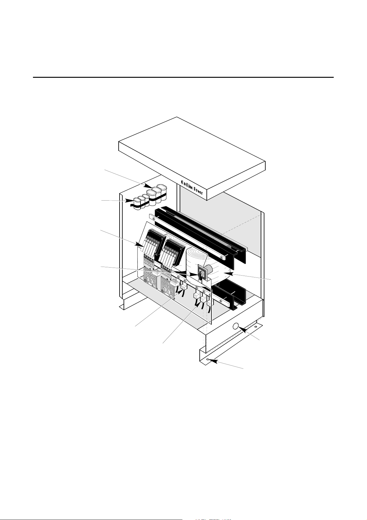
1-5 SINGLE PHASE POWER-REG (10 - 100 KVA) FEATURES 1-7
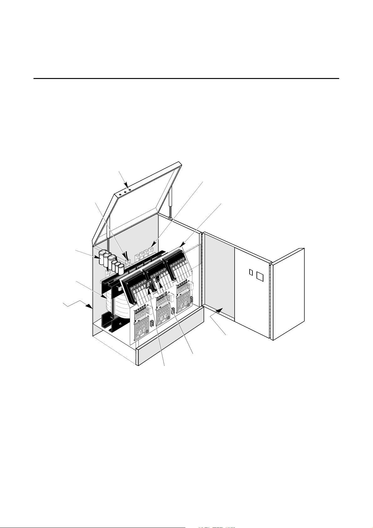
1-6 PHASE STABILIZER (15 - 75 KVA) AND CONSTANT POWER 18 FEATURES 1-8
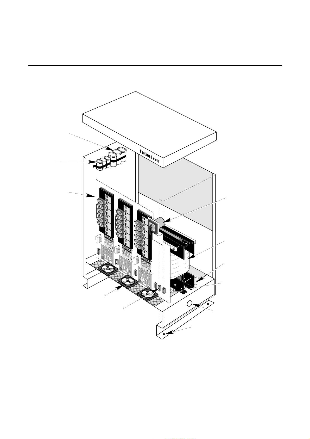
1-7 POWER-REG, ULTRA-REG; 175 KVA TO 400 KVA, 480 VAC INPUT
PHASE-STABILIZER; 125 KVA TO 400 KVA WITH 480 VAC INPUT 1-9
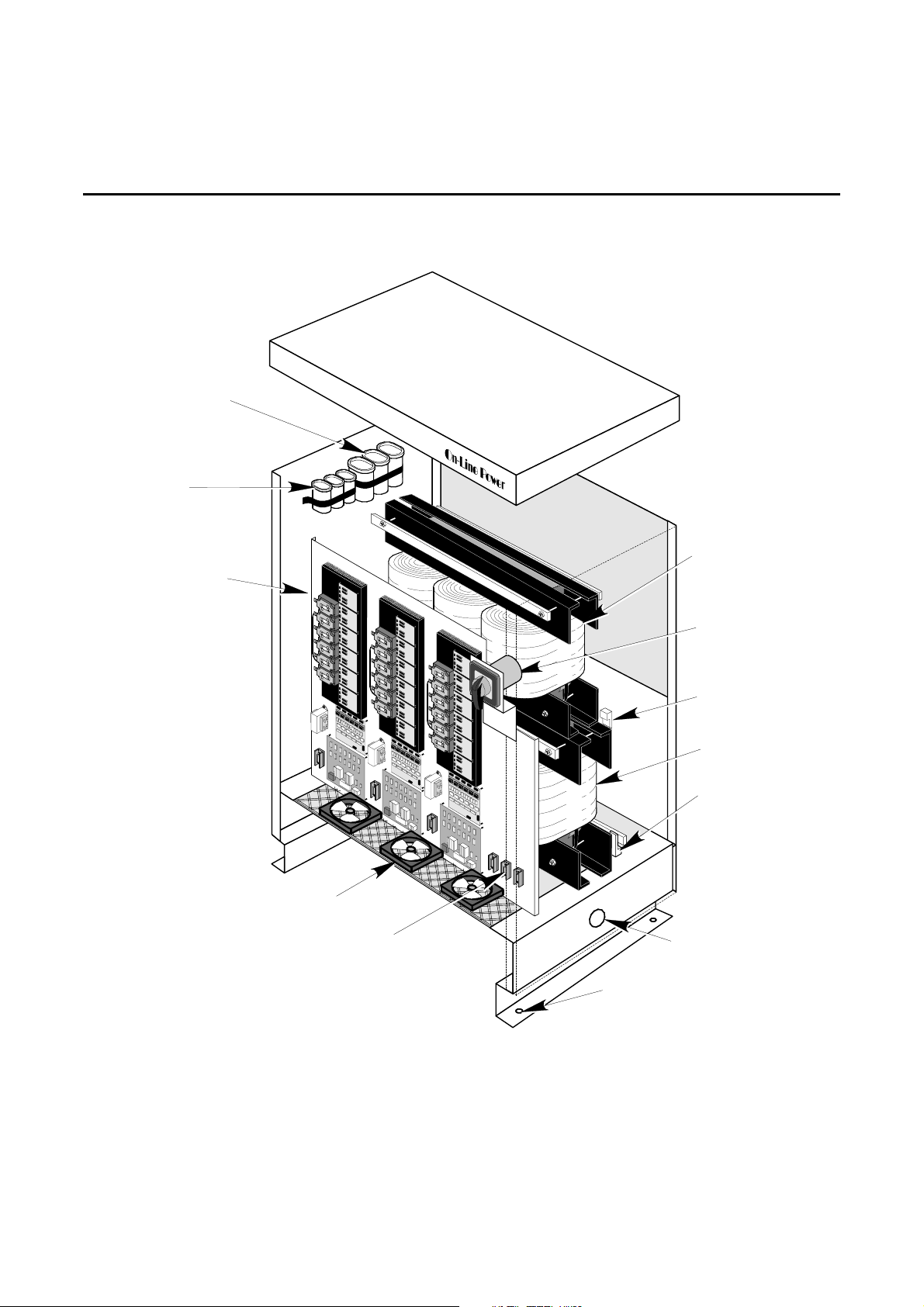
1-8 POWER-REG, ULTRA-REG, PHASE-STABILIZER; 175 KVA TO 400 KVA, 208 VAC INPUT 1-10
1-9 INPUT FILTER WIRING 1-12
1-10 OUTPUT FILTER WIRING 1-12
1-11 REGULATION PANEL ASSEMBLY LAYOUT 1-13
1-12 REGULATION PANEL ASSEMBLY LAYOUT 1-14
1-13 REGULATION BLOCK DIAGRAM 1-15
LIST OF ILLUSTRATIONS
Section 2 PREINSTALLATION
2-1 POWER-REG, ULTRA-REG AND PHASE STABILIZER (100 - 400 KVA) CABLE ACCESS 2-7
2-2 PHASE STABILIZER (15 - 75 KVA) AND CONSTANT POWER 18 CABLE ACCESS 2-7
2-3 PHASE STABILIZER (15 - 75 KVA) AND CP 18 CLEARANCES 2-8
2-4 POWER-REG, ULTRA-REG AND PHASE STABILIZER (100 - 400 KVA) CLEARANCES 2-9
Section 3 INSTALLATION
3-1 CONTROL LOGIC BOARD 3-12
3-2 SCR DRIVER BOARD 3-13
Section OPERATIONS
4-1 REPO BOX 4-2
4-2 REPO WIRING 4-3
4-3 THERMAL REPO WIRING 4-4
4-4 INPUT FILTER WIRING 4-7
4-5 OUTPUT FILTER WIRI NG 4-7
4-6 POWER ISLAND 4-8
4-7 POWER ISLAND FEATURES 4-9
4-8 POWER ISLAND CABLE ACCESS 4-10
4-9 POWER ISLAND FLOOR TILE CUTOUT 4-11
4-10 POWER ISLAND DIMENSIONS AND CLEARANCES 4-11
6002-032 REV H iii
Page 9

OnLine Power
LIST OF TABLES
TABLE
1-1 PRODUCT FEATURES 1-5
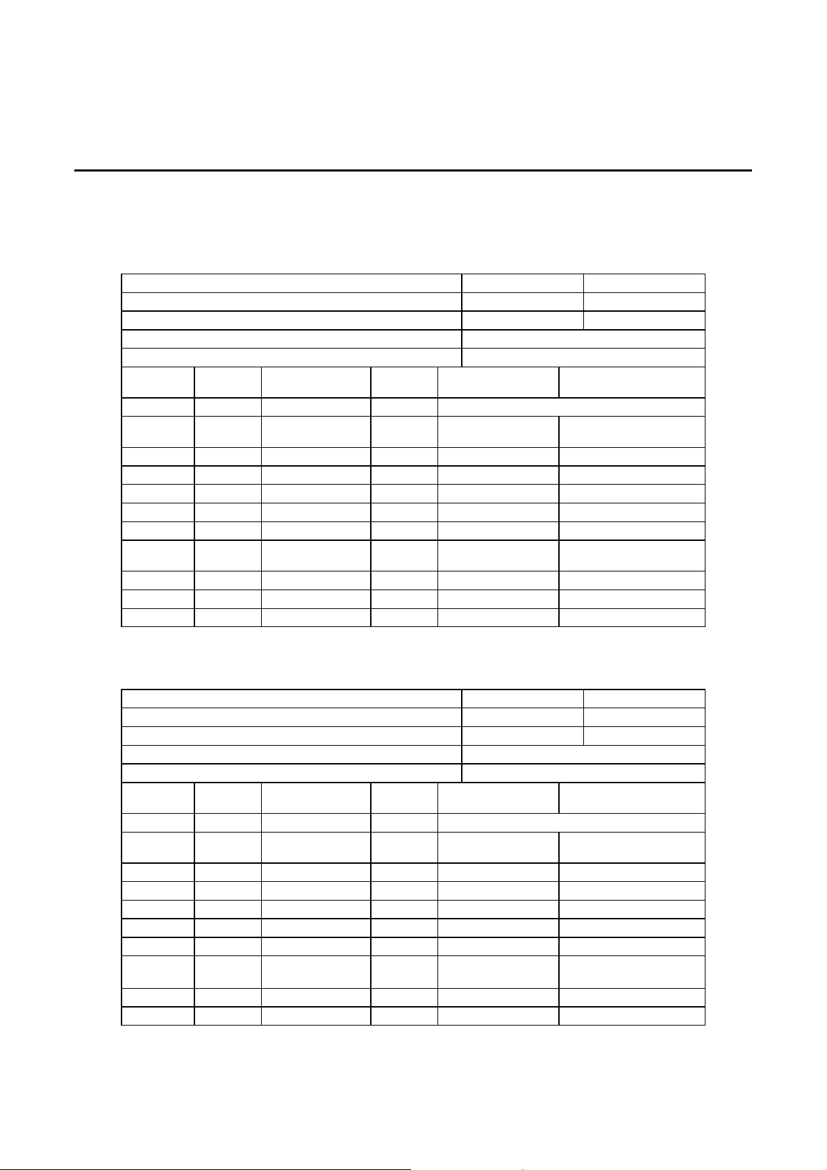
2-1 POWER-REG AND ULTRA-REG SITE PLANNING SPECIFICATIONS 2-2
2-2 SINGLE PHASE POWER-REG SITE PLANNING SPECIFICATIONS 2-3
2-3 CONSTANT POWER 18 SITE PLANNING SPECIFICATIONS 2-3
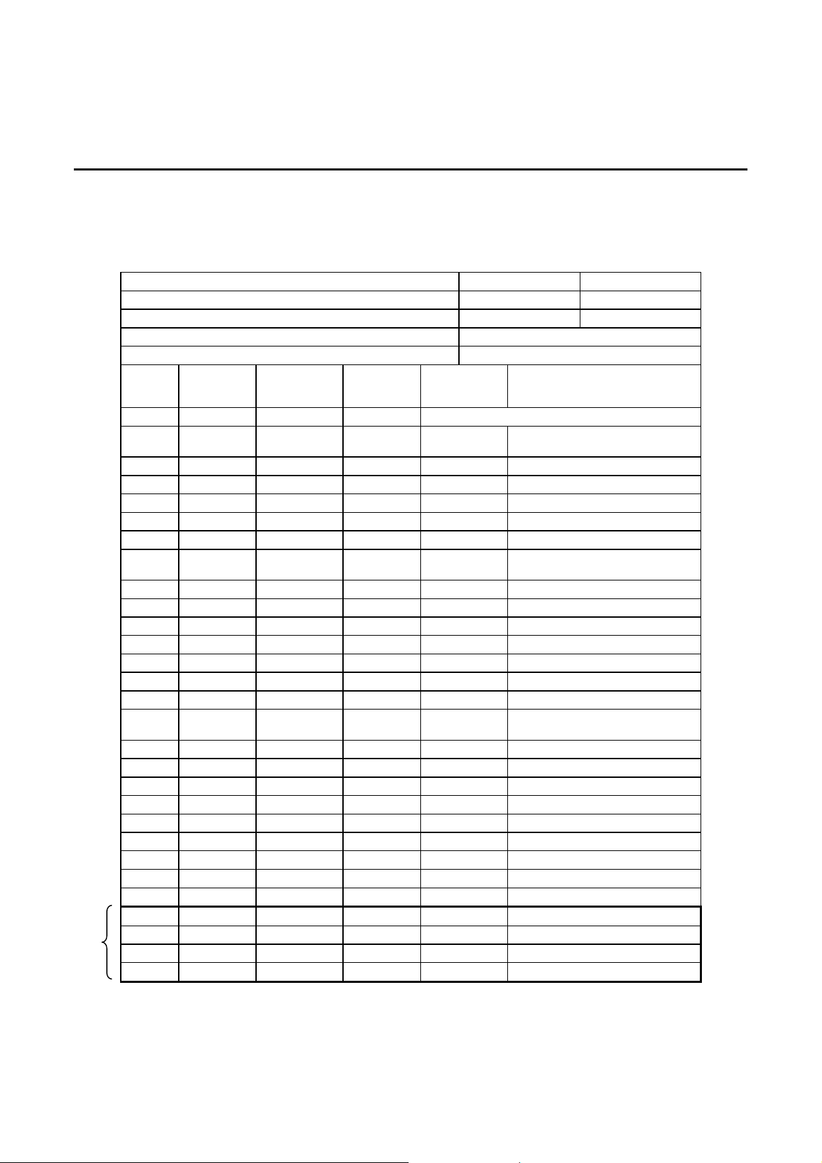
2-4 PHASE STABILIZER SITE PLANNING SPECIFICATIONS 2-4
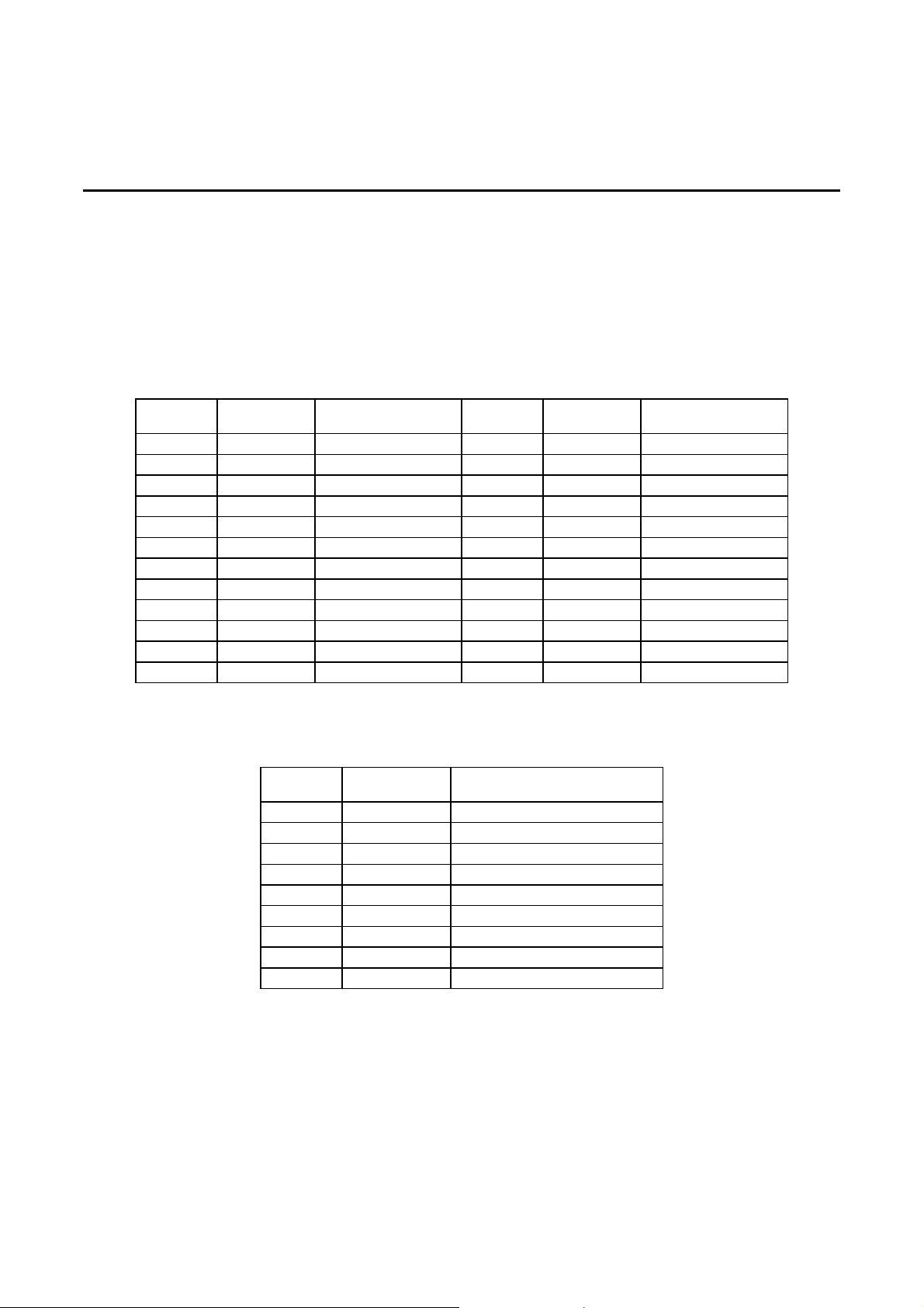
2-5 POWER-REG AND ULTRA-REG FLOOR LOADING 2-5
2-6 CONSTANT POWER 18 FLO OR LOADING 2-5
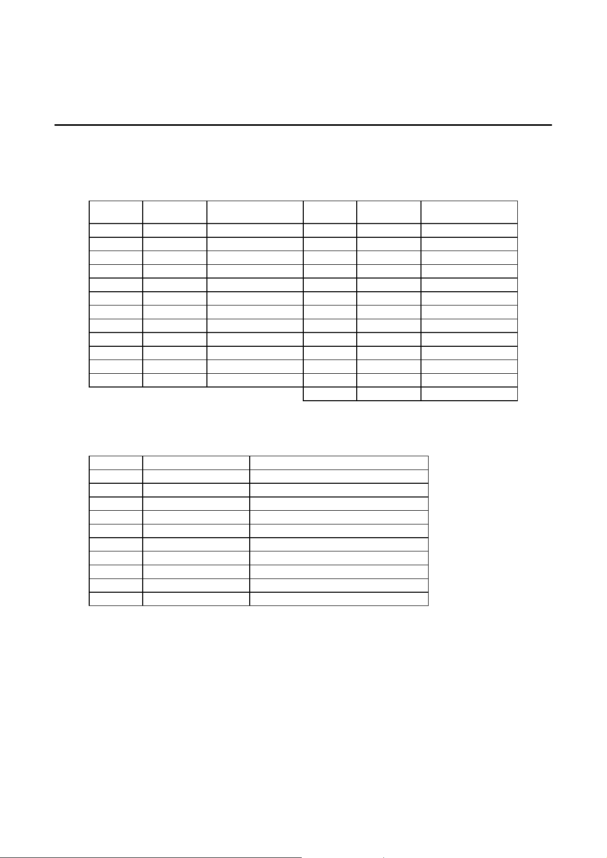
2-7 PHASE STABILIZER FLOOR LOADING 2-6
2-8 SINGLE PHASE POWER-REG FLOOR LOADING 2-6
3-1 POWER-REG AND ULTRA-REG CURRENT TRANSFORMERS 3-16
3-2 POWER-REG AND ULTRA-REG CURRENT TRANSFORMERS 3-18
3-3 PHASE STABILIZER (15 - 75 KVA) CURRENT TRANSFORMERS 3-20
3-4 PHASE STABILIZER (100 - 400 KVA) CURRENT TRANSFORMERS 3-22
3-5 CONSTANT POWER 18 CURRENT TRANSFORMERS 3-24
4-1 OPTIONS MATRIX 4-1
A-1 SPECIFICATIONS = POWER-REG AND ULTRA-REG A-1
A-2 SPECIFICATIONS = PHASE STABILIZER A-2
A-3 SPECIFICATIONS = CONSTANT POWER 18 1-3
PAGE
6002-032 REV H iv
Page 10
On-Line Power
SECTION 1 - OPERATION
1-1 INTRODUCTION
This manual provides installation, operation and maintenance information for the Power-Reg and Ultra-Reg
voltage regulator units as well as for the Constant Power 18 (CP 18) and Phase Stabilizer power conditioner
units. A detailed description of each product is provided in the following subsections.
All components used are of the highest quality and specifically selected to achieve the highest level of
performance. These units are UL listed and conform to National Electric Code (NEC) and Occupation al Safety
and Health Act (OSHA) standards.
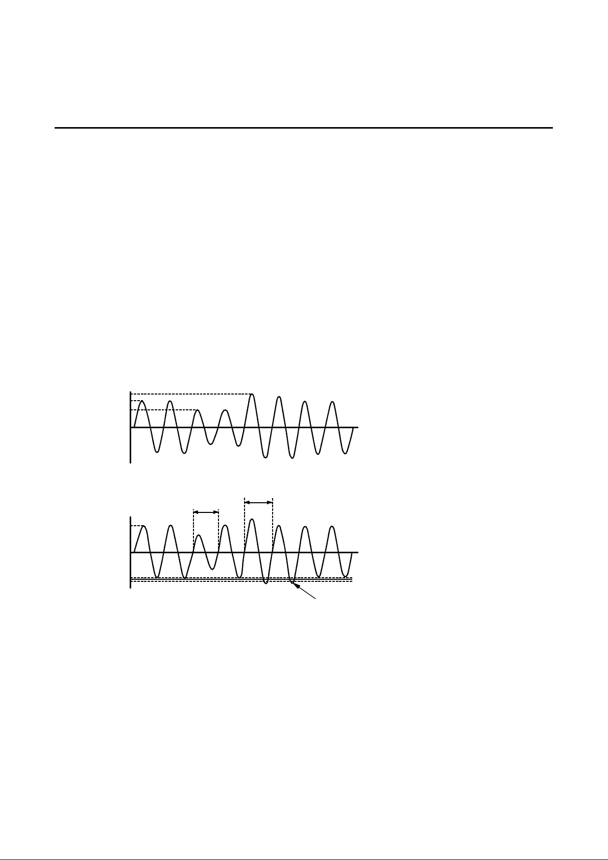
The Power-Reg, Ultra-Reg, Phase Stabilizer and CP 18 have tapped electronic voltage regulators. Six taps are
on each primary winding of the transformer. Each tap is controlled by a silicon-controlled rectifier (SCR) switch
and can become active at any time. Input line-to-line voltage and line current are monitored for each phase.
Peak voltage is compared with a desired reference. Depending on this comparison, the regulation logic
activates the proper SCR switch when the phase current becomes zero. This changes the primary-tosecondary turns ratio which corrects output voltage to the desired nominal. The correction process starts in
less than one cycle. See Illustration 1-1.
500
480
420
-480
480
-480
SURGE
SAG
0
INPUT
CORRECTED
CORRECTED
IN 1 CYCLE
0
IN 1 CYCLE
OUTPUT
REGULATED SYSTEM RESPONSE
ILLUSTRATION 1-1
POWER-REG, ULTRA-REG, CP18:
REGULATED TO +/- 3% OF NOMINAL TYPICAL
PHASE STABILIZER:
+
-
6002-032 REV H 1-1
Page 11
On-Line Power
1-1-1 Power-Reg and Ultra-Reg
The Power-Reg and Ultra-Reg are designed to provide the reliable, high-quality power necessary to meet the
needs of today’s sensitive electronics.
These three-phase, 60 Hertz, self-contained, modular units provide isolation and regulation of AC power. The
zero-current tap switching voltage regulation circuitry automatically adjusts for an input voltage range between
+10% surge and -26% sag about the nominal rated voltage with an output voltage range of ± 3% typical to ± 4%
maximum. Each phase is regulated independently. And also single phase, 60Hz, self contained units are
available.
The Power-Reg and Ultra-Reg are available in input voltages of 208 or 480 VAC and output voltages of
208Y/120 and 480Y/277 VAC. These units are available in sizes ranging from 15 kVA to 400 kVA . The specific
rating information for your unit is provided on the label plate located on the front panel. Refer to Appendix A.
The Power-Reg and Ultra-Reg unit is shown in Illustration 1-2.
POWER-REG, ULTRA-REG AND PHASE STABILIZER (100 - 400 KVA)
WITH 208 VAC INPUT OR (125-300 KVA WITH 480 VAC INPUT
ILLUSTRATION 1-2
6002-032 REV H 1-2
Page 12
On-Line Power
1-1-2 Phase Stabilizer
The medical-grade Phase Stabilizer power conditioner is designed to provide the reliable, high-quality power
necessary to suit the needs of today’s sensitive medical devices.
This three-phase, 60 Hertz, self-contained, modular unit provides isolation and regulation of AC power. T he
zero-current tap switching voltage regulation circuitry automatically ad justs for an input voltage range between
+8% surge and -10% sag about the nominal rated voltage with an output voltage range of ± 1.5% typical to ±
2% maximum. Each phase is regulated independently.
The Phase Stabilizer is available in input voltages of 208 or 480 VAC and output voltages of 208Y/120 and
480Y/277 VAC. This unit is available in sizes ranging from 15 kVA to 400 kVA. The specific rating information
for your unit is provided on the label plate located on the front panel. Refer to Appendix A.
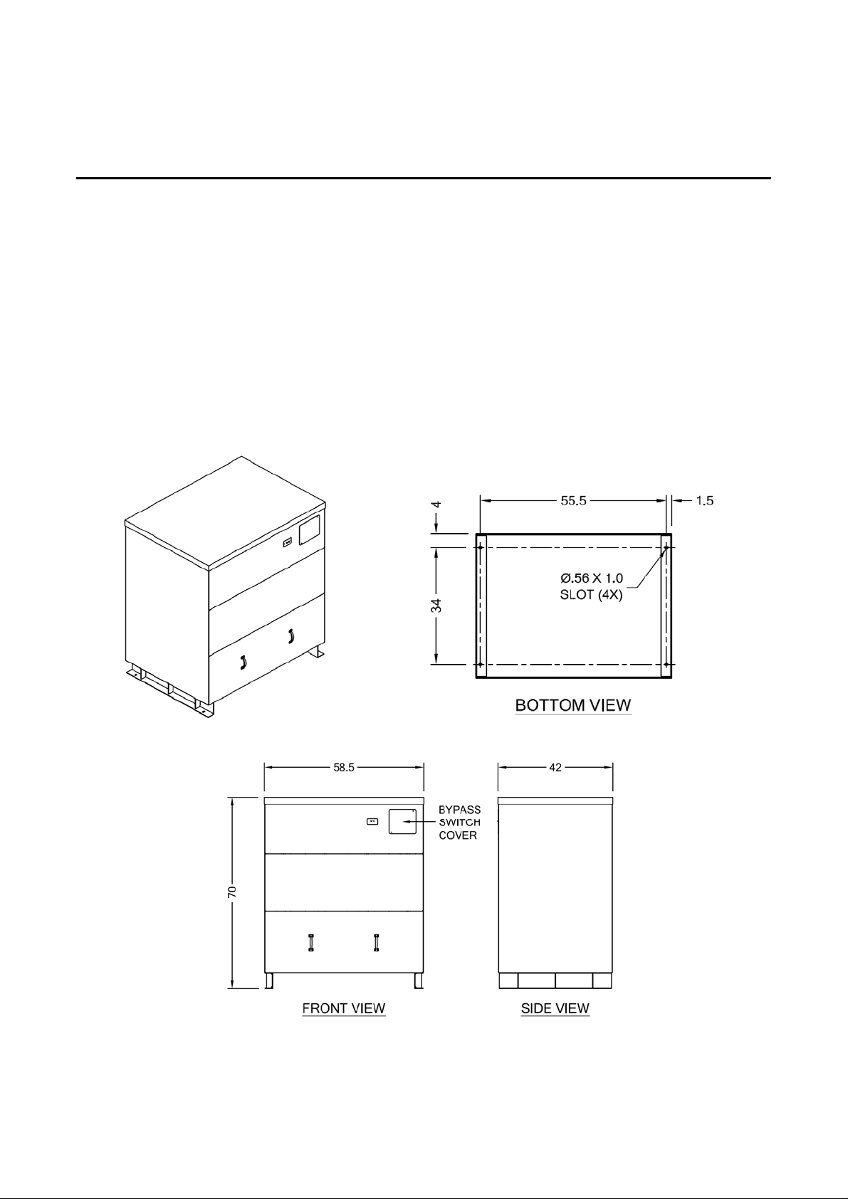
The 15 to 100 kVA Phase Stabilizer with 480 VAC or the 15-75 kVA with 208 VAC is shown in Illustration 1-3.
The 125 to 400 kVA Phase Stabilizer with 480 VAC input or the 100-400 kVA with 208 VAC input is shown in
Illustration 1-2.
ILLUSTRATION 1-2-A
6002-032 REV H 1-3
Page 13
On-Line Power
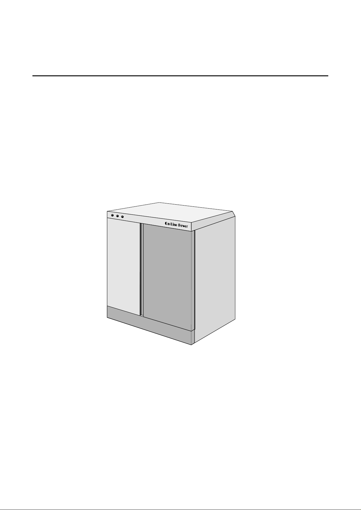
1-1-3 Constant Power 18
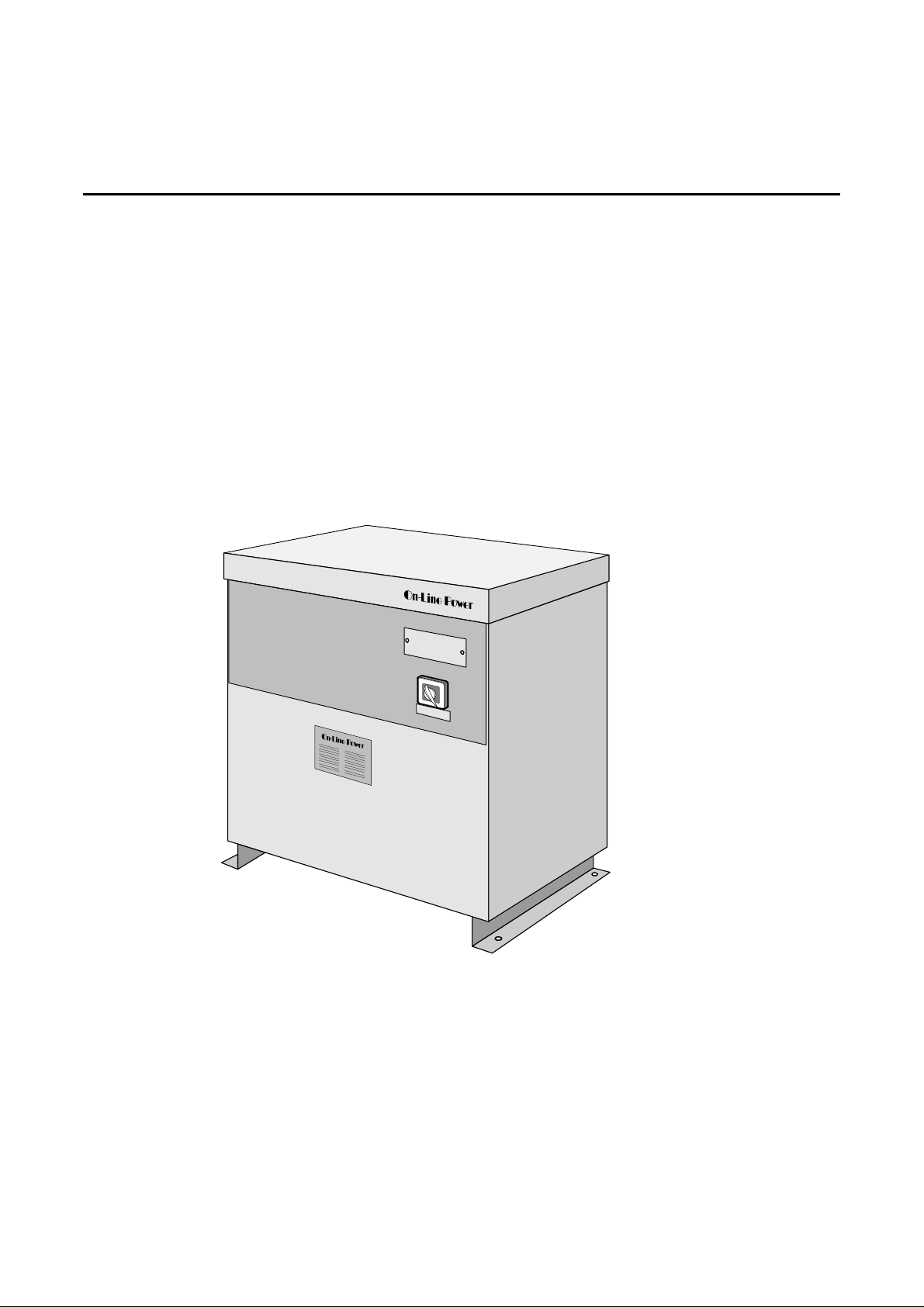
The Constant Power 18 is designed to provide the reliable, high-quality power necessary to suit the nee ds of
today’s sensitive electronics.
This three-phase, 60 Hertz, self-contained, modular unit provides isolation, shielding and regulation of AC
power. The zero-current tap switching voltage regulation circuitry automatically adjusts for an input voltage
range between +10% surge and -26% sag about the nominal rated voltag e with an output voltage range of ±
3% typical to ± 4% maximum. Each phase is regulated independently.
The Constant Power 18 is available in input voltages of 208 or 480 VAC and output voltages of 208Y/120 and
480Y/277 VAC. These units are available in 15, 30, 50, 75, and 100 kVA capacities. The specific rating
information for your unit is provided on the label plate located inside small front door. Refer to Appendix A-3.
The Constant Power 18 is shown in Illustration 1-3.
CONSTANT POWER 18 AND PHASE STABILIZER (15 - 100 KVA) FOR 480 VAC INPUT
(15 - 75 KVA) FOR 208 VAC INPUT
ILLUSTRATION 1-3
6002-032 REV H 1-4
Page 14
On-Line Power
1-2 BENEFITS
The Power-Reg, Ultra-Reg, Phase Stabilizer and CP 18 protect electronic equipment from an overvoltage
condition during line power surges and an undervoltage condition during sags. In addition, the unit protects
equipment load by attenuating transients present on utility power lines. overvoltage, overcurrent, and transient
conditions stress electronic components and decrease system reliability.
In medical applications, voltage fluctuations affect the image quality of imaging systems. Artifacts are
introduced under sag conditions. Regulating power maintains image quality, resulting in more consistent
images.
1-3 TRANSFORMER
The transformer contained in the unit is designed for convection cooling by means of free circulation of air
through the bottom, front and back of the unit. Maximum ambient temperatures should not exceed 104°F
(40°C). The transformer contains built-in thermal sensors which monitor internal temperatures. In models with
a Input Main Circuit breaker (IMCB), the thermal sensors send a shunt trip signal to the IMCB in the event of an
over temperature condition.
1-4 PRODUCT FEATURES
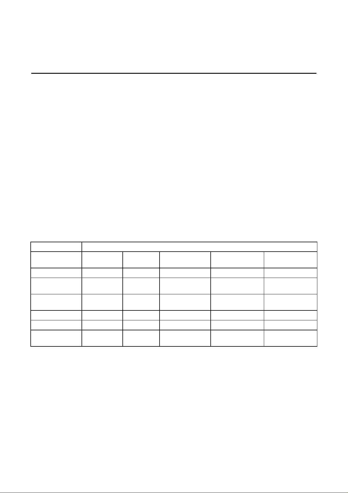
Sections 1-4 and 1-5 describe the features of the Power-Reg, Ultra-Reg, Phase Stabilizer and CP 18. Some
features described in Section 1-4 are stan dard on all m odels while ot her features ar e offered as options. Refer
to Table 1-1 to determine if the features described in this section are applicable to your unit. Refer to Section 4,
Options, for information on optional features.
TABLE 1-1
PRODUCT FEATURES
OPTION
Bypass Switch
Main Input
Power-Reg Ultra-Reg Constant
S S S S S
N N S O N
Circuit Breaker
Power On
N N S S N
Indicators
Input Filter
Output Filter
Input/Output
S S S S S
O O O S S
S S S S S
Power Terminals
TABLE KEY: S = Standard equipment, O = Available as an option, N = Not available for this model.
MODEL
Power 18
Phase Stabilizer
(15 - 75 kVA)
Phase Stabilizer
(100 - 400 kVA)
6002-032 REV H 1-5
Page 15
On-Line Power
1-4 PRODUCT FEATURES (continued)
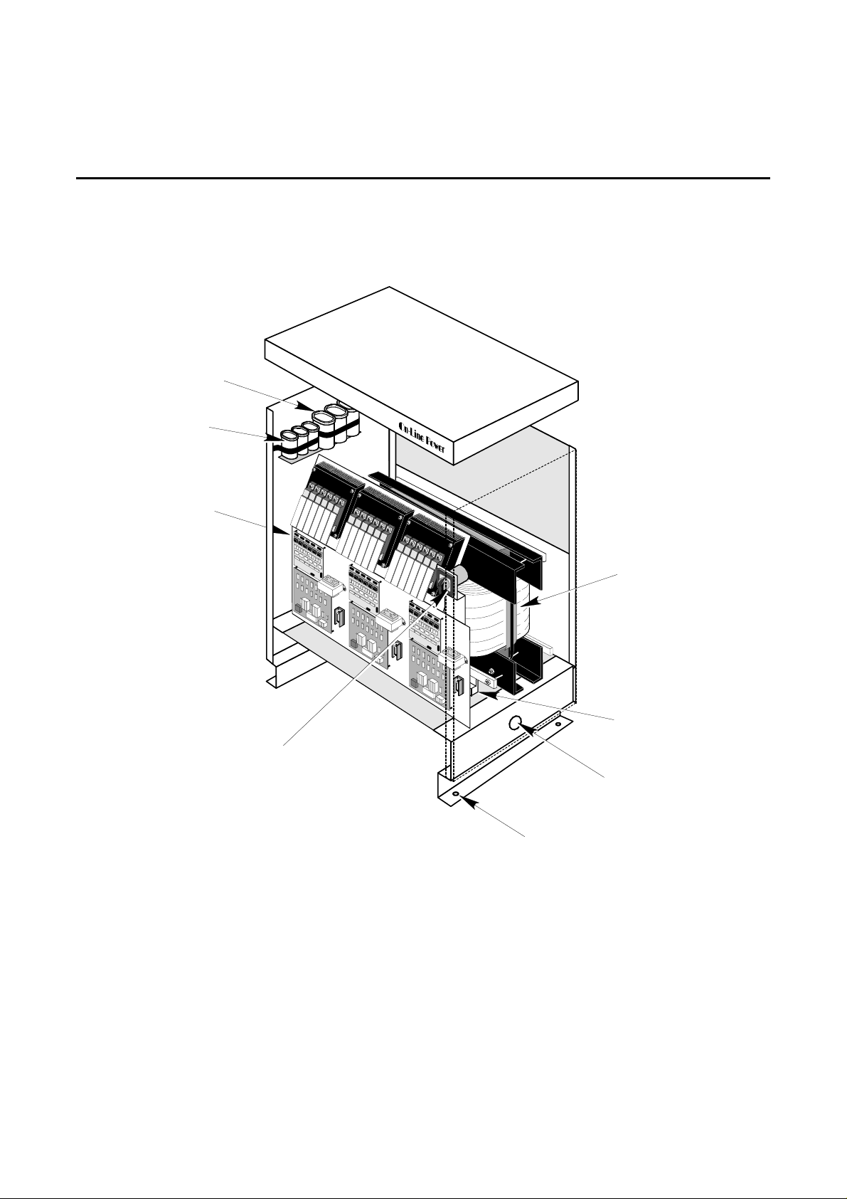
OUTPUT
FILTER
(Optional)
INPUT POWER
FILTER
REGULATION
ELECTRONIC PANEL:
- Heat Sinks
- SCR Snubber Boards
- SCR Power Blocks
- Reference Transformers
- SCR Driver Boards
- SCR Control Boards
- Fuses
BYPASS
SWITCH
MAIN POWER
TRANSFORMER
INPUT AND OUTPUT
POWER
TERMINAL
INPUT & OUTPUT
CABLE ACCESS
(BOTH SIDES)
POWER-REG AND ULTRA-REG; 15 TO 150 KVA, 480 VAC INPUT
PHASE STABILIZER; 125 - 150 KVA, 480 VAC INPUT
ILLUSTRATION 1-4
6002-032 REV H 1-6
9/16" Dia.
Mounting Holes
Page 16
On-Line Power
1-4 PRODU CT FEATUR ES (CONTINUED)
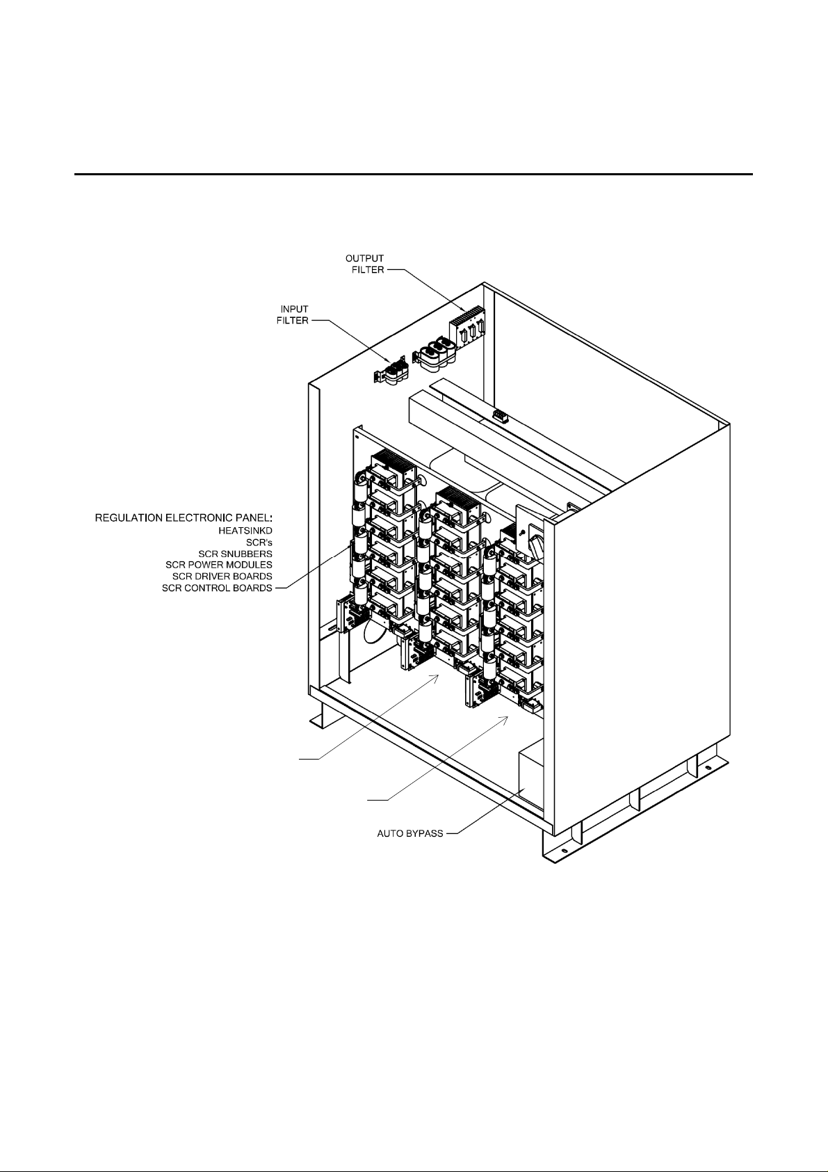
MAIN OUTPUT
MAIN INPUT
PHASE STABILIZER; 200 - 400 KVA,
ILLUSTRATION 1-4-A
6002-032 REV H 1-7
Page 17
On-Line Power
1-4 PRODUCT FEATURES (continued)
OUTPUT
FILTER
(OPTIONAL)
INPUT
FILTER
REGULATION
ELECTRONIC
PANEL
BYPASS SWITCH
INPUT POWER
TERMINAL BLOCK
OUTPUT POWER
TERMINAL BLOCKS
SINGLE PHASE POWER-REG; 10 - 100 KVA,
MAIN OUTPUT
TRANSFORMER
600V input
120/240V output
INPUT & OUTPUT
CABLE ACCESS
3/8" Dia. Mounting Holes
ILLUSTRATION 1-5
6002-032 REV H 1-8
Page 18
On-Line Power
1-4 PRODUCT FEATURES (continued)
POWER ON
INDICATORS
INPUT POWER
TERMINALS
INPUT/OUTPUT
FILTER
OUTPUT POWER
TERMINALS
REGULATION
ELECTRONIC PANEL:
- Heat Sinks
- SCR Snubber Boards
- SCR Power Blocks
- Reference Transformers
- SCR Driver Boards
- SCR Control Boards
- Fuses
MAIN
TRANSFORMER
REAR
VENTILATION
FRONT
VENTILATION
MAIN INPUT
CIRCUIT BREAKER
BYPASS
SWITCH
PHASE STABILIZER (15 - 75 KVA) AND CONSTANT POWER 18 FEATURES
ILLUSTRATION 1-6
6002-032 REV H 1-9
Page 19
On-Line Power
1-4 PRODUCT FEATURES (continued)
OUTPUT
FILTER
INPUT
FILTER
EGULATION
LECTRONICS
ANEL
BYPASS
SWITCH
FANS for
Electronic
Cooling
FAN FUSE
9/16" Dia.
Mounting Holes
POWER-REG, ULTRA-REG; 175 KVA TO 300 KVA, 480 VAC INPUT
PHASE-STABILIZER; 125 KVA TO 400 KVA WITH 480 VAC INPUT
ILLUSTRATION 1-7
MAIN POWER
TRANSFORMER
OUTPUT POWER
TERMINALS
INPUT POWER
TERMINALS
INPUT & OUTPUT
CABLE ACCESS
(BOTH SIDES)
6002-032 REV H 1-10
Page 20
On-Line Power
1-4 PRODUCT FEATURES (continued)
OUTPUT
FILTER
INPUT
FILTER
REGULATION
ELECTRONIC
PANEL
FANS for
Electronic Cooling
FAN FUSE
INPUT AUTO
TRANSFORMER
BYPASS SWITCH
INPUT POWER
TERMINALS
MAIN POWER
TRANSFORMER
OUTPUT POWER
TERMINALS
INPUT & OUTPUT
CABLE ACCESS
(BOTH SIDES)
9/16" Dia.
Mounting Holes
POWER-REG, ULTRA-REG, PHASE-STABILIZER; 175 KVA TO 400 KVA, 208 VAC INPUT
ILLUSTRATION 1-8
6002-032 REV H 1-11
Page 21
On-Line Power
1-4-1 Bypass Switch
The bypass switch is located on the front panel. See Illustrations 1-4 thru 1-8. This switch bypasses voltage
regulation but maintains the functioning o f the voltage change/isolation transformer between input an d output.
In AUTO position line to-neutral voltages are regulated. In MAN (manual) position, regulation log ic is bypassed
and input power is applied to load via transformer without regulation. Select the MAN position if there is a
problem with regulation logic circuitry. Refer to Section 1-7-2, Nonregulating Condition for the procedure to
operate the unit in bypass mode.
CAUTION
The Bypass Switch must never be changed with the unit powered up.
1-4-2 Main Input Circuit Breaker (IMCB)
The MAIN INPUT CIRCUIT BREAKER (IMCB) located on the front pa nel o f the unit, is used to switch p o wer to
the unit ON and OFF. See Illustration 1-6.
The IMCB is shunt tripped by activation of a solenoid within the breaker when remote switches or thermal
switches in the main transformer sense an over temperature condition. If the IMCB is shunt tripped, refer to
Section NO TAG, Miscellaneous Problems for the reset procedure.
An optional undervoltage shunt-trip is available.
Be sure to observe ALL warnings and cautions when setting the IMCB to ON or OFF.
1-4-3 Power On Indicators
Power On Indicators are located on the front of the unit. See Illustration 1-6. There is one neon indicating light
for each of the three phases. If a phase is lost, the corresponding in dicator will extinguish indicating which
phase is not powered.
1-4-4 Input and Output Power Terminals
Input and Output power connections are made at the terminals located beneath the transformer except the
illustration 1-6 where the terminals are located above and to the rear of the main transformer. See Illustration
1-4. Terminals are labeled H1, H2, H3, or L1, L2, L3 for the input cable connections and X0, X1, X2, X3 for the
output cable connections.
6002-032 REV H 1-12
Page 22
On-Line Power
1-4-5 Input Filter
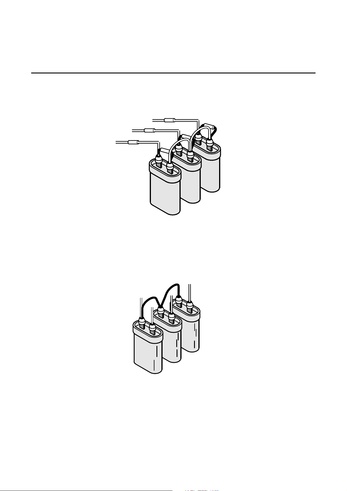
The Input filter is installed on the primary side of the transfor mer. The input filter consists of a r esistor/capacitor
network which acts as a large snubber circuit to eliminate high frequency impulses from entering the power
system. See Illustration 1-9.
R3
R6
R5
R4
C3
C2
(L1)
H1
(L2)
H2
R1
(L3)
H3
R2
C1
INPUT FILTER WIRING
ILLUSTRATION 1-9
1-4-6 Output Filter
The Output filter is installed on the transformer secondary. It consists of a capacito r network which prevents
noise from being fed back to the unit from noise generating loads. See Illustration 1-10. Output filters are
standard on the Phase Stabilizer and optional on other models.
X3
C4
X2
C6
C5
X0
X1
OUTPUT FILTER WIRING
ILLUSTRATION 1-10
6002-032 REV H 1-13
Page 23
On-Line Power
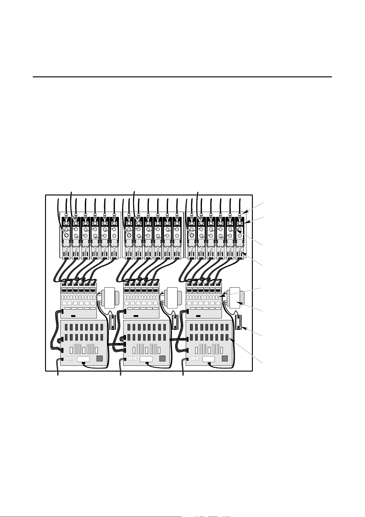
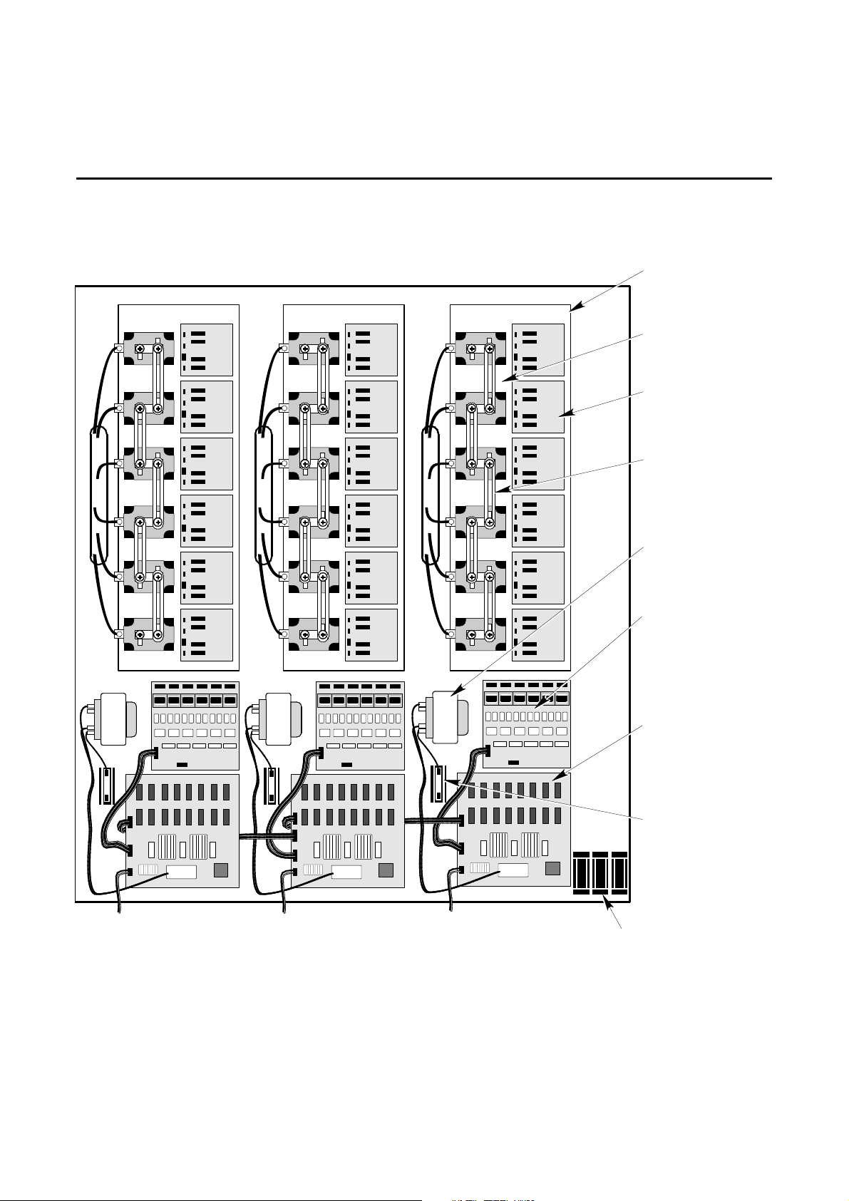
1-5 REGULATION COMPONENTS
Regulation is accomplished by solid-state electronics which control the tap switching function at the zerocurrent-crossing. Refer to Section NO TAG, THEORY OF OPERATION for more detail.
The regulation components are mounted on the regulation panel and can be seen by removing th e front panel.
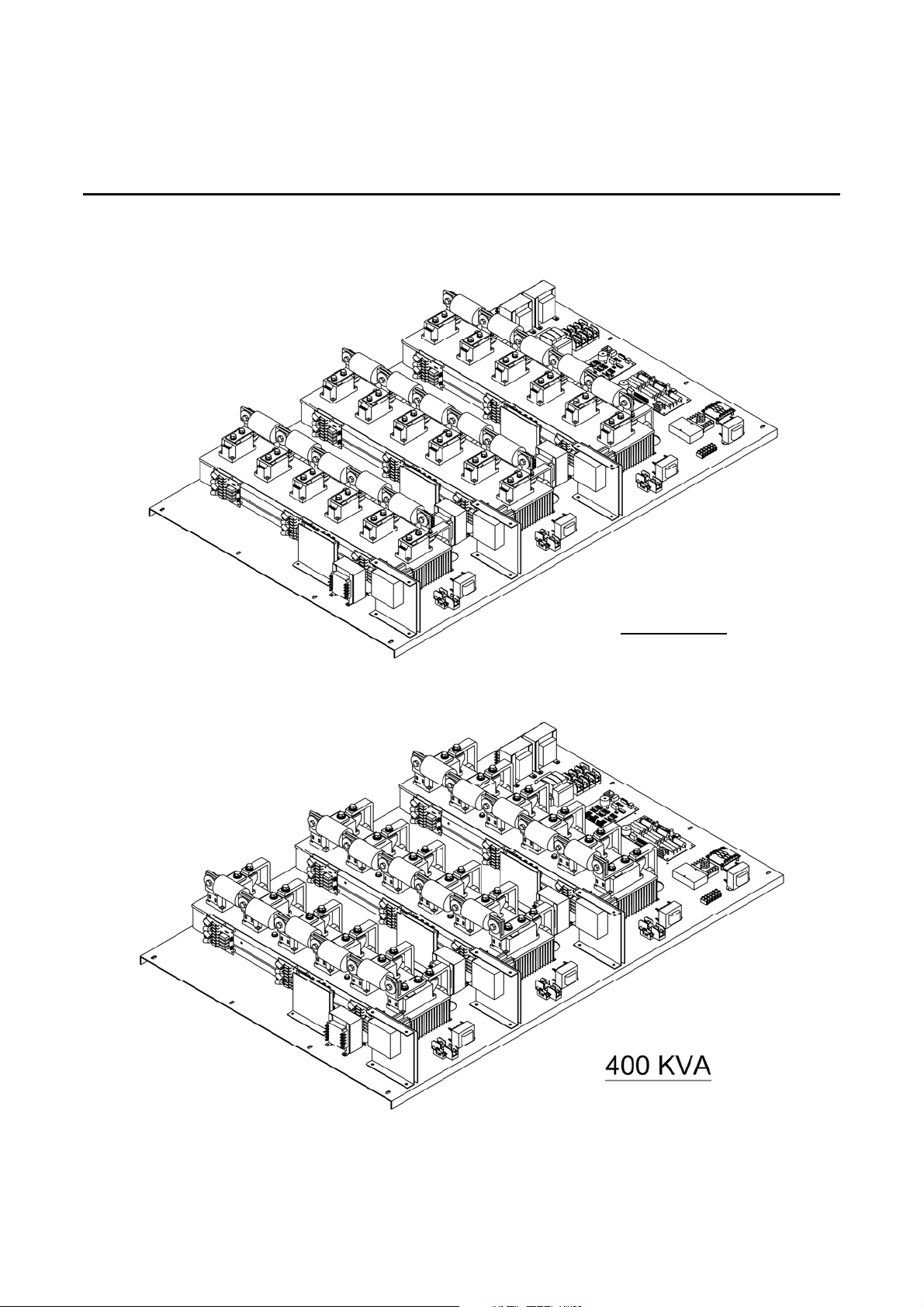
See Illustration 1-11 and 1-12. The regulation componen ts include 3 SCR Control logic boards, 3 SCR Driver
boards, 18 SCR/SCR Snubber board assemblies, 3 current transformers, 3 reference transformers, and 3
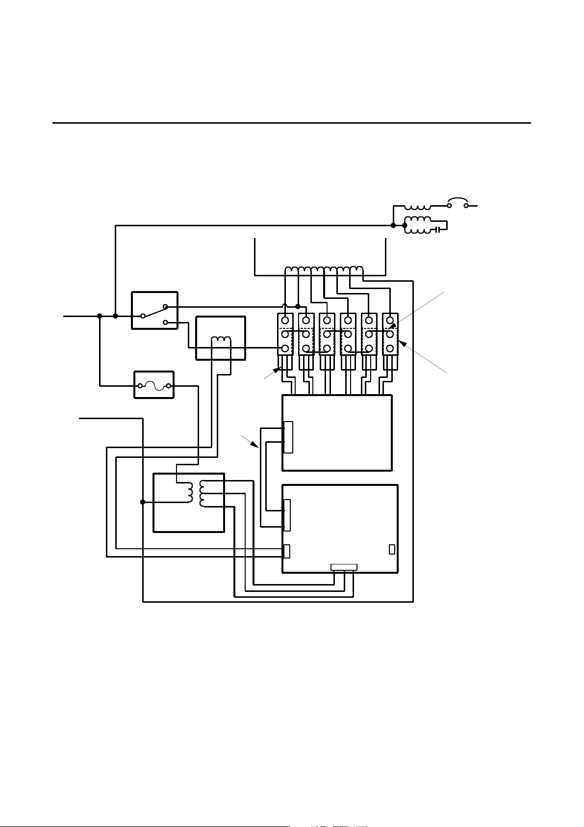
heatsinks. See Illustration 1-13 for a block diagram of the regulation panel components.
Each SCR Control logic board has seven LEDs. The first six LEDs indicate the active tap selection during
operation. LED 7 indicates power is applied to the board and is always lit during operation.
To Bypass To Bypass To Bypass
HEATSINK (3)
66554433221
To
Current
Transformer
66554433221
1
To
Current
Transformer
66554433221
1
To
Current
Transformer
1
SCR (18)
FUSELINK (15)
SCR SNUBBER
BOARD (18)
SCR DRIVER
BOARD (3)
REFERENCE
TRANSFORMER (3)
FUSES FOR
REF. TRANSFORMER (3)
(NOT ON ALL MODELS)
SCR CONTROL
LOGIC BOARD (3)
REGULATION PANEL ASSEMBLY LAYOUT (TYPICAL ONLY)
ILLUSTRATION 1-11
6002-032 REV H 1-14
Page 24
On-Line Power
1-5 REGULATION COMPONENTS (continued)
HEATSINK (3)
SCR (18)
SCR SNUBBER
BOARD (18)
FUSELINK (15)
REFERENCE
TRANSFORMER (3)
To
Current
Transformer
To
Current
Transformer
REGULATION PANEL ASSEMBLY LAYOUT (TYPICAL ONLY )
ILLUSTRATION 1-12
To
Current
Transformer
SCR DRIVER
BOARD (3)
SCR CONTROL
LOGIC BOARD (3)
FUSES FOR
REF. TRANSFORMER (3)
FUSES FOR
6002-032 REV H 1-15
Page 25
On-Line Power
1-5 REGULATION COMPONENTS (CONTINUED)
200 KVA
6002-032 REV H 1-16
Page 26
On-Line Power
1-5 REGULATION COMPONENTS (continued)
OUTPUT
INPUT
INPUT
BYPASS
SWITCH
3
4
1
FUSE
REFERENCE
TRANSFORMER
MANUAL
CURRENT
XFMR
4 WIRES
8 WIRES
AUTO
P1
P2
P1
SCR
DRIVER
BOARD
CONTROL
LOGIC
BOARD
P3
FUSEWIRE
(5 TIMES)
SCR/
SNUBBER
BOARD
(6 TIMES)
REGULATION BLOCK DIAGRAM
ILLUSTRATION 1-13
Note 1.
On Power-Reg, Ultra-Reg, and CP18, Tap 5 of the transformer is selected. On the Phase Stabilizer,
Tap 4 is selected.
6002-032 REV H 1-17
Page 27
On-Line Power
1-6 STARTING THE UNIT
This procedure is to be used only for starting the unit during the normal course of operation. Follow this
operating procedure any time the unit has been turned off in a non-emergency situation.
CAUTION
If this is the initial startup or if the unit has been moved, perform the
Startup procedure in Section 3-1-7 before applying power to the unit.
CAUTION
If the unit is connected to a Power Island modular distribution center, verify that all
panelboard output circuit breakers are OFF before turning on branch feeder circuit
breaker.
1. Verify that Bypass Switch is set to AUTO.
2. Verify that connected load is OFF.
3. Energize facility branch circuit breaker.
4. Open front door (Constant Power 18 only).
5. Set IMCB to ON (Constant Power 18 only).
6. Close front door.
7. Turn ON connected load.
6002-032 REV H 1-18
Page 28

On-Line Power
1-7 OPERATION
This unit is designed for unattended continuous operation. Units that have an IMCB can be switched ON and
OFF on a regular basis using the IMCB as a switch.
1-7-1 Normal Condition
When the unit is powered up and regulating, the power on indicating lights will be illuminated on the CP 18 only.
The normal operating condition of the unit is as follows:
1. Facility branch circuit breaker set to ON.
2. Bypass switch in AUTO position.
3. Input Main Circuit Breaker ON (if applicable).
4. Connected load set to ON.
D If Power Island connected, output panelboard circuit breakers ON (as required).
1-7-2 Nonregulating Condition
In case the regulating circuits fail to regulate, the unit can continue to operate in bypass mode (without
regulation) until regulation can be restored. F ollow the procedure listed below to operate the unit in bypass
mode.
Note
The following procedure is only for temporary operation. Voltage surge and sag protection is not
available for any load while the bypass switch is in manual mode (bypass switch is set to MAN).
1. Turn connected load OFF.
2. Set facility branch circuit breaker to OFF.
3. Set IMCB to OFF (if applicable).
4. Turn bypass switch from AUTO to MAN.
5. Set facility branch circuit breaker to ON.
6. Set IMCB to ON (if applicable).
7. Turn connected load ON.
8. Refer to manufacturer’s service personnel.
6002-032 REV H 1-19
Page 29

On-Line Power
SECTION 2 – PREINSTALLATION
2-1 LOCATION CONSIDERATIONS
OPERATING ENVIRONMENT. Provide an operating environment which meets the following conditions:
• AMBIENT TEMPERATURE 32° to 104° F
0° to 40° C
• RELATIVE HUMIDITY
Power-Reg, Ultra-Reg, Phase Stabilizer: 10% to 90% (noncondensing)
Constant Power 18: 5% to 95% (noncondensing)
POSITIONING. Position the unit so that the regulating electro nics are not obstructed by objects that could make
servicing the unit difficult. Allow minimum service access clearances as defined in Illustrations 2-3 and 2-4.
This unit is air cooled by convection. Do not block air flow from the front, rear, or bottom of the unit.
6002-032 REV H 2-1
Page 30
On-Line Power
NOMINAL INPUT VOLTAGE 208 480
INPUT VOLTAGE RANGE 154 – 229 355 – 528
MAXIMUM INPUT VOLTAGE 229 528
FREQUENCY (Hz) 60
AMBIENT TEMPERATURE °F (°C) 80 (26.7)
kVA SIZE INPUT
15 208 42 2040 400 (181) 32 X 26.5 X 17
30 208 83 4080 500 (227)
50 208 139 6800 700 (318) 40.5 X 31.5 X 22
75 208 208 10200 850 (386)
100 208 277.6 13600 1250 (567) 66 X 50.5 X 32 (168 X 128 X 81)
125 208 347 17000 1400 (635) 66 X 50.5 X 32 (168 X 128 X 81)
150 208 416 20400 1500 (680) 66 X 50.5 X 32 (168 X 128 X 81)
175 208 485.8 23800 1700 (771) 66 X 50.5 X 32
200 208 555 27200 2000 (907)
225 208 625 30600 2250 (1021)
250 208 694 34000 2450 (1111)
300 208 833 40800 2900 (1315)
VOLTAGE
480 18
480 36
480 60
480 90
480 120 1000 (454) 40.5 X 31.5 X 22 (103 X 80 X 56)
480 150 1100 (499) 51.5 X 40.5 X 26.5 (131 X 103 X 67)
480 180.4 1200 (544) 51.5 X 40.5 X 26.5 (131 X 103 X 67)
480 210.5 1400 (635)
480 240.6 1500 (680)
480 270.6 1600 (726)
480 300.8 1800 (817)
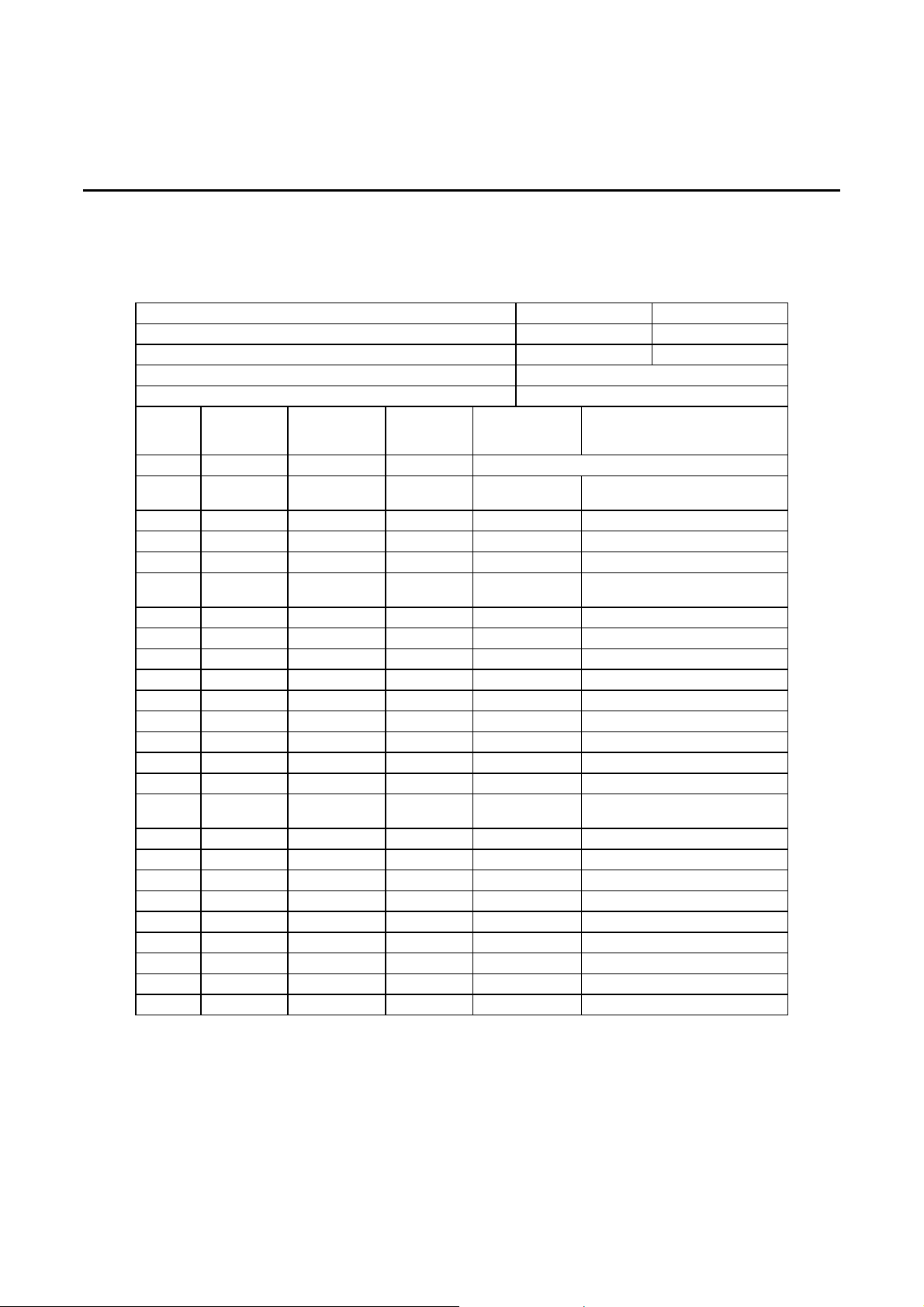
480 361 1950 (885)
TABLE 2-1
POWER-REG AND ULTRA-REG SITE PLANNING SPECIFICATIONS
NOMINAL
RATED
CURRENT
COOLING
BTU/hr
WEIGHT lbs (kg) SIZE H x W x D in. (cm)
WITHOUT PACKAGING
(107 X 67 X 43)
(103 X 80 X 56)
(168 X 128 X 107)
6002-032 REV H 2-2
Page 31
On-Line Power
NOMINAL INPUT VOLTAGE 208 480
INPUT VOLTAGE RANGE 154 – 229 355 – 528
MAXIMUM INPUT VOLTAGE 229 528
FREQUENCY (Hz) 60
AMBIENT TEMPERATURE °F (°C) 80 (26.7)
kVA SIZE INPUT
10 208 42 1364 350 (159) 32 X 26.5 X 17
20 208 42 2729 400 (181)
30 208 83 4080 500 (227)
50 208 139 6800 700 (318) 40.5 X 31.5 X 22
75 480 90 10200 850 (386)
100 480 120 13600 1000 (454)
VOLTAGE
480 18
480 18
480 36
480 60
TABLE 2-2
SINGLE PHASE POWER REG PLANNING SPECIFIC ATIONS
NOMINAL RATED
CURRENT
COOLING
BTU/hr
WEIGHT lbs (kg) SIZE H x W x D in. (cm)
WITHOUT PACKAGING
(81 X 67 X 43)
(103 X 80 X 56)
TABLE 2-3
CONSTANT POWER 18 SITE PLANNING SPECIFICATIONS
NOMINAL INPUT VOLTAGE 208 480
INPUT VOLTAGE RANGE 154 – 229 355 – 528
MAXIMUM INPUT VOLTAGE 229 528
FREQUENCY (Hz) 60
AMBIENT TEMPERATURE °F (°C) 80 (26.7)
kVA SIZE INPUT
15 208 42 2040 520 (236) 42 X 32 X 22
30 208 83 4080 570 (259)
50 208 139 6800 900 (408)
75 208 208 10200 1050 (476) 42 X 32 X 27
100 480 120 13600 1220 (549)
VOLTAGE
480 18
480 36
480 60
480 90
NOMINAL RATED
CURRENT
COOLING
BTU/hr
6002-032 REV H 2-3
WEIGHT lbs (kg) SIZE H x W x D in. (cm)
WITHOUT PACKAGING
(107 X 81 X 56)
(107 X 81 X 69)
Page 32
On-Line Power
NOMINAL INPUT VOLTAGE 208 480
INPUT VOLTAGE RANGE 187.2 – 225 432 – 518
MAXIMUM INPUT VOLTAGE 225 518
FREQUENCY (Hz) 60
AMBIENT TEMPERATURE °F (°C) 80 (26.7)
With
Auto-by
pass. CKT
New
design)
kVA SIZE INPUT
15 208 42 2040 400 (181) 42 X 32 X 22
30 208 83 4080 500 (227)
50 208 139 6800 700 (318)
75 208 208 10200 900 (408) 42 X 32 X 27
100 208 277.6 13600 1300 (590) 66 X 50.5 X 32 (168 X 127 X 81)
125 208 347 17000 1400 (635) 66 X 50.5 X 32 (168 X 128 X 81)
150 208 416 20400 1550 (703) 66 X 50.5 X 32 (168 X 128 X 81)
175 208 485.8 23800 1800 (817) 66 X 50.5 X 32
200 208 555 27200 2100 (953)
225 208 625 30600 2350 (1066)
250 208 694 34000 2550 (1157)
300 208 833 40800 3000 (1361)
200 480 210.5 27200 70x58.5x42 (177.8x148.6x106.7)
400 208 481.0 56800 70x58.5x42 (177.8x148.6x106.7)
VOLTAGE
TABLE 2-4
PHASE STABILIZER SITE PLANNING SPECIFICATIONS
NOMINAL
RATED
CURRENT
480 18
480 36
480 60
480 90
480 120 1150 (522) 42 X 32 X 22 (107 X 81 X 56)
480 150 1200 (544) 51.5 X 40.5 X 26.5 (131 X 103 X 67)
480 180.4 1250 (567) 51.5 X 40.5 X 26.5 (131 X 103 X 67)
480 210.5 1450 (658)
480 240.6 1550 (703)
480 270.6 1650 (748)
480 301 1900 (862)
480 361 2000 (907)
280
480
COOLING
BTU/hr
WEIGHT
lbs (kg)
SIZE H x W x D in. (cm)
WITHOUT PACKAGING
(107 X 81 X 56)
(107 X 81 X 69)
(168 X 128 X 81)
6002-032 REV H 2-4
Page 33
On-Line Power
2-2 FLOOR LOADING
Sizes and weights of units are listed in the following tables. Provide a floor with strength sufficient for loads
specified.
TABLE 2-5
POWER-REG AND ULTRA-REG FLOOR LOADING
kVA SIZE INPUT
15 208 128 (628) 150 208 129 (489
30 208 160 (788) 175 208 152 (563)
50 208 146 (710) 200 208 179 (662)
75 208 176 (862) 225 208 202 (746)
100 208 108 (414) 250 208 220 (811)
125 208 121 (464) 300 208 260 (960)
VOLTAGE
480 480 161 (788)
480 480 126 (464)
480 480 134 (497)
480 480 143 (530)
480 208 (1013) 480 161 (597)
480 148 (723) 480 175 (646)
FLOOR LOADING
lbs/sq ft (kg/sq m)
kVA SIZE INPUT
VOLTAGE
FLOOR LOADING
lbs/sq ft (kg/sq m)
TABLE 2-6
CONSTANT POWER 18 FLOOR LOADING
kVA SIZE INPUT
15 208 106 (520)
30 208 117 (571)
50 208 184 (899)
75 208 215 (1049)
100 480 250 (1221)
VOLTAGE
480
480
480
480
FLOOR LOADING
lbs/sq ft (kg/sq m)
6002-032 REV H 2-5
Page 34
On-Line Power
kVA SIZE INPUT
VOLTAGE
15 208 82 (399) 150 208 134 (513)
30 208 102 (500) 175 208 155 (597)
50 208 143 (701) 200 208 181 (696)
75 208 184 (899) 225 208 206 (778)
100 208 112 (431) 250 208 220 (845)
125 208 121 (464) 300 208 259 (994)
TABLE 2-7
PHASE STABILIZER FLOOR LOADING
FLOOR LOADING
lbs/sq ft (kg/sq m)
480 480 168 (822)
480 480 125 (480)
480 480 134 (513)
480 480 142 (546)
480 192 (934) 480 164 (629)
480 161 (788) 480 172 (662)
400 480 188 (724)
kVA SIZE INPUT
VOLTAGE
FLOOR LOADING
lbs/sq ft (kg/sq m)
TABLE 2-8
SINGLE PHASE POWER REG FLOOR LOADING
kVA SIZE INPUT VOLTAGE FLOOR LOADING lbs/sq ft (kg/sq m)
10 208 97 (35.3)
20 208 111 (40.2)
30 208 139 (50.4)
50 208 194 (71)
75 480 236 (86)
100 480 278 (101)
480
480
480
480
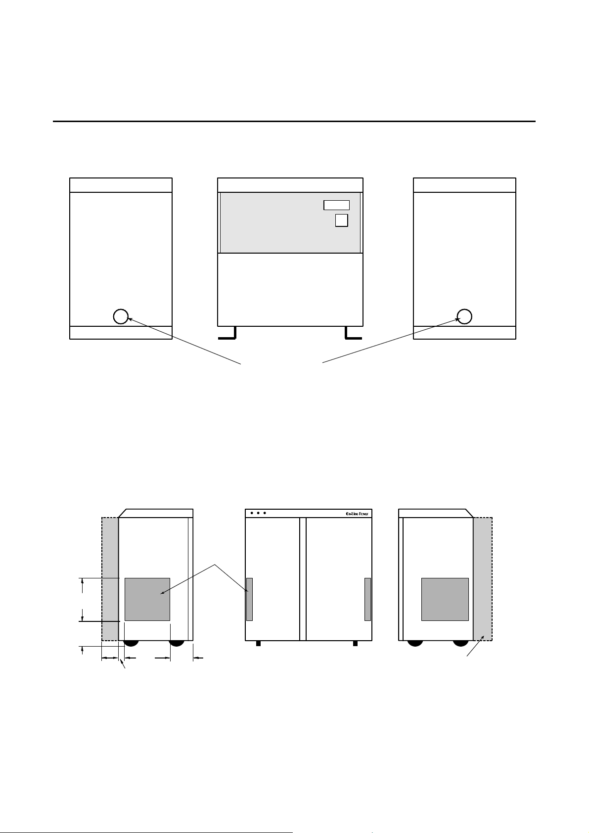
2-3 CABLE ACCESS AND FLOOR LAYOUT
2-3-1 Cable Access
Cable access to the Power-Reg, Ultra-Reg and Phase Stabilizer, sizes 100 to 400 kVA, is through a 4” diameter
hole in the right and left sides of the unit throu ght which the input and output cables can be passed. Cable
access to the Phaze Stabilizer, sizes 15 to 75 kVA, and the Constant Power 18 is through an open ing in the left
and right side of the unit. See Illustrations 2-1 and 2-2.
6002-032 REV H 2-6
Page 35
On-Line Power
LEFT SIDE VIEW RIGHT SIDE VIEW
FRONT VIEW
INPUT/OUTPUT
CABLE ENTRANCE
POWER-REG, ULTRA-REG AND PHASE STABILIZER (100 - 400 KVA) CABLE ACCESS
(REFER TO ILLUSTRATION 2-2-A FOR UNITS WITH AUTO BYPASS)
ILLUSTRATION 2-1
LEFT SIDE VIEW RIGHT SIDE VIEW
CABLE
ACCESS
OPENING
20
(50.8)
6
(15.2)
14
2
(5.1)
(35.6)
5
(12.7)
PHASE STABILIZER (15 - 75 KVA) WITH 208 VAC INPUT, (15-100 KVA) WITH 480 VAC INPUT AND CONSTANT POWER 18 CABLE
6
(15.2)
FRONT VIEW
for 75 kVA and 100 kVA
5" deep back screen 15 used
ACCESS
ILLUSTRATION 2-2
6002-032 REV H 2-7
Page 36
On-Line Power
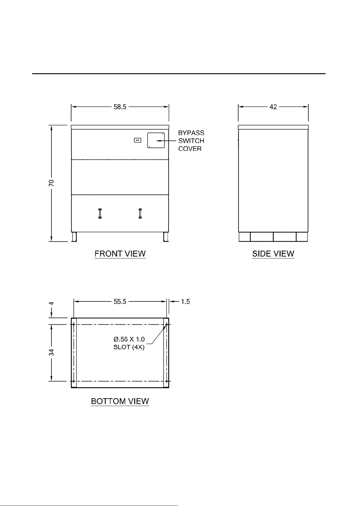
2-3-1-1 OUTLINE VIEW
200/ 400 KVA WITH AUTO-BYPASS CKT
illustration 2-2-A
6002-032 REV H 2-8
Page 37
On-Line Power
2-4 MOUNTING
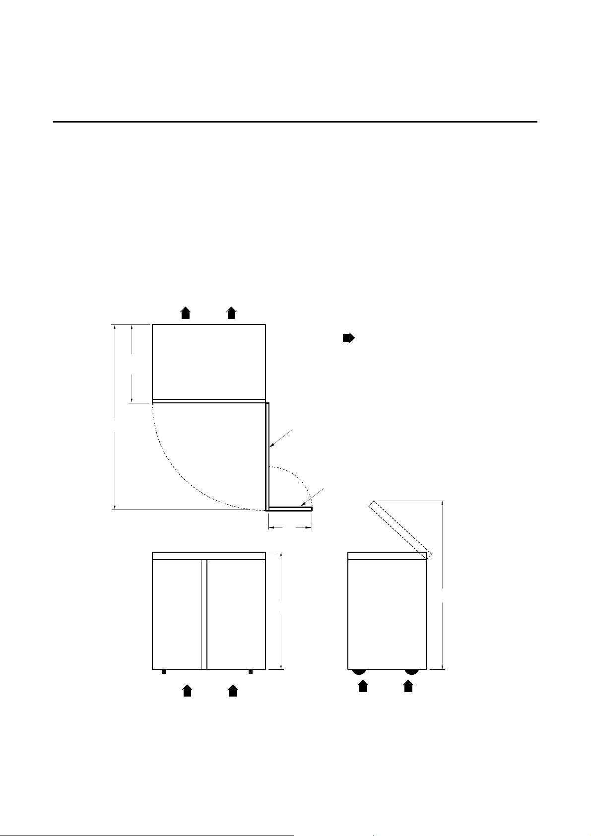
The Phase Stabilizer, sizes 15 to 75 kVA, and the CP 18 are equipped with leveling jacks to provide firm footing
when the unit is set in its permanent location. With the leveling jacks in place, the unit cannot roll on the
wheels. If local code requires the unit to be more firmly secured, mount the unit to the floor using angle
brackets. A seismic option is available to mechanically attach the unit to the floor.
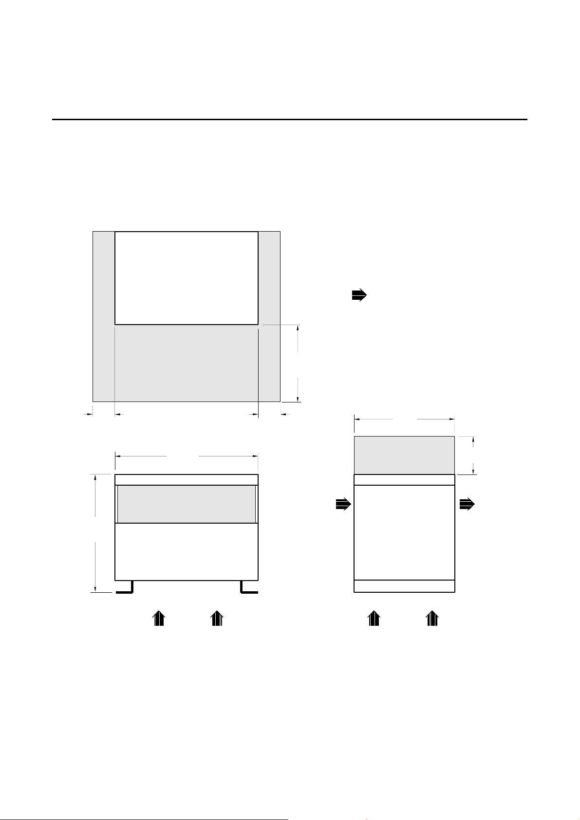
The Power-Reg, Ultra-Reg and Phaze Stabilizer, sizes 100 to 4 00 kVA, are equipped with angle-iron feet that
have four 9/16-inch diameter holes pre drilled for mounting. Units can be bolted to the floor using these
mounting holes. And single phase (10-100kVA) Power-Reg are also equipped with angle-iron, use same
mounting procedure as larger KVA units.
NOTE:
INDICATES AIR FLOW
22"(54)
TOP VIEW
ALL DIMENSIONS ARE
IN INCHES (CENTIMETERS)
54"(200)
FRONT PANEL
(HALF OPEN)
FRONT
DOOR
15"
(38)
42"(107)
FRONT VIEW
PHASE STABILIZER (15 - 75 KVA) AND CP 18 CLEARANCES
ILLUSTRATION 2-3
SIDE VIEW
59"(150)
6002-032 REV H 2-9
Page 38
On-Line Power
2-4 MOUNTING (continued)
14"
(35.6)
32"
(81.3)
TOP VIEW
SERVICE ACCESS
SPACE REQUIRED
26.5"
(67)
FRONT VIEW
14"
(35.6)
NOTE:
INDICATES AIR FLOW
ALL DIMENSIONS ARE
IN INCHES (CENTIMETERS)
38"
(96.5)
17"
(43)
14"(35.6)
SIDE VIEW
POWER-REG, ULTRA-REG AND PHASE STABILIZER (100 - 400 KVA) CLEARANCES
ILLUSTRATION 2-4
6002-032 REV H 2-10
Page 39
On-Line Power
2-4 MOUNTING (CONTINUED)
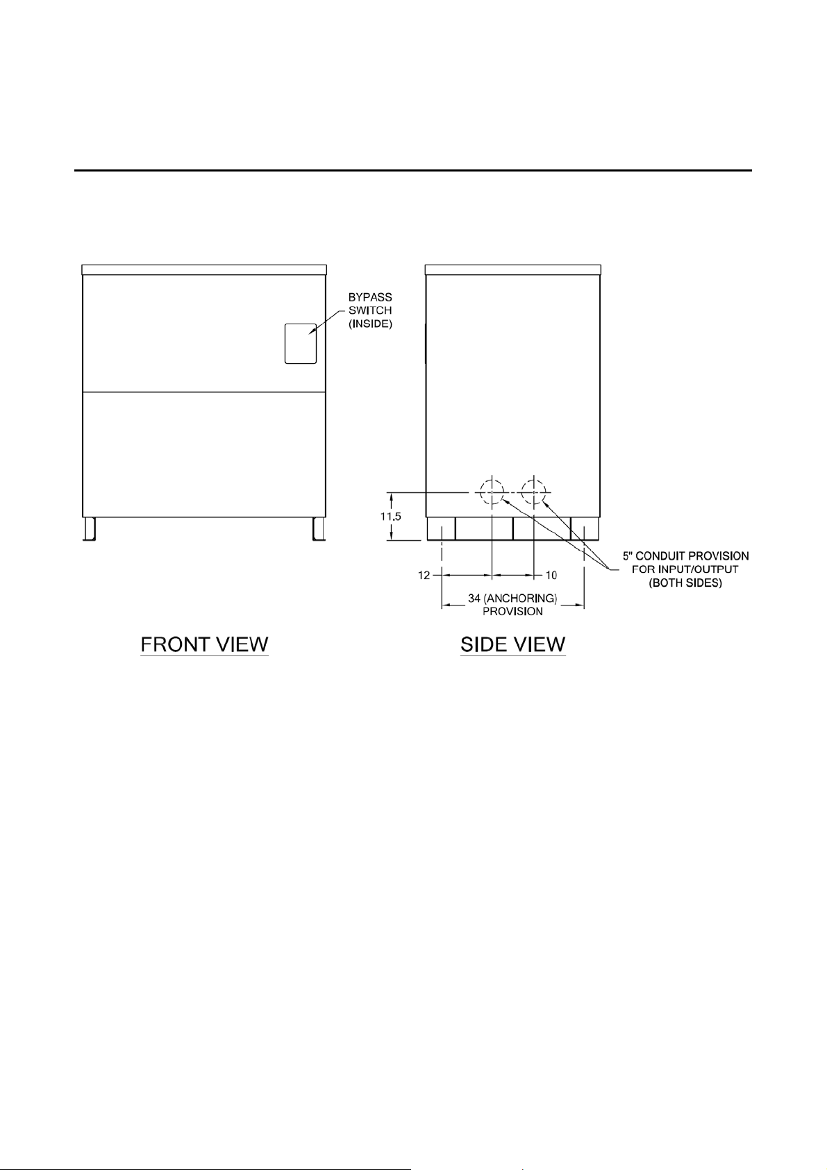
PHASE STABILIZER NEW (200 - 400 KVA) WITH AUTO-BYPASS CKT
ILLUSTRATION 2-4
6002-032 REV H 2-11
Page 40
OnLine Power
SECTION 3 - INSTALLATION
3-1 INSTALLATION
Install unit using the procedures in this section. Final insta llation must be in accordance with NEMA standa rds
and conform to local electrical codes as appropriate.
3-1-1 Unpacking
Unit is shipped on a pallet, secured with metal bands and can be handeled using a fork lift or pallet jack.
DANGER!!
CUT METAL BANDS CAREFULLY. THEY ARE UNDER TEN SION AND MAY
CAUSE INJURY.
1. Position the container away from walls or other obstructions.
2. Cut metal shipping bands.
3. Remove cardboard cover. Avoid puncturing the cardboard cover with sharp objects which may damage the
surface of the unit.
4. Remove the unit from the pallet.
• Power-Reg, Ultra-Reg and Phase Stabilizer (100- 400 kVA) can be removed using fork lift.
• CP 18 and Phase Stabilizer (15 - 75 kVA) come with integral casters and are packed with a wooden
ramp. Secure ramp from slipping and roll unit off pallet. Secure ramp to pallet before rolling unit down
ramp.
• Single phase Power-Reg (10-100KVA) can be removed using forklift.
5. Remove protective plastic film.
6. Inspect unit for damage per Section 3-1-2, Inspection.
7. Move unit to installation site.
8. Before final positioning of unit, verify that all cable routing conduit and raceway is positioned
properly.
CAUTION
unit weighs from 400 lbs (181 kg) to 3,500 lbs (1 ,5 88 kg) including the packaging. Use care
when rolling unit with integral casters. Plyw ood or steel plates may be used to distribute
weight and protect floor surface from overload damage.
6002-032 REV H 3-1
Page 41
OnLine Power
3-1-2 Inspection
Perform the following Inspection procedure of the unit to check for obvious damage or safe ty hazards that may
have occurred during shipping or handling of the unit. All units must be inspected when received and again prior
to use. Any damage must be reported immediately to ON-LINE POWER, INC. or an authorized representative.
Freight damage claims should be initiated with the carrier.
CAUTION
Do not connect unit to building power until the following procedure has been completed.
1. Inspect all external surfaces (panels, covers, etc.) for abrasions, indentations, or other obvious damage.
2. File a claim with shipping agency for any damage caused by shipping.
3. Forward a copy of damage claim to ON-LINE POWER, INC. at the following address:
ON-LINE POWER, INC.
5701 Smithway Street
City of Commerce, CA 90040
3-1-3 Input Cable Installation - Power-Reg, Ultra-Reg & Phase Stabilizer 100 - 400 kVA
The customer-furnished input power cable provides power from the building power source to the unit. Both the
circuit which feeds this cable and this cable should be dedicated to providing power only to this unit. This cable
must include three, power conductors and an insulated ground condu ctor. Size the cable to suit the unit kVA
rating, the input voltage and the overall length of the cable. The input power cable size and installation must be
in accordance with the National Electrical Cod e (N EC ) and applicable local requirements.
A parity sized ground, with respect to the primary input conductors is recommended. The grounding conductor
is to be grounded to earth at the service equipment or other acceptable true building ground.
The unit has one 4-inch diameter hole in each side of the frame to accomodate the input and output power
cables. There are no holes in the side panels. The holes in the panels can be sized, located and punched or
drilled when the cable is installed. The input power cable can be connected through the left or right side of the
unit.
If cables are crossed or wires are likely to touch, insulating sleeves or their equivale nt must be used to prevent
wires from touching.
Tools Required
• Phase Rotation Meter
CAUTION
Input power connection and required branch circuit breaker should be installed by a
licensed electrical contractor in accordance with local codes.
6002-032 REV H 3-2
Page 42
OnLine Power
3-1-3 Input Cable Installation - Power-Reg, Ultra-Reg & Phase Stabilizer 100 - 400 kVA (continued)
CAUTION
Primary and secondary power circuit conductors must not touch each other. If conductors
touch, use insulating sleeves.
DANGER!!
VERIFY THAT INCOMING HIGH-VOLTAGE CIRCUITS ARE DE-ENERGIZED
BEFORE CONTINUING WITH THIS PROCEDURE.
PROCEDURE:
1. Turn facility circuit breaker to OFF, lock and tagout in accordance with OSHA Lockout/Tagout requirements.
2. Remove top cover by unbolting two bolts on each side of cover.
3. Remove front panel by unbolting six bolts at corners and at left and right sides of panel.
4. Punch or drill a hole in side panel.
• Locate hole so that it aligns with existing hole in frame. See Illustration 2-4. Size hole to suit
cable/conduit.
5. Insert cable/conduit through hole in panel and into hole in frame. Secure with appropriate fitting.
6. Prepare cable ends by removing 3/4-inch of insulation from each input power cable conductor.
7. Identify each phase conductor according to phase A, B, C. Identify ground conductor. And for single phase
Power-Reg; Identify two hot wires, and ground conductor.
8. Route and connect phase conductors to input terminals on input labelled H1, H2, and H3 or L1, L2, and L3.
See Illustration 1-4, 1-5, 1-6, 1-7, and 1-8.
9. Locate ground lug on side of cabinet.
10. Route and connect ground conductor to ground lug.
11. Proceed to Section 3-1-4, for instructions to install output power cable.
6002-032 REV H 3-3
Page 43

OnLine Power
3-1-4 Output Cable Installation - Power-Reg, Ultra-Reg and Phase Stabilizer 125 - 400 kVA
The customer-furnished output power cable provides power from the unit to a con nected load or to a Power
Island when distribution to more than one connected load is required.
The unit has one 4-inch diameter hole in each side of the frame - as de scribed in the preceeding section. The
output power cable can be connected through the left or right side of the unit.
PROCEDURE:
1. Turn facility circuit breaker to OFF, lock and tagout in accordance with OSHA Lockout/Tagout requirements.
2. Remove top cover by unbolting two bolts on each side of cover.
3. Remove front panel by unbolting six bolts at corners and at left and right sides of panel.
4. Punch or drill a hole in side panel.
• Locate hole so that it aligns with existing hole in frame. See Illustration 2-4. Size hole to suit
cable/conduit.
5. Insert cable/conduit through hole in panel and into hole in frame. Secure with appropriate fitting.
6. Prepare cable ends by removing 3/4-inch of insulation from each output power cable conductor.
7. Identify each phase conductor according to phase A, B, C, Neutral, and Ground conductor. And identify two
hot wires and ground conductor for single phase Power-Reg.
8. Route and connect phase conductors to output terminals of the transformer X0, X1, X2, and X3.
See Illustration 1-4, 1-5, 1-6, 1-7, and 1-8.
9. Locate ground lug.
10. Route and connect ground conductor to ground lug.
11. Proceed to Section 3-1-7, Startup.
6002-032 REV H 3-4
Page 44
OnLine Power
3-1-5 Input Cable Installation - Phase Stabilizer 15 - 100 kVA and Constant Power 18
The customer-furnished input power cable provides power from the building power source to the unit. Both the
circuit which feeds this cable and this cable should be dedicated to providing power only to this unit. This cable
must include three power conductors and an insulated ground conductor. Size the cable to suit the unit kVA
rating, the input voltage and the overall length of the cable. The input power cable size and installation must be
in accordance with the National Electrical Cod e (N EC ) and applicable local requirements.
A parity sized ground, with respect to the primary input conductors is recommended. The grounding conductor
is to be grounded to earth at the service equipment or other acceptable true building ground.
The input power cable should be installed through the left side panel. No holes a re provided in the panel. A
hole can be sized, located and drilled or punched when the cable is installed.
If cables are crossed or wires are likely to touch, insulating sleeves or their equivalent must be used to prevent
wires from touching.
PROCEDURE:
1. Turn OFF facility circuit breaker, lock and tagout according to OSHA requirements.
2. Open front door.
3. Verify that the Main Input Circuit Breaker is set to OFF (as applicable).
4. Open the hinged front panel by unbolting the three screws on the left side of panel and removing the screw
to the top and swinging panel to the right.
5. Remove rear panel by unbolting 6 screws located on the corners and right and left sides of the panel.
DANGER!!
VERIFY THAT INCOMING HIGH-VOLTAGE CIRCUITS ARE DE-ENERGIZED
BEFORE CONTINUING WITH THIS PROCEDURE.
6. Punch or drill holes in left side panel to accomodate input cable.
7. Route and connect the 3 power wires to input power terminals labelled L1, L2, and L3.
See Illustration 1-6.
8. Route and connect the ground wire to the ground lug on the cabinet.
9. Proceed to Section 3-1-6 to install output cable.
6002-032 REV H 3-5
Page 45
OnLine Power
3-1-6 Output Cable Installation - Phase Stabilizer 15 - 100 kVA and Constant Power 18
The customer-furnished output power cable provides power from the unit to a con nected load or to a Power
Island when distribution to more than one connected load is required.
This cable should be installed through the right side panel. No holes are provided in the panel. A hole can be
sized, located and drilled or punched when the cable is installed.
Procedure
1. Turn OFF facility circuit breaker, lock and tagout according to OSHA requirements.
2. Open front door.
3. Verify that the Main Input Circuit Breaker is set to OFF (as applicable).
4. Open the top panel by removing the screw from the front panel and lift the top panel to it’s up position.
5. Remove rear panel by unbolting 6 screws located on the corners and right and left sides of the panel.
DANGER!!
VERIFY THAT INCOMING HIGH-VOLTAGE CIRCUITS ARE DE-ENERGIZED
BEFORE CONTINUING WITH THIS PROCEDURE.
6. Punch or drill holes in right side panel to accomodate output cable.
7. Route and connect the 4 power wires to output terminals. (X0, X1, X2, and X3)
See Illustration 1-6.
8. Route and connect the ground wire to the ground lug on the cabinet.
9. Proceed to Section 3-1-7, Startup to complete the installation.
6002-032 REV H 3-6
Page 46
OnLine Power
3-1-7 Startup - Power-Reg, Ultra-Reg and Phase Stabilizer (100 - 400 kVA)
After connecting the input and output cables and before placing the unit in service, verify the output voltage
using the following procedure.
Tools Required
• Phase Rotation Meter
• Voltage meter
DANGER!!
FATAL ELECTRIC SHOCK HAZARD!! TO PREVENT FATAL ELECTRIC
SHOCK DISCONNECT POWER FROM UNIT AND LOCK OFF BEFORE YOU
PERFORM THE FOLLOWING PROCEDURE.
PROCEDURE:
1. Verify that facility circuit breaker is OFF, locked and tagged according to OSHA requirements.
2. Check power connections.
3. Verify that there are no obstructions that restrict air flow.
4. Unlock facility circuit breaker and set to ON.
5. Check that input power is phased in clockwise rotation (A, B, C). Use phase rotation meter. And check two
hot wires for single phase Power-Reg.
6. Measure the input voltages phase to phase and be sure the readings agree with the v alues list ed on the
label plate.
7. Measure the line-to-neutral output voltages as follows:
a. Verify that output line to neutral voltages agree with the values listed on the label plate located on the
front panel and in Appendix A.
• If output voltage readings are out of specification, refer to Section 3-1-9, Calibrate Control Logic
Board, otherwise, continue to next step.
8. Turn OFF power to connected load.
9. Turn OFF facility circuit breaker, lock and tagout according to OSHA requirements.
6002-032 REV H 3-7
Page 47
OnLine Power
3-1-7 Startup - Power-Reg, Ultra-Reg and Phase Stabilizer (100 - 400 kVA) (continued)
10. Replace front panel.
11. Unlock and turn ON power to facility circuit breaker.
The unit is ready for service.
3-1-8 Startup - Phase Stabilizer 15 - 100 kVA and Constant Power 18
After connecting the input and output cables and before placing the unit in service, verify the output voltage
using the following procedure.
Tools Required
• Phase Rotation Meter
• Voltage meter
PROCEDURE:
1. Verify that connected load is OFF.
2. Turn OFF facility circuit breaker, lock and tagout according to OSHA requirements.
DANGER!!
FATAL ELECTRIC SHOCK HAZARD!! TO PREVENT FATAL ELECTRIC
SHOCK DISCONNECT POWER FROM UNIT AND LOCK OFF BEFORE YOU
PERFORM THE FOLLOWING PROCEDURE.
3. Open front door.
DANGER!!
FATAL SHOCK HAZARD!! LETHAL VOLTAGES EXIST WITHIN THE UNIT
DURING THE FOLLOWING CHECK. FOLLOW THE STEPS BELOW
EXACTLY. FAILURE TO DO SO COULD RESULT IN SEVERE INJURY OR
DEATH.
6002-032 REV H 3-8
Page 48

OnLine Power
3-1-8 Startup - Phase Stabilizer 15 - 100 kVA and Constant Power 18 (continued)
4. Verify that IMCB is OFF.
5. Check power connections.
6. Verify that there are no obstructions that restrict air flow.
7. Unlock facility circuit breaker and set to ON.
8. Turn on IMCB on Phase Stabilizer or Constant Power 18.
9. Check that input power is phased in clockwise rotation (A, B, C). Use phase rotation meter.
10. Measure the input voltages phase to phase and be sure the readings agree with the values listed
on the label plate.
11. Measure the line-to-neutral output voltages as follows:
b. Verify that output line to neutral voltages agree with the values listed on the label plate located on
the inside of the front door and in Appendix A.
• If output voltage readings are out of specification, refer to Section 3-1-9, Calibra te C ontrol Logic
Board, otherwise, continue to next step.
12. Turn OFF IMCB.
13. Turn OFF facility circuit breaker, lock and tagout according to OSHA requirements.
14. Close front panel.
15. Unlock and turn ON facility circuit breaker.
16. Turn IMCB ON (as applicable).
17. Close front door.
The unit is ready for service.
6002-032 REV H 3-9
Page 49

OnLine Power
3-1-9 Calibrate Control Logic Board
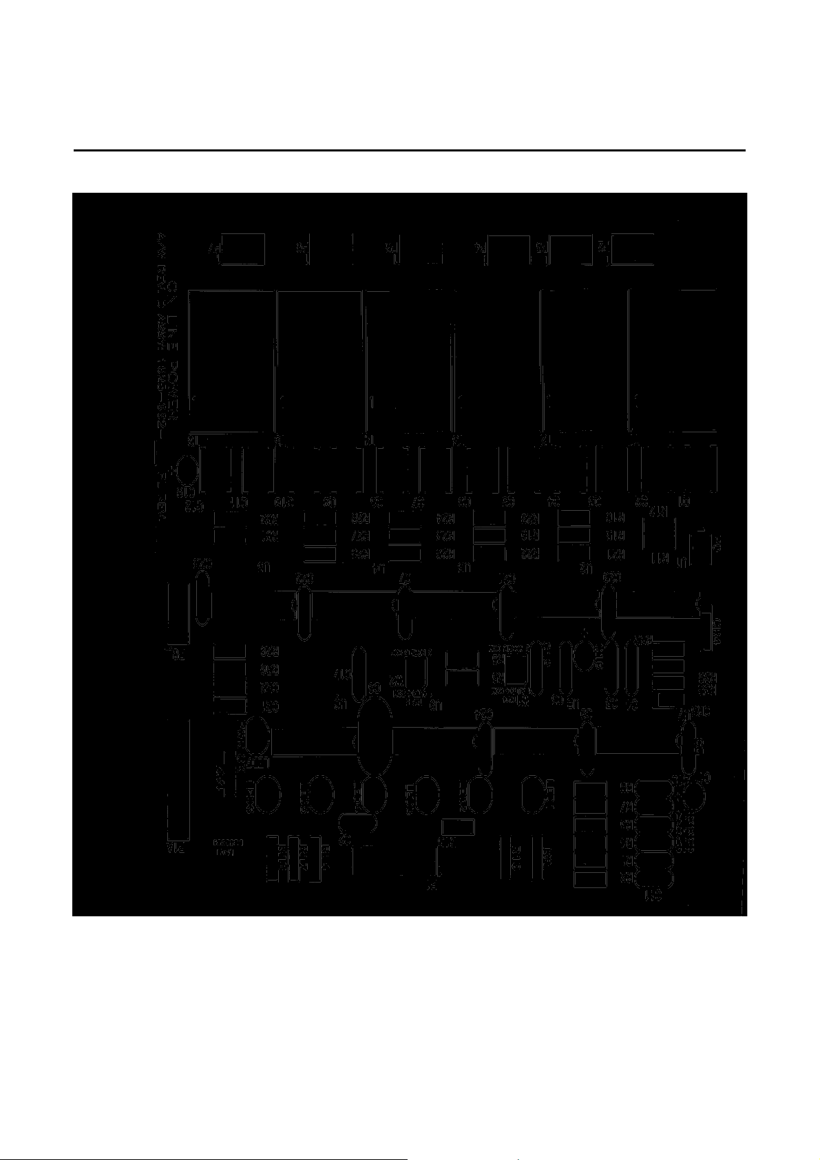
The SCR driver board has seven green LEDs. LED 7 indicates power is applied to the board and is illuminated
any time power to the unit is on. LEDs 1 throug h 6 represent tap settings and only one of these si x LEDs
should be on at any time. See Illustration 3-2. It is no rmal for the LED’s 1 through 6 to delay 6 seco nds after
the power LED has turned on.
If no LED is lit or if two or more LEDs are lit, immediately turn facility circuit breaker OFF or turn IMCB to OFF (if
installed). The regulator can be placed on manual operation for emergency service. See Section 1-7-2.
If only one LED (1 through 6) is lit, perform the following calibration:
PROCEDURE:
1. Turn connected load OFF.
2. Turn facility circuit breaker OFF, lock and tagout in accordance with OSHA Lockout/Tagout requirements.
3. Open Power-Reg, Ultra-Reg, Phase Stabilizer (100 - 400 kVA) as follows:
a. Remove front panel by unbolting six screws at corners and left and right sides of each panel.
4. Open CP 18, Phase Stabilizer (15 - 75 kVA) as follows:
a. Open front door.
b. Set IMCB to OFF (as applicable).
c. Open hinged front panel by unbolting three screws at left side of panel. Swing panel to right.
5. Unlock facility circuit breaker and turn ON.
6. Set IMCB to ON (as applicable).
7. Turn connected load ON.
6002-032 REV H 3-10
Page 50

OnLine Power
3-1-9 Calibrate Control Logic Board (continued)
DANGER!!
FATAL SHOCK HAZARD!! LETHAL VOLTAGES EXIST WITHIN THE UNIT
DURING THE FOLLOWING CHECK. FOLLOW THE STEPS BELOW
EXACTLY. FAILURE TO DO SO COULD RESULT IN SEVERE INJURY OR
DEATH.
8. Make the following adjustments on the Control logic board for phase A: See Illustration 3-1.
a. Measure AC voltage across R1 or R2. Voltage should be between 10 and 100mv.
b. Measure DC voltage across C42.
c. Adjust R62 until voltage reads 8.5 VDC with a load of 1 kw for 50 kVA or less and 2 kw load for 75 kVA or
larger.
Note
Potentiometer R62 is a 30-turn pot. It may require several turns before output level changes.
d. Adjust R39 counter clockwise until LED 6 is lit. See Illustration 3-1 and Illustration 3-2.
e. Measure DC voltage across C42.
f. Adjust R62 until voltage reads 8.5 V.
g. Measure neutral-to-phase A output voltage between transformer terminals X1 and X0.
Refer to Appendix B for transformer terminal configuration.
h. Adjust R39 until output voltage reads 120V or 277V, phase to neutral, depending on rated output voltage.
• Output voltage should be ± 3% of nominal for Power-Reg and Ultra-Reg
Output voltage should be ± 2% of nominal for Phase Stabilizer
Note
Output voltage does not change linearly as potentiometer R39 is rotated. Output voltage does a
step change. Pot R39 is a 30-turn pot. It may require several turns before output level changes.
i. Repeat the procedure on the phase-B and phase-C Control logic boards. Take voltage measurements
between transformer terminals X2 and X0 and between X3 and X0 respectively for phase B and C.
6002-032 REV H 3-11
Page 51

OnLine Power
CR29U9R33
R2
R1
R62
R39 C42
CONTROL LOGIC BOARD
ILLUSTRATION 3-1
6002-032 REV H 3-12
Page 52
OnLine Power
SCR DRIVER BOARD
ILLUSTRATION 3-2
3-2 CONFIGURATION
The unit is shipped factory configured. No configuration is necessary. Do not change tap connections.
6002-032 REV H 3-13
Page 53
OnLine Power
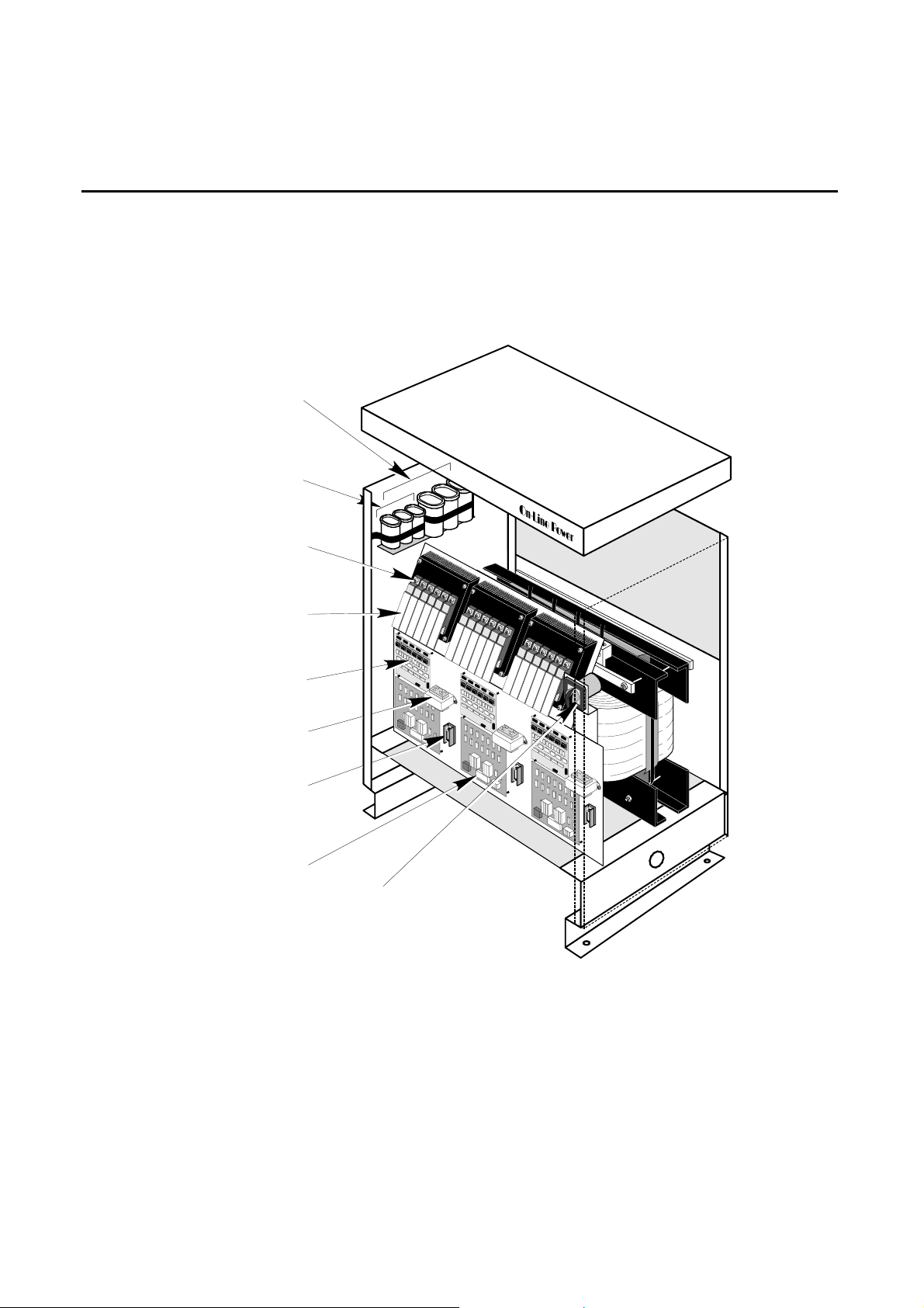
3-3 RENEWAL PARTS, POWER-REG AND ULTRA-REG
INPUT/OUTPUT
FILTER ASSY
9100-001-01
INPUT FILTER ASSY
1690-002
1690-012
SCRs
1625-012-01
1625-004-01
Snubber PCB
1625-002-01
Driver PCB
1400-003
1400-001A
Ref. Transformer
2025-002
Fuse,
Ref. Transformer input
1625-003-01
Control Logic PCB
1680-021
BYPASS SWITCH
6002-032 REV H 3-14
Page 54

OnLine Power
3-3-1 Vendor Parts List, Power-Reg and Ultra-Reg
Vendor No. Vendor Description (Remarks)
1680-021 OnLine Power SWITCH, BYPASS, 1 USED
1680-042 OnLine Power SWITCH, BYPASS, 1 USED
1425-001 OnLine Power TRANSFORMER, CURRENT 50:5, 3 USED (Note 1)
1425-004 OnLine Power TRANSFORMER, CURRENT 1000:1, 3 USED (Note 1)
1425-003 OnLine Power TRANSFORMER, CURRENT 100:5, 3 USED (Note 1)
1425-007 OnLine Power TRANSFORMER, CURRENT 200:5, 3 USED (Note 1)
1425-002 OnLine Power TRANSFORMER, CURRENT 400:5, 3 USED (Note 1)
1690-002 OnLine Power SCR, 15-5 0 KVA MODEL, 18 USED
1690-012 OnLine Power SCR, 75-175 KVA MODEL, 18 USED
1690-011 OnLine Power SCR, 200-400 KVA MODEL, 18 USED
1625-004-01 OnLine Power PCB, SNUBBER, SCR, 15-50 KVA MODEL, 18 USED
1625-012-01 OnLine Power PCB, SNUBBER, SCR, 75-175 KVA MODEL, 18 USED
121543003-02 OnLine Power PCB, SNUBBER, SCR, 200-300 KVA MODEL, 18 USED
1625-002-01 OnLine Power PCB, SCR DRIVER, 3 USED
1400-001A OnLine Power TRANSFORMER, REFERENCE, 208 V PRI, 3 USED
1400-003 OnLine Power TRANSFORMER, REFERENCE, 480 V PRI, 3 USED
9100-001-01 OnLine Power INPUT FILTER ASSY, 1 USED (not shown)
1625-003-01 OnLine Power PCB, CONTROL LOGIC, 3 USED
NOTES:
1. For current transformer part numbers, refer to Tables 3-1.
2. Reference transformer part numbers:
For 208 V input use 1400-001A
For 480 V input use 1400-003
6002-032 REV H 3-15
Page 55
OnLine Power
3-3-1 Vendor Parts List, Power-Reg and Ultra-Reg (continueed)
TABLE 3-1
POWER-REG AND ULTRA-REG CURRENT TRANSFORMERS
SIZE
(KVA)
15 PR015B0500T3
30 PR030B0500T3
50 PR050B0500T3
75 PR075B0500T3
100 PR100H0500T3
125 PR125H0500T3
150 PR150H0500T3
175 PR175H0500T3
200 PR200H0500T3
225 PR225H0500T3
250 PR250H0500T3
300 PR300H0500T3
MODEL
NUMBER
PR015B0900T3
PR015H0500T3
PR015H0900T3
PR030B0900T3
PR030H0500T3
PR030H0900T3
PR050B0900T3
PR050H0500T3
PR050H0900T3
PR075B0900T3
PR075H0500T3
PR075H0900T3
PR100H0900T3
PR125H0900T3
PR150H0900T3
PR175H0900T3
PR200H0900T3
PR225H0900T3
PR250H0900T3
PR300H0900T3
INPUT
VOLTAGE
208 1425-001
480 1425-017
208 1425-007
480 1425-003
208 1425-007
480 1425-003
208 1425-005
480 1425-007
480 1425-007
208 & 480 1425-007
208 & 480 1425-005
208 & 480 1425-005
208 & 480 1425-002
208 & 480 1425-002
208 & 480 1425-004
208 & 480 1425-004
CURRENT
TRANSFORMER
6002-032 REV H 3-16
Page 56
OnLine Power
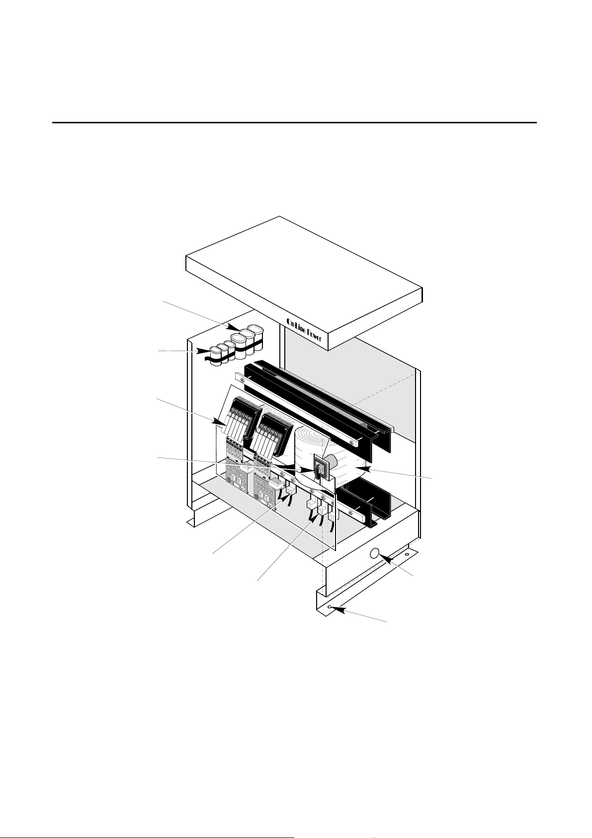
3-4 RENEWAL PARTS, SINGLE PHASE POWER-REG
OUTPUT
FILTER
(OPTIONAL)
INPUT
FILTER
REGULATION
ELECTRONIC
PANEL
BYPASS SWITCH
INPUT POWER
TERMINAL BLOCK
OUTPUT POWER
TERMINAL BLOCKS
MAIN OUTPUT
TRANSFORMER
600V input
120/240V output
INPUT & OUTPUT
CABLE ACCESS
3/8" Dia. Mounting Holes
6002-032 REV H 3-17
Page 57
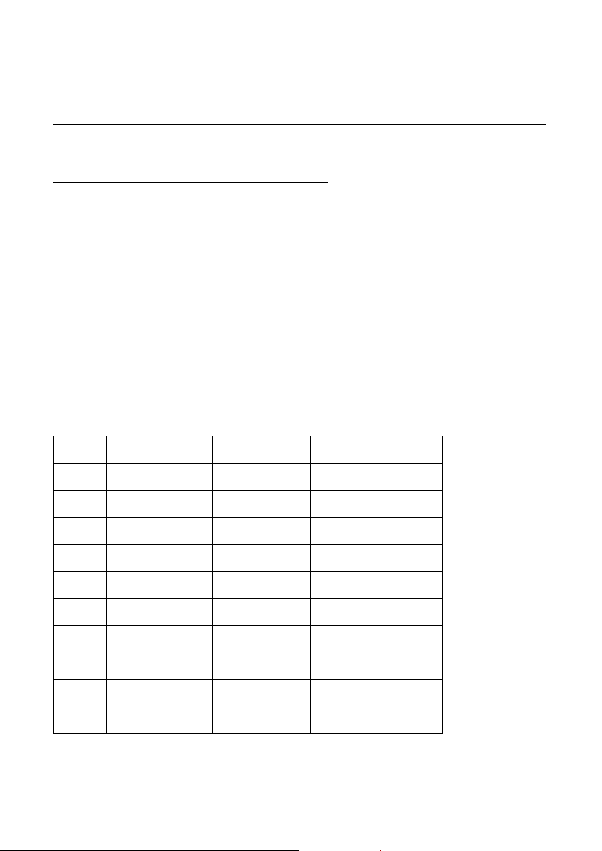
OnLine Power
3-4-1 Vendor Parts List, SINGLE PHASE Power-Reg
Vendor No. Vendor Description (Remarks)
1680-003 OnLine Power SWITCH, BYPASS, 55 AMPS (10-50 KVA), 1 USED
1680-042 OnLine Power SWITCH, BYPASS, 105 AMPS (30-100 KVA), 1 USED
1425-003 OnLine Power TRANSFORMER, CURRENT 100:5, 3 USED (Note 1)
1425-007 OnLine Power TRANSFORMER, CURRENT 200:5, 3 USED (Note 1)
1425-002 OnLine Power TRANSFORMER, CURRENT 400:5, 3 USED (Note 1)
1690-002 OnLine Power SCR, 15-5 0 KVA MODEL, 6 USED
1690-012 OnLine Power SCR, 75-100 KVA MODEL, 6 USED
1625-004-01 OnLine Power PCB, SNUBBER, SCR, 15-50 KVA MODEL, 6 USED
1625-012-01 OnLine Power PCB, SNUBBER, SCR, 75-100 KVA MODEL, 6 USED
1625-002-01 OnLine Power PCB, SCR DRIVER, 3 USED
1400-001A OnLine Power TRANSFORMER, REFERENCE, 208 V PRI, 3 USED
1400-003 OnLine Power TRANSFORMER, REFERENCE, 480 V PRI, 3 USED
9100-001-01 OnLine Power INPUT FILTER ASSY, 1 USED (not shown)
1625-003-01 OnLine Power PCB, CONTROL LOGIC, 3 USED
NOTES:
1. For current transformer part numbers, refer to Tables 3-2.
2. Reference transformer part numbers:
For 208 V input use 1400-001A
For 480 V input use 1400-003
SIZE
(KVA)
POWER-REG AND ULTRA-REG CURRENT TRANSFORMERS
MODEL
NUMBER
10 PR010B0500T1
PR010B0900T1
PR010H0500T1
PR010H0900T1
20 PR020B0500T1
PR020B0900T1
PR020H0500T1
PR020H0900T1
30 PR030B0500T1
PR030B0900T1
PR030H0500T1
PR030H0900T1
50 PR050B0500T1
PR050B0900T1
PR050H0500T1
PR050H0900T1
75 PR075H0500T1
PR075H0900T1
100 PR100H0500T1
PR100H0900T1
TABLE 3-2
VOLTAGE
INPUT
CURRENT
TRANSFORMER
208 1425-001
480 1425-017
208 1425-001
480 1425-017
208 1425-007
480 1425-003
208 1425-007
480 1425-003
480 1425-007
480 1425-007
6002-032 REV H 3-18
Page 58
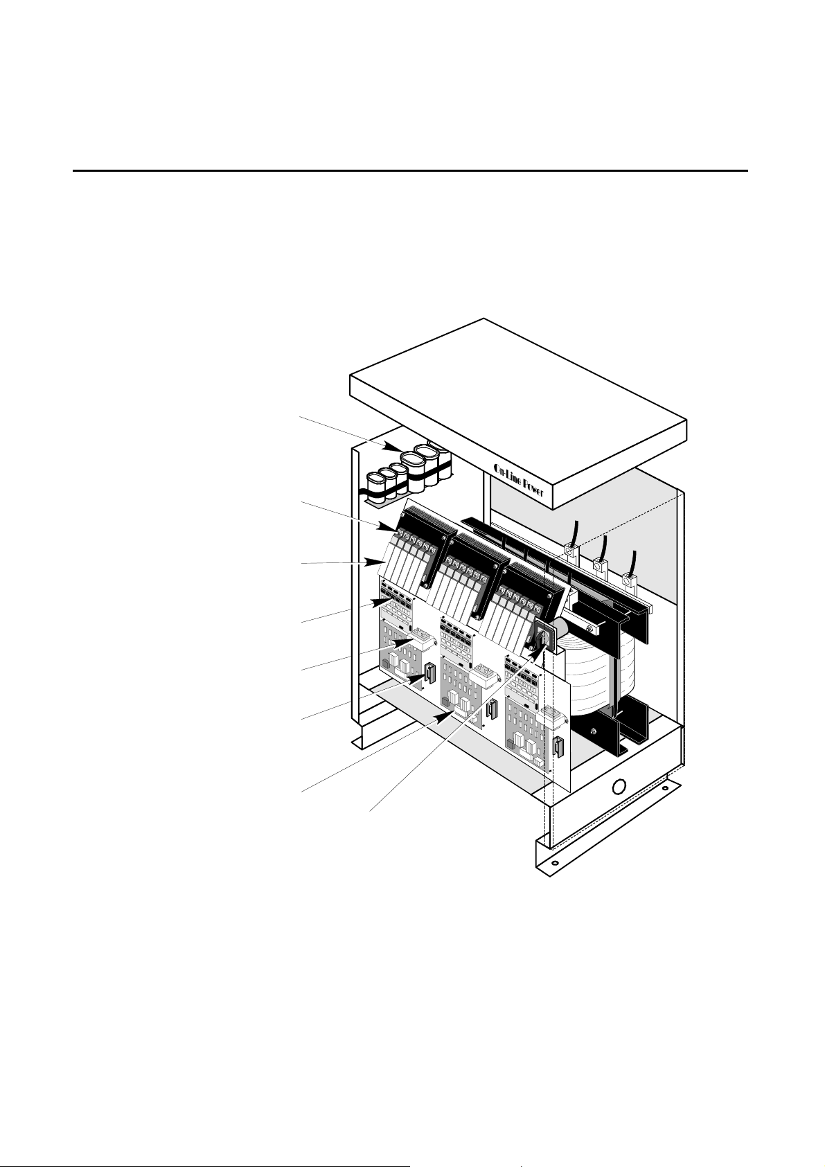
OnLine Power
3-5 RENEWAL PARTS, PHASE STABILIZER (100 - 175 kVA)
9100-006-01
INPUT/OUTPUT
FILTER ASSY
1690-012
SCRs
1625-012-01
Snubber PCB
1625-002-01
Driver PCB
1400-001A
1400-003
Ref. Transformer
2025-002
Fuse,
Ref. Transformer input
1625-003-02
Control Logic PCB
1680-021
Bypass Switch
6002-032 REV H 3-19
Page 59
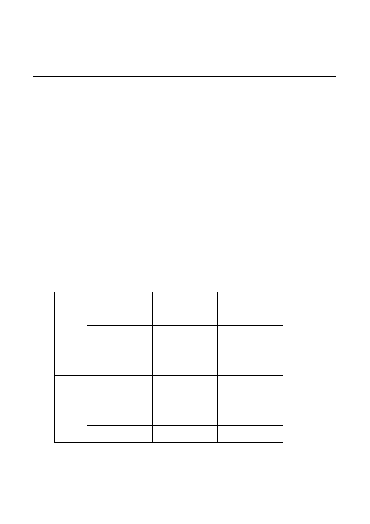
OnLine Power
3-5-1 Vendor Parts List, Phase Stabilizer (15 - 75 kVA)
Vendor No. Vendor Description (Remarks)
1680-021 OnLine Power SWITCH, BYPASS, 1 USED
1425-001 OnLine Power TRANSFORMER, CURRENT 50:5, 3 USED (Note 1)
1425-017 OnLine Power TRANSFORMER, CURRENT 25:5, 3 USED (Note 1)
1425-003 OnLine Power TRANSFORMER, CURRENT 100:5, 3 USED (Note 1)
1425-005 OnLine Power TRANSFORMER, CURRENT 300:5, 3 USED (Note 1)
1425-007 OnLine Power TRANSFORMER, CURRENT 200:5, 3 USED (Note 1)
1690-002 OnLine Power SCR, 15-5 0 KVA MODEL, 18 USED
1690-012 OnLine Power SCR, 75 KVA MODEL, 18 USED
1625-004-01 OnLine Power PCB, SNUBBER, SCR, 15-50 KVA MODEL, 18 USED
1625-012-01 OnLine Power PCB, SNUBBER, SCR, 75 KVA MODEL, 18 USED
1625-002-01 OnLine Power PCB, SCR DRIVER, 3 USED
1400-001A OnLine Power TRANSFORMER, REFERENCE, 208 V PRI, 4 USED (Note 2)
1400-003 OnLine Power TRANSFORMER, REFERENCE, 480 V PRI, 6 USED (Note 2)
9100-001-01 OnLine Power INPUT FILTER ASSY, 1 USED (not shown)
9100-006-01 OnLine Power INPUT/OUTPUT FILTER ASSY, 1 USED (not shown)
NOTES:
1. For current transformer PART numbers, refer to Table 3-3.
2. Reference transformer vendor numbers:
For 208 V input use 1400-001A
For 480 V input use 1400-003
TABLE 3-3
PHASE STABILIZER (15 - 75 kVA) CURRENT TRANSFORMERS
SIZE
(KVA)
15
30
50
75
MODEL
NUMBER
PS015B0500T3
PS015B0900T3
PS015H0500T3
PS015H0900T3
PS030B0500T3
PS030B0900T3
PS030H0500T3
PS030H0900T3
PS050B0500T3
PS050B0900T3
PS050H0500T3
PS050H0900T3
PS075B0500T3
PS075B0900T3
PS075H0500T3
PS075H0900T3
INPUT
VOLTAGE
208 1425-001
480 1425-017
208 1425-007
480 1425-003
208 1425-007
480 1425-003
208 1425-005
480 1425-007
H1, H2, H3
6002-032 REV H 3-20
Page 60
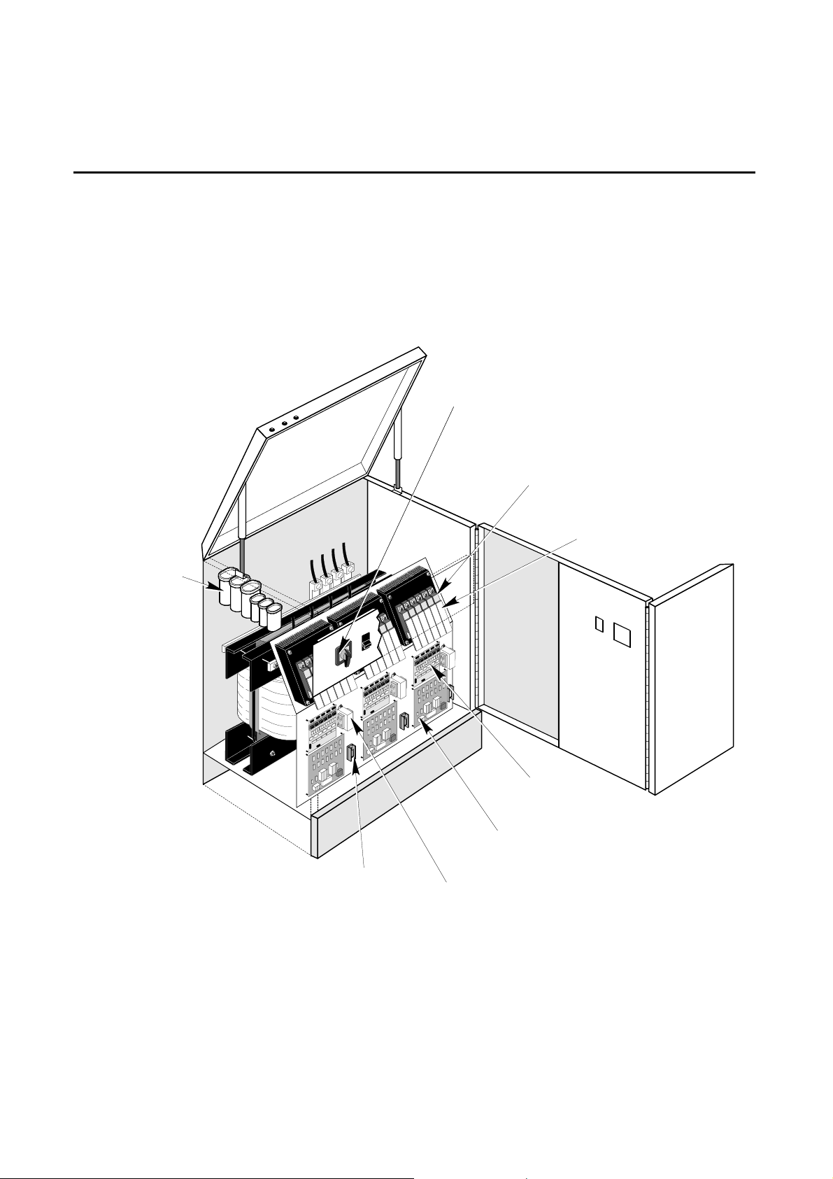
OnLine Power
3-5 RENEWAL PARTS, PHASE STABILIZER (15 - 100 kVA)
1680-021
Bypass Switch
9100-006-01
INPUT/OUTPUT
FILTER ASSY
1690-002
1690-012
SCRs
1625-004-01
1625-012-01
Snubber PCB
2075-002
Fuse,
Ref. Transformer
6002-032 REV H 3-21
1625-002-01
Driver PCB
1625-003-02
Control Logic PCB
SEE NOTE 2
Ref. Transformer
Page 61
OnLine Power
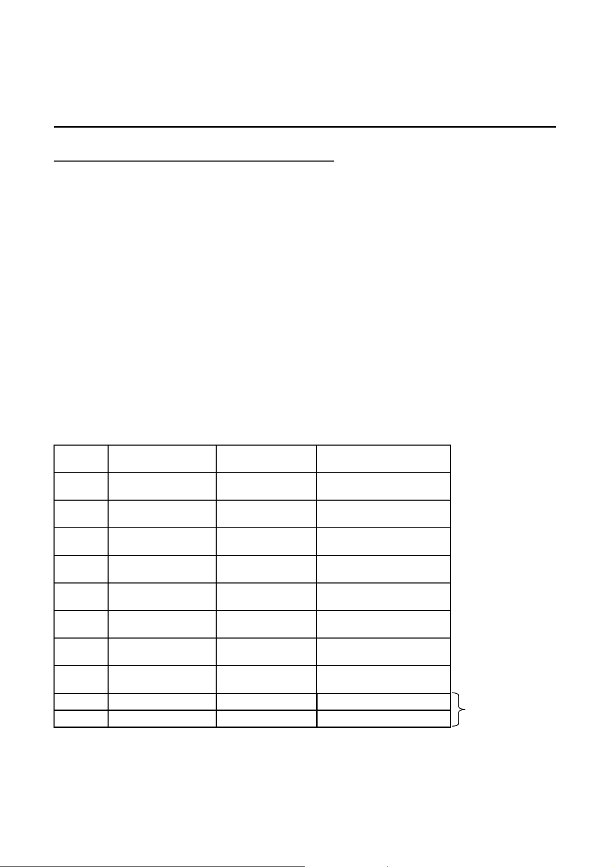
3-5-2 Vendor Parts List, Phase Stabilizer (100 - 400 kVA)
Vendor No. Vendor Description (Remarks)
1680-017 OnLine Power SWITCH, BYPASS, 1 USED
1425-007 OnLine Power TRANSFORMER, CURRENT 200:5, 3 USED (Note 1)
1425-005 OnLine Power TRANSFORMER, CURRENT 300:5, 3 USED (Note 1)
1425-002 OnLine Power TRANSFORMER, CURRENT 400:5, 3 USED (Note 1)
1690-012 OnLine Power SCR, 100-175 KVA MODEL, 18 USED
1690-011 OnLine Power SCR, 200-300 KVA MODEL, 18 USED
1625-012-01 OnLine Power PCB, SNUBBER, SCR, 100-300 KVA MODEL, 18 USED
1625-002-01 OnLine Power PCB, SCR DRIVER, 3 USED
121543003-02 OnLine Power PCB, SNUBBER SCR 200-300 KVA MODEL, 18 USED
1400-001 OnLine Power TRANSFORMER, REFERENCE, 208 V PRI, 4 USED (Note 2)
1400-003 OnLine Power TRANSFORMER, REFERENCE, 480 V PRI, 6 USED (Note 2)
9100-006-01 OnLine Power INPUT/OUTPUT FILTER ASSY, 1 USED (not shown)
1690-234 OnLine Power SCR, AUTO BYPASS MODEL, 200KVA
1690-211 OnLine Power SCR, AUTO BYPASS MODEL, 400KVA
NOTES:
1. For current transformer vendor numbers, refer to Table 3-4.
2. Reference transformer vendor numbers:
For 208 V input use 1400-001A
For 480 V input use 1400-003
SIZE
(KVA)
100
125
150
175
200
225
250
300
200
400
TABLE 3-4
PHASE STABILIZER (100 - 400 KVA) CURRENT TRANSFORMERS
MODEL
NUMBER
PS100H0500T3
INPUT
VOLTAGE
CURRENT
TRANSFORMER
480 1425-007
PS100H0900T3
PS125H0500T3
480 1425-007
PS125H0900T3
PS150H0500T3
480 1425-005
PS150H0900T3
PS175H0500T3
480 1425-005
PS175H0900T3
PS200H0500T3
480 1425-002
PS200H0900T3
PS225H0500T3
480 1425-002
PS225H0900T3
PS250H0500T3
480 1425-004
PS250H0900T3
PS300H0500T3
480 1425-004
PS300H0900T3
PS200H0900T3-00 480 1425-004
PS400H0900T3-00 480 1425-004
With
Auto-by
pass. CKT
New
design)
6002-032 REV H 3-22
Page 62
OnLine Power
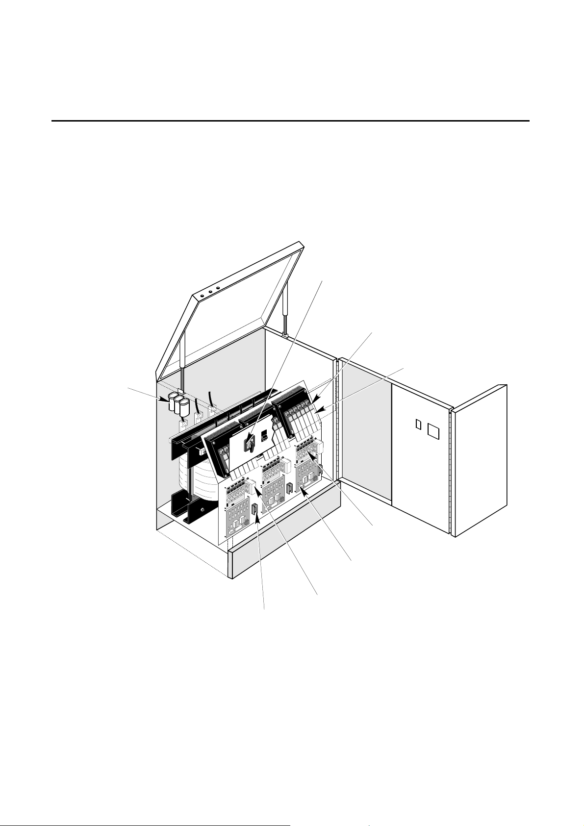
3-6 RENEWAL PARTS, CONSTANT POWER 18
1680-021
Bypass Switch
1690-002
1690-012
SCRs
9100-001-01
INPUT
FILTER ASSY
1625-004-01
1625-012-01
Snubber PCB
1625-002-01
Driver PCB
1625-003-01
Control Logic PCB
SEE NOTE 2
Ref. Transformer
2075-002
Fuse,
Ref. Transformer
6002-032 REV H 3-23
Page 63
OnLine Power
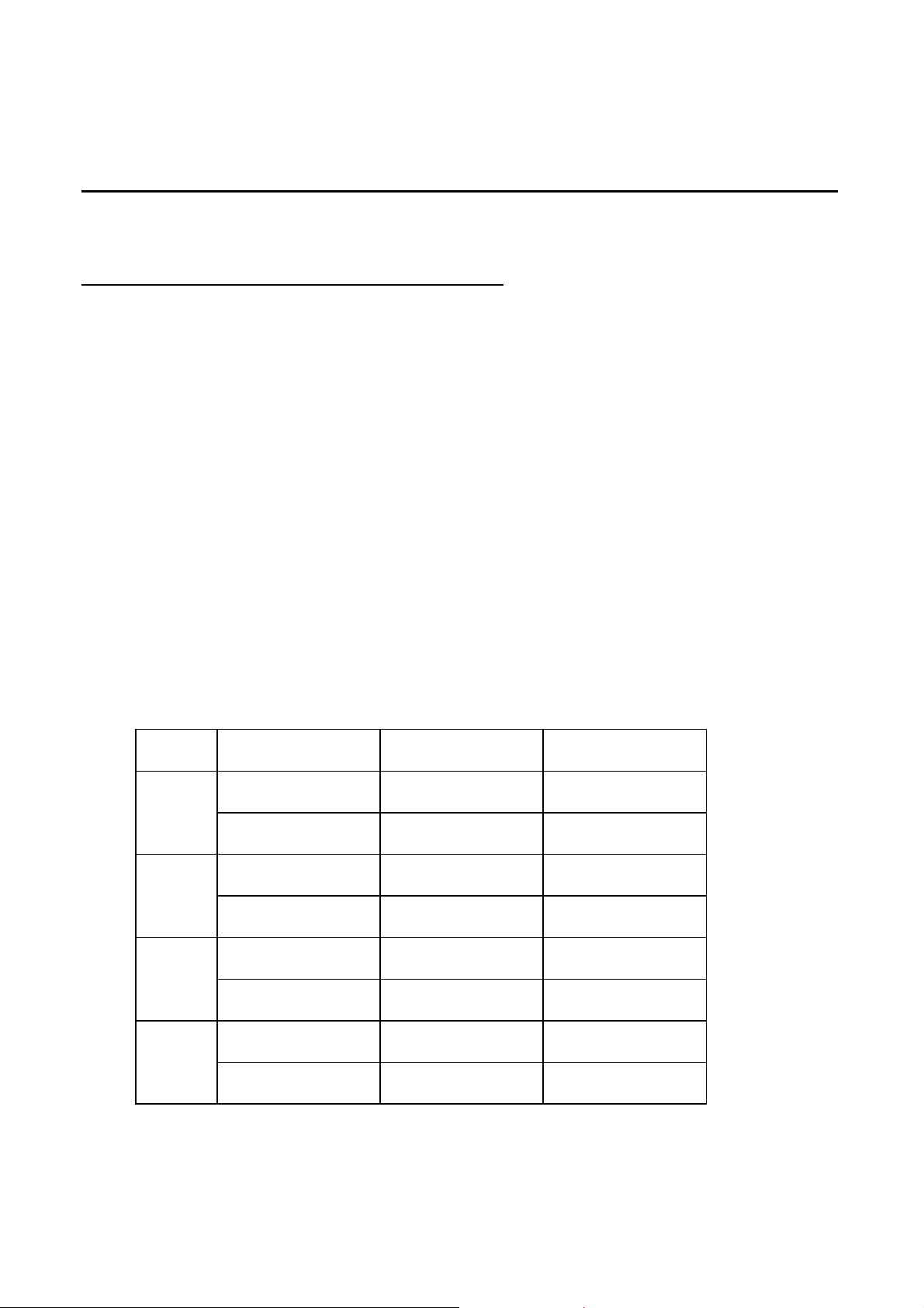
3-6-1 Vendor Parts List, Constant Power 18
Vendor No. Vendor Description (Remarks)
1680-021 OnLine Power SWITCH, BYPASS, 1 USED
1425-001 OnLine Power TRANSFORMER, CURRENT 50:5, 3 USED (Note 1)
1425-017 OnLine Power TRANSFORMER, CURRENT 25:5, 3 USED (Note 1)
1425-003 OnLine Power TRANSFORMER, CURRENT 100:5, 3 USED (Note 1)
1425-005 OnLine Power TRANSFORMER, CURRENT 300:5, 3 USED (Note 1)
1425-007 OnLine Power TRANSFORMER, CURRENT 200:5, 3 USED (Note 1)
1690-002 OnLine Power SCR, 15-5 0 KVA MODEL, 18 USED
1690-012 OnLine Power SCR, 75 KVA MODEL, 18 USED
1625-004-01 OnLine Power PCB, SNUBBER, SCR, 15-50 KVA MODEL, 18 USED
1625-012-01 OnLine Power PCB, SNUBBER, SCR, 75 KVA MODEL, 18 USED
1625-002-01 OnLine Power PCB, SCR DRIVER, 3 USED
1625-003-01 OnLine Power PCB, CONTROL LOGIC BOARD, 3 USED
1400-001A OnLine Power TRANSFORMER, REFERENCE, 208 V PRI, 4 USED (Note 2)
1400-003 OnLine Power TRANSFORMER, REFERENCE, 480 V PRI, 6 USED (Note 2)
9100-001-01 OnLine Power INPUT FILTER ASSY, 1 USED
NOTES:
1. For current transformer vendor numbers, refer to Table 3-5.
2. Reference transformer vendor numbers:
For 208 V input use 1400-001
For 480 V input use 1400-003
TABLE 3-5
CONSTANT POWER 18 CURRENT TRANSFORMERS
SIZE
(KVA)
15
30
50
75
MODEL
NUMBER
AP015B0500T3
AP015B0900T3
AP015H0500T3
AP015H0900T3
AP030B0500T3
AP030B0900T3
AP030H0500T3
AP030H0900T3
AP050B0500T3
AP050B0900T3
AP050H0500T3
AP050H0900T3
AP075B0500T3
AP075B0900T3
AP075H0500T3
AP075H0900T3
INPUT
VOLTAGE
208 1425-001
480 1425-017
208 1425-007
480 1425-003
208 1425-007
480 1425-003
208 1425-005
480 1425-007
H1, H2, H3
6002-032 REV H 3-24
Page 64
OnLine Power
SECTION 4 - OPTIONS
4-1 INTRODUCTION
OnLine Power offers a number of options which can enhance the performance of the Power Conditioner or
Voltage Regulator and expand the units’ power distribution capacity to suit facility requirements.
This section discusses the functions and capabilities of the following options:
• Remote Emergency Power Off (REPO) Station
• Thermal (REPO) Station
• Surge Protection
• Main Input Circuit Breaker
• Output Filtering
Some of the options listed above are provided as standard equipment on some models of OnLine Power
Conditioners and Voltage Regulators while other options are only available on some models. Refer to Table 41 to clarify options availability.
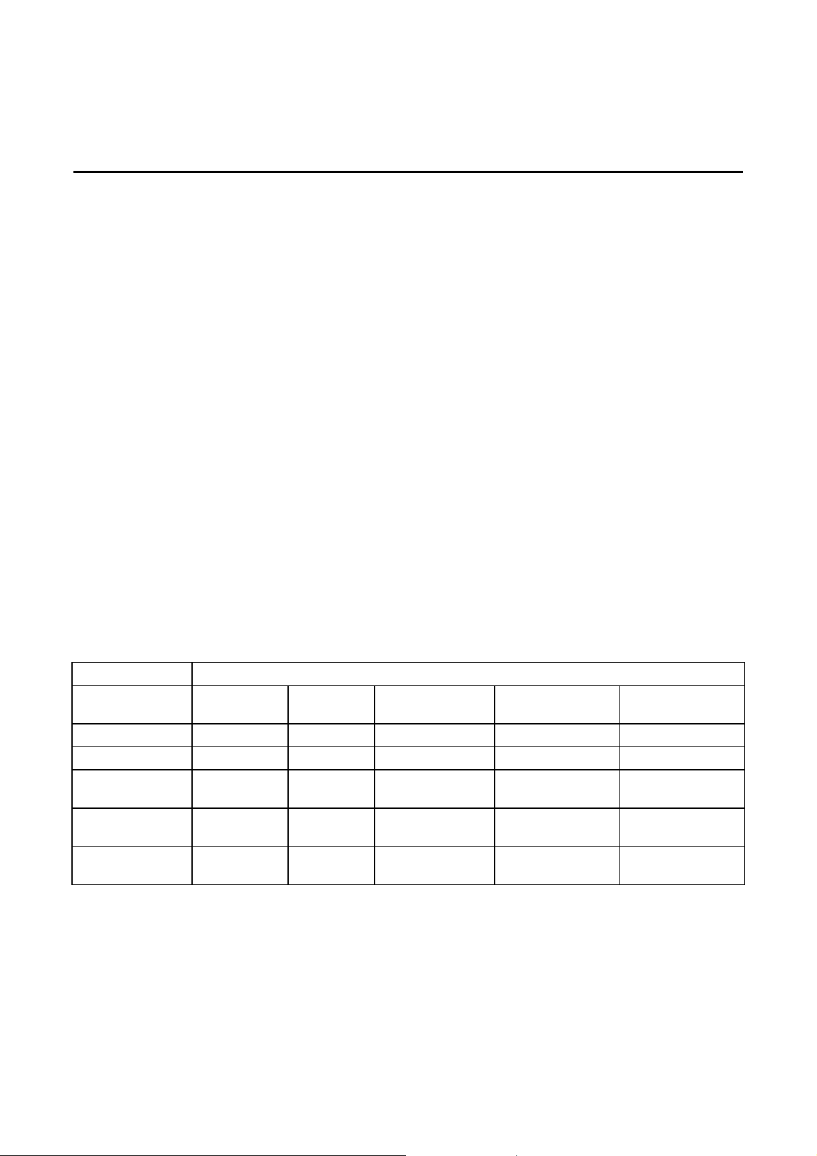
TABLE 4-1
OPTIONS MATRIX
OPTION
REPO
Thermal REPO
Surge
Protection
Main Input
Circuit Breaker
Output
Filtering
Power-Reg Ultra-Reg Constant
N N O N N
N N O N N
O O O S S
N N S O N
O O O S S
MODEL
Power 18
Phase Stabilizer
(15 - 75 kVA)
Phase Stabilizer
(100 - 400 kVA)
TABLE KEY: S = Standard equipment, O = Available as an option, N = Not available for this model.
6002-032 REV H 4-1
Page 65
OnLine Power
4-2 REMOTE EMERGENCY POWER OFF STATION, Constant Power 18
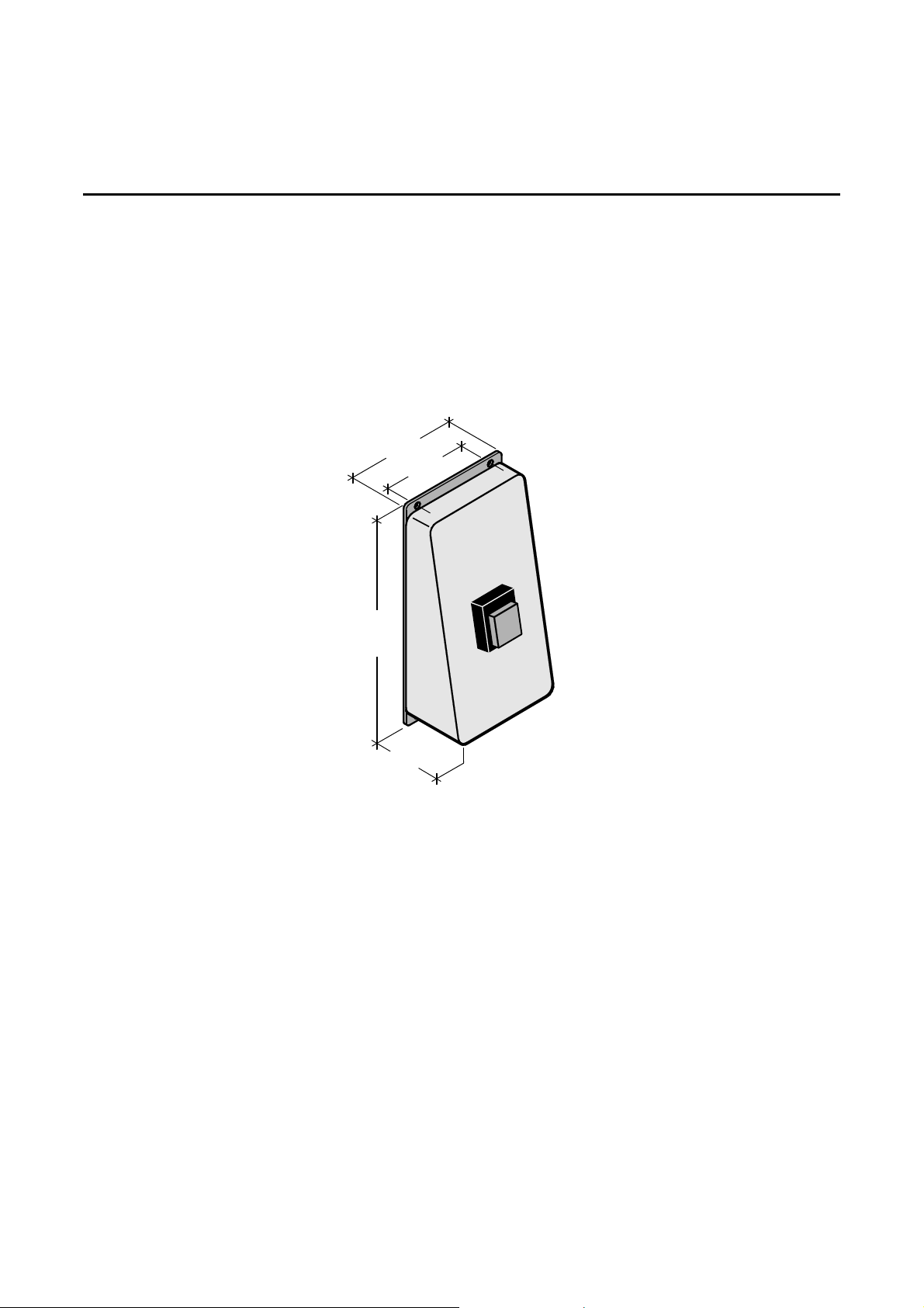
The Remote Emergency Power Off Station (REPO) is a wall-mounted unit that enables operating personnel to
remotely shut down the Power Conditioner or Voltage Regulator in a n emergency. The REPO station consists
of a painted sheet metal enclosure with a guarded, momentary, normally open, red tactile switch. See
Illustration 4-1 for REPO-box size and mounting hole location.
The REPO station is designed to be vertically mounted and can be located anywhere an emergency shut-off is
required. The REPO station is provided with a 5 0-foot, two-conductor cable (15 m). Other length cab les are
available in five-foot increments.
4(10.2)
3(7.6)
)
8
.
7
1
(
7
2(5.1)
REPO BOX
ILLUSTRATION 4-1
4-2-1 Installation for REPO
The REPO cable will be 50 to 100 feet (15 - 30 m) long depending on length ordered. The cable is supplied
with a two-pin connector on one end and bare wires on the other end. The bare wires connect to a terminal
block in the CP 18.
Procedure
1. Select the location for the REPO box.
2. Mount REPO box on wall or other structure using fasteners that are appropriate for the surface on which the
REPO box is to be mounted.
3. Remove REPO box cover.
6002-032 REV H 4-2
Page 66
OnLine Power
4-2-1 Installation for REPO (continued)
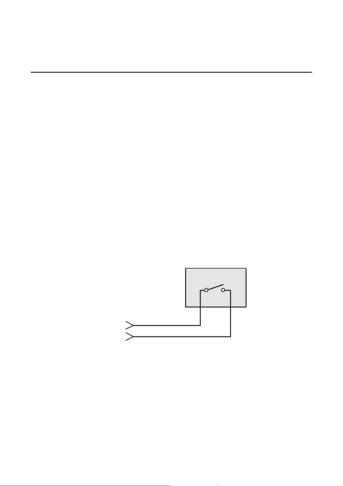
4. Connect 2 wires in REPO cable to terminals on REPO switch as shown in Illustration 4-2.
5. Turn OFF main facility circuit breaker, lock and tagout in accordance with OSHA requirements.
6. Open front door of Power Conditioner.
7. Set IMCB to OFF.
8. Remove floor tiles as required to route REPO cable from REPO box to Power Conditioner.
9. Route REPO cable up through opening in floor (as applicable) and into conduit entry opening.
10. Locate the two-terminal REPO terminal block in the Power Conditioner.
11. Connect the 2 wires in REPO cable to REPO terminal block. See Illustration 4-2.
12. Replace floor tiles as required.
13. Set IMCB to ON.
14. Close front door of Power Conditioner.
15. Set main facility circuit breaker to ON.
TO T.B.
REPO SWITCH
34
N.O.
TB5
+28 VDC
SHUNT TRIP
REPO WIRING
ILLUSTRATION 4-2
6002-032 REV H 4-3
Page 67
OnLine Power
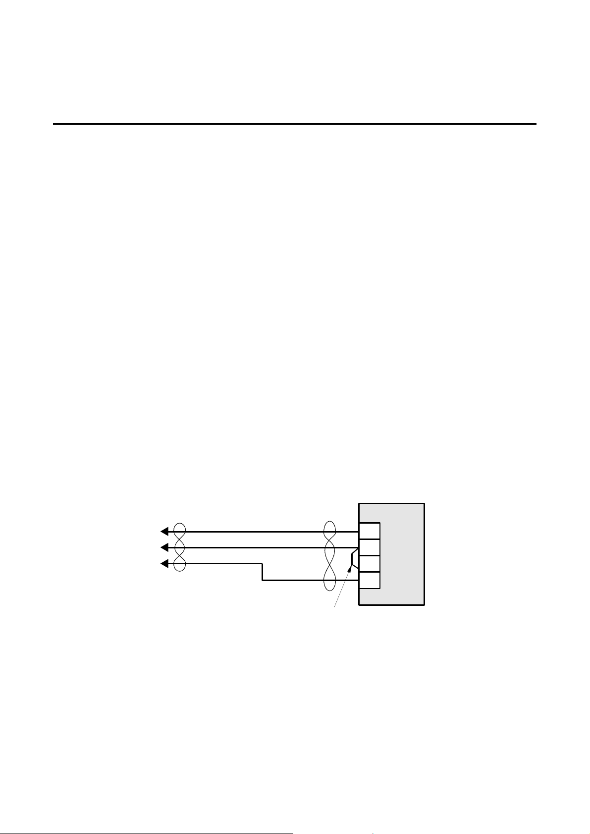
4-3 THERMAL REMOTE EMERGENCY POWER OFF STATION
The Thermal REPO is a wall mounted unit that functions as a dual temperature warning and shutdown monitor.
The first and second stage over temperature settings are field selectable. The Thermal REPO provides a
contact closure for the first stage alarm, and a unit shutdown interface for the second stage over-temperature
response. In addition, the Thermal REPO displays the ambient temperature on a 3-digit display.
The Thermal REPO station is designed to be vertically mounted at eye level or slightly lower. It can be located
anywhere an emergency shut-off is required. The Thermal REPO is provided with a 50-foot (15 m), threeconductor cable. Longer cables are available in five-foot increments up to 100 feet (30 m).
Thermal REPO Specifications:
• Temperature range
• Dimensions
• Weight
4-3-1 Installation for Thermal REPO
The Thermal REPO cable will be 50 to 100 feet (15 - 30 m) long depending on length ordered. The cable is
supplied with bare wires on the both ends. The bar e wire ends connect to the terminals inside the Thermal
REPO enclosure.
WHITE
BLACK
RED
GND
+24VDC
SHUNT TRIP
JUMPER 1 & 12
THERMAL REPO WIRING
ILLUSTRATION 4-3
TWO-STAGE
THERMO
REPO SWITCH
14
12
1
2
6002-032 REV H 4-4
Page 68

OnLine Power
4-3-1 Installation for Thermal REPO (continued)
Note
The Thermal REPO is shipped with separate operating instructions.
Procedure
1. Select the location for the Thermal REPO box.
2. Remove Thermal REPO box cover.
3. Mount Thermal REPO box on wall or other structure using mounting holes located in the back of Thermal
REPO enclosure. Use fasteners that are appropriate for the surface on which the Thermal REPO box is to
be mounted.
4. Connect three wires in Thermal REPO cable to terminals on Thermal REPO switch as shown in Illustration 4-
3.
5. Turn OFF main facility circuit breaker, lock and tagout in accordance with OSHA requirements.
6. Open front door of Power Conditioner.
7. Set IMCB to OFF.
8. Route Thermal REPO cable from Thermal REPO box to Pow er Conditioner. Remove floor tiles as required.
9. Open front panel of Power Conditioner.
10. Route Thermal REPO cable up through opening in floor (as applicable) and into conduit entry opening.
11. Locate terminal block on the Power Conditioner.
12. Connect the three wires to the terminal block.
13. Replace floor tiles as required.
14. Close front panel of Power Conditioner.
15. Set IMCB to ON.
16. Close front door of Power Conditioner.
17. Set main facility circuit breaker to ON.
6002-032 REV H 4-5
Page 69

OnLine Power
4-4 SURGE PROTECTION
The Secondary Surge Suppression circuit consists of a special output filter comprising fuse-protected metal
oxide varistors and indicator lights. This option is designed to reduce the effect of load induced ele ctrical noise
on other electronics such as connected load s. In addition, the secondary surge suppression circuit prevents
electronic and electromechanical devices from interfering with each other.
The characteristics of the filter assembly are as follows:
• Parallel (shunt) operation
• R esponse time of less than five nanoseconds
• Repetitive transient to 5,000 volts per second
• Clamping voltage (208Y/120):
Ratio 1.2, 144 Va c line to neutral, 364 Vac line to line
Ratio 1.75, 210 Vac line to neutral, 364 Vac line to line
• Peak pulse power rating:
27 kW line to neutral
13.4 kW line to line
• Fuse d for c ircuit protection with visu al blown fuse indicators (one per phase)
The secondary surge suppression circuit is factory installed at the time of production. No assembly or
adjustments are required.
4-5 MAIN INPUT CIRCUIT BREAKER, Phase Stabilizer (15 - 75 kVA)
The optional MAIN INPUT CIRCUIT BREAKER (IMCB) is used to switch power to the Phase Stabilizer unit ON
and OFF. The IMCB is located on the front panel of the unit, behind the hinged front door.
Be sure to observe ALL warnings and cautions when setting the IMCB to ON or OFF.
This option is factory installed at the time of production. No assembly or adjustments are required.
4-5-1 Main Input Circuit Breaker with Manual Reset Option.
This option prevents the circuit breaker from turning on o nce it trips due to over temperature or other critical
emergency turn off commands. The input circuit breaker will stay in the off position until the operator resets it
manually by pushing the reset switch and closing the input circuit breaker. The input circuit breaker can be
closed only after pushing the reset switch.
6002-032 REV H 4-6
Page 70
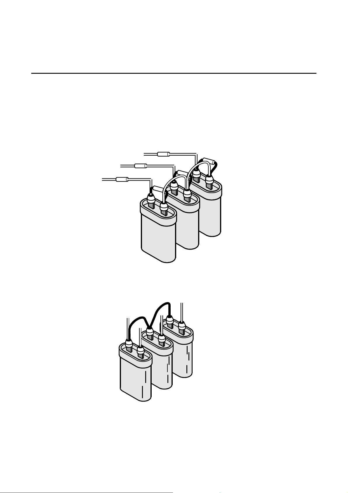
OnLine Power
4-6 INPUT/OUTPUT FILTERING
The Input/Output filter comprises an input filter installed on the primary and an output filter installed on the
secondary of the transformer. The input filter consists of a resistor/capacitor network which a cts as a large
snubber circuit to eliminate high frequency impulses from enter ing the power system. The o utput filter consists
of a capacitor network which, when coupled with the primary filter, virtually eliminates most electronic noise
from reaching the applied load or be ing fed back to the unit from noise generating loads. See Illustr ation 4-4
and 4-5.
R3
R6
R5
R4
(L1)
H1
(L2)
H2
R1
(L3)
H3
R2
X0
C1
INPUT FILTER WIRING
ILLUSTRATION 4-4
X2
X1
C5
C4
C3
C2
X3
C6
OUTPUT FILTER WIRING
ILLUSTRATION 4-5
6002-032 REV H 4-7
Page 71
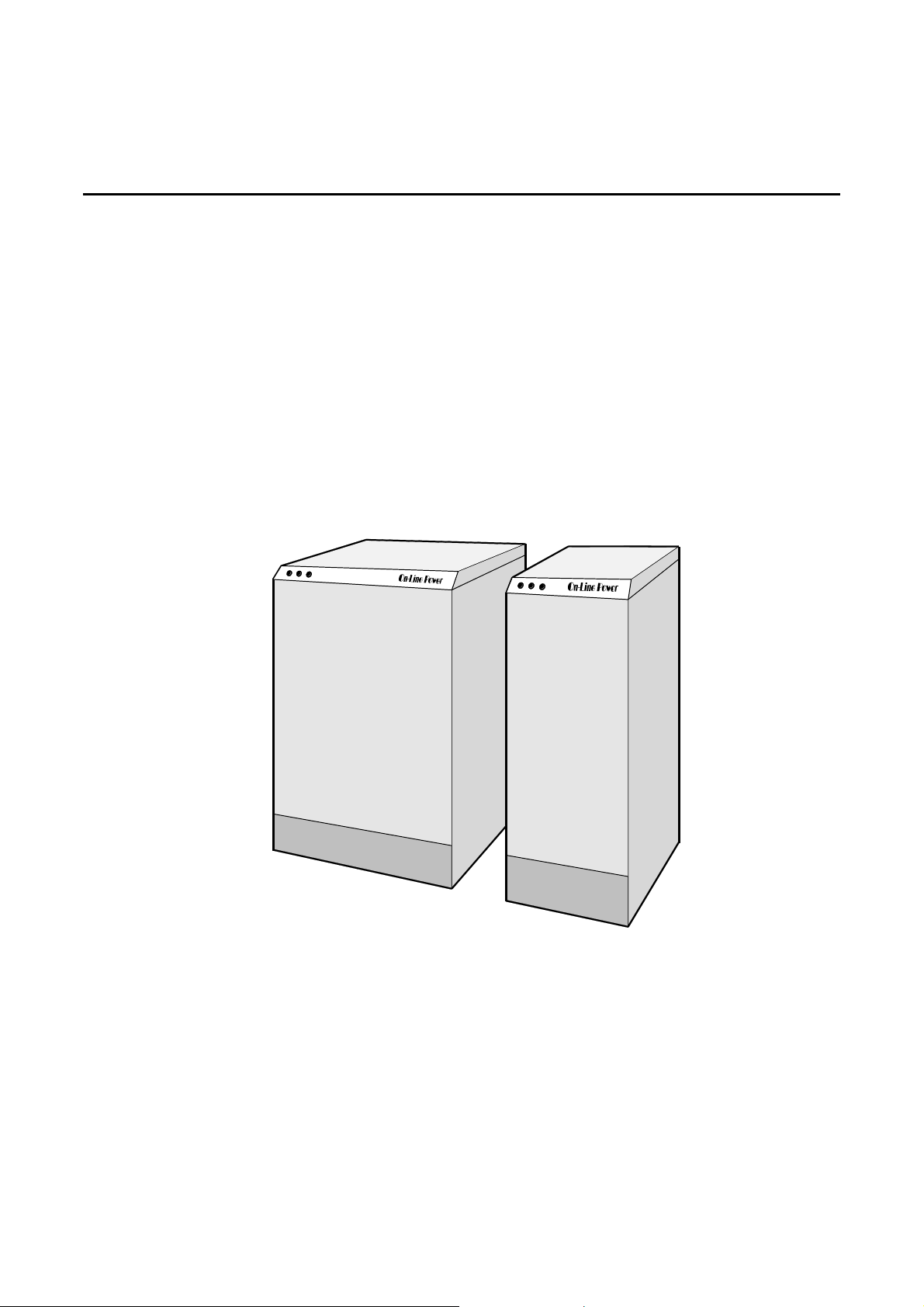
OnLine Power
4-7 POWER ISLAND
4-7-1 Features
The Power Island is a modular power distribution center which can be used with either the Power Conditioner or
Voltage Regulator. The Power Island can extend the distribution capability of the Po wer Conditioner or Voltage
Regulator by up to 42 and 84 pole positions.
The 225-amp or 450-amp Power Island is available in two models. The Power Island-42 can accommodate
one 42-pole panelboard and the Power Island 84 ca n accommodate two 42-pole panelboards. The standard
panelboard is a 225-amp Square-D Snap-On. For other panelboard configuration s, refer to your OnLine Power
Sales Representative. The style and function of both Power Island models coordina tes with and complements
the design of the Constant Power 18 and the Phase Stabilizer in the 15 to 75 kVA sizes. See Illustration 4-6.
The Power Island provides three neon phase indicators, located on the front of the unit. Each phase is
independently monitored. If a phase is lost the corresponding indicator will extinguish, showing which phase is
having the problem.
Power-Island 84
POWER ISLAND
ILLUSTRATION 4-6
6002-032 REV H 4-8
Power-Island 42
Page 72
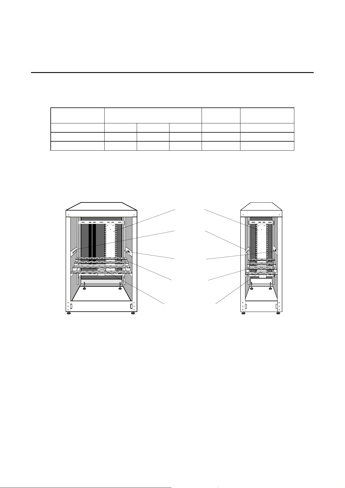
OnLine Power
4-7-2 Power Island Specifications
MODEL DIMENSIONS in. (cm)
Power Island/42 14 (36) 42 (107) 24 (61) 175 (74) 75 (360)
Power Island/84 28 (71) 42 (107) 24 (61) 225 (102) 48 (236)
WEIGHT
lbs. (kg)
FLOOR LOADING
lbs/ft (kg/m )
W H D
Panelboards
Full Capacity
Ground Bus
Power-Island 84
REAR VIEW
Isolated
Full Capacity
Neutral Bus
Tiered & Slotted
Output Conduit
Landing Brackets
Main Input
Conduit Landing Bracket
Power-Island 42
REAR VIEW
POWER ISLAND FEATURES
ILLUSTRATION 4-7
6002-032 REV H 4-9
Page 73
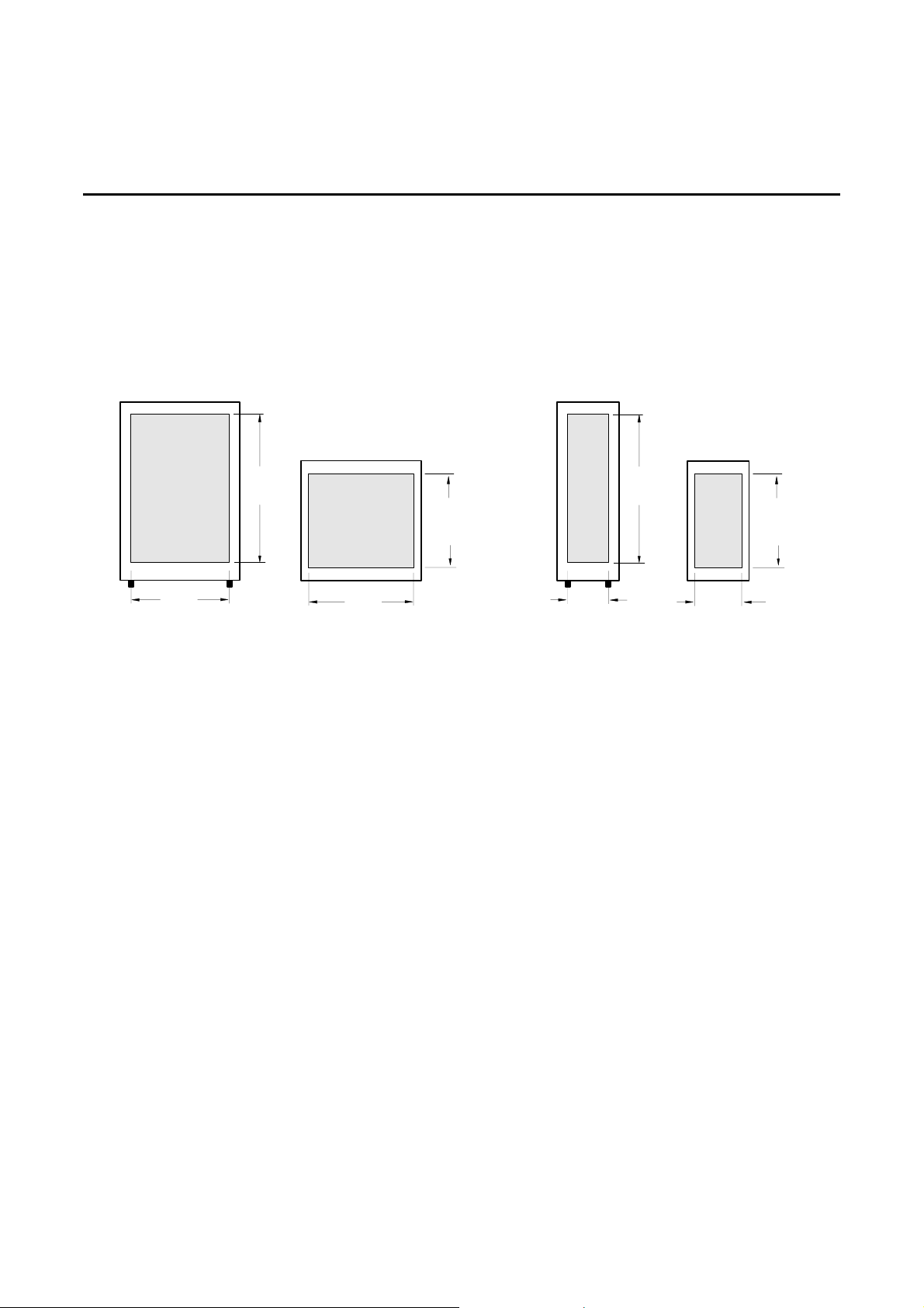
OnLine Power
4-7-3 Preinstallation
Determine the location of the Power Island and routing of input and output cables prior to installation. Because
the Power Island is a stand-alone unit it can be placed as close to the load as possible. The following
Illustrations are provided to aid in determining cable access, floor layout and service clearances.
See Illustrations 4-8, 4-9 and 4-10.
24"
(61cm)
REAR VIEW
Power-Island 84
34"
(86cm)
26"
(66cm)
BOTTOM VIEW
POWER ISLAND CABLE ACCESS
16"
(41cm)
ILLUSTRATION 4-8
10"
(25cm)
REAR VIEW
Power-Island 42
34"
(86cm)
16"
(41cm)
12"
(30cm)
BOTTOM VIEW
6002-032 REV H 4-10
Page 74
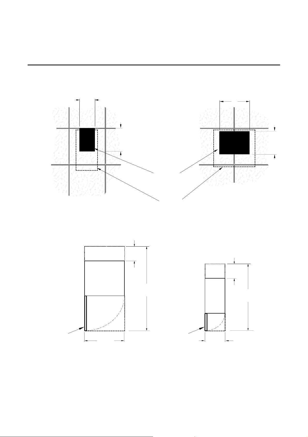
OnLine Power
4-7-3 Preinstallation (continued)
10
(25)
FRONT
14"
(36cm)
FLOOR TILE
CUTOUT
UNIT
FOOTPRINT
POWER ISLAND FLOOR TILE CUTOUT
ILLUSTRATION 4-9
18
(46)
14"
(36cm)
FRONT
18"
(46cm)
70"
(178cm)
FRONT DOOR
FULLY OPEN
29.5"
(75cm)
Power-Island 84
POWER ISLAND DIMENSIONS AND CLEARANCES
ILLUSTRATION 4-10
6002-032 REV H 4-11
FRONT DOOR
FULLY OPEN
15.5"
(39cm)
Power-Island 42
18"
(46)
56"
(142cm)
Page 75
OnLine Power
4-7-4 Input Interconnect Cable Instal latio n
An optional 225-amp or 450-amp Output Interconnect Cable is available to connect the Power Island to the
Power Conditioner or Voltage Regulator. This cable is specified in 5 -foot increments to a maximum of 50 feet
(15 m).
The following instructions cover installation of the Input Interconnect Cable to the Power Conditioner or Voltage
Regulator. If a Power Island 84 is being installed, two input interconnect cables are required.
Procedure
1. Turn OFF main facility circuit breaker to power conditioner or voltage regulators lock and tagout in
accordance with OSHA requirements.
2. Open front door of Power Island.
DANGER!!
POTENTIAL ELECTRICAL HAZARDS TO HUMAN LIFE EXIST WITHIN THIS
EQUIPMENT WHEN ENERGIZED. DISCONNECT INPUT POWER TO UNIT
BEFORE OPENING ENCLOSURE OR TOUCHING INTE RN AL PA RT S.
3. Verify that IMCB is set to OFF.
4. Verify that all output circuit breakers are set to OFF.
5. Remove front panel of Power Island.
6. Remove floor tiles as required and route Input Interconnect Cable between Power Island and Power
Conditioner or Voltage Regulator.
7. Route Input Interconnect Cable up through floor opening (as applicable) and into Main Input Conduit Landing
Bracket.
8. Connect the grounding conductor to the ground bus in the Power Island.
9. Connect the power conductors to the Input Main Circuit Breaker located at the top of the panelboard in the
Power Island.
6002-032 REV H 4-12
Page 76

OnLine Power
4-7-4 Output Interconnect Cable Installation (continued)
10. Access the interior of Power Conditioner or Voltage Regulator as follows:
• Constant Power 18 and Phase Stabilizer (15 - 75 kVA)
a. Raise hinged lid.
b. The Power Island Interconnect cable can be routed through the bottom or through the right side of the CP
18 or Phase Stabilizer.
• Power-Reg, Ultra-Reg, Phase Stabilizer (100 - 400 kVA)
a. Remove top cover by unbolting two bolts on each side of cover.
b. Remove front panel by unbolting six bolts.
11. Route Output Interconnect Cable up through floor opening (as applicable) and into conduit entry opening.
12. Connect the grounding conductor to the ground bus in the Power Conditioner or Voltage Regulator.
13. Connect the power conductors to the Output Power Terminal Block in the Power Conditioner or Voltage
Regulator.
4-7-5 Output Cable Installation
The following instructions cover installation of the Output Cable s between the connected loads and the Power
Island:
Note
The equipment to be connected to the Power Island may requ ire special grounding procedures.
Refer to technical documentation which accompanies that equipment.
Procedure
1. Turn OFF facility circuit breaker to power conditioner or voltage regulator, lock and tagout according to
OSHA requirements.
2. Open front door of Power Island.
3. Verify that IMCB is set to OFF.
4. Verify that all output circuit breakers are set to OFF.
6002-032 REV H 4-13
Page 77

OnLine Power
4-7-5 Output Cable Installation (continued)
DANGER!!
POTENTIAL ELECTRICAL HAZARDS TO HUMAN LIFE EXIST WITHIN THIS
EQUIPMENT WHEN ENERGIZED. DISCONNECT INPUT POWER TO UNIT
BEFORE OPENING ENCLOSURE OR TOUCHING INTE RN AL PA RT S.
5. Open front door of Power Island.
6. Open hinged front panel by unbolting the three screws on the left side of panel and swinging panel to the
right.
7. Remove rear panel by unbolting 6 screws located on the corners and right and left sides of the panel.
8. Remove floor tiles as required.
9. Route output cable between equipment to be powered and Power Island.
10. Pass output cable through floor opening and up into cable landing bracket.
11. Secure conduit fitting to landing bracket. Install noninsulated bushings on all conduits and flexes.
12. Route and connect the 1 to 3 power wires to output circuit breaker.
13. Route and connect the ground wire to the ground bus. See Illustration 4-7 for location of ground bus.
14. Route and connect the neutral wire to the neutral bus. See Illustration 4-7 for location of neutral bus.
15. Replace rear panel.
16. Replace hinged front panel.
6002-032 REV H 4-14
Page 78
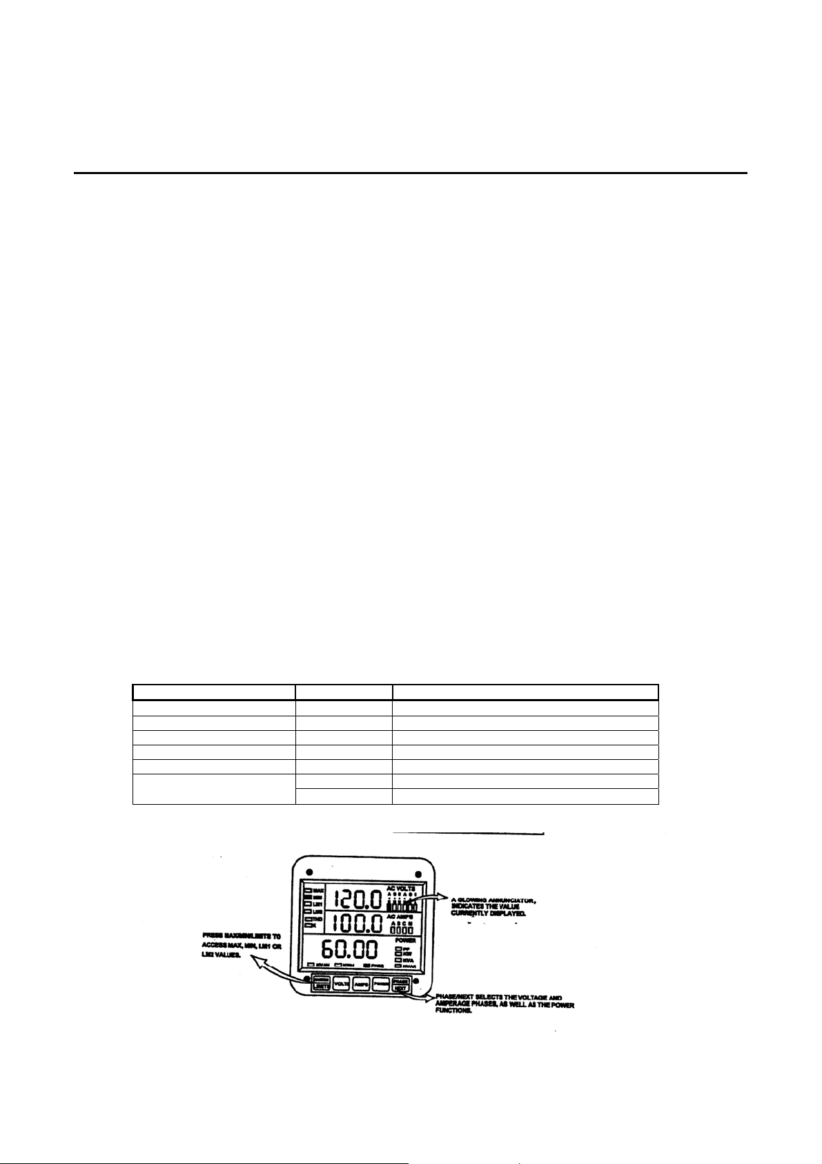
OnLine Power
V
4.8 OUTPUT METER
This meter display the following
LOCAL METERING – STANDARD EXISTING
DMMS 300+ (using 4 ½ “ square meter)
*DISPLAY 3-PHASE
VOLT A-N
VOLT B-N
VOLT C-N
VOLT A-B
VOLT B-C
VOLT C-A
AMP A
AMP B
AMP C
POWER
± KW
± KVAR
KVA
± PF
FREQ.
± TOTAL KWH
TOTAL KVAH
The DMMS 300+ and DMMS 350 display 17 instantaneous electrical parameters. Values for
each parameter are accessed through the keypad on the meter’s front panel (see Figure 5.1).
The DMMS 425 accesses information in the same manner as the DMMS 300+ and DMMS
350. The key strokes for each model are identical.
OLTS AMPS POWER A, B, C
A – N A ± KW
B – N B ± KVAR
C – N C KVA
A – B N ± PF
B – C FREQ
C – A
± TOTAL KWH
TOTAL KVAH (N/A on DMMS 425)
6002-032 REV H 4-15
Page 79
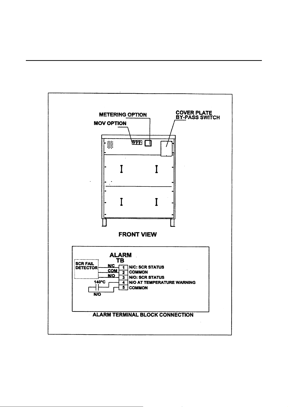
OnLine Power
4.9 ALARM, MOV STATUS
6002-032 REV H 4-16
Page 80
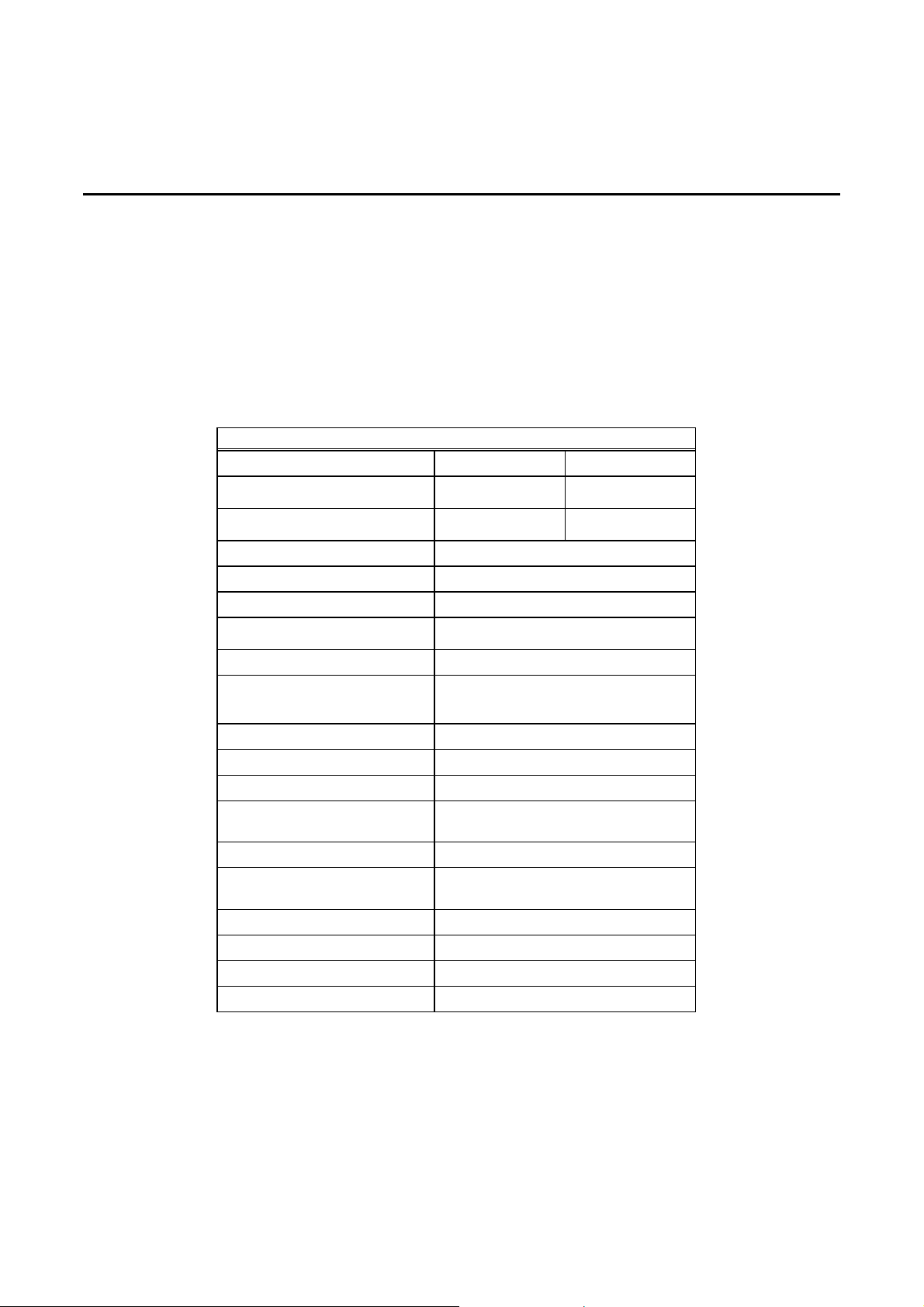
OnLine Power
NOMINAL INPUT VOLTAGE
INPUT VOLTAGE RANGE
APPENDIX A - SPECIFICATIONS
TABLE A-1
SPECIFICATIONS
POWER-REG AND ULTRA-REG
208 VAC 480 VAC
154 - 229 355 - 528
MAXIMUM INPUT VOLTAGE
NOMINAL RATED CURRENT (A)
FREQUENC Y (Hz)
OUTPUT VOLTAGE REGULATION ± 3% Typical, ± 4% Maximum
LINE-TO-LINE VARIATION
RESPONSE TIME 1 Cycle Typical
FILTERS:
INPUT
OUTPUT
COOLING REQUIREMENT (BTU/hr)
WEIGHT lbs (kg) (estimated)
OUTPUT VOLTAGE
CAPACITY (KVA)
NUMBER OF PHASES
SURGE RATING
HARMONICS ADDED
POWER FACTOR
AMBIENT TEMPERATURE °F (°C)
SIZE H X W X D in. (cm)
229 528
See Table 2-1
60
LESS THAN 2%
YES
Optional
See Table 2-1
See Table 2-1
208Y120 VAC or 480Y277 VAC
15, 30, 50, 75, 100, 125, 150,
175, 200, 225, 250, 300, 400 kVA
3
200% of Full Load for 10 Seconds
1000% of Full Load for 1 Cycle
1% Maximum
Greater Than 96%
80 (26.7)
See Table 2-1
6002-032 REV H A-1
Page 81
OnLine Power
NOMINAL INPUT VOLTAGE
INPUT VOLTAGE RANGE
MAXIMUM INPUT VOLTAGE
NOMINAL RATED CURRENT (A)
FREQUENCY (Hz)
OUTPUT VOLTAGE REGULATION ± 1.5%Typical, ± 2% Maximum
LINE-TO-LINE VARIATION
RESPONSE TIME 1 Cycle Typical
FILTERS:
INPUT
OUTPUT
SECONDARY SURGE SUPPRESSION
COOLING REQUIREMENT (BTU/hr)
WEIGHT lbs (kg) (estimated)
OUTPUT VOLTAGE
CAPACITY (KVA)
NUMBER OF PHASES
SURGE RATING
HARMONICS ADDED
POWER EFFICIENCY
AMBIENT TEMPERATURE °F (°C)
SIZE H X W X D in. (cm)
TABLE A-2
SPECIFICATIONS
PHASE STABILIZER
208 VAC 480 VAC
187 - 225 432-518
225 518
See Table 2-4
60
LESS THAN 2%
YES
YES
YES
See Table 2-4
See Table 2-4
208Y120 VAC or 480Y277 VAC
15, 30, 50, 75, 100, 125, 150, 175, 200, 225, 250, 300,400 kVA
3
200% For 10 Seconds
1% Maximum
Greater Than 96%
80 (26.7)
See Table 2-4
6002-032 REV H A-2
Page 82
OnLine Power
NOMINAL INPUT VOLTAGE
INPUT VOLTAGE RANGE
MAXIMUM INPUT VOLTAGE
NOMINAL RATED CURRENT (A)
FREQUENCY (Hz)
OUTPUT VOLTAGE REGULATION ± 3% Typical, ± 4% Maximum
LINE-TO-LINE VARIATION
RESPONSE TIME 1 Cycle Typical
FILTERS:
INPUT
OUTPUT
COOLING REQUIREMENT (BTU/hr)
WEIGHT lbs (kg) (estimated)
OUTPUT VOLTAGE
CAPACITY (KVA)
NUMBER OF PHASES
SURGE RATING
HARMONICS ADDED
POWER EFFICIENCY
AMBIENT TEMPERATURE °F (°C)
SIZE H X W X D in. (cm)
TABLE A-3
SPECIFICATIONS
CONSTANT POWER 18
208 VAC 480 VAC
154 - 229 355-528
229 528
See Table 2-3
60
LESS THAN 2%
YES
Optional
See Table 2-3
See Table 2-3
208Y120 VAC or 480Y277 VAC
15, 30, 50, 75 kVA
3
200% of Full Load for 10 Seconds
1000% of Full Load for 1 Cycle
1% Maximum
Greater Than 96%
80 (26.7)
42 X 32 X 22 (107 X 81 X 56)
6002-032 REV H A-3
Page 83
OnLine Power
APPENDIX B
SPECIAL OPTIONS/PROJECT
B.1
POWER REGULATOR ELECTRICAL RATING:
KVA INPUT
VOLTAGE
3PHASE, DELTA
300 460V 395 AMP 460Y/266V 396.5 AMP 42650
INPUT
RATED
CURRENT
OUTPUT
VOLTAGE
3 PHASE
OUTPUT
RATED
CURRENT
BTU/HR CABINET SIZE
H X W X , IN (MM)
70 (1778) X 58.5 (1486) X 42 (1067)
6002-032 REV H B-
1
Page 84

OnLine Power
1. SUMMERY OF COMPONENTS: (refer to block diagram B-1 for detail):
A/B INPUT/OUTPUT TERMINALS:
Input and Output power connections are made at the terminals located beneath the
Transformer.
C TVSS:
Meets UL 1449 Third Edition, 50kA surge capacity.
D MANUAL BYPASS SWITCH (Regulation only):
The bypass switch is located behind the front panel. This switch bypasses voltage
regulation but maintains the functioning of the voltage change/isolation
between input and output.
The bypass switch is a “break-before make” switch. (Note: Unit must be powered off before
operating this switch).
E AUTO BYPASS SWITCH:
Will provide output power to critical load in case of malfunction, one contactor will be DeEnergized and the other will close to bypass the electronics upon conditions such as over
temperature, SCR fail, Input over load/under voltage, None latching.
F INPUT/OUTPUT FILTER:
The Input filter is installed on the primary side of the transformer. The input filter consists of a
resistor/capacitor netw ork whic h acts as a large snub ber c ircuit to eliminate high frequency
impulses from entering the power system.
The Output filter is installed on the transformer secondary. It consists of a capacitor network
which prevents noise from being fed back to the unit from noise generating loads.
G REGULATION:
Regulation is a Solid state electronic, 6 tap (per phase) switching regulation system, it
uses SCR technology, it responses to a change in the input voltage.
H ALARM MONITOR CKT:
It will monitor conditions such as over temp. SCR fail, input over current.
K POWER MONITOR RELAY:
It will monitor Input-under voltage/phase loss, over voltage, (customer connection terminal
block), Multifunction Voltage relay Bender part no. VMD421 H-D-3.
ELECTRICAL SPECIFICATION:
J MAIN TRANSFORMER:
TYPE: Dry isolation type, Quad shield, K-13,Copper wound, 130°C temp rise.
EFFICIENCY: 96%.
IMP: < 4%.
INPUT VOLTAGE REGULATION: +10% to –26% of nominal.
OUTPUT VOLTAGE REGULATION: ± 3% typical ± 4% maximum.
AUDIBLE NOISE: Meets or exceeds NEMA standards.
6002-032 REV H B-
2
Page 85
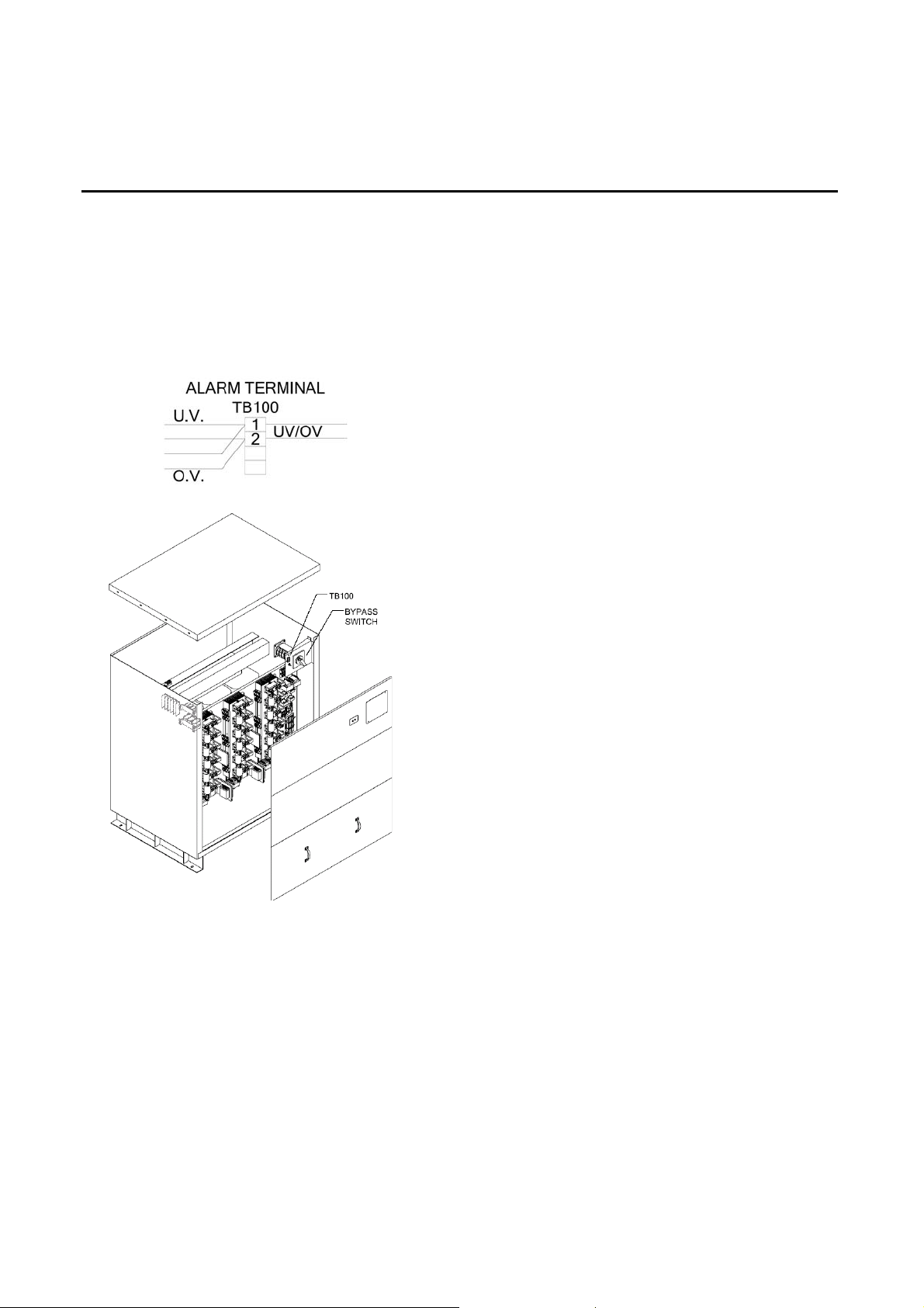
OnLine Power
K: DESCRIPTION:
POWER MONITOR RELAY (Multifunction Voltage relay Bender part no. VMD421 H-D-3):
It will monitor Input-under voltage/phase loss, over voltage; for customer connection a Terminal Block
is provided. This terminal block (TB100) is located behind bypass switch panel and should be wired
per diagram below, wiring can be routed behind the Bypass switch panel and enter thru cut out above
the Terminal block.
6002-032 REV H B-
3
Page 86
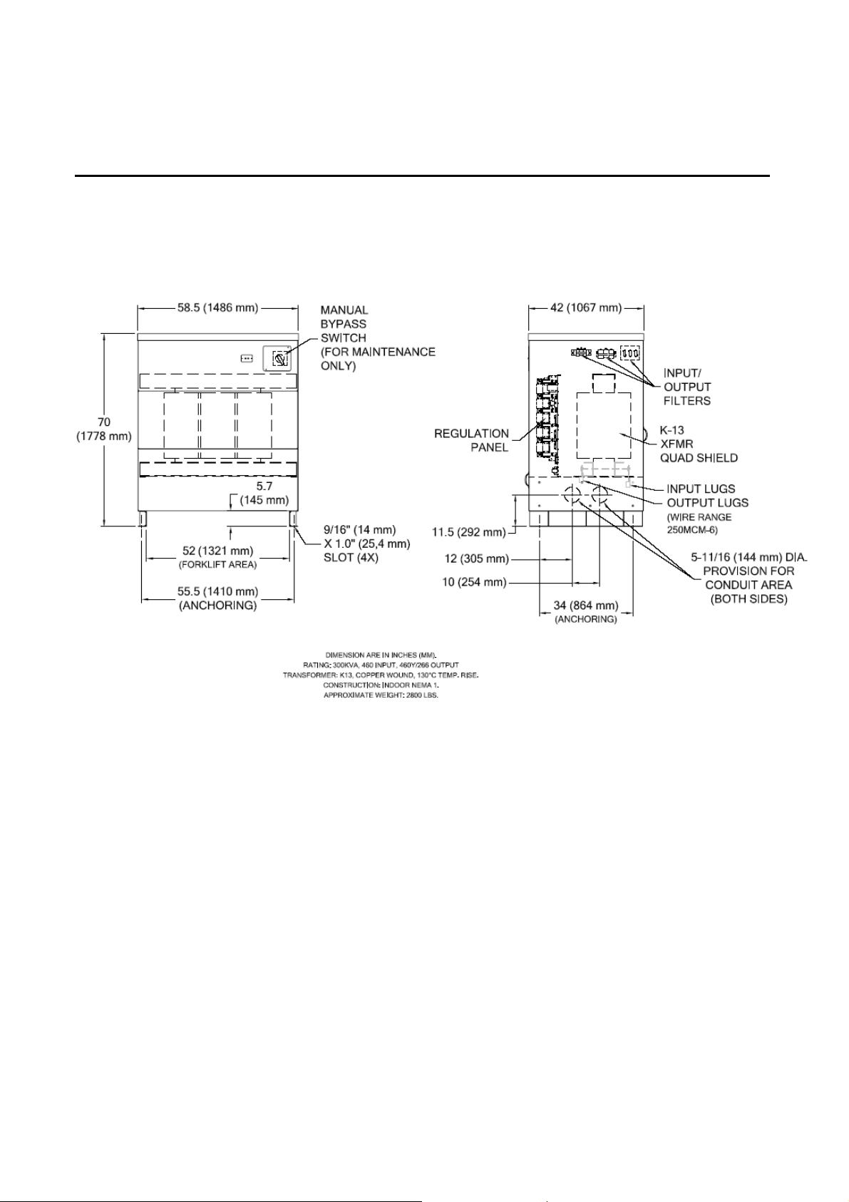
OnLine Power
INSTALLATION MOUNTING AND CABLE ENTRY
6002-032 REV H B-
4
Page 87
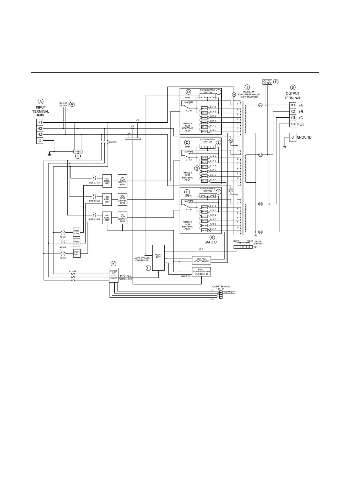
OnLine Power
BLOCK DIAGRAM B-1
6002-032 REV H B-
5
Page 88

OnLine Power
GLOSSARY
AC Air Conditioning
Current transformer The transformer used to feed a current signal to the logic board.
Front door The hinged front door on the CP 18 and Phase Stabilizer (15 - 75 KVA). It
covers the bypass switch and the IMCB if installed.
Front panel The hinged panel behind the front door on the CP 18 and Phase Stabilizer
(15 - 75 kVA) into which the bypass switch and the IMCB (if installed) are
mounted.
IMCB InputMain Circuit Breaker — The circuit breaker on the front panel used to switch
power to the CP 18 ON and OFF. Optional on Phase Stabilizer
(15 - 75 kVA).
NEC National Electric Code
NEMA National Electrical Manufacturers Association
OSHA Occupational Safety and Health Administration
PCB Printed Circuit Board — A surface for the mounting and interconnection of
electronic components.
REPO Remote Emergency Power Off — A switch, separate from but wired to the
regulation unit, when pressed, shunt trips the Main Input Circuit Breaker.
Thermal REPO Thermal Remote Emerg ency Power Off — A thermal activated switch, separate
from but wired to the regulation unit, which reacts to a predetermined
temperature range by shunt tripping the Main Input Circuit Breaker.
Reset (a circuit breaker) Snap the breaker first to OFF position, then to ON.
SCR Silicon-Controlled Rectifier
Shunt Trip A device for tripping a circuit breaker indirectly, using a signal to activate a
solenoid, instead of directly, because of an overcurrent condition.
Trip A circuit breaker in an open position as a result of an overcurrent condition to the
load, or as the result of a remote trip command (shunt trip). In a tripped
condition, power to the load is off. The tripped circuit breaker position differs
from the off position in that the breaker must first be turned to the off position
before restoring powe r to the load.
TB Terminal BlocK
6002-032 REV H G-1
 Loading...