

Page 1
ONLINE ELECTRONICS LTD
3014X ATEX EM TRANSMITTER MANUAL RevB00 Page 1 of 16
OPERATING MANUAL
CONFIGURATION INFORMATION
SERIAL NUMBER:
OUTPUT SIGNAL:
REPETITION RATE 1:
RATE 1 BATTERY LIFE AT +20°C:
REPETITION RATE 2:
RATE 2 BATTERY LIFE AT +20°C:
3014X ATEX
EM TRANSMITTER
Page 2

ONLINE ELECTRONICS LTD
3014X ATEX EM TRANSMITTER MANUAL RevB00 Page 3 of 16
CONTENTS Page
1. GENERAL DESCRIPTION ......................................................................................... 4
2. SPECIFICATIONS ................................................................................................... 5
3. OPERATION .......................................................................................................... 6
3.1. TURNING ON ..................................................................................................... 6
3.2. TURNING OFF ................................................................................................... 6
3.3. FUNCTION TEST ................................................................................................ 7
3.4. DEPLOYMENT .................................................................................................... 7
3.5. MODE SELECT ................................................................................................... 8
3.6. INSTALLATION .................................................................................................. 9
3.7. BATTERY LIFETIME .......................................................................................... 10
3.8. BATTERY REPLACEMENT ................................................................................... 11
3.9. LITHIUM BATTERY SAFETY ................................................................................ 12
4. MAINTENANCE .................................................................................................... 13
4.1. O-RING REPLACEMENT ..................................................................................... 13
4.2. ROUTINE MAINTENANCE AND STORAGE ............................................................. 14
5. DISPOSAL OF UNIT .............................................................................................. 15
6. WARRANTY ......................................................................................................... 15
7. APPENDIX A – ATEX SPECIFIC INSTRUCTIONS ........................................................ 16
Page 3
ONLINE ELECTRONICS LTD
3014X ATEX EM TRANSMITTER MANUAL RevB00 Page 4 of 16
1. GENERAL DESCRIPTION
The 3014X Electromagnetic transmitter is an ATEX certified EM transmitter that can be used
for pig tracking and location functions. The transmitter operates effectively in buried pipelines,
pipelines carrying gas and in pipeline bundles where acoustic transmitters are either less
effective or ineffective.
The transmitter emits a 21.8Hz signal and an inherent EM null spot is detectable when the EM
receiver antenna is at 90 degrees to and pointing at the centre of the transmitter allowing
centimetre accurate positioning of a pig.
The transmitter can be changed between two pulsing transmission rates via an easily
accessible slide switch inside the transmitter.
The transmitter is configured for use with Lithium batteries only. Lithium batteries provide a
significant improvement in battery lifetime and operation particularly at temperature extremes.
A non-ATEX version of the transmitter can be manufactured with specially designed endcaps
which allow fitting of pigging discs directly to the transmitter - the transmitter itself becomes
the pig body. This dramatically increases the received EM signal because it no longer needs to
propagate through an additional pig body as well as the pipeline.
Parameters such as lifetime, pulse rate, frequency, and output level can be customised during
manufacture, please contact Online Electronics Ltd for more details.
Page 4

ONLINE ELECTRONICS LTD
3014X ATEX EM TRANSMITTER MANUAL RevB00 Page 5 of 16
2. SPECIFICATIONS
NOTE THAT THE SPECIFICATIONS BELOW ARE VALID FOR THE STANDARD
CONFIGURATION ONLY. REFER TO THE COVER OF THIS MANUAL FOR THE
CONFIGURATION INFORMATION SPECIFIC TO THE TRANSMITTER BEING USED.
GENERAL:
Lifetime in continuous mode at +20°C in air .......................................................... 6.5 days
Lifetime pulsing 0.4sec ON / 0.6sec OFF at +20°C in air ........................................... 14 days
Lifetime pulsing 0.4sec ON / 1.6sec OFF at +20°C in air ............................................ 25 days
Lifetime pulsing 0.4sec ON / 2.6sec OFF at +20°C in air ........................................... 36 days
Lifetime pulsing 0.4sec ON / 3.6sec OFF at +20°C in air ........................................... 46 days
Lifetime pulsing 0.4sec ON / 4.6sec OFF at +20°C in air ........................................... 54 days
Lithium batteries .............................. 2x ELECTROCHEM 3B0035-TC PRIMARY LITHIUM D CELL
Standard signal at 1m with OEL reference antenna at +20°C in air ........................... 185mVpp
Standard frequency ............................................................................................... 21.8Hz
Operating temperature range ......................................................................... -40 to +80°C
External pressure rating ......................................................................................... 225bar
Bump rating.............................................................................................................. 20G
Typical weight including batteries .............................................................................. 3.5kg
MATERIALS:
Housing material .............................................................. 316 STAINLESS STEEL EN 1.4401
Endcap material ................................................................ ALLOY BRONZE CA104 EN 12163
Bleedscrew material .......................................................... 316 STAINLESS STEEL EN 1.4401
O-rings ............................................................... NBR70 (standard) / FKM936 (heavy duty)
ATEX:
Notified body number................................................................................................ 0891
Type examination number ............................................................... TRAC 09 ATEX 21218 X
Code ......................................................................................... Ex II 2 G Ex d IIB T4..T6X
Page 5

ONLINE ELECTRONICS LTD
3014X ATEX EM TRANSMITTER MANUAL RevB00 Page 6 of 16
3. OPERATION
THE SPECIAL CONDITIONS FOR SAFE USE DETAILED IN SECTION 7 APPENDIX A –
ATEX SPECIFIC INSTRUCTIONS OF THIS MANUAL MUST BE OBSERVED AND
FOLLOWED AT ALL TIMES
WARNING 1 – THE TRANSMITTER SHOULD ONLY BE OPENED IN A CLEAN, DRY,
LABORATORY ENVIRONMENT.
WARNING 2 – TO PREVENT THE FORMATION OF CONDENSATION WITHIN THE
TRANSMITTER ALLOW THE TRANSMITTER TEMPERATURE TO STABILISE WITHIN THE
LABORATORY ENVIRONMENT FOR A MINIMUM OF 6 HOURS PRIOR TO OPENING.
WARNING 3 – IF THE TRANSMITTER IS BEING OPENED FOR THE FIRST TIME AFTER
IMMERSION IN PIPELINE PRODUCTS THEN EXPECT SOME LIQUID TO BE PRESENT
WITHIN THE ENDCAP THREADS. CARE SHOULD BE TAKEN WHEN OPENING THE UNIT
TO ALLOW ANY LIQUID TO DRAIN OUT OF AND NOT IN TO THE TRANSMITTER.
WARNING 4 – REPLACE ALL BATTERIES AT THE SAME TIME. NEVER USE A MIX OF
NEW AND USED BATTERIES. NEVER USE A MIX OF BATTERIES FROM DIFFERENT
BATCHES. USE ONLY ELECTROCHEM 3B0035-TC LITHIUM D CELLS. ALWAYS OBSERVE
CORRECT BATTERY POLARITY AND USE OF THE BATTERY DISC. REFER TO SECTION
3.9 LITHIUM BATTERY SAFETY FOR FURTHER INFORMATION.
WARNING 5 – IF THE TRANSMITTER IS TO BE PLACED IN STORAGE ALWAYS ENSURE
THAT IT IS TURNED OFF AND THE BATTERIES REMOVED AND STORED SEPARATELY.
3.1. TURNING ON
1. Familiarise yourself with all warnings given at the start of Section 3 OPERATION.
2. To turn the transmitter on, fully tighten the bleed screw using a 10mm AF Allen key. Do
not use excessive torque. The transmitter takes approximately 5 seconds to turn on. Note
that the transmitter is usually shipped with a Nylon washer under the bleed screw to
prevent accidental activation during transport. This must be removed before the
transmitter can be turned on.
3. Use an EM receiver system to confirm that the transmitter is functioning properly at the
expected pulse rate.
3.2. TURNING OFF
1. Familiarise yourself with all warnings given at the start of Section 3 OPERATION.
2. To turn the transmitter off, loosen the bleed screw 3 full turns using a 10mm AF Allen key.
To prevent the bleed screw being lost, or the transmitter accidentally being turned back
on, the bleed screw should be held in this position with some tape.
3. Use an EM receiver system to confirm that the transmitter has turned off.
Page 6

ONLINE ELECTRONICS LTD
3014X ATEX EM TRANSMITTER MANUAL RevB00 Page 7 of 16
3.3. FUNCTION TEST
An OEL EM receiver system is required to receive the signal from a 3014X transmitter. Refer to
the relevant EM receiver manual for instruction on setup and operation of the EM receiver
system.
1. Place the EM receiver antenna approximately 5m away and parallel to the transmitter.
2. Activate the transmitter as detailed in Section 3.1 TURNING ON.
3. Confirm that a clear signal is received.
4. Switch the transmitter between OFF, RATE 1 and RATE 2 several times to ensure that the
signal received reacts as expected. Refer to Section 3.5 MODE SELECT for further
information on changing transmission rates.
5. An inherent null spot is detectable when the antenna is at 90 degrees to and pointing at
the centre of the transmitter allowing accurate positioning of a pig. Refer to the relevant
EM receiver manual for further information.
6. Turn OFF the transmitter as detailed in Section 3.2 TURNING OFF.
7. If all results were as expected then the system is functional.
3.4. DEPLOYMENT
Before each deployment ensure that the following checks have been completed.
1. Ensure the transmitter has been installed as detailed in Section 3.6 INSTALLATION.
2. Visually inspect all system components to ensure that they are secure and undamaged.
3. Refer to the front cover of this manual for the expected battery lifetime and ensure that it
is adequate for the planned operations.
4. Activate the transmitter as detailed in Section 3.1 TURNING ON.
5. Complete a 3.3 FUNCTION TEST.
Page 7

ONLINE ELECTRONICS LTD
3014X ATEX EM TRANSMITTER MANUAL RevB00 Page 8 of 16
3.5. MODE SELECT
1. Familiarise yourself with all warnings given at the start of Section 3 OPERATION.
2. If not already loosened, using a 10mm AF Allen key, loosen the bleed screw 3 full turns to
release any internal pressure and to turn the transmitter off. There is no need to fully
remove the bleed screw. If you do so it may be lost.
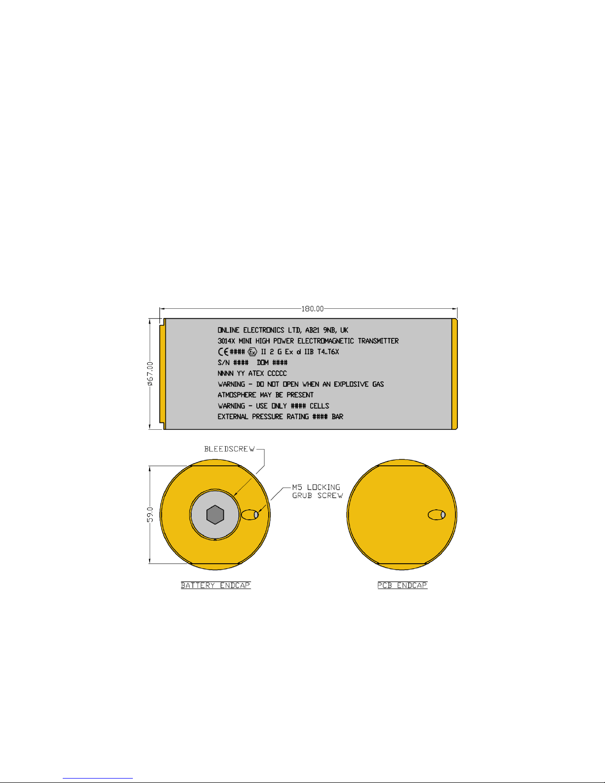
3. Using a 2.5mm AF Allen key fully unscrew the M5 locking grub screw on the PCB ENDCAP.
The grub screw may be screwed back in 3 turns to prevent it getting lost.
4. Using the supplied ENDCAP REMOVAL TOOL, fully remove the PCB ENDCAP to reveal the
PCB assembly and switch as shown in the figure below.
5. Set the MODE SWITCH to the desired position. The switch can be set to either RATE 1
(switch in upper position or PULS on older units) or RATE 2 (switch in lower position or
CONT on older units). Refer to the cover of this manual for the rates available from the
transmitter being used.
6. Examine the O-ring seals for any signs of contamination or damage, replace and/or re-
grease if necessary.
7. Replace the PCB ENDCAP using the supplied ENDCAP REMOVAL TOOL. Do not use a vice or
spanner, it only needs to be hand tight. Damage may occur if over tightened.
8. Tighten the M5 grub screw (until the grub screw engages with the housing to lock the PCB
ENDCAP). Note that very little torque is required. Damage may occur if over tightened.
9. Fully tighten the bleed screw to turn on the transmitter. Use an EM receiver system to
confirm transmitter function and correct transmission rate.
10. If the transmitter is not to be used immediately after the mode has been selected, loosen
the bleed screw 3 full turns to switch the transmitter off and use some tape to hold the
bleed screw in this position to prevent it being lost or the transmitter being accidentally
turned back on.
Page 8
ONLINE ELECTRONICS LTD
3014X ATEX EM TRANSMITTER MANUAL RevB00 Page 9 of 16
3.6. INSTALLATION
1. All EM transmitters will induce electrical currents in any conductive materials closely
surrounding them which can result in a severe reduction in signal strength and/or battery
lifetime. This effect can be minimised by reducing the amount of conducting material
surrounding the transmitter. Leave as much of the transmitter exposed as possible. Any
slits or apertures which can be made in the surrounding material will help. Use materials
with as high resistance as possible. Non-conducting materials such as plastics will not
suffer from this effect. EM transmitters must not be surrounded by low resistance metals
such as aluminium (including tubes or mounting clamps) under any circumstances.
2. Any magnetic material surrounding the transmitter will tend to block the EM signal from
the transmitter and reduce the received signal strength outside the pipeline. This effect can
be minimised by reducing the amount of magnetic material surrounding the transmitter.
Leave as much of the transmitter exposed as possible. Any slits or apertures which can be
made in the surrounding material will help. Use materials with as low magnetic
permeability as possible. Non-magnetic materials such as plastics will not suffer from this
effect.
3. The transmitter must be mounted in such a way that no movement or vibration
whatsoever is possible (e.g. clamped). If the transmitter is allowed to rattle and/or vibrate
within the pig then the resultant hammering effect can exceed the bump rating of the
transmitter leading to damage and/or failure. This is particularly important in gas pipelines.
For optimum performance the transmitter should be clamped inside a plastic pig body or
plastic guide discs should be clamped around the transmitter to form a pig. The advantage of
these methods is the fact that there is no metal around the transmitter apart from the pipeline
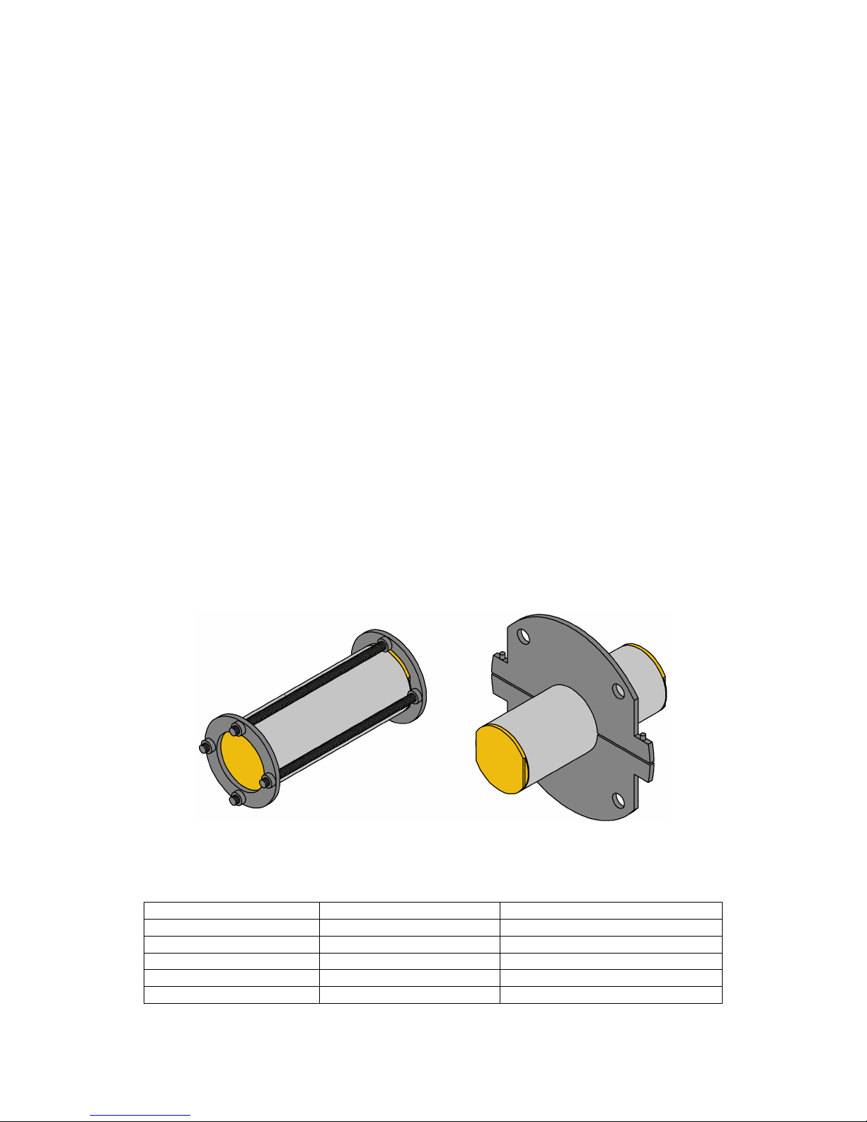
itself. Two alternative mounting arrangements are shown below. The first uses several lengths
of threaded studding to clamp the transmitter between two plates. The second uses a clamping
disc. The advantage of these arrangements is that they have limited amounts of metal around
the transmitter and will therefore have limited effect on the transmitter performance. Please
contact Online Electronics for further information and guidelines regarding EM transmitter
mounting and installation.
The table below shows the typical characteristics of several potential pig and mounting
materials with the best choice at the top, and the worst choice at the bottom. 316 stainless
steel provides a good balance of properties and cost. An aluminium alloy would be a very poor
choice because of the very low resistivity and should not be used under any circumstances.
MATERIAL
RESISTIVITY (µΩ.m)
MAGNETIC PERMEABILITY
PLASTIC ∞ 1.000
316 STAINLESS STEEL
0.75
1.008
2205 DUPLEX SS
0.80
>25.0
1005 STEEL
0.20
>100
ALUMINIUM ALLOYS
0.04
1.000
Page 9
ONLINE ELECTRONICS LTD
3014X ATEX EM TRANSMITTER MANUAL RevB00 Page 10 of 16
3.7. BATTERY LIFETIME
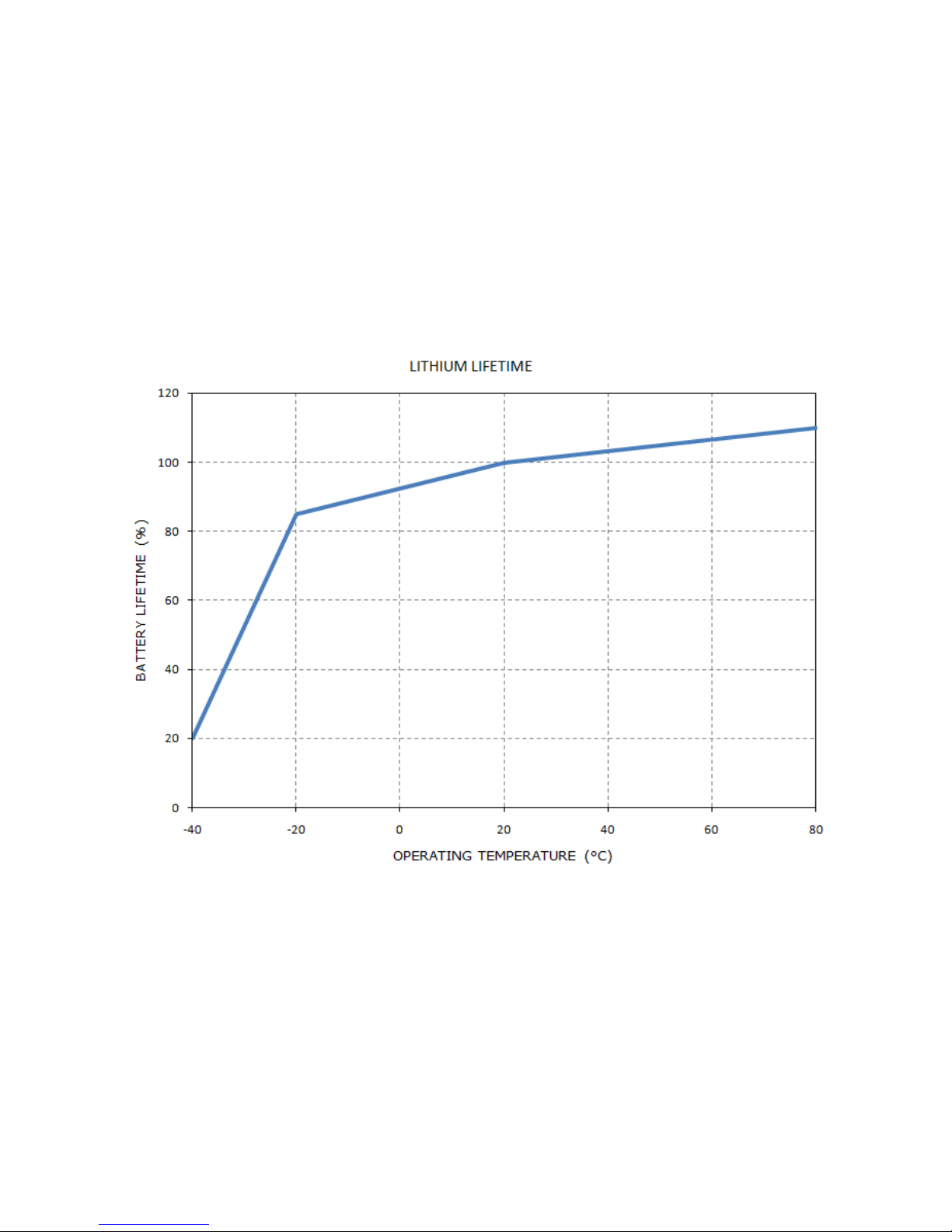
The operating temperature which the transmitter is used at alters the operating lifetime.
Typically colder temperatures will shorten the stated lifetime as shown by the figure below.
Note that upon customer request, the transmitters can be adjusted at Online Electronics Ltd to
provide a stronger signal at the expense of lifetime or extended lifetime at the expense of
signal, contact Online Electronics Ltd for more details and to discuss your requirements.
In extreme circumstances the transmitter operating lifetime may be reduced by how the
transmitter is installed on a pig. For example, if it is installed inside an aluminium tube, the
operating lifetime may be reduced to as little as 50%. Refer to Section 3.6 INSTALLATION
within this manual for tips on how to achieve optimum performance from the transmitter with
regards to the mounting arrangement.
Page 10
ONLINE ELECTRONICS LTD
3014X ATEX EM TRANSMITTER MANUAL RevB00 Page 11 of 16
3.8. BATTERY REPLACEMENT
1. Familiarise yourself with all of the warnings given at the start of Section 3 OPERATION.
2. Using a 10mm AF Allen key loosen the bleed screw 3 full turns to release any internal
pressure and to turn the transmitter off. There is no need to fully remove the bleed screw.
If you do so it may be lost.
3. Using a 2.5mm AF Allen key fully unscrew the M5 locking grub screw on the BATTERY
ENDCAP. The grub screw may be screwed back in 3 turns to prevent it getting lost.
4. Using the supplied ENDCAP REMOVAL TOOL, fully remove the BATTERY ENDCAP.
5. Remove all ELECTROCHEM 3B0035-TC Lithium cells and the battery disc. Visually inspect
the batteries, contact Online Electronics Ltd immediately if there are any signs of damage
or electrolyte leakage. Dispose of the old batteries in a responsible way. Refer to section
3.9 LITHIUM BATTERY SAFETY for further guidance. Place the battery disc safely to one
side so it doesn’t get lost.
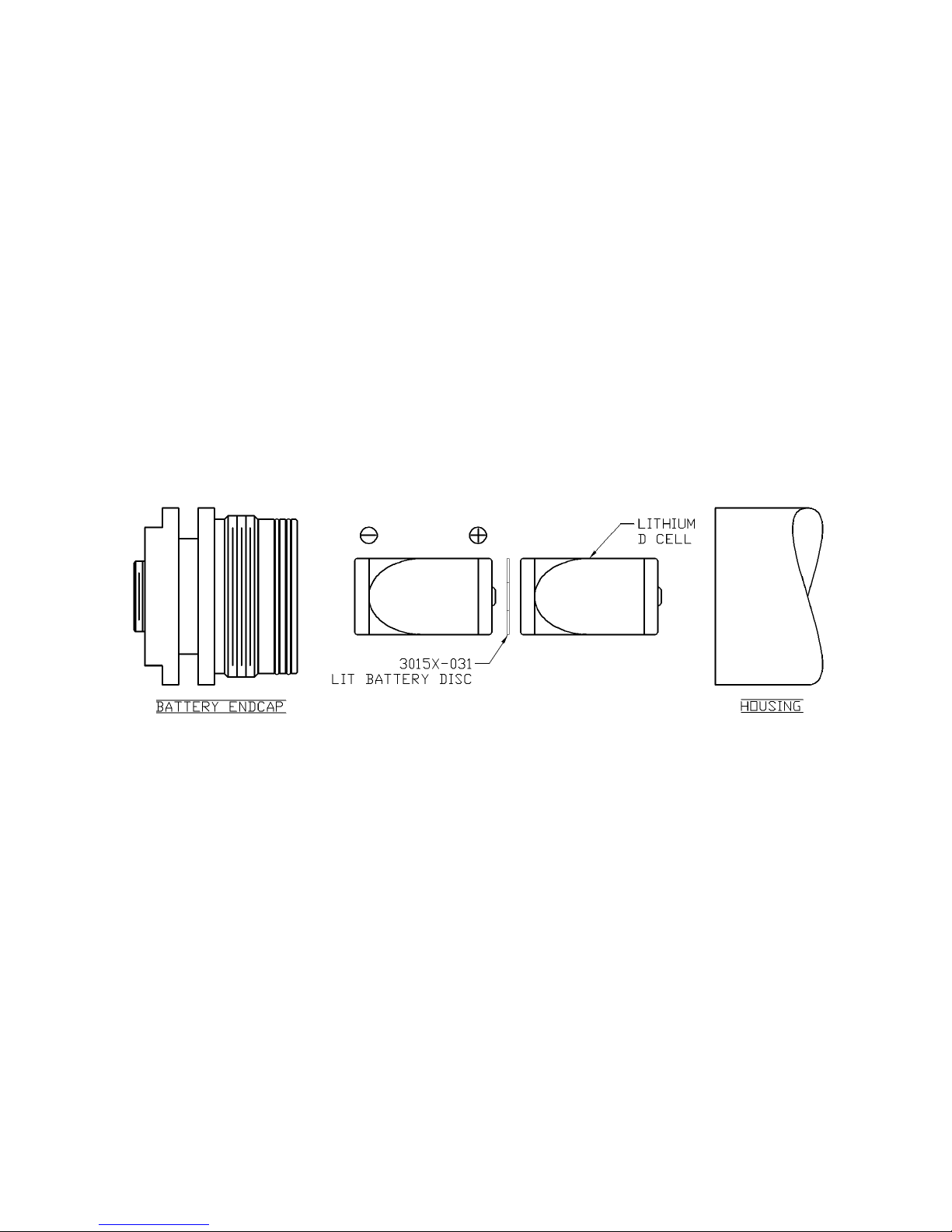
6. Observing the battery polarity shown in the figure below, insert 2x new ELECTROCHEM
3B0035-TC Lithium D cells into the battery compartment POSITIVE END first with a 3015X031 LIT BATTERY DISC between neighbouring cells. A total of 1x battery disc will be
required.
7. Once all batteries are installed ensure that it is the FLAT, NEGATIVE END of the batteries
which you see when looking into the open end of the transmitter.
8. Examine the O-ring seals for any signs of contamination or damage, replace and/or re-
grease if necessary.
9. Replace the BATTERY ENDCAP using the supplied ENDCAP REMOVAL TOOL. Do not use a
vice or spanner, it only needs to be hand tight. Damage may occur if over tightened.
10. Tighten the M5 grub screw (until the grub screw engages with the housing to lock the
BATTERY ENDCAP). Note that very little torque is required. Damage may occur if over
tightened.
11. Fully tighten the bleed screw to turn on the transmitter. Using an EM receiver, confirm
transmitter function and correct transmission rate.
12. If the transmitter is not to be used immediately after battery replacement, loosen the
bleed screw 3 full turns to switch the transmitter off and use some tape to hold the bleed
screw in this position to prevent it being lost or the transmitter being accidentally turned
back on.
Page 11

ONLINE ELECTRONICS LTD
3014X ATEX EM TRANSMITTER MANUAL RevB00 Page 12 of 16
3.9. LITHIUM BATTERY SAFETY
The information given in this section is for reference only. It should not be used in
place of appropriate local regulations or other legal requirements. Online Electronics
Ltd are not responsible for any incident that occurs due to misuse or abuse of their
products or misuse or abuse of lithium cells used by their products.
The batteries used in this transmitter have a very high energy density giving the transmitter a
superior lifetime. However, the same properties which result in a high energy density also
contribute to potential hazards if the energy is released at a fast, uncontrolled rate. With
proper use and handling, ELECTROCHEM cells have demonstrated an excellent safety record in
applications where safety and reliability is of utmost importance.
Because of the recognition of hazards associated with high energy density systems, safety has
been incorporated into the design and manufacture of ELECTROCHEM cells and the Online
Electronics Ltd transmitter. While the transmitter and cells have been designed to be tolerant
to adverse conditions, there are limitations. In particular, the transmitter and cells must be
protected from excessive heat and excessive mechanical abuse. The cells have warnings
printed on their label that cautions against the following conditions:
Short circuit
Charge
Forced over discharge
Excessive heating or incineration
Crush, puncture or disassembly
Rough handling or excessive shock and vibration
Not guarding against these conditions may result in a hot cell that could either vent or explode
at the instant of abuse, or, more typically, the cell shall heat up over a period of time and
subsequently vent or explode when its critical temperature is reached. Problems associated
with hazardous conditions can be greatly reduced by observing the following guidelines:
When handling the transmitter:
Never drop the transmitter. This may damage the cells inside. If dropped, the
cells should be replaced. During operation observe the shock and vibration limits given.
Never store or operate the transmitter outside its operating temperature range.
Always replace all batteries at the same time. Replace with NEW batteries from
the SAME batch. This will help to prevent over discharge of individual cells.
Always observe correct battery polarity when replacing batteries.
When handling loose cells:
Cover all metal work surfaces with an insulating material
The work area should be clean and free of sharp objects that could puncture the
insulating sleeve on each cell
Personnel handling cells should remove all jewellery that could come into contact
with battery terminals
Never stack or scatter loose cells. They should be placed in insulating carrying
trays with individual compartments for each cell.
Cells should be inspected for physical damage, possibly caused by dropping.
Cells with dented cases or terminal caps should be disposed of in a responsible manner.
Measure the Open Circuit Voltage (OCV) of cells. The nominal OCV is 3.9V. An
open circuit voltage of 0.0V is indicative of a blown internal fuse.
The cells must never be disassembled.
REFERENCE: http://www.electrochemsolutions.com/pdf/Safety_and_Handling_Guide.pdf
Page 12
ONLINE ELECTRONICS LTD
3014X ATEX EM TRANSMITTER MANUAL RevB00 Page 13 of 16
4. MAINTENANCE
THE SPECIAL CONDITIONS FOR SAFE USE DETAILED IN SECTION 7 APPENDIX A –
ATEX SPECIFIC INSTRUCTIONS OF THIS MANUAL MUST BE OBSERVED AND
FOLLOWED AT ALL TIMES.
WARNING 1 – THE TRANSMITTER SHOULD ONLY BE OPENED IN A CLEAN, DRY,
LABORATORY ENVIRONMENT.
WARNING 2 – TO PREVENT THE FORMATION OF CONDENSATION WITHIN THE
TRANSMITTER ALLOW THE TRANSMITTER TEMPERATURE TO STABILISE WITHIN THE
LABORATORY ENVIRONMENT FOR A MINIMUM OF 6 HOURS PRIOR TO OPENING.
WARNING 3 – IF THE TRANSMITTER IS BEING OPENED FOR THE FIRST TIME AFTER
IMMERSION IN PIPELINE PRODUCTS THEN EXPECT SOME LIQUID TO BE PRESENT
WITHIN THE ENDCAP THREADS. CARE SHOULD BE TAKEN WHEN OPENING THE UNIT
TO ALLOW ANY LIQUID TO DRAIN OUT OF AND NOT IN TO THE TRANSMITTER.
WARNING 4 – REPLACE ALL BATTERIES AT THE SAME TIME. NEVER USE A MIX OF
NEW AND USED BATTERIES. NEVER USE A MIX OF BATTERIES FROM DIFFERENT
BATCHES. USE ONLY ELECTROCHEM 3B0035-TC D CELLS. ALWAYS OBSERVE CORRECT
BATTERY POLARITY AND USE OF BATTERY DISCS. REFER TO SECTION 3.9 LITHIUM
BATTERY SAFETY FOR FURTHER INFORMATION.
WARNING 5 – IF THE TRANSMITTER IS TO BE PLACED IN STORAGE ALWAYS ENSURE
THAT IT IS TURNED OFF AND THE BATTERIES REMOVED AND STORED SEPARATELY.
4.1. O-RING REPLACEMENT
1. Familiarise yourself with all of the warnings given at the start of Section 4 MAINTENANCE.
2. Using a 10mm AF Allen key fully remove the bleed screw.
3. Using a 2.5mm AF Allen key fully unscrew the M5 locking grub screw on the PCB and
BATTERY ENDCAPS. The grub screws may be screwed back in 3 turns to prevent them
getting lost.
4. Using the supplied ENDCAP REMOVAL TOOL, fully remove the BATTERY ENDCAP, any
batteries and the battery disc, then the PCB ENDCAP.
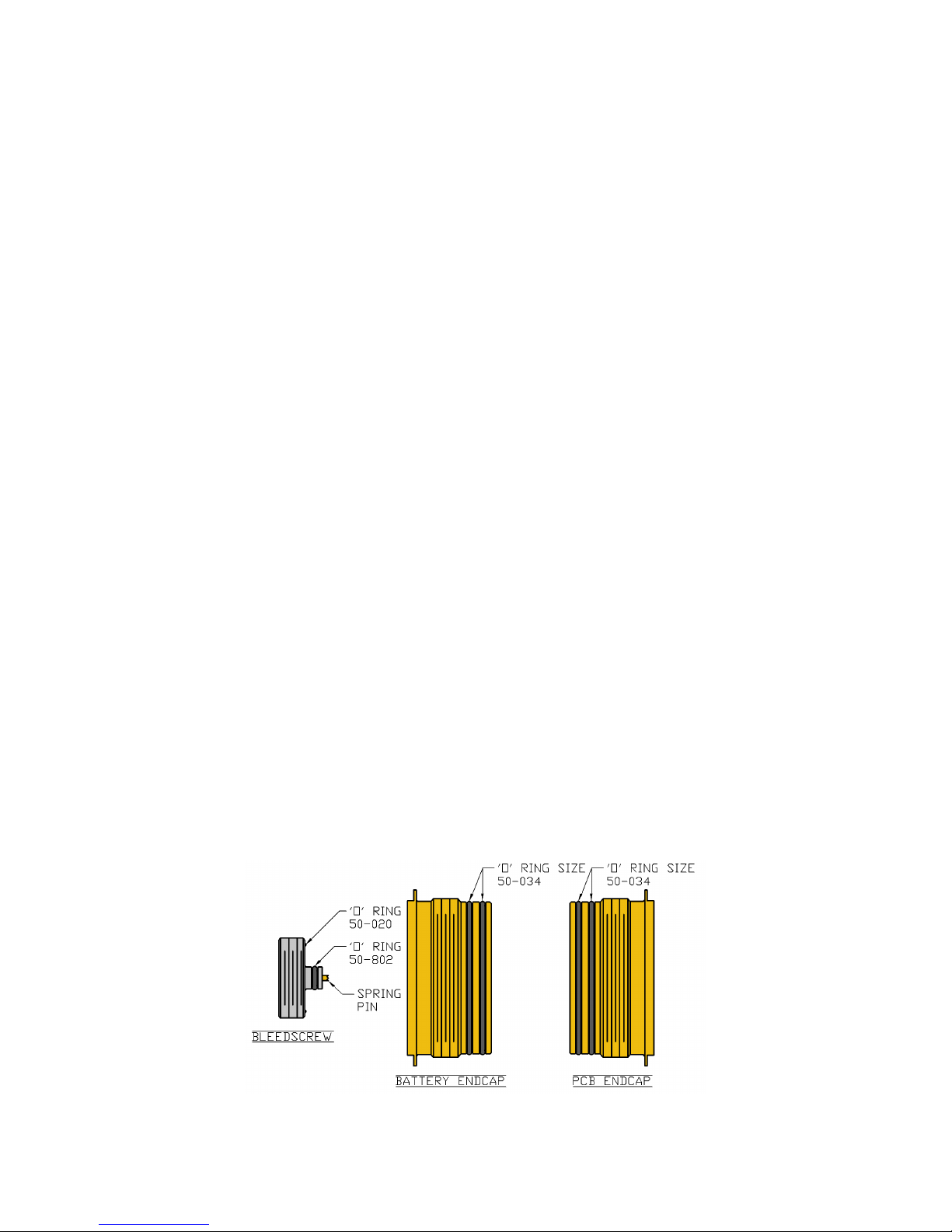
5. Referring to the figure below, remove all O-rings and clean the sealing surfaces on all
parts.
Page 13

ONLINE ELECTRONICS LTD
3014X ATEX EM TRANSMITTER MANUAL RevB00 Page 14 of 16
6. Examine all surfaces for signs of corrosion, scoring and other damage. If there is excessive
damage the mechanical parts may need to be replaced.
7. Lightly grease all sealing surfaces using a suitable grease (e.g. DOW CORNING MOLYKOTE
111 COMPOUND).
8. Lightly grease each O-ring with a suitable grease (e.g. DOW CORNING MOLYKOTE 111
COMPOUND) before fitting.
9. Referring to Section 3.8 BATTERY REPLACEMENT re-insert the batteries and the battery
disc, then refit the BATTERY ENDCAP to the BATTERY end of the housing and the PCB
ENDCAP to the PCB end of the housing using the ENDCAP REMOVAL TOOL. Do not use a
vice or spanner, the endcaps only need to be hand tight.
10. Tighten the M5 grub screw on each ENDCAP (until the grub screw engages with the
housing to lock each endcap in place). Note that very little torque is required. Damage
may occur if over tightened.
11. Examine the bleedscrew spring pin for any signs of damage, ensure it is not stuck and has
a smooth travel of approximately 3mm. Fully tighten the bleed screw then loosen 3 full
turns to ensure the transmitter is turned off and use some tape to hold the bleed screw in
this position and prevent it being lost or the transmitter being accidentally turned back on.
4.2. ROUTINE MAINTENANCE AND STORAGE
All Online Electronics Ltd transmitters are designed to require minimum maintenance. The
housing should be cleaned using fresh water and cleaning agents as necessary (e.g. WD40).
Do not use chemicals which could be damaging to the housing or ‘O-rings.
Check flame paths / threads on the enclosure body and lid for signs of corrosion or damage. If
badly pitted or damaged, replace the relevant component.
All components that are replaced must be in accordance with the manufacturers’ specifications.
Failure to use such components may invalidate the certification/approval and may make the
equipment dangerous.
Online Electronics Ltd can supply redress kits containing a complete set of replacement
batteries, battery discs, O-rings, O-ring grease, and endcap locking screws, contact Online
Electronics Ltd for more information.
If the transmitter is to be placed in storage for a long period of time remove the batteries and
battery disc from the transmitter and store separately. Refer to Section 3.9 LITHIUM BATTERY
SAFETY for further guidance.
As a minimum the bleed screw must be loosened 3 full turns to switch the transmitter off.
The Transmitter is shipped with a nylon washer underneath the bleed screw to prevent the unit
being accidentally switched on in transit. This washer must be removed before the transmitter
can be turned on.
Page 14

ONLINE ELECTRONICS LTD
3014X ATEX EM TRANSMITTER MANUAL RevB00 Page 15 of 16
5. DISPOSAL OF UNIT
Online Electronics Ltd (OEL) takes its responsibilities under the WEEE Regulations extremely
seriously and has taken steps to be compliant in line with our corporate and social
responsibilities. In the UK, OEL has joined a registered compliance scheme WeeeCare
(registration number WEE/MP3538PZ/SCH).
Electrical and electronic equipment should never be disposed of with general waste but must
be separately collected for the proper treatment and recovery.
The crossed out bin symbol, placed on the product, reminds you of the need to dispose of it
correctly at the end of its life.
When buying a new product you will have the possibility to return, free of charge, another end
of life product of equivalent type that has fulfilled the same functions as the su pplied
equipment. These items may be deposited at:
Online Electronics Ltd
Online House
266 Auchmill Road
Aberdeen
AB21 9NB
UK
Alternatively, to arrange a collection of any waste electrical equipment, obligated to OEL please
telephone WeeeCare on 0844 800 2004.
6. WARRANTY
Online products are guaranteed for one year from the date of purchase. Goods should be
returned transportation prepaid to Online Electronics Limited, 266 Auchmill Road, Aberdeen.
There is no charge for parts or labour should any product require repair due to a
manufacturing deficiency during the guarantee period.
In the event of a manufacturing deficiency the inward transportation costs will be repaid to the
client.
Page 15

ONLINE ELECTRONICS LTD
3014X ATEX EM TRANSMITTER MANUAL RevB00 Page 16 of 16
7. APPENDIX A – ATEX SPECIFIC INSTRUCTIONS
MANUFACTURER: Online Electronics Ltd
Online House
266 Auchmill Road
Aberdeen
AB21 9NB
Tel: +44 (0) 1224 714 714
Fax: +44 (0) 1224 710 101
Web: www.online-electronics.com
NOTIFIED BODY NUMBER: 0891
TYPE EXAMINATION No: TRAC 09 ATEX 21218 X
SPECIAL CONDITIONS FOR SAFE USE:
1. Temperature class is reliant on the operating ambient temperature as follows:
2. Warning – Do not open when an explosive atmosphere may be present.
3. Only ELECTROCHEM 3B0035-TC cells are permitted to be used in this equipment.
ATEX DIRECTIVE CODE: II 2 G
STANDARDS CODE: Ex d IIB T4..T6X
Ambient Temperature
T Class
-40°C to +40°C
T6
-40°C to +80°C
T4
 Loading...