

Online Doggy Home buddies cam User Manual
User Manual
Online Doggy – 4720 South Santa Fe Circle, Englewood, CO 80110
Revision: 1.06
Date: 05/14/2009

Fixed Wireless/Wired IP Camera
Table of Contents
LIST OF FIGURES AND TABLES..................................................................................... ...4
1. INTRODUCTION........................................................................................................ ..6
2. HARDWARE DESCRIPTION AND QUICK INSTALLATION/USAGE .............................7
2.1. MAJOR HARDWARE COMPONENTS. .. ..................................................... ...7
2.2. QUICK INSTALLATION AND USAGE .............................................................8
2.3. WIRELESS CONNECTION (FOR IP CAM(W)) ............................................. .12
3. WEB CONFIGURATIONS........................................................................................ ..14
3.1. INFORMATION ........................................................................................... .15
3.2. VIDEO DISPLAY .......................................................................................... .16
3.3. NETWORK ................................................................................................... .17
3.4. WIFI SECURITY (FOR IP CAM(W)) ................................................................19
3.5. ADVANCED NETWORK... .............................................................................21
3.6. VIDEO SETTINGS ... .................................................................................... ..22
3.7. 3GPP/RTSP SETTINGS ...................................................................................24
3.8. MOTION DETECTION... .................................................................................25
3.9. LED DISPLAY CONTROL ...............................................................................27
3.10. DATE/TIME.....................................................................................................28
3.11. ADMIN ... .................................................................................................... .29
3.12. UPGRADE ................................................................................................... .30
3.13. REBOOT....................................................................................................... .31
3.14. SAFE MODE ................................................................................................332
3.15. SET TO FACTORY DEFAULT ... .................................................................... ..33
4. FEATURES AND SPECIFICATIONS ... ....................................................................... .34
4.1. FEATURES ......................................................................................................34
4.2. SPECIFICATIONS...........................................................................................35
5. PACKAGE CONTENTS ........................................................................................... ..37
APPENDIX A. LIST OF TESTED NAT/ROUTER DEVICES ............................................... ..38
APPENDIX B. MAXIMUM ALLOWED VIDEO USERS... ................................................ ..39
APPENDIX C. PERFORMANCE INFORMATION ... ...................................................... .40
APPENDIX D. TROUBLE SHOOTING .......................................................................... ..41
APPENDIX E. 3GPP/ISMA OPERATION ...................................................................... .43
2

Fixed Wireless/Wired IP Camera
APPENDIX F. THIRD PARTY AND EMBEDDED WEB PAGE INTEGRATION .................. ...44
3

Fixed Wireless/Wired IP Camera
List of Figures and Tables
Figure 2-1: Major components in the front panel
Figure 2-2: Major components in the back panel
Figure 2-3: IP CAM connection diagram.
Figure 2-4: Connect Ethernet cable to a switch/router.
Figure 2-5: The installation CD disk
Figure 2-6: The ID/Password card
Figure 2-7: Running window of CamView program
Figure 2-8: Pop-up play-video password window
Figure 2-9: Unplug the Ethernet cable to enable the WiFi function
Figure 3-1: Open the web configuration page from CamView software
Figure 3-2: IP CAM Web configuration login page
Figure 3-3: IP CAM Information page
Figure 3-4: Video display page
Figure 3-5: Network settings page for DHCP function
Figure 3-6: Network settings page for fixed IP address
Figure 3-7: WiFi security disabled page
Figure 3-8: WiFi security enabled page
Figure 3-9: WiFi testing page
Figure 3-10: Advanced network settings page
Figure 3-11: Video settings page
Figure 3-12: 3GPP/RTSP enabled page
Figure 3-13: Motion detection enabled page
Figure 3-14: Led Control settings page
Figure 3-15: System date/time settings page
Figure 3-16: Admin settings page
Figure 3-17: Firmware upgrade settings page
Figure 3-18: Firmware upgrade status page
Figure 3-19: System reboot settings page
Figure 3-20: System reboot under-going page
Figure 3-21: Safe mode information page
Figure 3-22: Stick the reset button to set to the factory default
Figure 5-1: IP Camera body
Figure 5-2: Power Adaptor
Figure 5-3: Bracket
Figure 5-4: Antenna
Figure 5-5: Quick installation guide
4

Fixed Wireless/Wired IP Camera
Figure 5-6: Ethernet cable
Figure 5-7: Installation CD
Figure 5-8: ID/Password Card
Table A-1: List of tested Wireless AP/router devices
Table A-2: List of tested Wired NAT/router devices
5

Fixed Wireless/Wired IP Camera
1. Introduction
The IP Cam/w is designed with the “user-friendly” idea deep in mind. The user
install the IP Cam/w easily on his/her home network and then access the IP
anywhere in the world through the accompanied video management software
CamView program without setting some complicated DNS name or changing the
router’s settings. It’s just a plug & play action.
For indoor surveillance and remote monitoring, the IP Cam/w provides the best
image quality in its class, and excellent performance. The IP Cam/w also provides the
best bandwidth efficiency, it offers 640x480 resolution, 30 fps frame rate, real MPEG4
image compression ability. The built-in microphone enables remote users to not only
view, but also listen for additional monitoring options.
Of course, with the built-in Web server, the IP Cameras can also be managed
from a standard web browser on a Windows computer.
The IP Cam(w) provides both wireless IEEE 802.11 b/g and wired Ethernet
network interfaces for flexible installation. It supports the WEP and WPA (Wi-Fi
Protected Access) security modes to provide the best security for wireless networks. (IP
Cam model only support wired Ethernet interface)
The IP Cam/w provides motion detection function. Users can easily setup this
function and receive the notification with the snapshot images through email and/or ftp
when some motion events are detected.
can
Camera
-
The IP Cam/w is ideal for securing small businesses, home offices and
residences over a local area network and/or the Internet.
The differences
It’s very easy to see the video of the IP Cam/w, you only need to key in the
ID/Password of the IP CAM anywhere in the world, you do not need to remember the IP
address or domain name or DDNS name or port number. And you do not need to modify
the settings (like port mapping, fixed IP, DDNS, virtual server) of the NAT/router devices, it’s
just a plug & play usage.
So, the differences are the followings:
♦ Public IP address needed ? No
♦ Dynamic DNS needed ? No
♦ Port mapping in router? No
♦ Virtual server in router ? No
♦ UPnP support in router ? No
♦ What’s needed ? ID and Password
6
Fixed Wireless/Wired IP Camera
2. Hardware description and quick installation/usage
The IP CAM is designed to be very easy to install and use. First, let’s see the major
components of the IP CAM products.
2.1. Major hardware components.
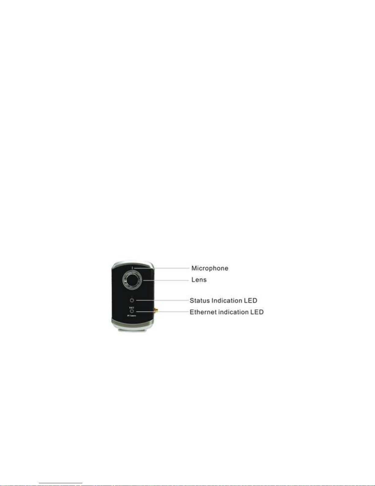
The major components on the
microphone, lens and LEDs :
1. Microphone - for receiving the audio/voice. Effective distance is about 5 meters.
2. Lens - the focus of the lens is fixed, you do not need to spend time to adjust the
focus, the effective focus range is from 40cm to infinity.
3. Status indication LED (red) - this LED is to indicate the Internet connection status.
When the Internet connection is connected, the LED will be constant red light. If
there is any Internet connection problem, the LED will be blinking red light.
4. Ethernet indication LED (blue) - this LED is to indicate if the Ethernet link is ok
and packet traffic is sending/receiving. When the Ethernet cable is connected, the
LED is constant blue light. When there is packet sending/receiving, the LED is
blinking blue light.
front panel
of the IP CAM products are the built-in
Figure 2-1: Major components in the front panel
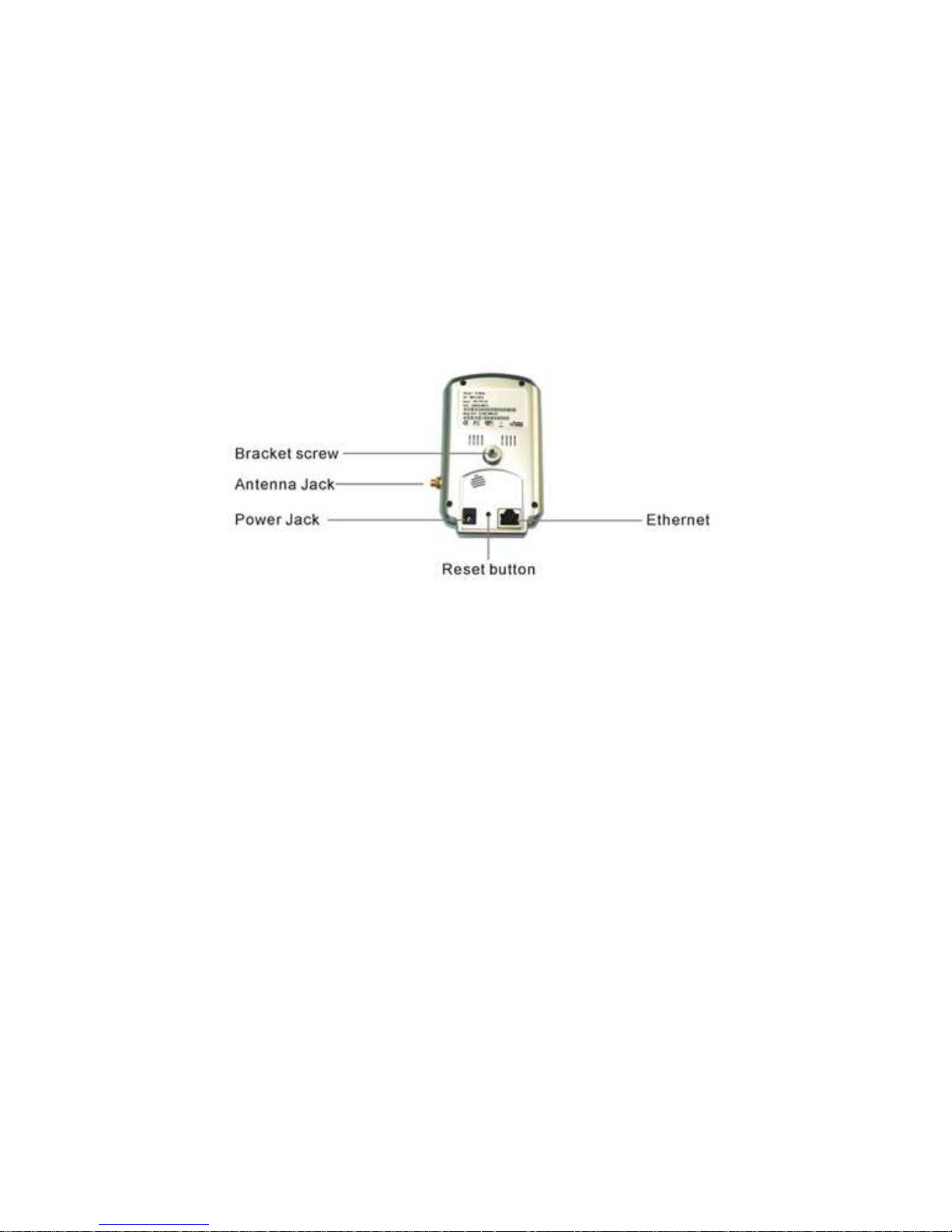
The major components on the
screw jack, power jack, Ethernet jack and reset button:
1. Bracket screw jack - this is the position to screw in the bracket of the IP CAM.
With the bracket, you can put the IP CAM on the desk, on the wall or on the
ceiling.
2. Power jack - this is the place to plug in the power adaptor. The power needed for
this IP CAM is 5V/1.0A, please make sure you are using the correct power
adaptor.
back panel
of the IP CAM products are the bracket
7
Fixed Wireless/Wired IP Camera
3. Ethernet jack - this is the place to plug in the RJ45 Ethernet cable. When the
Ethernet link is ok, the Ethernet indication LED on the front side will be blue light.
4. Reset button - this is the button to reset the IP CAM to default factory settings.
You need to use a small stick like pencil or tooth stick to press the reset button for
more than 3 seconds to enable the reset function. Usually when you forgot the
administrator account, you will probably need to do this reset action to reset to the
default factory settings. Please refer to section 3.15 for more details.
5. Antenna jack(for IP Cam(w)) - this is the place to hold the wireless antenna. The
antenna must be plugged to let the 802.11 b/g wireless work.
Figure 2-2: Major components in the back panel
2.2. Quick installation and usage
There are only three things that you need to do to see the video from the IP CAM.
1. Connect the IP CAM to the home/office network.
2. Install the CamView software on the notebook/PC.
3. Key in the ID/password of the IP CAM(from the IP/Password card) on the
CamView, and then you can see the video.
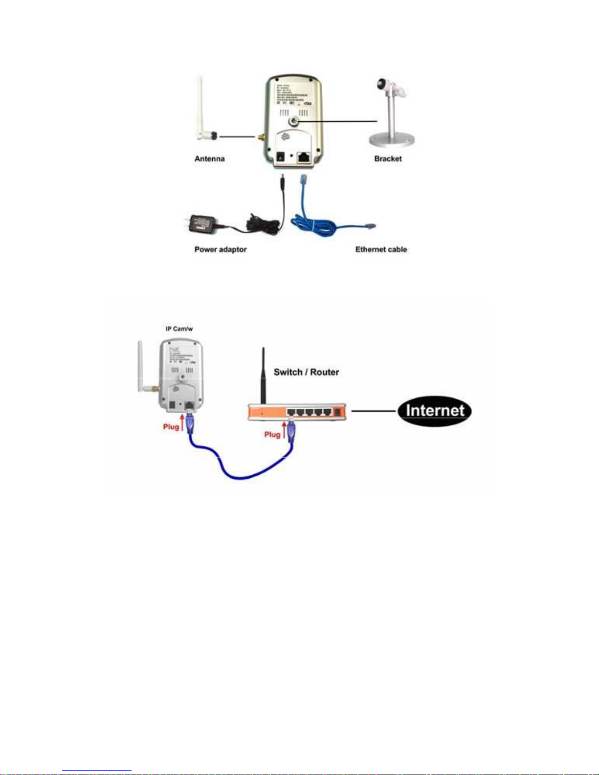
First, Connect the IP CAM to the home/office network
Please connect the IP CAM accessories to the IP CAM body correctly, including
the antenna, bracket, power adapter and Ethernet cable, as shown in Figure 2-3. And
connect the other end of the Ethernet cable to the home network or office network.
Usually, this Ethernet cable is plugged into a home NAT/router device or an Ethernet
switch if in the office, as shown in Figure 2-4. Since the default settings of the IP CAM
use DHCP function and very often there is a DHCP server on most of the Home/office
network, the IP CAM should be connected to the Internet immediately. The Internet
status LED is constant red light to indicate this good connection status. If the LED is
blinking, please refer to section 3.3~3.5 to try other network settings.
8
Fixed Wireless/Wired IP Camera
Figure 2-3: IP CAM connection diagram.
Figure 2-4: Connect Ethernet cable to a switch/router.
Second, Install the CamView software on the notebook/PC
Please insert the installation CD into the CD-ROM drive in your notebook or
personal computer (must be running Microsoft Windows OS). Execute the program
CamViewInstaller-xxx.exe on the disk. The program will pop-up some windows about
the installation options, please press the “next” button to proceed with the installation.
After the installation is complete, there will be a CamView icon on the desktop of your
computer screen, please execute this icon. The CamView program will run
immediately.
9

Fixed Wireless/Wired IP Camera
Figure 2-5: The installation CD disk
Third, Use CamView program to see the video
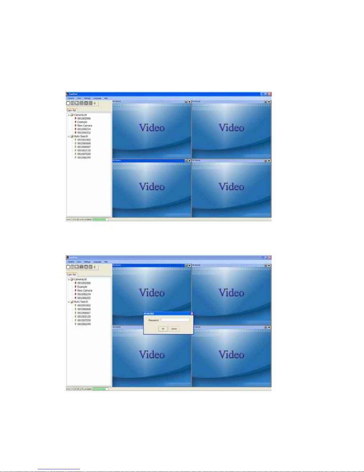
Figure 2-5 is the running window of the CamView program. If the computer and
IP CAM is connected to the same network, the IP CAM ID will be displayed in the
“Auto Search” list. You can double click the “Auto Search” to search all the connected
IP CAMs any time. The only thing left right now for seeing the video is to double click
the IP CAM ID item in the “Auto Search” list. For example, if the IP CAM ID is
001-001-029, you can then double click the 001001029 item in the “Auto Search” list
to view the video. A window asking for password input will pop up. Please key-in the
password in your ID/Password card into this field and click “ok”. The video will then be
displayed on the window.
Notice :
1. You can modify this play-video password by entering into the web configuration
pages. Please refer to section 3.6 for more information.
2. You can also add the IP CAM into the CameraList or GroupList in the CamView
software to have more convenient video display, please refer to the user manual
of the CamView software for more functions.
Seeing the video in a remote location
After the IP CAM is installed and you can see the video from the CamView
software in the local network, it’s very easy to see the video in a remote location. All
Figure 2-6: The ID/Password card
10
Fixed Wireless/Wired IP Camera
you need to do is add a camera item in the “CameraList” folder of the CamView
software, key in the IP CAM ID and Password(from the ID/Password card). And then
double click this camera item. You will then see the Camera video immediately. No
further NAT/router setting modifications are needed.
Figure 2-7: Running window of CamView program
Figure 2-8: Pop-up play-video password window
11

Fixed Wireless/Wired IP Camera
2.3. Wireless connection (for IP Cam(w))
The IP Cam(w) can also be connected to the home/office network through the
802.11 b/g wireless connection. There are only three things that you need to do to
have the wireless connection:
1. Set the WiFi security settings on the web configuration page.
2. Test if the WiFi settings are correct.
3. Unplug the Ethernet cable.
First, set the WiFi security settings on the web configuration page.
Make sure there is a WiFi router or AP on your home or office network. Write
down the WiFi security parameters used in this WiFi AP/router, including the SSID ,
security mode, encryption protocols and the “key” values. The supported WiFi security
mode of the IP CAM is WEP(64 bits and 128 bits) and WPA-PSK(TKIP and AES). In
most of the home/office WiFi environment, this is quite enough.
The easiest way to set the WiFi settings on the IP CAM is through CamView
software. Right-click the searched IP CAM in the “Auto Search” list and click the “Web
Configure” to open the login window of the IP CAM. Fill in all the WiFi security
parameters you have written down. The WiFi configuration is complete now.
Please refer to section 3.4 for more detailed description if needed.
Second, test if the WiFi settings are correct
You can now test if the above WiFi settings are correct. Click the “WiFi test” on
the “WiFi Security” settings web page. The testing result will be displayed in less than
60 seconds. If the test is failed, please check the WiFi security parameters and test
again.
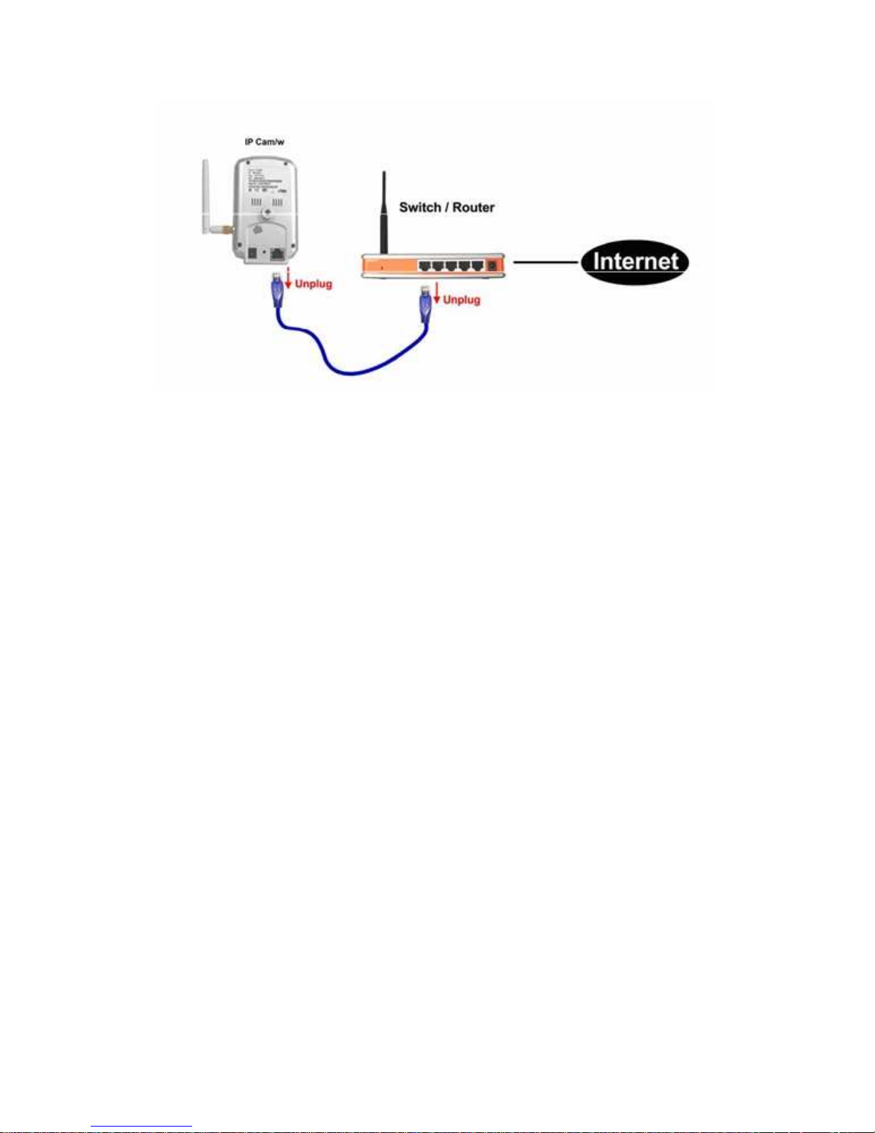
Third, unplug the Ethernet cable
If the WiFi test is successful, you can then enable the WiFi connection by
unplugging the Ethernet cable from the IP CAM. The IP CAM will detect the Ethernet
cable unplugged condition and start the WiFi connection. After the WiFi is connected,
the IP CAM will connect to the Internet immediately.
Notice :
1. Please remember that the WiFi connection will use a different IP address, you will
need to do the “Auto Search” function in the CamView again to find the IP CAM
again after the WiFi is connected.
2. If you want to switch back to the wired Ethernet connection, just plug in the
Ethernet cable into the IP CAM again. Do not need to disable the WiFi function on
the web pages.
12
Fixed Wireless/Wired IP Camera
Figure 2-9: Unplug the Ethernet cable to enable the WiFi function
13
 Loading...