

Page 1
Techniques for Replacing Surface Mount (SMD) IC’s
Every technician has had to replace a surface mount device (SMD) IC at one time or
another. How do you successfully remove and replace a surface mount IC? By successful
I mean removing the defective IC without damaging the delicate traces on the PC board
and aligning and soldering the replacement IC in place. Here are a few techniques you
can use to remove and replace a surface mount IC.
IC Removal
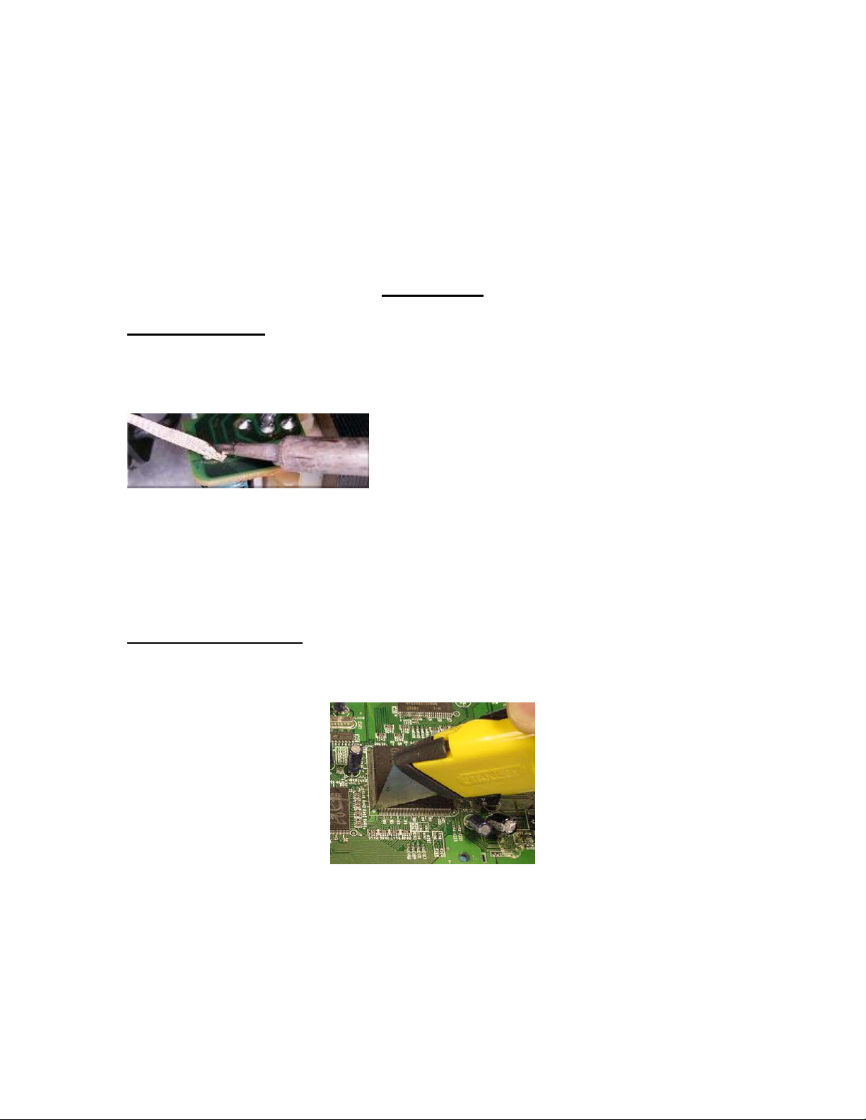
Desoldering Braid: Desoldering braid is a specially treated fine copper braid which
draws molten solder up into the braid where it solidifies. Desoldering braid is usually
sold on a small dispenser reel. The best way to use desoldering braid is to press the tip of
a hot iron onto a short length of braid that is placed over the joint to be de-soldered.
The iron will subsequently melt the solder, which will be drawn up into the braid. If the
desoldering braid is not drawing the solder but just seems to push it around the board add
a small amount of solder flux to the braid and try it again. After most of the solder has
been wicked use a dental pick or similar object and lift the IC pins while heating them
with a hot soldering iron.
Razor Knife Technique: Using a sharp razor knife, align the blade close to the body of
the IC and on the top of the row of pins. Applying a constant downward force cut the
pins away from the body of the IC. You will hear a distinct clicking sound as you severe
the pins.
Work your way down the row. Repeat this process for each row of pins until the body of
the IC is free from any pins and can be lifted away from the board. By cutting and
removing the body of the IC you are removing the “heat sink” that draws the heat from
the IC pins when you try to remove the IC with desoldering braid alone. Next, use
desoldering braid and a hot soldering iron to remove the remaining IC pins from the
board. This method allows you to remove the IC quickly and without damaging the PC
Page 2
board’s copper traces. One word of caution, this technique takes some practice. You are
using a sharp razor knife that WILL cut the boards traces if you use too much force while
cutting through the IC’s pins. Check the board before you solder the new IC in place. It
is highly recommended that you practice this method on some scrap boards before trying
it on a customers unit.
Wire removal method: Apply flux to the IC pins. Use desolder braid to remove as
much solder as possible from each pin. Thread fine stainless steel or enamel coated wire
under one row of pins. Secure one end of the wire on a nearby component (i.e. a large
Electrolytic capacitor). Starting at the loose end, heat each pin and pull wire
simultaneously. Pull the wire as close to the PCB as practical.
As the solder between the pin and pad melts, the wire will pop out and leave the pin
standing free of the pad. Repeat these steps for the other sides
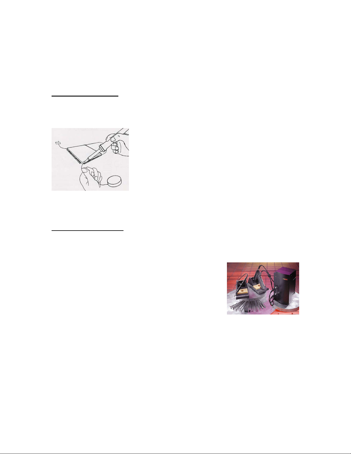
Hot air desoldering tool: There are several types of hot air desoldering systems.
Desoldering tools range from the inexpensive portable “pyropen” type that uses butane
fuel and a catalytic burner to produce heat, to the sophisticated temperature controlled,
auto-timed, variable suction, multi-nozzle hot air systems that can cost you hundreds or
thousands of dollars.
.
If you are on a tight budget, a handy device to get the job done is the “pyropen” or hot air
torch. These hot air, butane fueled, catalytic burner devices can be purchased for under
$100.00. To use this type of hot air device you have to ignite the torch, and adjust the
temperature. After it warms up place the nozzle tip about ¾ to 1 inch above the legs of
the IC you wish to remove. Move the nozzle tip around the IC to uniformly heat the IC’s
legs until the solder liquefies. Once the solder has liquefied use a dental pick or similar
device to lift the IC away from the board. As with other methods described here, practice
removing IC’s from a scrap board to hone your technique before you work on a
customers unit.
Page 3

IC Replacement
Soldering Techniques: OK, now that you removed the IC from the board, how do you
solder the replacement IC on the board? Here are some basic techniques for soldering a
replacement IC to the PC board. First, make sure the lands are CLEAN. That means
removing all solder and flux left behind during the IC extraction process. Next, check the
board to make sure the traces are not broken, cut or lifted. Place the new IC on the board
and position it so all of the pins are properly aligned (IC pin 1 to board land #1, etc.) on
the board. Once you have verified the traces are properly aligned, secure the new IC to
the board. One method to secure the IC is to use a piece of clear adhesive tape to hold the
IC to the board. Another method would be to apply pressure to the top of the IC using a
probe or tweezer to keep it in place while soldering it.
Secure the IC and solder.
Once the IC is secured, solder the corners of the IC first to hold the chip in place. If you
are using tape to secure the IC you can remove it once you have the corners soldered in
place. Add a bit of solder flux (liquid or paste) to the unsoldered pins and then solder the
remaining pins. Adding the flux allows the molten solder to adhere to the lands and IC
pins which will reduce the number of unreliable solder connections.
A good solder connection.
Next, check your work! Remove solder bridges between the IC’s pins with desoldering
braid and reflow any doubtful solder connections. You may want to use a magnifying
glass to help check your work.
Here are 10 basic steps to successfully soldering an IC (or any component):
1. Make sure all parts are clean and free from dirt and grease.
2. Secure the IC or component firmly to the board.
3. "Tin" the iron tip with a small amount of solder.
4. Clean the tip of the hot soldering iron on a damp sponge.
5. You can add a tiny amount of fresh solder to the clean tip.
6. Heat all parts of the joint with the iron for a second or so.
7. Continue heating and apply sufficient rosin core solder to form a smooth joint.
8. It only takes two or three seconds at most, to solder the average p c board joint.
9. Do not move parts until the solder has cooled.
10. Check you work for solder bridges and cold solder connections.
 Loading...