

Onkyo TX-SV353 Instruction Manual
Contents
Before using
Important safeguards........................ 2
Precautions ....................................... 3
Features............................................. 4
Supplied accessories......................... 4
Before operating this unit................. 5
Preparation
Connecting audio equipment............ 6
Connecting video equipment............ 7
Connecting speakers......................... 8
Positioning speakers......................... 9
Connecting the power....................... 9
Connecting antennas....................... 10
Operation
Listening to your favorite source.... 12
Tuning in a radio station................. 14
Using preset radio stations.............. 15
Selecting a Surround mode............. 16
Recording a source......................... 19
Using TAPE (MONITOR) Button ... 20
Programming remote controller
codes............................................ 21
A few important notes
Troubleshooting guide.................... 24
Specifications ................................. 25
Control positions and names .......... 26
Remote controller RC-383M.......... 27
BALANCETREBLEBASS
SYSTEM
ON
OFF
SPEAKERS A
SPEAKERS B
PHONES
DOLBY SURROUND
PRO • LOGIC
AMFMTAPE(MONITOR)TV/AUX PHONO
/1VIDEO VDP
/2
VIDEO VCR
MAXMIN
AUDIO VIDEO CONTROL RECEIVER TX-SV353
LR
C D
MASTER VOLUME
STAND-BY
123
456
789
GROUP 0/10 SCAN
MEMORY
FM MUTE / MODE
CLEAR
CENTER
MODE
SURROUND
MODE
DELAY TIME
TUNING DIRECT TUNINGDOWN UP
Audio Video Control Receiver
TX-SV353
Instruction Manual
Thank you for purchasing the Onkyo Audio Video
Control Receiver.
Please read this manual thoroughly before making
connections and turning on the power.
Following the instructions in this manual will enable
you to obtain optimum performance and listening
enjoyment from your new Audio Video Control
Receiver.
Please retain this manual for future reference.

2
Important safeguards
1.
Read Instructions
– All the safety and operating instructions
should be read before the appliance is operated.
2.
Retain Instructions
– The safety and operating instructions should
be retained for future reference.
3.
Heed Warnings
– All warnings on the appliance and in the operat-
ing instructions should be adhered to.
4.
Follow Instructions
– All operating and use instructions should be
followed.
5.
Water and Moisture
– The appliance should not be used near
water – for example, near a bathtub, washbowl, kitchen sink, laundry
tub, in a wet basement, or near a swimming pool, and the like.
6.
Carts and Stands
– The appliance should be used only with a cart
or stand that is recommended by the manufacturer.
7.
Wall or Ceiling Mounting
– The appliance should be mounted to
a wall or ceiling only as recommended by the manufacturer.
8.
Ventilation
– The appliance should be situated so that its location or
position does not interfere with its proper ventilation. For example, the
appliance should not be situated on a bed, sofa, rug, or similar surface
that may block the ventilation openings; or if placed in a built-in
installation, such as a book case or cabinet that may impede the flow
of air through the ventilation openings, there should be free space of at
least 20 cm and open up behind the appliance.
9.
Heat
– The appliance should be situated away from heat sources such
as radiators, heat registers, stoves, or other appliances (including
amplifiers) that produce heat.
10.
Power Sources
– The appliance should be connected to a power
supply only of the type described in the operating instructions or as
marked on the appliance.
11.
Polarization
– If the appliance is provided with a polarized plug
having one blade wider than the other, please read the following information: The polarization of the plug is a safety feature. The polarized
plug will only fit the outlet one way. If the plug does not fit fully into
the outlet, try reversing it. If there is still trouble inserting it, the user
should seek the services of a qualified electrician. Under no circumstances should the user attempt to defeat the polarization of the plug.
12.
Power-Cord Protection
– Power-supply cords should be routed so
that they are not likely to be walked on or pinched by items placed
upon or against them, especially near plugs, convenience receptacles,
and the point where they exit from the appliance.
6
A. An appliance and cart combination
should be moved with care. Quick
stops, excessive force, and uneven
surfaces may cause the appliance
and cart combination to overturn.
PORTABLE CART WARNING
S3125A
13.
Cleaning
– The appliance should be cleaned only as recommended
by the manufacturer.
14.
Power Lines
– An outdoor antenna should be located away from
power lines.
15.
Nonuse Periods
– The power cord of the appliance should be
unplugged from the outlet when left unused for a long period of time.
16.
Object and Liquid Entry
– Care should be taken so that objects
do not fall and liquids are not spilled into the enclosure through openings.
17.
Damage Requiring Service
– The appliance should be serviced
by qualified service personnel when:
A. The power-supply cord or the plug has been damaged; or
B. Objects have fallen, or liquid has been spilled into the appliance;
or
C. The appliance has been exposed to rain; or
D. The appliance does not appear to operate normally or exhibits a
marked change in performance; or
E. The appliance has been dropped, or the enclosure damaged.
18.
Servicing
– The user should not attempt to service the appliance
beyond that described in the operating instructions. All other servicing
should be referred to qualified service personnel.
19.
Outdoor Antenna Grounding
– If an outside antenna is connected to the receiver, be sure the antenna system is grounded so as to
provide some protection against voltage surges and built up static
charges. Article 810 of the National Electrical Code, ANSI/NFPA 70,
provides information with regard to proper grounding of the mast and
supporting structure, grounding of the lead-in wire to an antenna discharge unit, size of grounding conductors, location of the antenna-discharge unit, connection to grounding electrodes, and requirements for
the grounding electrode. See Figure 73.1.
FIGURE 73.1:
EXAMPLE OF ANTENNA GROUNDING AS PER
NATIONAL ELECTRICAL CODE
GROUND
CLAMP
ELECTRIC
SERVICE
EQUIPMENT
POWER SERVICE GROUNDING
ELECTRODE SYSTEM
(NEC ART 250, PART H)
GROUND CLAMPS
GROUNDING CONDUCTORS
(NEC SECTION 810-21)
ANTENNA
DISCHARGE UNIT
(NEC SECTION 810-20)
ANTENNA
LEAD IN
WIRE
NEC – NATIONAL ELECTRICAL CODE
S2898A
“WARNING”
“TO REDUCE THE RISK OF FIRE OR ELECTRIC SHOCK,
DO NOT EXPOSE THIS APPLIANCE TO RAIN OR MOISTURE.”
CAUTION:
“TO REDUCE THE RISK OF ELECTRIC SHOCK, DO NOT
REMOVE COVER (OR BACK). NO USER-SERVICEABLE
PARTS INSIDE. REFER SERVICING TO QUALIFIED SERVICE PERSONNEL.”
●
The lightning flash with arrowhead symbol, within
an equilateral triangle, is intended to alert the user
to the presence of uninsulated “dangerous voltage”
within the product’s enclosure that may be of sufficient magnitude to constitute a risk of electric shock
to persons.
●
The exclamation point within an equilateral triangle
is intended to alert the user to the presence of
important operating and maintenance (servicing)
instructions in the literature accompanying the
product.
WARNING
RISK OF ELECTRIC SHOCK
DO NOT OPEN
RISQUE DE CHOC ELECTRIQUE
NE PAS
OUVRIR
AVIS
3
Precautions
1. Warranty Claim
You can find the serial number on the rear panel. In case of warranty claim, please report this number.
2. Recording Copyright
Recording of copyrighted material for other than personal use is
illegal without permission of the copyright holder.
3. AC Fuse
The fuse is located inside the chassis and is not user-serviceable.
If power does not come on, contact your Onkyo authorized service
station.
4. Care
From time to time you should wipe the front and rear panels and
the cabinet with a soft cloth. For heavier dirt, dampen a soft cloth
in a weak solution of mild detergent and water, wring it out dry,
and wipe off the dirt. Following this, dry immediately with a clean
cloth. Do not use rough material, thinners, alcohol or other chemical solvents or cloths since these could damage the finish or
remove the panel lettering.
5. Power
WARNING
BEFORE PLUGGING IN THE UNIT FOR THE FIRST TIME,
READ THE FOLLOWING SECTION CAREFULLY.
●
The voltage of the available power supply differs according to
country or region. Be sure that the power supply voltage of the
area where this unit will be used meets the required voltage
(e.g., AC230V 50Hz or AC120V 60Hz) written on the rear
panel.
Models Equipped with a Voltage Selector
●
Worldwide models are equipped with a voltage selector to conform to local power supplies. Be sure to set this switch to
match the voltage of the power supply in your area before
plugging in the unit.
Memory Preservation
This unit does not require memory preservation batteries. A
built-in memory power back-up system preserves the contents
of the memory during power failures and even when the unit is
unplugged. The unit must be plugged in order to charge the
back-up system.
The memory preservation period after the unit has been
unplugged varies depending on climate and placement of the
unit. On the average, memory contents are protected over a
period of a few weeks after the last time the unit has been
unplugged. This period is shorter when the unit is exposed to a
highly humid climate.
For U.S. model
Note to CATV system installer:
●
This reminder is provided to call the CATV system installer’s
attention to Section 820-40 of the NEC which provides guidelines for proper grounding and, in particular, specifies that the
cable ground shall be connected to the grounding system of the
building, as close to the point of cable entry as practical.
For Canadian model
Modele pour les Canadien
●
For models having a power cord with a polarized plug.
CAUTION:
TO PREVENT ELECTRIC SHOCK, MATCH
WIDE BLADE OF PLUG TO WIDE SLOT, FULLY INSERT.
●
Sur les modèles dont la fiche est polarisée.
ATTENTION:
POUR ÉVITER LES CHOCS ÉLECTRIQUES, INTRODUIRE LA LAME LA PLUS LARGE DE LA
FICHE DANS LA BORNE CORRESPONDANTE DE LA
PRISE ET POUSSER JUSQU’AU FOND.
For Europen model
For British model
Replacement and mounting of an AC plug on the power supply cord
of this unit should be performed only by qualified service personnel.
IMPORTANT:
The wires in the mains lead are coloured in accordance with the
following code:
Blue: Neutral
Brown: Live
As the colours of the wires in the mains lead of this appliance may
not correspond with the coloured markings identifying the terminals in your plug, proceed as follows:
The wire which is coloured BLUE must be connected to the terminal
in the plug which is marked with the letter N or coloured BLACK.
The wire which is coloured BROWN must be connected to the terminal in the plug which is marked with the letter L or coloured RED.
IMPORTANT
A 5 amp fuse is fitted in this plug. Should the fuse need to be
replaced please ensure that the replacement fuse has a rating of 5
amps and that it is approved by ASTA or BSI to BS 1362. Check
for the ASTA mark or the BSI mark on the body of the fuse.
IF THE FITTED MOULDED PLUG IS UNSUITABLE FOR
THE SOCKET OUTLET IN YOUR HOME THEN THE FUSE
SHOULD BE REMOVED AND THE PLUG CUT OFF AND
DISPOSED OF SAFELY. THERE IS A DANGER OF SEVERE
ELECTRICAL SHOCK IF THE CUT OFF PLUG IS INSERTED
INTO ANY 13 AMP SOCKET.
If in any doubt please consult a qualified electrician.
Declaration of Conformity
We,
ONKYO EUROPE
ELECTRONICS GmbH
INDUSTRIESTRASSE 20
82110 GERMERING,
GERMANY
declare in own responsibility, that the ONKYO product described
in this instruction manual is in compliance with the corresponding
technical standards such as EN55013, EN55020, EN61000-3-2, -3-3
and EN60065
GERMERING, GERMANY
ONKYO EUROPE ELECTRONICS GmbH
K.OTSU
4
Features
Power output:
European models:
Stereo mode
2 × 60 watts at 6 ohms (DIN)
Surround mode
Front L/R and Center Channels
3 × 50 watts at 6 ohms (DIN)
Rear Channels (Rear channel only driven)
15 watts + 15 watts at 6 ohms (DIN)
Asian models:
Stereo mode
2 × 80 watts at 6 ohms, 1 kHz (EIAJ)
Surround mode
Front L/R and Center Channels
3 × 65 watts at 6 ohms, 1 kHz (EIAJ)
Rear Channels (Rear channel only driven)
20 watts + 20 watts at 6 ohms, 1 kHz (EIAJ)
●
Dolby* Pro Logic and Hall Surround mode for spacious
sound
●
All channels boast discrete output stage circuits (extremely
rare in this receiver class) for accurate high-current, lowimpedance drive
●
Costly, high-quality parts such as large power transistors,
oversized transformer and a heavy-duty, one-piece, extruded
heat sink enhance low-impedance drive capability
●
Dedicated line-level subwoofer output
●
4 Audio and 2 AV inputs accommodate a complete AV system
●
A/B Speaker selector and outputs
●
Tape monitor
●
Adjustable digital delay
●
30 FM/AM random presets
●
Preset scan tuning
●
3 Station group presets (10 stations per group)
●
RDS with PS (European models only)
●
Direct access tuning
●
Motor-driven, precision 4-gang volume control
●
Headphone jack
●
Audio mute, sleep timer (via remote)
●
Battery-free memory backup
●
Compatible remote controller
*Manufactured under license from Dolby Laboratories.
“Dolby”, “Pro Logic” and the double-D symbol are trademarks of
Dolby Laboratories. Confidential Unpublished Works. ©1992-1997 Dolby
Laboratories, Inc. All rights reserved.
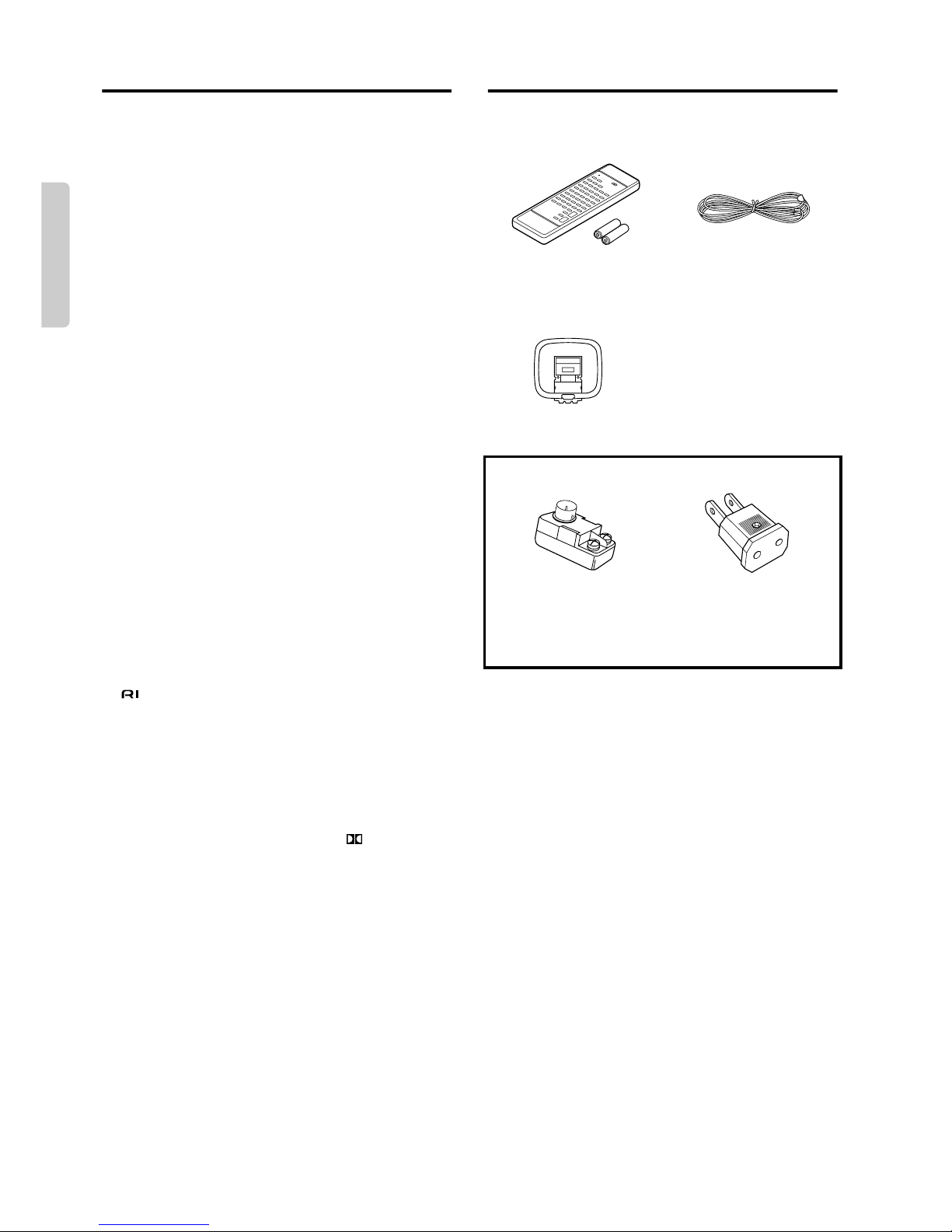
Supplied accessories
Check that the following accessories are supplied with this unit.
The number of each supplied accessory is indicated in parentheses.
Remote controller (RC-383M) (1) T-shaped FM antenna (1)
Batteries (size AA, R6, or UM-3) (2)
AM loop antenna (1)
(worldwide and some other models) (some worldwide models only)
75/300 ohm antenna CV plug (Shape may vary
adaptor (1) according to the area where
purchased.) (1)
5
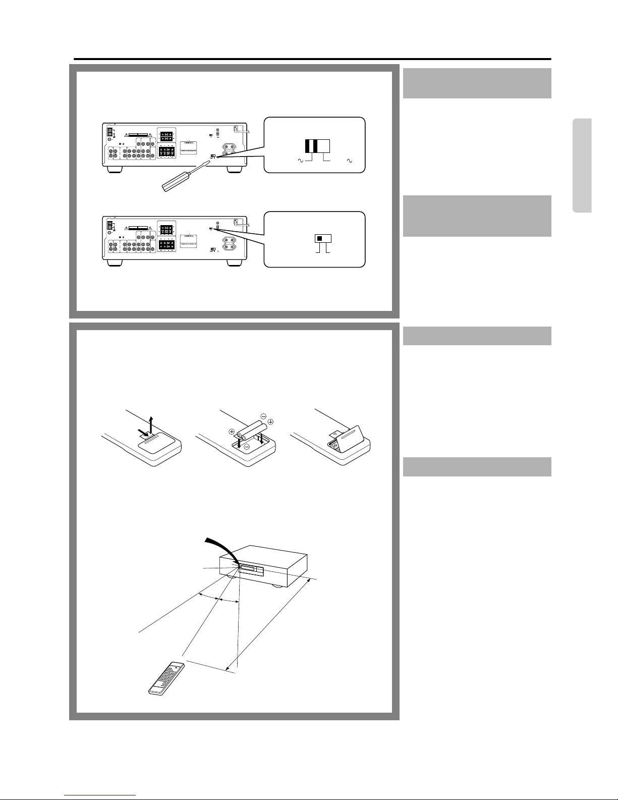
Before operating this unit
1.
Determine the proper voltage for your
area: 220-230 V or 120 V.
2. If the setting on the voltage selector is
not correct, insert a screwdriver into the
groove in the switch and slide the
switch completely to the right (120 V)
or the left (220-230 V), whichever is
appropriate.
The worldwide model is equipped with a
switch that controls the AM (9 kHz/
10 kHz) band tuning steps.
Please set this switch to match the tuning
step frequency in your area.
U.S. & Canada: 10 kHz
Other areas: 9 kHz
The following information will help you
get optimal use from the remote controller.
●
Place this unit away from direct bright
light which can prevent proper operation of the remote controller.
●
Make sure audio rack doors do not have
tinted glass. Placing this unit behind
such a door may prevent proper remote
controller operation.
Remove the battery compartment cover by
opening it as shown in the illustration.
Load two AA (R6 or UM-3)-size batteries
into the remote controller with the plus (+)
and minus (–) terminals positioned as indicated by the diagram inside the battery
compartment, then close the cover.
●
Remove empty batteries immediately to
avoid corrosion damage.
●
To avoid potential corrosion damage,
never mix old batteries with new ones.
●
The manganese batteries supplied with
this unit have a service life of approximately six months, depending on the
frequency of use.
●
The TX-SV353 comes equipped with
two AA (R6 or UM-3) manganese batteries, but we recommend that long-life
AA (LR6 or AM-3) size alkaline batteries be used when replacing the batteries.
Setting the voltage selector
(worldwide model only)
Setting the AM tuning step
frequency
(worldwide model only)
Using the remote controller
Loading the batteries
PHONO
CD TV/AUX TAPE
GND
RLR
L
ANTENNA
FM
75Ω
AM
(PLAY)
INPUT
(REC)
OUTPUT
VIDEO-1
VIDEO-1
INPUT
INPUT
VIDEO-2
VIDEO-2
INPUT
INPUT
OUTPUT
OUTPUT
MONITOR
OUTPUT
V V
SUBWOOFER
PRE OUT
WARNING
RISK OF ELECTRIC SHOCK
DO NOT OPEN
AVIS
RISQUE DE CHOC ELECTRIQUE
NE PAS OUVRIR
FRONT SPEAKERS
L
L
R
R
REAR SPEAKERS CENTER
SPEAKERL
R
ABA
B
RATING:
AUDIO VIDEO CONTROL
RECEIVER
MODEL NO. TX-SV353
120V220-230V
VOLTAGE SELECTOR
REMOTE
CONTROL
AC OUTLETS
SWITCHED
TOTAL 100W MAX.
10kHz
9kHz
AM FREQ. STEP
MANUFACTURED UNDER LICENSE FROM DOLBY
LABORATORIES LICENSING CORPORATION.
“DOLBY”, THE COUBLE-D SYMBOL AND “PRO LOGIC”
ARE TRADEMARKS OF DOLBY LABORATORIES
LICENSING CORPORATION.
CAUTION: SPEAKER IMPEDANCE
FRONT A OR B: 6OHMS MIN. / SPEAKER
FRONT A+B:12OHMS MIN. / SPEAKER
CENTER / REAR:6 OHMS MIN. / SPEAKER
120V220-230V
VOLTAGE SELECTOR
10kHz
9kHz
AM FREQ. STEP
30˚
30˚
Insert the batteries into the remote controller according to the illustration.
1 2
3
TX-SV353
Remote controller sensor
STAND-BY indicator
approx. 5 m
(16 feet)
6
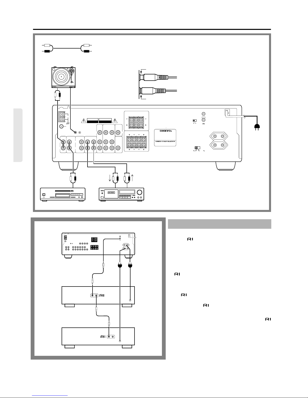
Connecting audio equipment
PHONO
CD TV/AUX TAPE
GND
R
L
R
L
ANTENNA
FM
75Ω
AM
(PLAY)
INPUT
(REC)
OUTPUT
VIDEO-1
VIDEO-1
INPUT
INPUT
VIDEO-2
VIDEO-2
INPUT
INPUT
OUTPUT
OUTPUT
MONITOR
OUTPUT
V V
SUBWOOFER
PRE OUT
WARNING
RISK OF ELECTRIC SHOCK
DO NOT OPEN
AVIS
RISQUE DE CHOC ELECTRIQUE
NE PAS OUVRIR
FRONT SPEAKERS
L
L
R
R
REAR SPEAKERS CENTER
SPEAKERL
R
A
B
A
B
RATING:
AUDIO VIDEO CONTROL
RECEIVER
MODEL NO. TX-SV353
120V220-230V
VOLTAGE SELECTOR
REMOTE
CONTROL
AC OUTLETS
SWITCHED
TOTAL 100W MAX.
10kHz
9kHz
AM FREQ. STEP
MANUFACTURED UNDER LICENSE FROM DOLBY
LABORATORIES LICENSING CORPORATION.
“DOLBY”, THE COUBLE-D SYMBOL AND “PRO LOGIC”
ARE TRADEMARKS OF DOLBY LABORATORIES
LICENSING CORPORATION.
CAUTION: SPEAKER IMPEDANCE
FRONT A OR B: 6OHMS MIN. / SPEAKER
FRONT A+B:12 OHMS MIN. / SPEAKER
CENTER / REAR: 6 OHMS MIN. / SPEAKER
OUTPUT
RL
RL
RL
LINE IN
LINE OUT
PHONO
OUT
● Refer to the instruction manual of each component when making connections.
● On each pair of connectors, the lower connector (red and marked R) corresponds to
the right channel and the upper connector (white and marked L) to the left channel.
● Insert the plugs and connectors securely. Remember that improper connection can
result noise, poor performance, or damage to the equipment.
To wall outlet
CAUTION:
Do not plug in the power
cord until all connections have been made.
Turntable
CD player Tape deck
L (Left)
R (Right)
L
R
Improper connection
Insert completely
Cassette tape decks and compact disc players equipped with
an Onkyo connector can be operated using the remote
controller included with this unit.
To enable remote controller operation of other components,
connect the remote controller cable as shown at the left.
NOTE:
●
To enable proper remote controller operation, both the
cables and the audio cables must be connected to the
units.
●
This unit’s remote controller cannot be used to control
Onkyo turntables.
●
An remote controller cable equipped with 1/8” (3.5
mm) mini jacks is included with any other component
installed with an connector.
The direct function feature
When a compact disc player and a tape deck with the
connector are connected together, you can use the direct
function feature.
When you operate the desired component (compact disc
player or tape deck), The TX-SV353 Input Selector automatically switches to that component.
In this way, it is not necessary to operate the Input Selector
to change listening sources.
Remote controller connections
REMOTE
CONTROL
AC OUTLETS
SWITCHED
TOTAL 100W MAX.
TX-SV353
7
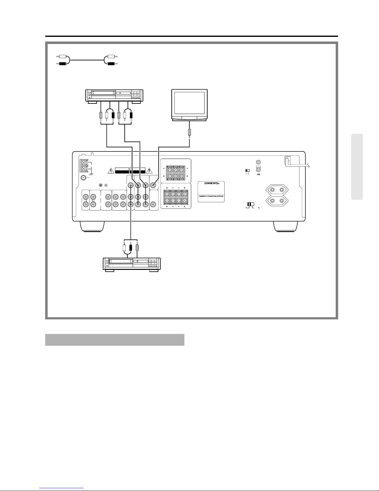
Connecting video equipment
Refer to the instruction manual for each component when making connections.
On each pair of connectors, the lower connector (red and marked R) corresponds to the
right channel and the upper connector (white and marked L) to the left channel.
Video cassette recorder
(Video-1)
Video cassette recorder
(Video-2)
TV/monitor
If there is interference between the TV and the TX-SV353,
place the unit as far from the TV as possible. We do not
recommend the use of a common TV/FM antenna. (Refer
to
Connecting antennas
on page 10, 11.)
PHONO
CD TV/AUX TAPE
GND
R
L
R
L
ANTENNA
FM
75Ω
AM
(PLAY)
INPUT
(REC)
OUTPUT
VIDEO-1
VIDEO-1
INPUT
INPUT
VIDEO-2
VIDEO-2
INPUT
INPUT
OUTPUT
OUTPUT
MONITOR
OUTPUT
V V
SUBWOOFER
PRE OUT
WARNING
RISK OF ELECTRIC SHOCK
DO NOT OPEN
AVIS
RISQUE DE CHOC ELECTRIQUE
NE PAS OUVRIR
FRONT SPEAKERS
L
L
R
R
REAR SPEAKERS CENTER
SPEAKERL
R
A
B
A
B
RATING:
AUDIO VIDEO CONTROL
RECEIVER
MODEL NO. TX-SV353
120V220-230V
VOLTAGE SELECTOR
REMOTE
CONTROL
AC OUTLETS
SWITCHED
TOTAL 100W MAX.
10kHz
9kHz
AM FREQ. STEP
MANUFACTURED UNDER LICENSE FROM DOLBY
LABORATORIES LICENSING CORPORATION.
“DOLBY”, THE COUBLE-D SYMBOL AND “PRO LOGIC”
ARE TRADEMARKS OF DOLBY LABORATORIES
LICENSING CORPORATION.
CAUTION: SPEAKER IMPEDANCE
FRONT A OR B: 6 OHMS MIN. / SPEAKER
FRONT A+B:12 OHMS MIN. / SPEAKER
CENTER / REAR: 6 OHMS MIN. / SPEAKER
VIDEO OUT
AUDIO OUT
VIDEO IN
VIDEO IN
AUDIO IN
VIDEO OUT
AUDIO OUT
L (Left)
R (Right)
L
R
The power to components connected to the SWITCHED outlets is
turned on and off via the POWER button on the remote controller.
(Note: The remote controller cannot be used when the SYSTEM
switch on the front panel is set to OFF.)
NOTE:
●
The shape, number and total capacity of the AC outlets may
differ according to the model and the area in which the unit
was purchased. Be careful that other components connected to
this unit do not exceed the capacity that is printed on the rear
panel above the AC outlets.
AC outlet connections
8
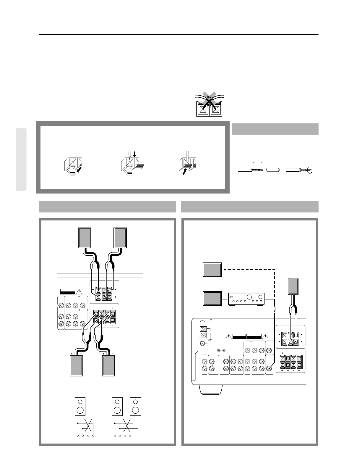
Connecting speakers
●
Please connect each speaker according to the illustration, observing the correct connections for R, L, + and –.
●
Do not use unnecessarily long or extremely thin speaker cables. If the DC resistance of the speaker cables is too high, the damping
factor will decrease, adversely affecting the sound quality.
Speaker Impedance
This unit is designed to produce optimum sound quality when speakers with impedances within the set ranges are connected. Please check
the following information and choose speakers with the necessary impedances for the connections.
FRONT SPEAKERS:
A or B: 6 ohms min./speaker
A + B : 12 ohms min./speaker
CENTER SPEAKER:
6 ohms min.
REAR (SURROUND) SPEAKERS:
6 ohms min./speaker
1. Open the lever.
2. Twist wire ends very tight, and insert the
wire.
3. Close the lever.
Before making any connections, please refer
to the explanation of “Speaker impedance.”
Connecting speaker cables
1
23
15 mm
Front and Rear speakers
VIDEO-1
VIDEO-1
INPUT
INPUT
VIDEO-2
VIDEO-2
INPUT
INPUT
OUTPUT
OUTPUT
MONITOR
OUTPUT
V V
SUBWOOFER
PRE OUT
AVIS
RISQUE DE CHOC ELECTRIQUE
NE PAS OUVRIR
FRONT SPEAKERS
L
L
R
R
REAR SPEAKERS CENTER
SPEAKERL
R
A
B
A
B
● When using only one speaker or when you wish to listen to
monaural (mono), the single speaker should never be connected in
parallel to both the right and left channel terminals at once.
B terminals
Use these terminals to
connect a second pair
of front speakers.
+––+ +––+
RL RL
Rear (surround) Rear (surround)
Front Left Front Right
Left Speaker Right Speaker
SpeakerSpeaker
Center speaker and subwoofer
PHONO
CD TV/AUX TAPE
GND
R
L
R
L
ANTENNA
FM
75Ω
AM
(PLAY)
INPUT
(REC)
OUTPUT
VIDEO-1
VIDEO-1
INPUT
INPUT
VIDEO-2
VIDEO-2
INPUT
INPUT
OUTPUT
OUTPUT
MONITOR
OUTPUT
V V
SUBWOOFER
PRE OUT
WARNING
RISK OF ELECTRIC SHOCK
DO NOT OPEN
AVIS
RISQUE DE CHOC ELECTRIQUE
NE PAS OUVRIR
FRONT SPEAKERS
L
L
R
R
REAR SPEAKERS CENTER
SPEAKERL
R
A
B
A
B
The SUBWOOFER PRE OUT jack can be connected to a
subwoofer amplifier, or to a subwoofer with a built-in amplifier.
● When using any unit connected to the SUBWOOFER PRE
OUT jack, set the SPEAKERS A button on the front panel
to ON.
Active Subwoofer
Center Speaker
Amplifier
Subwoofer
Note:
To prevent damage to circuitry, never shortcircuit the positive (+) and negative (–)
speaker wires.
NO
9
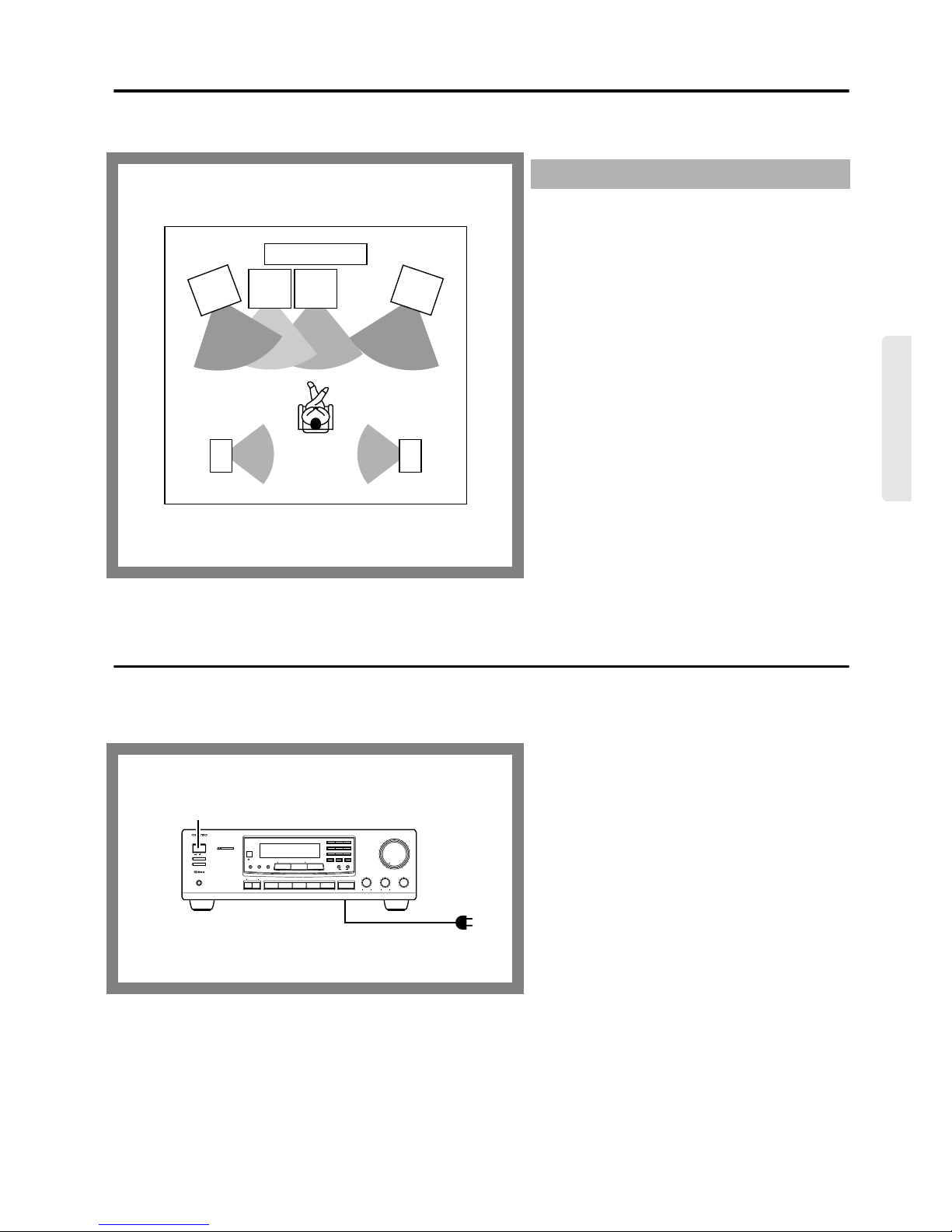
Positioning speakers
Speaker placement plays an important role in the reproduction of Surround sound. The manner in which the speakers are placed varies
depending on the size of the room and the wall coverings used in the room. The illustration below shows an example of a layout for standard
speaker placement. Refer to this example when positioning the speakers in order to experience the best of Surround sound.
For ideal Surround effects, all speakers should be installed.
If a center speaker or subwoofer is not connected, the sound
from the unused channel is properly distributed to the connected speakers in order to produce the best Surround sound
possible.
Front:
The left, right, and center speakers should face the seated listener and be placed at ear level. The center speaker produces
a richer sound image by enhancing the perception of the
sound’s source and movement.
Rear (surround):
Place the left and right Rear (surround) speakers 1 m (3 feet)
above the listener’s ear level and toward the sides of the
room, making sure that the listener is within the speakers’
dispersion angle. These speakers produce the feel of a moving sound while generating the sensation of being in the middle of the action.
Subwoofer:
Install a subwoofer with a built-in power amplifier for powerful bass sounds. The placement of the subwoofer does not
affect the final quality of the sound image too much, so you
can install it with the room layout in mind.
Refer to the speaker instruction manual for more details.
Standard speaker placement
TV or Screen
Center
speaker
Rear (surround)
speaker
Right
Rear (surround)
speaker
Left
Listener
Sub-
woofer
speaker
Front
speaker
Left
Front
speaker
Right
Connecting the power
Before plugging in the unit, confirm that all connections have been made properly.
Before turning on the power, be sure that the MASTER VOLUME control knob is fully turned counterclockwise.
Turning on this unit’s power may cause a momentary power surge, which might interfere with other electrical equipment, such as computers. If so, use a wall outlet on a different circuit.
After plugging the TX-SV353’s power cord into an AC outlet, press the SYSTEM switch to put the unit in power-on status (the unit can be operated and its display is lit). The remote
controller cannot be used to operate the TX-SV353 if the
SYSTEM switch is not set to ON.
When the SYSTEM switch is set to ON, pressing the POWER
button on the remote controller switches the TX-SV353
between stand-by status (the STAND-BY indicator is lit) and
power-on status (the display is lit).
Pressing the SYSTEM switch on the TX-SV353 to set it to
OFF turns off the unit. (When the SYSTEM switch is set to
OFF, only a small amount of power is used.)
SYSTEM switch
BALANCETREBLEBASS
SYSTEM
ON
OFF
SPEAKERS A
SPEAKERS B
PHONES
DOLBY SURROUND
PRO • LOGIC
AMFMTAPE(MONITOR)TV/AUX PHONO
/1VIDEO VDP
/2
VIDEO VCR
MAXMIN
AUDIO VIDEO CONTROL RECEIVER TX-SV353
LR
C D
MASTER VOLUME
STAND-BY
123
456
789
GROUP 0/10 SCAN
MEMORY
FM MUTE / MODE
CLEAR
CENTER
MODE
SURROUND
MODE DELAY TIME
TUNING DIRECT TUNINGDOWN UP
 Loading...