

Page 1

7.1ch Home Theater System
HT-S780
AV Receiver (HT-R530)
Front Speaker (SKF-530F)
Center Speaker (SKC-530C)
Surround Speaker (SKM-530S)
Surround Back Speaker (SKB-530)
Powered Subwoofer (SKW-530)
Instruction Manual
Contents
Introduction ..................................... 2
Connection .................................... 18
Turning On & First Time Setup..... 32
Basic Operation
Playing your AV components....... 34
Using the Tuner............................ 36
Thank you for purchasing an Onkyo 7.1ch Home
Theater System. Please read this manual thoroughly
before making connections and plugging in the unit.
Following the instructions in this manual will enable
you to obtain optimum performance and listening
enjoyment from your new 7.1ch Home Theater System.
Please retain this manual for future reference.
Enjoying the Listening Modes ..... 40
Advanced Operation..................... 44
Troubleshooting ............................ 55
E
n
Page 2
WARNING:
TO REDUCE THE RISK OF FIRE OR ELECTRIC
SHOCK, DO NOT EXPOSE THIS APPARATUS
TO RAIN OR MOISTURE.
CAUTION:
TO REDUCE THE RISK OF ELECTRIC SHOCK,
DO NOT REMOVE COVER (OR BACK). NO
USER-SERVICEABLE PARTS INSIDE. REFER
SERVICING TO QUALIFIED SERVICE
PERSONNEL.
Important Safety Instructions
WARNING
RISK OF ELECTRIC SHOCK
DO NOT OPEN
The lightning flash with arrowhead symbol, within an
equilateral triangle, is intended to alert the user to the
presence of uninsulated “dangerous voltage” within
the product’s enclosure that may be of sufficient
magnitude to constitute a risk of electric shock to
persons.
The exclamation point within an equilateral triangle is
intended to alert the user to the presence of important
operating and maintenance (servicing) instructions in
the literature accompanying the appliance.
AVIS
RISQUE DE CHOC ELECTRIQUE
OUVRIR
NE PAS
1. Read these instructions.
2. Keep these instructions.
3. Heed all warnings.
4. Follow all instructions.
5. Do not use this apparatus near water.
6. Clean only with dry cloth.
7. Do not block any ventilation openings. Install in
accordance with the manufacturer’s instructions.
8. Do not install near any heat sources such as radiators, heat registers, stoves, or other apparatus
(including amplifiers) that produce heat.
9. Do not defeat the safety purpose of the polarized or
grounding-type plug. A polarized plug has two
blades with one wider than the other. A grounding
type plug has two blades and a third grounding
prong. The wide blade or the third prong are provided for your safety. If the provided plug does not
fit into your outlet, consult an electrician for
replacement of the obsolete outlet.
10. Protect the power cord from being walked on or
pinched particularly at plugs, convenience receptacles, and the point where they exit from the apparatus.
11. Only use attachments/accessories specified by the
manufacturer.
12.
Use only with the cart, stand,
PORTABLE CART WARNING
tripod, bracket, or table specified by the manufacturer, or
sold with the apparatus.
When a cart is used, use caution when moving the cart/
apparatus combination to
avoid injury from tip-over.
S3125A
13. Unplug this apparatus during lightning storms or
when unused for long periods of time.
14. Refer all servicing to qualified service personnel.
Servicing is required when the apparatus has been
damaged in any way, such as power-supply cord or
plug is damaged, liquid has been spilled or objects
have fallen into the apparatus, the apparatus has
been exposed to rain or moisture, does not operate
normally, or has been dropped.
15. Damage Requiring Service
Unplug the apparatus from the wall outlet and refer
servicing to qualified service personnel under the
following conditions:
A. When the power-supply cord or plug is damaged,
B. If liquid has been spilled, or objects have fallen
into the apparatus,
C. If the apparatus has been exposed to rain or
water,
D. If the apparatus does not operate normally by
following the operating instructions. Adjust only
those controls that are covered by the operating
instructions as an improper adjustment of other
controls may result in damage and will often
require extensive work by a qualified technician
to restore the apparatus to its normal operation,
E. If the apparatus has been dropped or damaged in
any way, and
F. When the apparatus exhibits a distinct change in
performance this indicates a need for service.
16. Object and Liquid Entry
Never push objects of any kind into the apparatus
through openings as they may touch dangerous voltage points or short-out parts that could result in a
fire or electric shock.
The apparatus shall not be exposed to dripping or
splashing and no objects filled with liquids, such as
vases shall be placed on the apparatus.
Don’t put candles or other burning objects on top of
this unit.
17. Batteries
Always consider the environmental issues and follow local regulations when disposing of batteries.
18. If you install the apparatus in a built-in installation,
such as a bookcase or rack, ensure that there is adequate ventilation.
Leave 20 cm (8") of free space at the top and sides
and 10 cm (4") at the rear. The rear edge of the shelf
or board above the apparatus shall be set 10 cm (4")
away from the rear panel or wall, creating a flue-like
gap for warm air to escape.
2
Page 3

Precautions
1. Recording Copyright—Unless it’s for personal use
only, recording copyrighted material is illegal without the permission of the copyright holder.
2. AC Fuse—The AC fuse inside the unit is not userserviceable. If you cannot turn on the unit, contact
your Onkyo dealer.
3. Care—Occasionally you should dust the unit all
over with a soft cloth. For stubborn stains, use a soft
cloth dampened with a weak solution of mild detergent and water. Dry the unit immediately afterwards
with a clean cloth. Don’t use abrasive cloths, thinners, alcohol, or other chemical solvents, because
they may damage the finish or remove the panel lettering.
4. Power
WARNING
BEFORE PLUGGING IN THE UNIT FOR THE
FIRST TIME, READ THE FOLLOWING SECTION CAREFULLY.
AC outlet voltages vary from country to country.
Make sure that the voltage in your area meets the
voltage requirements printed on the unit’s rear panel
(e.g., AC 230 V, 50 Hz or AC 120 V, 60 Hz).
Some models have a voltage selector switch for
compatibility with power systems around the world.
Before you plug in such a model, make sure that the
voltage selector is set to the correct voltage for your
area.
Setting the [STANDBY/ON] switch to STANDBY
does not fully shutdown the unit. If you do not
intend to use the unit for an extended period,
remove the power cord from the AC outlet.
5. Never Touch this Unit with Wet Hands—Never
handle this unit or its power cord while your hands
are wet or damp. If water or any other liquid gets
inside this unit, have it checked by your Onkyo
dealer.
6. Handling Notes
• If you need to transport this unit, use the original
packaging to pack it how it was when you originally bought it.
• Do not leave rubber or plastic items on this unit
for a long time, because they may leave marks on
the case.
• This unit’s top and rear panels may get warm
after prolonged use. This is normal.
• If you do not use this unit for a long time, it may
not work properly the next time you turn it on, so
be sure to use it occasionally.
Memory Backup
The AV receiver uses a battery-less memory backup
system in order to retain radio presets and other settings
when it’s unplugged or in the case of a power failure.
Although no batteries are required, the AV receiver
must be plugged into an AC outlet in order to charge the
backup system. Once it has been charged, the AV
receiver will retain the settings for several weeks,
although this depends on the environment and will be
shorter in humid climates.
For U.S. models
FCC Information for User
CAUTION:
The user changes or modifications not expressly
approved by the party responsible for compliance could
void the user’s authority to operate the equipment.
NOTE:
This equipment has been tested and found to comply
with the limits for a Class B digital device, pursuant to
Part 15 of the FCC Rules. These limits are designed to
provide reasonable protection against harmful interference in a residential installation.
This equipment generates, uses and can radiate radio
frequency energy and, if not installed and used in accordance with the instructions, may cause harmful interference to radio communications. However, there is no
guarantee that interference will not occur in a particular
installation. If this equipment does cause harmful interference to radio or television reception, which can be
determined by turning the equipment off and on, the
user is encouraged to try to correct the interference by
one or more of the following measures:
• Reorient or relocate the receiving antenna.
• Increase the separation between the equipment and
receiver.
• Connect the equipment into an outlet on a circuit different from that to which the receiver is connected.
• Consult the dealer or an experienced radio/TV technician for help.
3
Page 4

Precautions—Continued
Speaker Precautions
For Canadian Models
NOTE: THIS CLASS B DIGITAL APPARATUS
COMPLIES WITH CANADIAN ICES-003.
For models having a power cord with a polarized plug:
CAUTION: TO PREVENT ELECTRIC SHOCK,
MATCH WIDE BLADE OF PLUG TO WIDE SLOT,
FULLY INSERT.
Modèle canadien
REMARQUE: CET APPAREIL NUMÉRIQUE DE
LA CLASSE B EST CONFORME À LA NORME
NMB-003 DU CANADA.
Sur les modèles dont la fiche est polarisée:
ATTENTION: POUR ÉVITER LES CHOCS ÉLEC-
TRIQUES, INTRODUIRE LA LAME LA PLUS
LARGE DE LA FICHE DANS LA BORNE CORRESPONDANTE DE LA PRISE ET POUSSER
JUSQU’AU FOND.
Placement
• The speaker cabinets are made out of wood and are
therefore sensitive to extreme temperatures and
humidity, do not put them in locations subject to direct
sunlight or in humid places, such as near an air conditioner, humidifier, bathroom, or kitchen.
• Do not put water or other liquids close to the speakers.
If liquid is spilled over the speakers, the drive units
may be damaged.
• Speakers should only be placed on sturdy, flat surfaces
that are free from vibration. Putting them on uneven or
unstable surfaces, where they may fall and cause damage, will affect the sound quality.
• Subwoofer is designed to be used in the upright vertical position only. Do not use it in the horizontal or
tilted position.
• If the unit is used near a turntable or CD player, howling or slipping of sound may occur. To prevent this,
move the unit away from the turntable or CD player
otherwise lower the unit’s output level.
Using Close to a TV or Computer
TVs and computer monitors are magnetically sensitive
devices and as such are likely to suffer discoloration or
picture distortion when conventional speakers are placed
nearby. To prevent this, the SKF-530F and SKC-530C
feature internal magnetic shielding. In some situations,
however, discoloration may still be an issue, in which case
you should turn off your TV or monitor, wait 15 to 30
minutes, and then turn it back on again. This normally
activates the degaussing function, which neutralizes the
magnetic field, thereby removing any discoloration
effects. If discoloration problems persist, try moving the
speakers away from your TV or monitor. Note that discoloration can also be caused by a magnet or demagnetizing
tool that’s too close to your TV or monitor.
4
Input Signal Warning
The speakers can handle the specified input power when
used for normal music reproduction. If any of the following signals are fed to them, even if the input power is
within the specified rating, excessive current may flow in
the speaker coils, causing burning or wire breakage:
1. Interstation noise from an untuned FM radio.
2. Sound from fast-forwarding a cassette tape.
3. High-pitched sounds generated by an oscillator, elec-
tronic musical instrument, and so on.
4. Amplifier oscillation.
5. Special test tones from audio test CDs and so on.
6. Thumps and clicks caused by connecting or discon-
necting audio cables (Always turn off your amplifier
before connecting or disconnecting cables.)
7. Microphone feedback.
Page 5
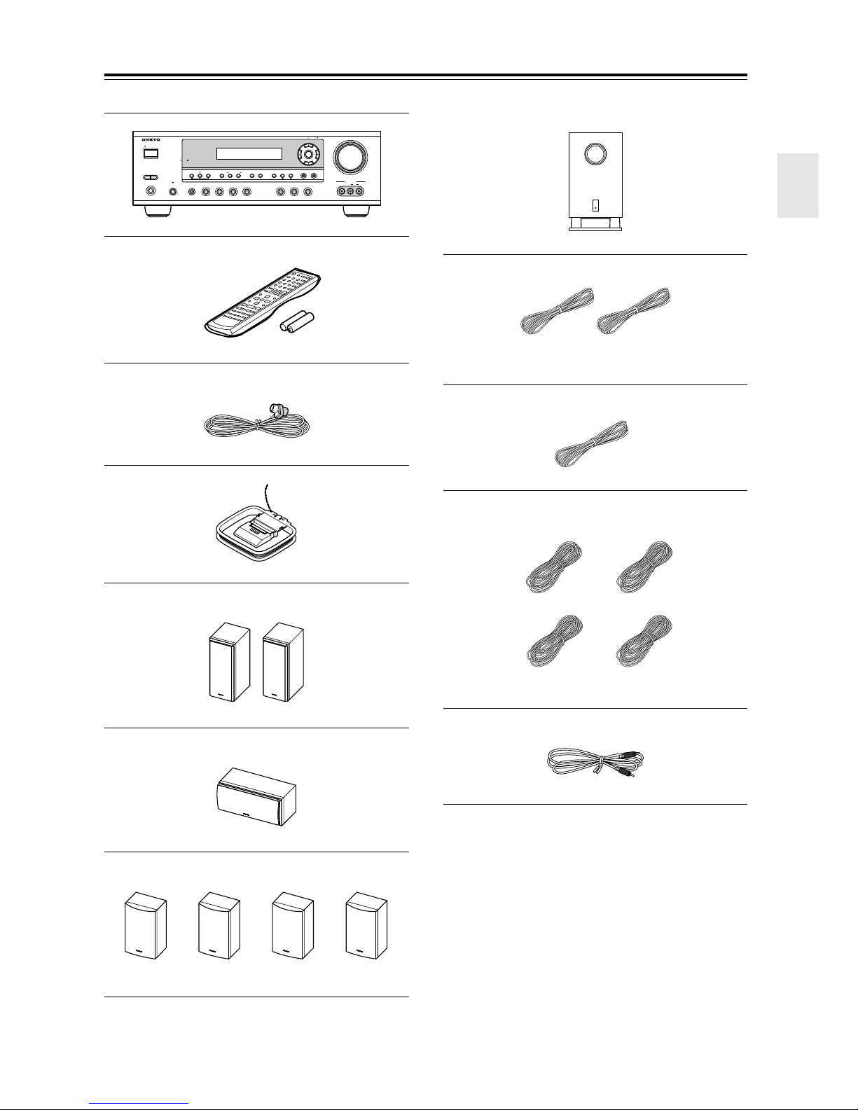
Supplied Accessories
Make sure you have the following accessories:
TUNING / PRESET
STANDBY/ON
A SPEAKERS B
STANDBY
+
TONE
LISTENING MODE
DISPLAY
DIGITAL INPUT
PHONES
PURE AUDIO
STEREO
MULTl CH DVD VIDEO 1 VIDEO 2
VCR
VIDEO 3 TAPE TUNER CD
RT/PTY/TP MEMORY
RETURN
TUNING MODE
CLEAR
AV receiver (HT-R530)
Remote controller & two batteries (AA/R6)
MASTER VOLUME
ENTER
SETUP
VIDEO 3 INPUT
VIDEO
AUDIO
LR
Subwoofer (SKW-530)
(Red) (White)
Speaker cable for front speakers 15 ft. (4.5 m)
Indoor FM antenna
AM loop antenna
Front speakers (SKF-530F)
Center speaker (SKC-530C)
(Green)
Speaker cable for center speaker 10 ft. (3 m)
(Blue) (Gray)
(Brown) (Tan)
Speaker cables for surround speakers 30 ft. (9 m)
RCA cable for subwoofer connection 10 ft. (3 m)
* In catalogs and on packaging, the letter at the end of the
product name indicates the color. Specifications and operation are the same regardless of color.
Surround and Surround back speakers
(SKM-530S/SKB-530)
5
Page 6

Features
Amp
• 7-channel amplifier
• 110 watts per channel at 8 Ω (FTC)
• WRAT (Wide Range Amplifier Technology)
• Optimum gain volume circuitry
• OptiResponse™ Equalizer (OR-EQ™)
*1
function
Processing
• Dolby*2 Digital EX and Dolby Pro Logic IIx
• DTS, DTS-ES Matrix/Discrete, DTS Neo:6, and DTS
96/24 processing
• Cinema Filter function
• Linear PCM 192 kHz/24-bit D/A converters on all
channels
• Pure Audio listening mode (not North American
model)
• Powerful and highly accurate 32-bit DSP Processing
*3
Audio/Video
• Adjustable crossover (60, 80, 100, 120, 150 Hz)
• HDTV-capable component video (3 inputs, 1 output)
• 3 S-Video inputs, 2 outputs
• 4 assignable digital inputs (3 optical, 1 coaxial)
• Subwoofer pre out
• Color-coded multichannel input for use with Super
Audio CD and DVD-Audio
• A/B speaker drive
• Color-coded speaker terminal posts
FM/AM Tuner
• 30 FM/AM presets
• FM/AM auto tuning
Remote Controller
• Preprogrammed for use with other AV components
Speaker
• Color-coded speaker terminals and speaker cables
• Subwoofer Auto standby function
• Magnetic shielded front and center speakers
*1. OptiResponse and OR-EQ are trademarks of Onkyo Cor-
poration.
*2. Manufactured under license from Dolby Laboratories.
“Dolby”, “Pro Logic” and the double-D symbol are registered trademarks of Dolby Laboratories.
*3. “DTS,” “DTS 96/24,” “DTS-ES,” and “Neo:6” are trade-
marks of Digital Theater Systems, Inc.
6
Page 7

Table of Contents
Introduction
Important Safety Instructions .......................2
Precautions.....................................................3
Speaker Precautions......................................4
Supplied Accessories....................................5
Features ..........................................................6
Front & Rear Panels .......................................8
Remote Controller ........................................12
Before Using the AV receiver......................17
Connection
Connecting Speakers...................................18
Enjoying Home Theater............................18
Speaker Connection Precautions ............. 19
Connecting Speaker Set A .......................19
Connecting Speaker Set B
(sold separately).....................................19
Connecting Antenna ....................................20
Connecting the Indoor FM Antenna..........20
Connecting the AM Loop Antenna............20
Connecting an Outdoor FM Antenna........21
Connecting an Outdoor AM Antenna........21
Connecting Your Components ...................22
About AV Connections .............................22
Connecting Both Audio & Video ...............23
Which Connections Should I Use? ........... 23
Connecting a TV or Projector ...................24
Connecting a DVD player ......................... 25
Connecting a VCR or DVD Recorder
for Playback............................................26
Connecting a VCR or DVD Recorder
for Recording..........................................27
Connecting a Camcorder,
Games Console, or Other Device ..........27
Connecting a Satellite, Cable,
Set-top box, or Other Video Source .......28
Connecting a CD Player or Turntable.......29
Connecting a Cassette, CDR, MiniDisc,
or DAT Recorder ....................................30
Connecting the Power Cord of Another
Component.............................................30
Connecting Onkyo Components ........ 31
Connecting the Power Cord .....................31
Turning On & First Time Setup
Turning On ....................................................32
Turning On the AV Receiver.....................32
First Time Setup ...........................................33
Assigning Digital Inputs to Input Sources . 33
Changing the TAPE/MD/CDR Display......33
Basic Operation
Playing Your AV Components.................... 34
Basic AV Receiver Operation .................. 34
Using the Multichannel Input.................... 35
Displaying Source Information ................. 35
Using the Tuner ........................................... 36
Listening to the Radio .............................. 36
Tuning into Radio Stations....................... 36
Common Functions ..................................... 38
Setting the Display Brightness ................. 38
Adjusting the Bass & Treble..................... 38
Muting the AV Receiver ........................... 38
Using the OptiResponse Equalizer .......... 38
Using the Sleep Timer ............................. 39
Using Headphones .................................. 39
Adjusting Speaker Levels ........................ 39
Enjoying the Listening Modes
Using the Listening Modes ......................... 40
Selecting Listening Modes ....................... 40
Advanced Operation
Adjusting the Listening Modes................... 44
Using the Late Night Function
(Dolby Digital only) ................................ 44
Using the CinemaFILTER ........................ 44
Using the Audio Adjust Functions ............ 44
Advanced Setup........................................... 46
Advanced Speaker Settings..................... 46
Digital Input Signal Formats..................... 50
Recording ..................................................... 51
Recording the Input Source ..................... 51
Recording from Different AV Sources...... 51
Controlling Other Components .................. 52
Entering Remote Control Codes .............. 52
Remote Control Codes for Onkyo
Components Connected via ............ 53
Resetting the REMOTE MODE Buttons .. 53
Resetting the Remote Controller.............. 53
Controlling a TV ....................................... 54
Controlling a VCR .................................... 54
Controlling a Satellite/ Cable Receiver .... 54
Troubleshooting........................................... 55
Specification ................................................ 58
7
Page 8
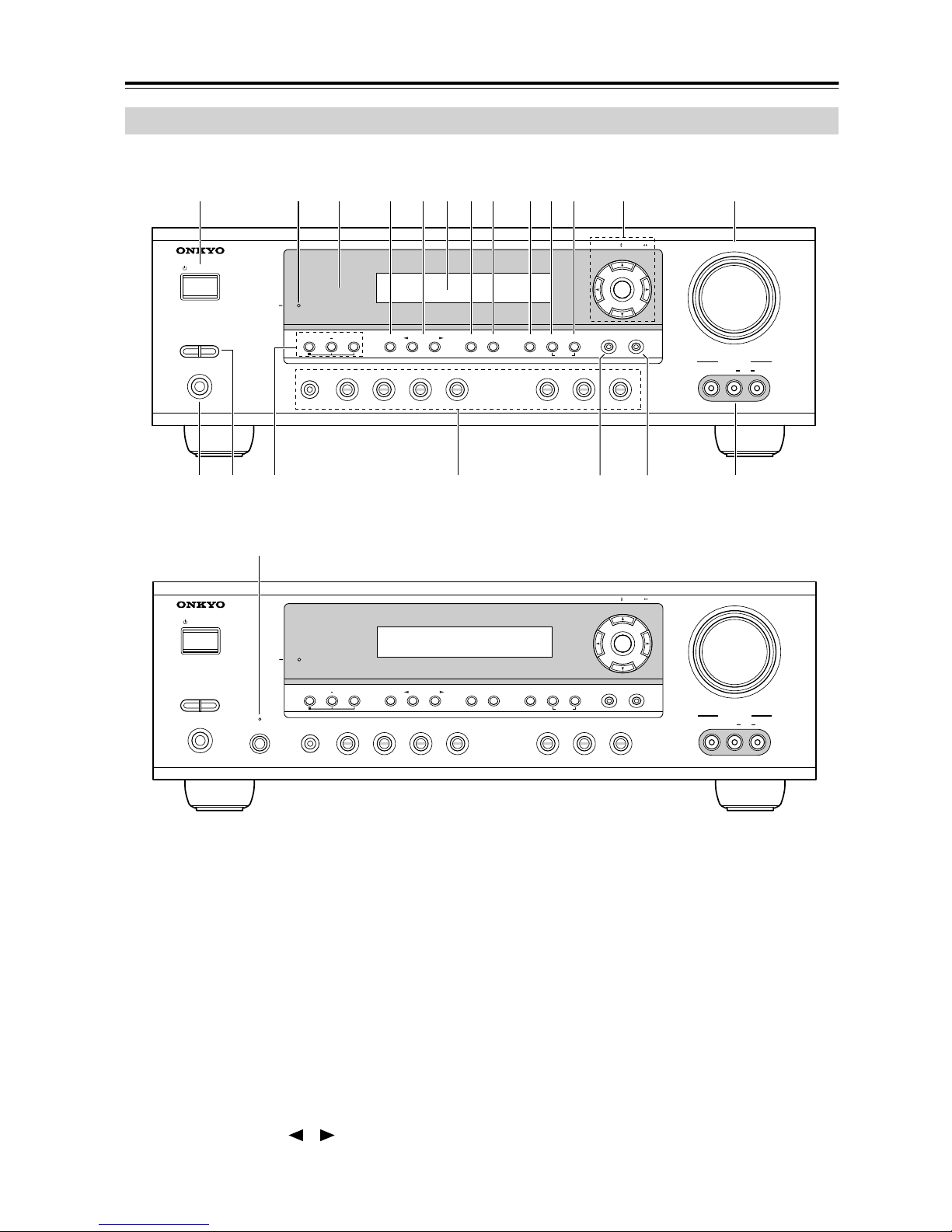
Front & Rear Panels
Front Panel
North American Model
1
STANDBY/ON
A SPEAKERS B
PHONES
Other Models
STANDBY/ON
U
3 4 5 7 8 9 J K L M6
2
STANDBY
TONE
MULTl CH DVD VIDEO 1 VIDEO 2
STANDBY
TUNING / PRESET
ENTER
RETURN
+
STEREO
LISTENING MODE
VCR
DISPLAY
DIGITAL INPUT
DIMMER MEMORY
TUNING MODE
CLEAR
VIDEO 3 TAPE TUNER CD
SETUP
MASTER VOLUME
VIDEO
VIDEO 3 INPUT
LR
AUDIO
TQN O P R S
TUNING / PRESET
ENTER
MASTER VOLUME
A SPEAKERS B
PHONES
PURE AUDIO
TONE
MULTl CH DVD VIDEO 1 VIDEO 2
+
STEREO
LISTENING MODE
VCR
For detailed information, see the pages in parentheses.
A STANDBY/ON button (32)
This button is used to set the AV receiver to On or
Standby.
B STANDBY indicator (32)
This indicator lights up when the AV receiver is in
Standby mode, and it flashes while a signal is being
received from the remote controller.
C Remote-control sensor (17)
This sensor receives control signals from the remote
controller.
D STEREO button (40)
This button is used to select the Stereo listening
mode.
E LISTENING MODE [ ]/[ ] buttons (40)
These buttons are used to select the listening modes.
DISPLAY
DIGITAL INPUT
VIDEO 3 TAPE TUNER CD
DIMMER
MEMORY
TUNING MODE
CLEAR
RETURN
F Display
See “Display” on page 9.
G DISPLAY button (35)
This button is used to display various information
about the currently selected input source.
H DIGITAL INPUT button (33)
This button is used to assign the digital inputs and to
specify the format of digital input signals.
I DIMMER button (38)
This button is used to adjust the display brightness.
J MEMORY button (37)
This button is used when storing or deleting radio
presets.
SETUP
VIDEO
VIDEO 3 INPUT
LR
AUDIO
8
Page 9
Front & Rear Panels—Continued
K TUNING MODE button (36)
This button is used to select the Auto or Manual tuning mode.
L Arrow/TUNING/PRESET & ENTER buttons
When the AM or FM input source is selected, the
TUNING [ ] [ ] buttons are used to tune the
tuner, and the PRESET [ ] [ ] buttons are used
to select radio presets (see page 36). When the setup
menus are used, they work as arrow buttons and are
used to select and set items. The ENTER button is
also used with the setup menus.
M MASTER VOLUME control (34)
This control is used to adjust the volume of the AV
receiver to MIN, 1 through 79, or MAX
N PHONES jack (39)
This 1/4-inch phone jack is for connecting a standard pair of stereo headphones for private listening.
O SPEAKER A & B buttons (34)
These buttons are used to turn speaker sets A and B
on or off.
P TONE, [–] & [+] buttons (38)
These buttons are used to adjust the bass and treble.
Q Input selector buttons (34)
These buttons are used to select from the following
input sources: MULTI CH, DVD, VIDEO 1,
VIDEO 2, VIDEO 3, TAPE, TUNER, or CD.
The [MULTI CH] button selects the DVD analog
multichannel input.
R RETURN button
This button is used to return to the previously displayed setup menu.
S SETUP button
This button is used to access various settings.
T VIDEO 3 INPUT (27, 51)
This input can be used to connect a camcorder,
games console, and so on. There are jacks for composite video and analog audio.
U PURE AUDIO button & indicator (40)
The North American model doesn’t have this button
and indicator.
This button is used to select the Pure Audio listening mode. The indicator lights up when that mode is
selected.
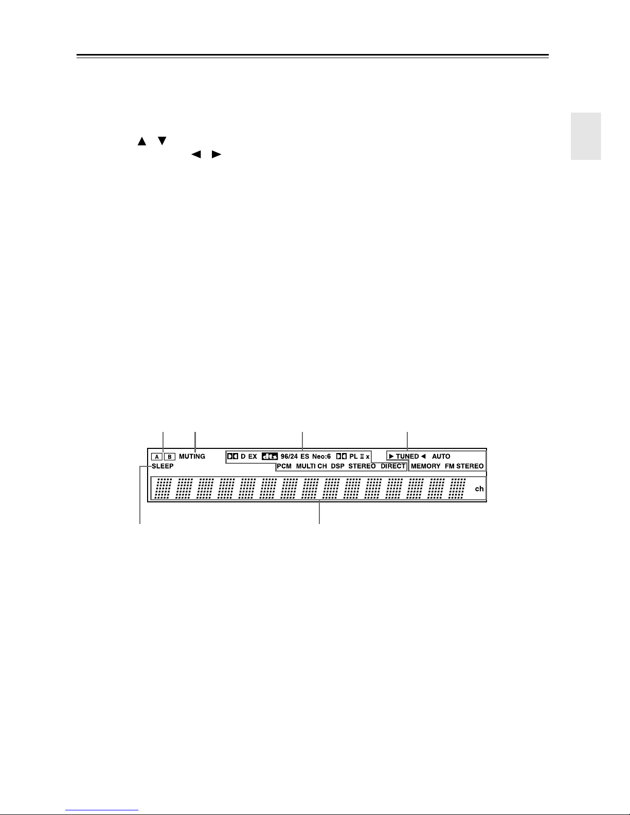
Display
2134
5
For detailed information, see the pages in parentheses.
1 A & B speaker indicators (34)
Indicator A lights up when speaker set A is on. Indicator B lights up when speaker set B is on.
2 MUTING indicator (38)
This indicator flashes when the AV receiver is
muted.
3 Source/listening mode indicators (42)
These indicators show the currently selected listening mode and digital audio format.
4 Tuning indicators (36)
6
MEMORY (37): This indicator lights up when presetting radio stations.
FM STEREO (36): This indicator lights up when
the AV receiver is tuned to a stereo FM station.
5 SLEEP indicator (39)
This indicator lights up when the Sleep function has
been set.
6 Message area
This area of the display shows various information
about the currently selected source.
TUNED (36):
receiver is tuned to a radio station.
AUTO (36): This indicator lights up when Auto
Tuning is selected and disappears when Manual
Tuning is selected.
This indicator lights up when the AV
9
Page 10
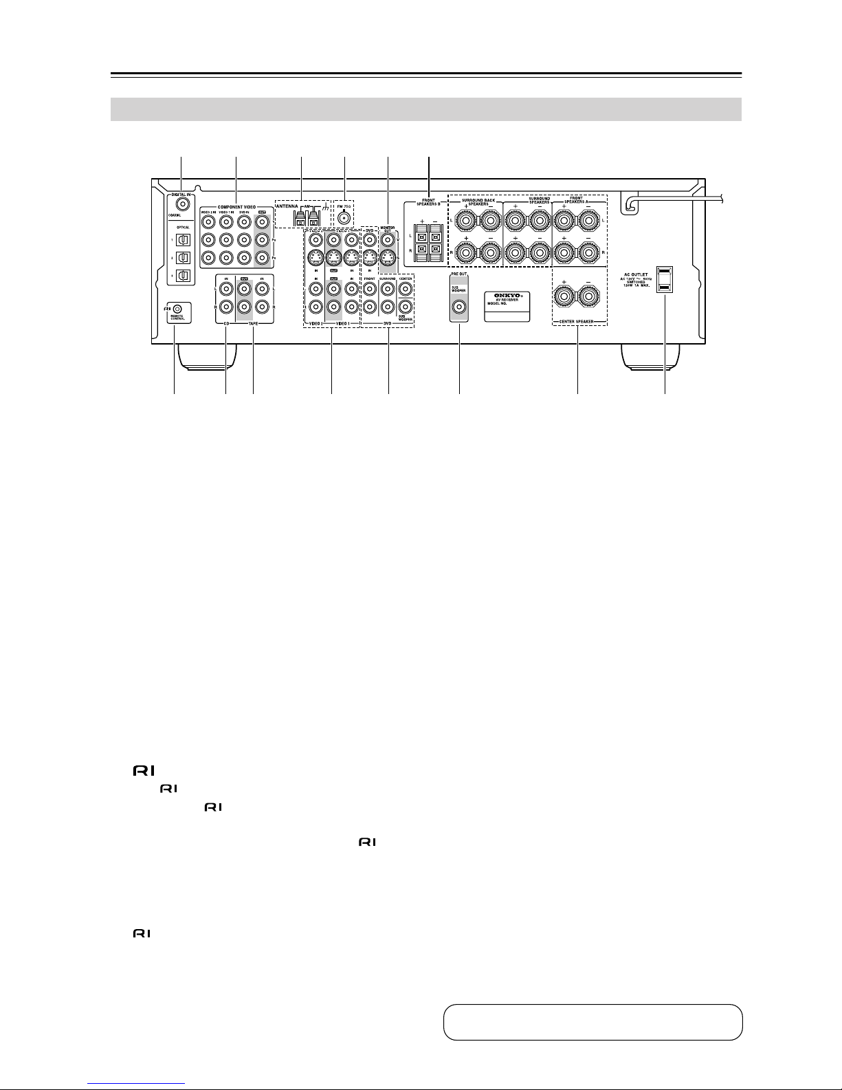
Front & Rear Panels—Continued
Rear Panel
1 B 3 4 65
7 8 9 J K L N
A DIGITAL IN OPTICAL 1, 2, 3 & COAXIAL
These optical and coaxial jacks can be used to connect a CD or DVD player and other components
with digital audio outputs.
B COMPONENT VIDEO
A DVD player, TV, or other component that supports component video can be connected here.
C AM ANTENNA
These push terminals are for connecting an AM
antenna.
D FM ANTENNA
This jack is for connecting an FM antenna.
E MONITOR OUT
The S-Video or composite video output should be
connected to a video input on your TV or projector.
F FRONT SPEAKERS B
These push terminals are for connecting speaker
set B.
G
This (Remote Interactive) jack can be connected to the jack on another Onkyo compo-
nent. The AV receiver’s remote controller can then
be used to control that component. To use , you
must make an analog audio connection (RCA)
between the AV receiver and the other component,
even if they are connected digitally.
Note:
can only be used with Onkyo components.
H CD IN
These analog inputs can be used to connect a CD
player with analog outputs.
M
I TAPE IN/OUT
These analog inputs and outputs can be used to connect a cassette recorder, MiniDisc recorder, or other
recorder with analog inputs and outputs.
J VIDEO 1 IN/OUT & VIDEO 2 IN
The VIDEO 1 S-Video, composite video, and audio
inputs and outputs can be used to connect a VCR.
The VIDEO 2 S-Video, composite video, and audio
inputs can be used to connect another video source
(e.g., cable TV, satellite TV, or a set-top box).
K DVD IN/MULTI CH INPUT
The FRONT, SURROUND, CENTER, and SUBWOOFER jacks can be used to connect a component with an analog multichannel audio output, such
as a DVD player with a 5.1-channel analog output.
The S-Video or composite video input should be
connected to a video output on the DVD player.
L SUBWOOFER PRE OUT
A powered subwoofer can be connected here.
M FRONT SPEAKERS A, SURROUND
SPEAKERS, CENTER SPEAKER &
SURROUND BACK SPEAKERS
These terminal posts are for connecting speaker
set A.
N AC OUTLET
This switched AC outlet can be used to supply
power to another component. The connector type
depends on the country in which you purchased
your AV receiver.
10
See pages 18–31 for connection information.
Page 11
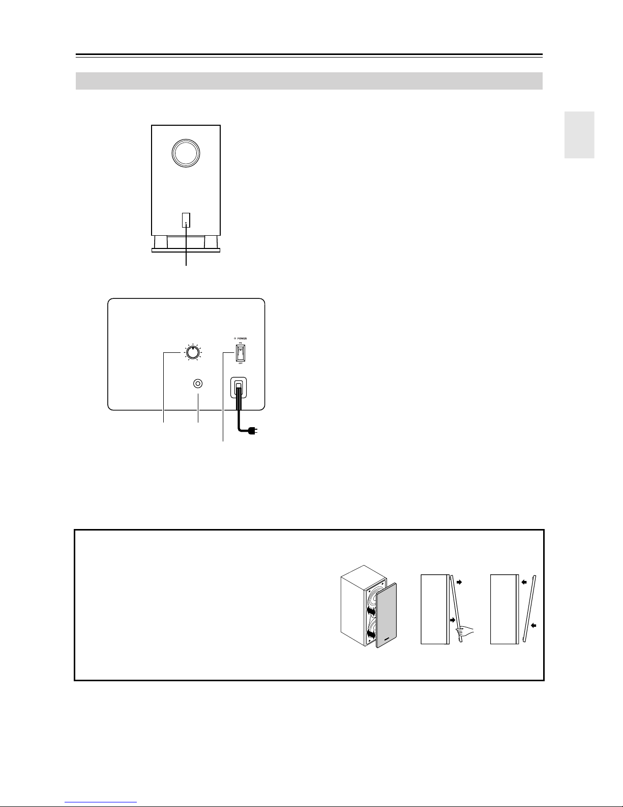
Front & Rear Panels—Continued
Subwoofer (SKW-530)
For detailed information, see the pages in parentheses.
■ Front
1
■ Rear
MIN
MAX
OUTPUT LEVEL
A STANDBY/ON indicator
Red: Subwoofer in standby mode
Green: Subwoofer on
With the Auto Standby function, the SKW-530
automatically turns on when an input signal is
detected in Standby mode. When there’s no input
signal for a while, the SKW-530 automatically
enters Standby mode.
B OUTPUT LEVEL control (34)
This control is used to adjust the volume of the subwoofer.
C LINE INPUT (19)
This RCA input should be connected to the subwoofer pre out on the AV receiver with supplied
RCA cable.
D POWER switch (Not North American model)
(32)
Press this switch to the ON position to turn on the
power. Press it to the OFF position to turn off the
power.
LINE INPUT
2
(Not North American model)
3
4
To AC outlet
■ Attaching and detaching the speaker grilles
Front and Center speakers have detachable grilles. Use the
following method to attach or detach the grilles.
1. While holding the bottom edge of the speaker grille with
your both hands, pull it gently toward you to remove the
bottom of the grille.
2. In the same way, gently pull the upper edge of the
speaker grille toward you to remove it from the main
unit.
3. To replace the grill, push the projections at the corners
into the grille plug holes on the speaker cabinet.
Note:
The Auto Standby function turns the subwoofer on when
the input signal exceeds a certain level. If the Auto
Standby function does not work reliably, try slightly
increasing or decreasing the subwoofer output level on
the AV receiver (page 47).
ReplacementRemoval
11
Page 12
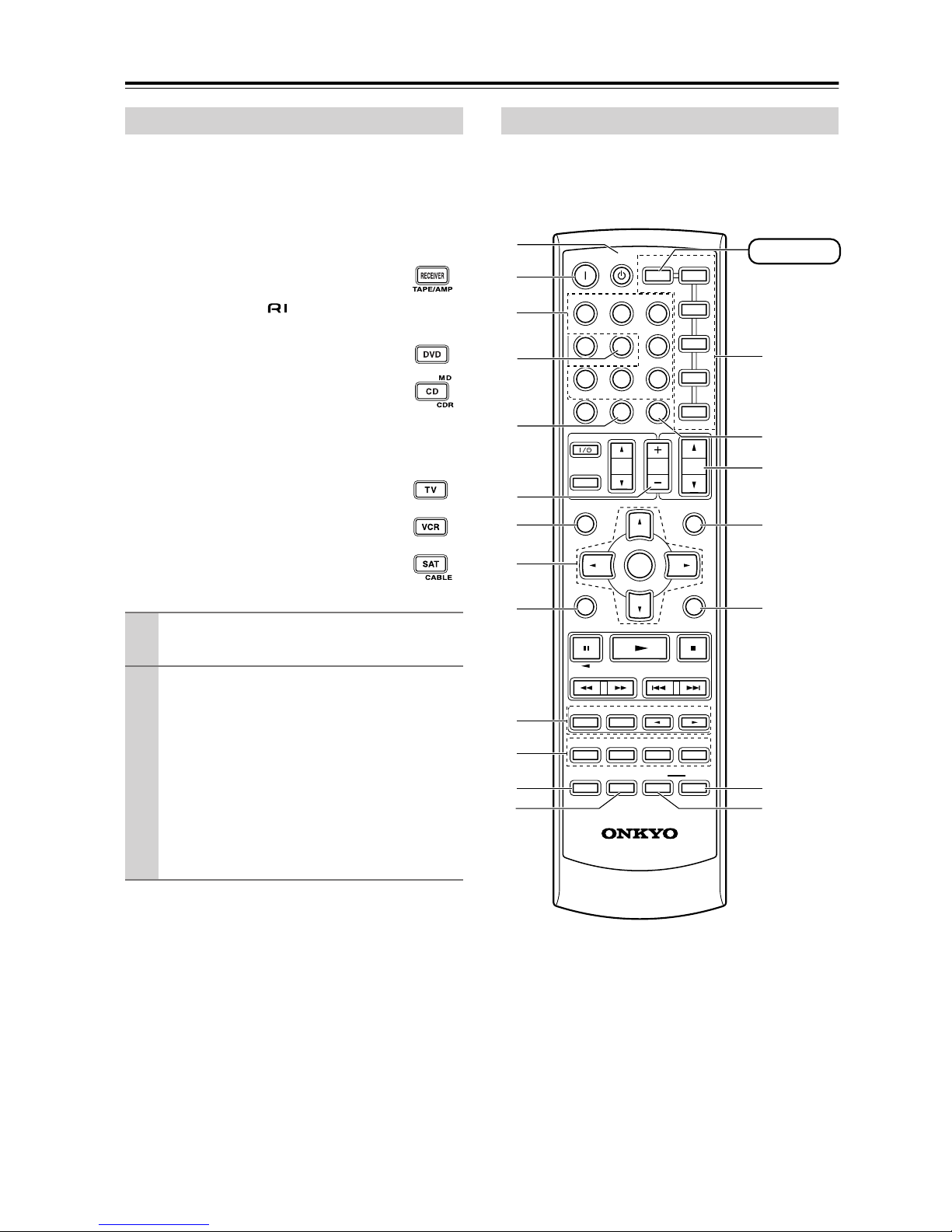
Remote Controller
How to Use the Remote Controller
Including the AV receiver, the remote controller can be
used to control up to seven different components. The
remote controller has a specific operating mode for use
with each type of component. Modes are selected by
using the six REMOTE MODE buttons.
■ RECEIVER/TAPE Mode
In RECEIVER/TAPE mode, you can control
the AV receiver and an Onkyo cassette
recorder connected via .
■ DVD & CD/MD/CDR Modes
With these modes, you can control a DVD
player and CD/MD/CDR player/recorder.
By entering the appropriate remote control
code, you can control Onkyo components or
components made by other manufacturers
(see page 52).
■ TV, VCR & SAT/CABLE Modes
With these modes, you can control a TV,
VCR, and satellite/cable receiver. You must
enter the appropriate remote control code
first (see page 52).
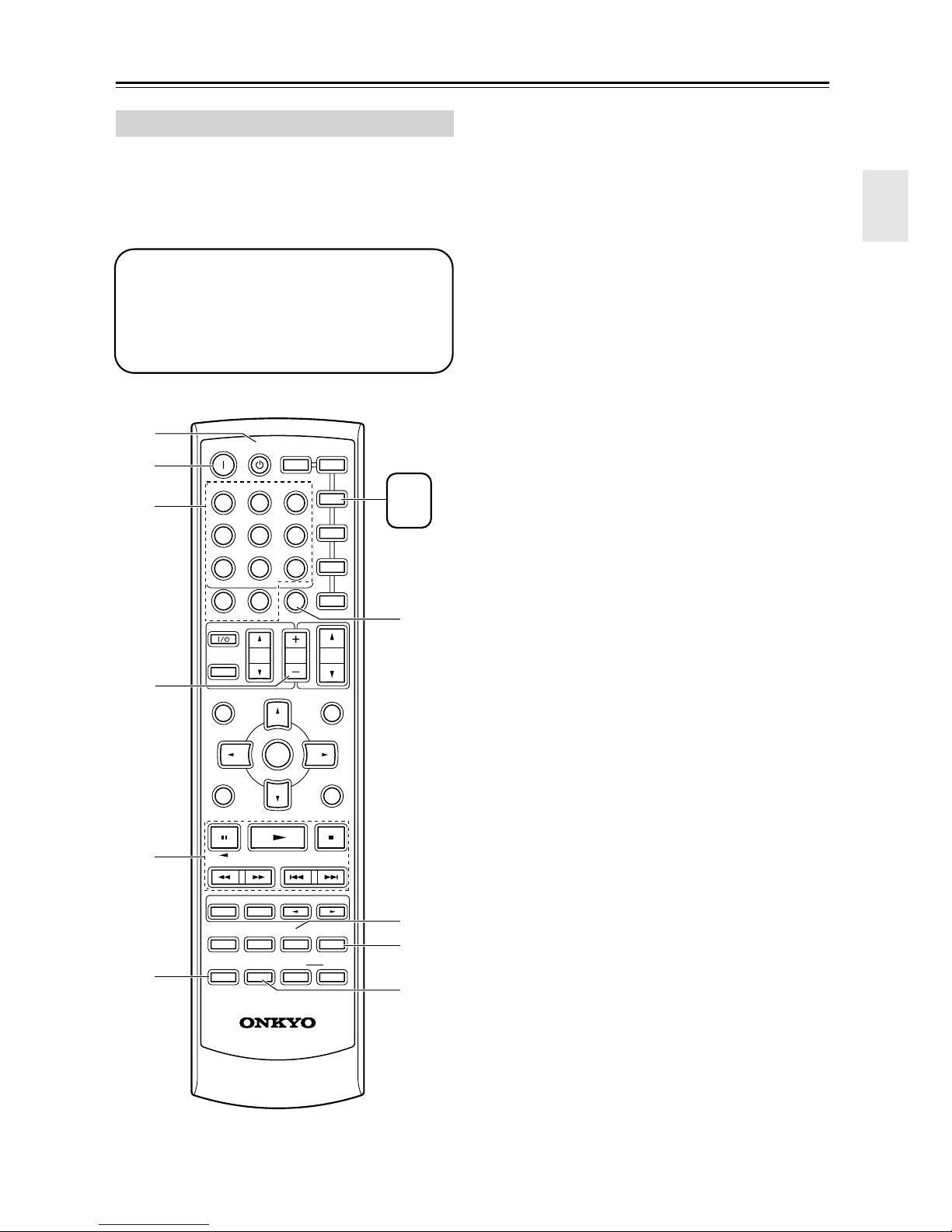
RECEIVER Mode
RECEIVER mode is used to control the AV receiver.
To set the remote controller to RECEIVER mode,
press the [RECEIVER] REMOTE MODE button.
A
B
C
D
E
F
G
H
ON STANDBY
INPUT SELECTOR
123
V
1
456
789
+
10
10 11 12
--/---
TV
INPUT
GUIDE
TOP MENU
SP A/ B
REMOTE MODE
RECEIVER
TAPE/AMP
V
2
MULTI CH
0
DIMMER SLEEP
VOL
ENTER
V
DVD
CDTAPE TUNER
CLR
CH
DISC
3
DVD
CD
TV
VCR
SAT
CABLE
VOL
PREVIOUS
MENU
MUTING
MD
CDR
RECEIVER
N
O
P
Q
Use the REMOTE MODE buttons to select
1
a mode.
Use the buttons supported by that mode
2
to control the component.
RECEIVER mode: see page 12
DVD mode: see page 14
CD/MD/CDR mode: see page 15
TAPE mode: see page 16
TV mode: see page 54
see page 16 for TV
control buttons
VCR, SAT/CABLE mode: see page 54
Note:
Some of the remote controller operations described in
this manual may not work as expected with other components.
I
J
K
L
M
SETUPRETURN
LISTENING MODE
SURROUND
STEREO
RANDOM
SUBTITLE
AUDIO REPEAT
TEST TONE
CH SEL
PLAY MODE
DISPLAY
OR-EQ
-
LEVEL
LEVEL
DVDHDD
CINE FLTR
L NIGHT
-
608M
RC
R
+
S
T
12
Page 13

Remote Controller—Continued
For detailed information, see the pages in parentheses.
A STANDBY button (32)
This button is used to set the AV receiver to
Standby.
B ON button (32)
This button is used to turn on the AV receiver.
C INPUT SELECTOR buttons (34)
These buttons are used to select the input sources.
D MULTI CH button (35)
This button is used to select the multichannel DVD
input.
E DIMMER button (38)
This button is used to adjust the display brightness.
F CH +/– button (37)
This button is used to select radio presets.
G SP A/B button (34)
This button is used to turn speaker sets A and B on
or off.
H Arrow [ ]/[ ]/[ ]/[ ] & ENTER buttons
These buttons are used to select and adjust settings.
I RETURN button
This button is used to return to the previous display
when changing settings.
J LISTENING MODE buttons (40)
These buttons can be used to select listening modes
regardless of the currently selected remote controller mode.
STEREO button
This button selects the Stereo listening mode.
SURROUND button
This button selects the Dolby and DTS listening
modes.
[ ]/[ ] buttons
These buttons can be used to select any of the available listening modes.
K TEST TONE, CH SEL, LEVEL- & LEVEL+
buttons (32)
These buttons are used to adjust the level of each
speaker.
L DISPLAY button (35, 52)
This button is used to display various information
about the currently selected input source.
M OR-EQ button (38)
This button is used to turn on the OptiResponse
equalizer, which optimizes performance when the
HT-R530 is used with the speakers included in this
Speaker Package. When the OptiResponse equalizer
is on, you can enjoy a powerful sound with movies
or music with small volume.
N REMOTE MODE buttons (12)
These buttons are used to select the remote controller modes. When you press a button on the remote
controller, the REMOTE MODE button for the currently selected mode lights up.
O SLEEP button (39)
This button is used to set the Sleep function.
P VOL [ ]/[ ] button (34)
This button can be used to adjust the volume of the
AV receiver regardless of the currently selected
remote controller mode.
Q MUTING button (38)
This button is used to mute the AV receiver.
R SETUP button
This button is used to access various settings.
S CINE FLTR button (44)
This button is used to set the CinemaFILTER function.
T L NIGHT button (44)
This button is used to set the Late Night function.
13
Page 14
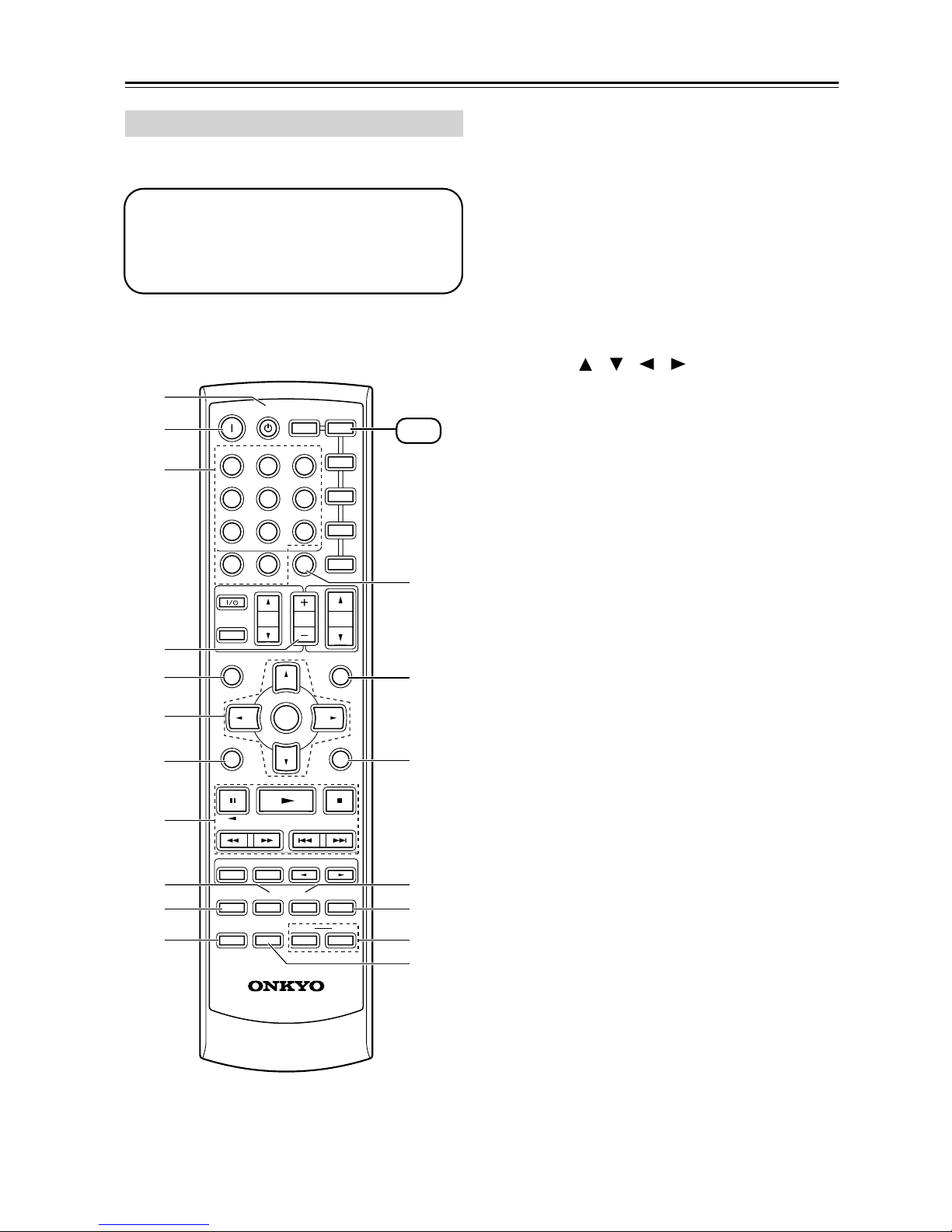
Remote Controller—Continued
DVD Mode
To set the remote controller to DVD mode, press the
[DVD] REMOTE MODE button.
Before selecting DVD mode and starting playback, you should press the [RECEIVER] mode
button followed by the [DVD] INPUT SELECTOR button to select the DVD player as the
input source.
A
B
C
D
E
F
G
ON STANDBY
INPUT SELECTOR
123
V
1
456
789
+
10
10 11 12
--/---
TV
INPUT
GUIDE
TOP MENU
SP A/ B
RECEIVER
TAPE/AMP
V
2
MULTI CH
0
DIMMER SLEEP
VOL
ENTER
REMOTE MODE
V
DVD
CDTAPE TUNER
CLR
CH
DISC
3
DVD
CD
TV
VCR
SAT
CABLE
VOL
PREVIOUS
MENU
MUTING
SETUPRETURN
CDR
DVD
M
D
L
M
N
H
LISTENING MODE
SURROUND
I
J
K
STEREO
RANDOM
SUBTITLE
AUDIO REPEAT
TEST TONE
CH SEL
PLAY MODE
DISPLAY
OR-EQ
LEVEL
L NIGHT
-
LEVEL
DVDHDD
CINE FLTR
+
O
P
Q
R
-
RC
608M
A STANDBY button
This button sets the DVD player to Standby.
B ON button
This button is used to turn on the DVD player.
C Number buttons
These buttons are used to enter title, chapter, and
track numbers and to enter times for locating specific points in time.
D DISC +/– button
This button selects discs on a DVD changer.
E TOP MENU button
This button is used to select a DVD’s top menu.
F Arrow [ ]/[ ]/[ ]/[ ] & ENTER buttons
These buttons are used to navigate DVD menus and
the DVD player’s onscreen setup menus.
G RETURN button
This button is used to exit the DVD player’s
onscreen setup menu and to restart menu playback.
H Playback buttons
From left to right: Pause, Play, Stop, Fast Reverse,
Fast Forward, Previous, and Next.
I SUBTITLE button
This button is used to select subtitles.
J AUDIO button
This button selects foreign language soundtracks
and audio formats (e.g., Dolby Digital or DTS).
K DISPLAY button
This button is used to display information about the
current disc, title, chapter, or track on the DVD
player’s display, including the elapsed time, remaining time, total time, and so on.
L CLR button
This button is used to cancel functions and to clear
entered numbers.
M MENU button
This button is used to display a DVD’s menu.
N SETUP button
This button is used to access the DVD player’s
onscreen setup menus.
O RANDOM button
This button is used with the random playback function.
P REPEAT button
This button is used to set the repeat playback functions.
Q HDD & DVD buttons
These buttons are used to select hard disk (HDD) or
DVD playback on a DVD recorder with a built-in
hard disk drive.
R PLAY MODE button
This button is used to select play modes on a component with selectable play modes.
14
Page 15
Remote Controller—Continued
CD/MD/CDR Mode
By default, the AV receiver is configured to control an
Onkyo CD player.
To set the remote controller to CD/MD/CDR mode,
press the [CD] REMOTE MODE button.
Before selecting CD/MD/CDR mode and starting playback, you should press the
[RECEIVER] mode button followed by the [CD]
or [TAPE] INPUT SELECTOR button to select
the CD player, MiniDisc, or CD recorder as the
input source.
A
B
C
D
ON STANDBY
INPUT SELECTOR
123
V
1
456
789
+
10
10 11 12
--/---
TV
INPUT
GUIDE
TOP MENU
SP A/ B
REMOTE MODE
RECEIVER
TAPE/AMP
V
2
MULTI CH
0
DIMMER SLEEP
VOL
ENTER
V
DVD
CDTAPE TUNER
CLR
CH
DISC
3
DVD
CD
TV
VCR
SAT
CABLE
VOL
PREVIOUS
MENU
MUTING
CDR
D
M
MD
CD
CDR
G
A STANDBY button
This button sets the CD player or MD/CD recorder
to Standby.
B ON button
This button is used to set the CD player or MD/CD
recorder to On or Standby.
C Number buttons
These buttons are used to enter track numbers and
to enter times for locating specific points in time.
D DISC +/– button
This button selects discs on a CD changer.
E Playback buttons
From left to right: Pause, Play, Stop, Fast Reverse,
Fast Forward, Previous and Next.
F DISPLAY button
This button is used to display information about the
current disc or track on the CD player or MD/CD
recorder’s display, including the elapsed time,
remaining time, total time, and so on.
G CLR button
This button is used to cancel functions and to clear
entered numbers.
H RANDOM button
This button is used with the random playback function.
I REPEAT button
This button is used to set the repeat playback functions.
J PLAY MODE button
This button is used to select play modes on a component with selectable play modes.
E
LISTENING MODE
SURROUND
STEREO
RANDOM
SUBTITLE
AUDIO REPEAT
TEST TONE
CH SEL
PLAY MODE
DISPLAY
F
OR-EQ
-
LEVEL
L NIGHT
-
RC
608M
SETUPRETURN
LEVEL
DVDHDD
CINE FLTR
8
+
9
J
15
Page 16
Remote Controller—Continued
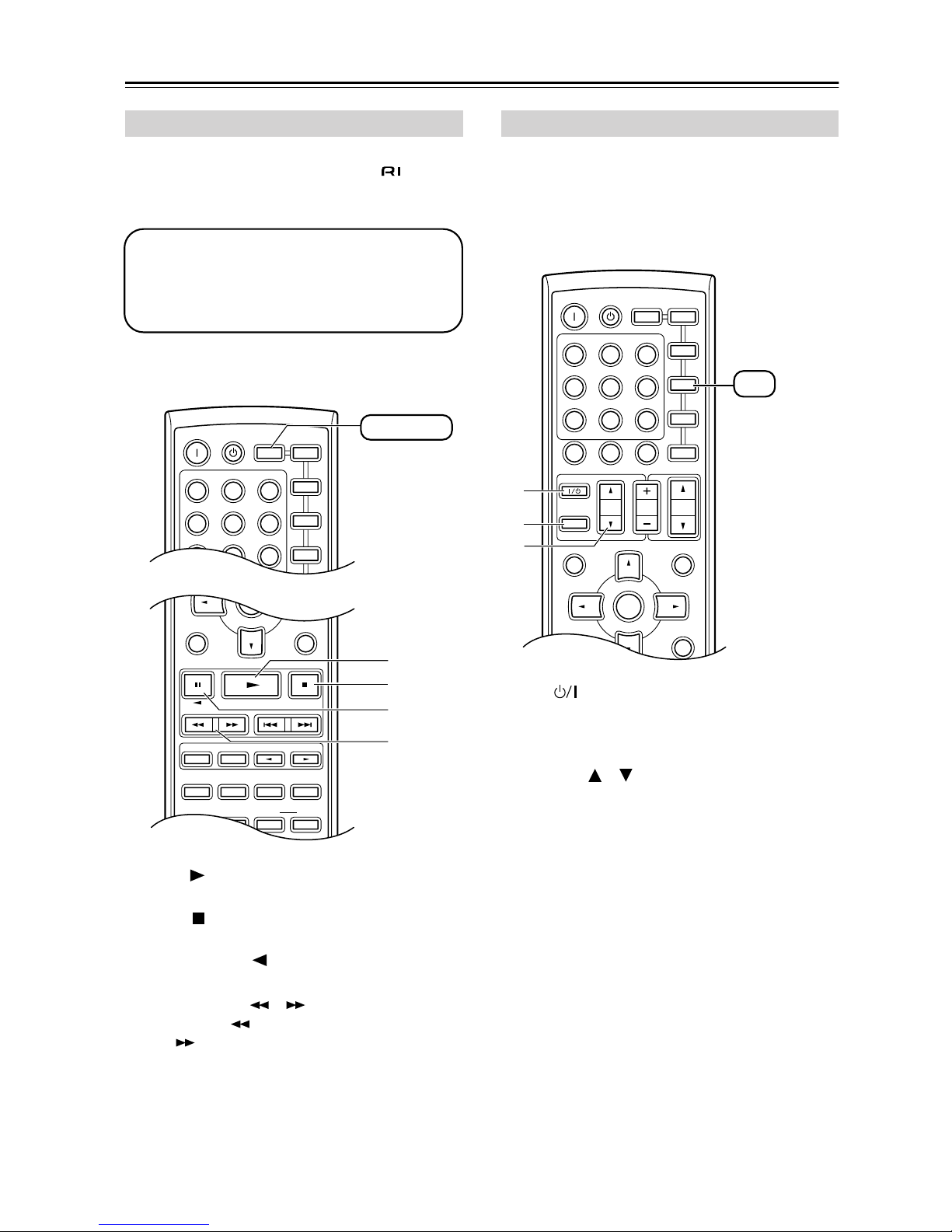
TAPE Mode
TAPE mode is used to control an Onkyo cassette
recorder connected to the AV receiver via .
To set the remote controller to TAPE mode, press the
[RECEIVER] REMOTE MODE button.
Before selecting TAPE mode and starting playback, you should press the [RECEIVER]
REMOTE MODE button followed by the [TAPE]
INPUT SELECTOR button to select your cassette recorder as the input source.
For twin cassette decks, only deck B can be controlled.
ON STANDBY
INPUT SELECTOR
123
V
1
456
789
V
2
MULTI CH
REMOTE MODE
RECEIVER
TAPE/AMP
V
DVD
CDTAPE TUNER
ENTER
3
DVD
CD
TV
VCR
MD
CDR
RECEIVER
TV Control Buttons
The remote controller has dedicated buttons for controlling a TV, which can be used regardless of which remote
controller mode is currently selected. To use these buttons, you must first program the [TV] mode button with
the remote control code appropriate for the TV (see
page 52).
A
B
C
ON STANDBY
INPUT SELECTOR
123
V
1
456
789
+
10
10 11 12
--/---
TV
INPUT
GUIDE
TOP MENU
SP A/ B
REMOTE MODE
RECEIVER
TAPE/AMP
V
2
MULTI CH
0
DIMMER SLEEP
VOL
ENTER
V
DVD
CDTAPE TUNER
CLR
CH
DISC
DVD
MD
CD
CDR
3
TV
VCR
SAT
CABLE
TV
You must enter
the appropriate
remote control
code (see
page 52)
VOL
PREVIOUS
MENU
MUTING
SETUPRETURN
A
B
C
LISTENING MODE
SURROUND
STEREO
SUBTITLE
AUDIO REPEAT
TEST TONE
DISPLAY
CH SEL
PLAY MODE
OR-EQ
RANDOM
LEVEL
L NIGHT
+
-
LEVEL
DVDHDD
CINE FLTR
A Play [ ] button
This button is used to start playback.
B Stop [ ] button
This button is used to stop playback.
C Reverse Play [ ] button
This button is used to start reverse playback.
D Rewind & FF [ ]/[ ] buttons
The Rewind [ ] button is used to start rewind. The
FF [ ] button is used to start fast forward.
D
SETUPRETURN
A TV [ ]
This sets the TV to On or Standby.
B [TV INPUT]
This selects inputs on the TV.
C TV VOL [ ]/[ ]
This adjusts the TV’s volume.
16
Page 17
Before Using the AV receiver
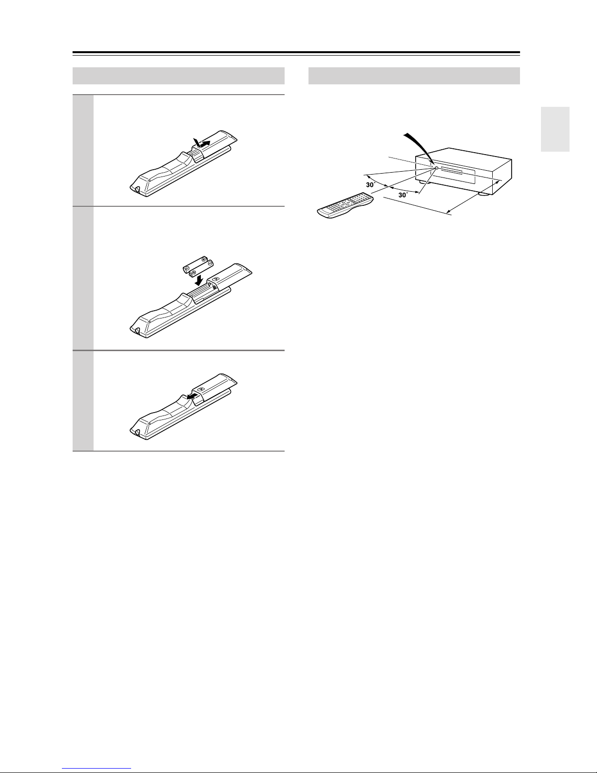
Installing the Batteries
To open the battery compartment, press
1
the small hollow and slide open the cover.
Insert the two supplied batteries (AA/R6)
2
in accordance with the polarity diagram
inside the battery compartment.
Slide the cover shut.
3
Using the Remote Controller
To use the remote controller, point it at the AV receiver’s
remote control sensor, as shown below.
Remote control sensor
AV receiver
STANDBY indicator
Approx. 16 ft.
(5 m)
Notes:
• The remote controller may not work reliably if the AV
receiver is subjected to bright light, such as direct sunlight or inverter-type fluorescent lights. Keep this in
mind when installing.
• If another remote controller of the same type is used in
the same room, or the AV receiver is installed close to
equipment that uses infrared rays, the remote controller may not work reliably.
• Don’t put anything, such as a book, on the remote controller, because the buttons may be pressed inadvertently, thereby draining the batteries.
• The remote controller may not work reliably if the AV
receiver is installed in a rack behind colored glass
doors. Keep this in mind when installing.
• The remote controller will not work if there’s an obstacle between it and the AV receiver’s remote control
sensor.
Notes:
• The batteries should last for about six months,
although this will vary with usage.
• If the remote controller doesn’t work reliably, try
replacing the batteries.
• Don’t mix new and old batteries or different types of
batteries.
• If you intend not to use the remote controller for a long
time, remove the batteries to prevent damage from
leakage or corrosion.
• Expired batteries should be removed as soon as possible to prevent damage from leakage or corrosion.
17
Page 18
Connecting Speakers
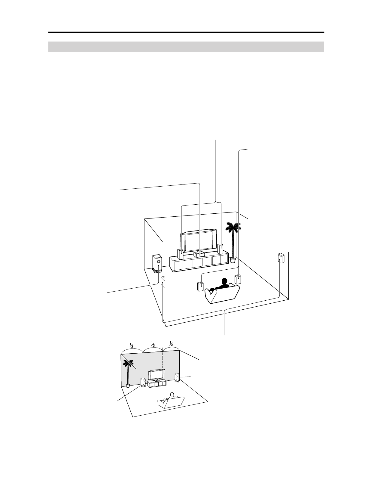
Enjoying Home Theater
You can use two sets of speakers with the AV receiver: speaker set A and speaker set B.
Speaker set A (supplied speakers and subwoofer) should be installed in your main listening room and can be used with
Dolby Digital and DTS surround material. Each speaker must be positioned at a specific location in your listening room
to get the best from surround sound material. The following illustration shows the best positions for your surroundsound speakers. When speaker set B is turned on, speaker set A is reduced to 5.1-channel playback.
Speaker set B can be installed in another room. Speakers can be positioned in the standard position for stereo speakers
or however you like. Speaker set B outputs only analog input signals.
Front left and right speakers (SKF-530 FL/FR)
These output the overall sound. Their role in a home theater is to provide a solid anchor for
the sound image. They should be positioned facing the listener at about ear level, and equidistant from the TV. Angle them inward so as to create a triangle, with the listener at the apex.
Surround back left and right
speakers (SKB-530)
These speakers further
enhance the realism of surround sound and improve
sound localization behind the
Center speaker (SKC-530C)
This speaker enhances the front left
and right speakers, making sound
movements distinct and providing a
full sound image. In movies it’s used
mainly for dialog.
Position it close to your TV (preferably
on top) facing forward at about ear
level, or at the same height as the
front left and right speakers.
listener. They are essential to
enjoy certain listening modes
(i.e., Dolby Digital EX and
DTS-ES). Position them
behind the listener about 2–
3 feet (60–100 cm) above ear
level. Make sure that the listening position is within the
range of the speaker.
Subwoofer (SKW-530)
The subwoofer handles the bass sounds of
the LFE (Low-Frequency Effects) channel.
The volume and quality of the bass output
from your subwoofer will depend on its position, the shape of your listening room, and
your listening position. In general, a good
bass sound can be
obtained by installing the
subwoofer in a front corner,
or at one-third the width of
the wall, as shown.
1/3 wall
length
To get the very best from your surround-sound system, you should also specify the distance between the listener and
each individual speaker so that the sound from each speaker arrives at the listener’s ears at the same time (see page 46).
In addition, you should set the level of each individual speaker to achieve an equal balance (see page 47.)
18
Corner
Surround left and right speakers
(SFM-530 SL/SR)
These speakers are used for precise sound
positioning and to add realistic ambience.
Position them at the sides of the listener, or
slightly behind, about 2–3 feet (60–100 cm)
above ear level. Ideally they should be equidistant from the listener.
Page 19
Connecting Speakers—Continued
Speaker Connection Precautions
Read the following before connecting your speakers:
• You can connect speakers with an impedance of
8 ohms or higher. If you use speakers with a lower
impedance, and use the amplifier at high volume levels for a long period of time, the built-in protection
circuit may be activated.
• Disconnect the power cord from the wall outlet before
making any connections.
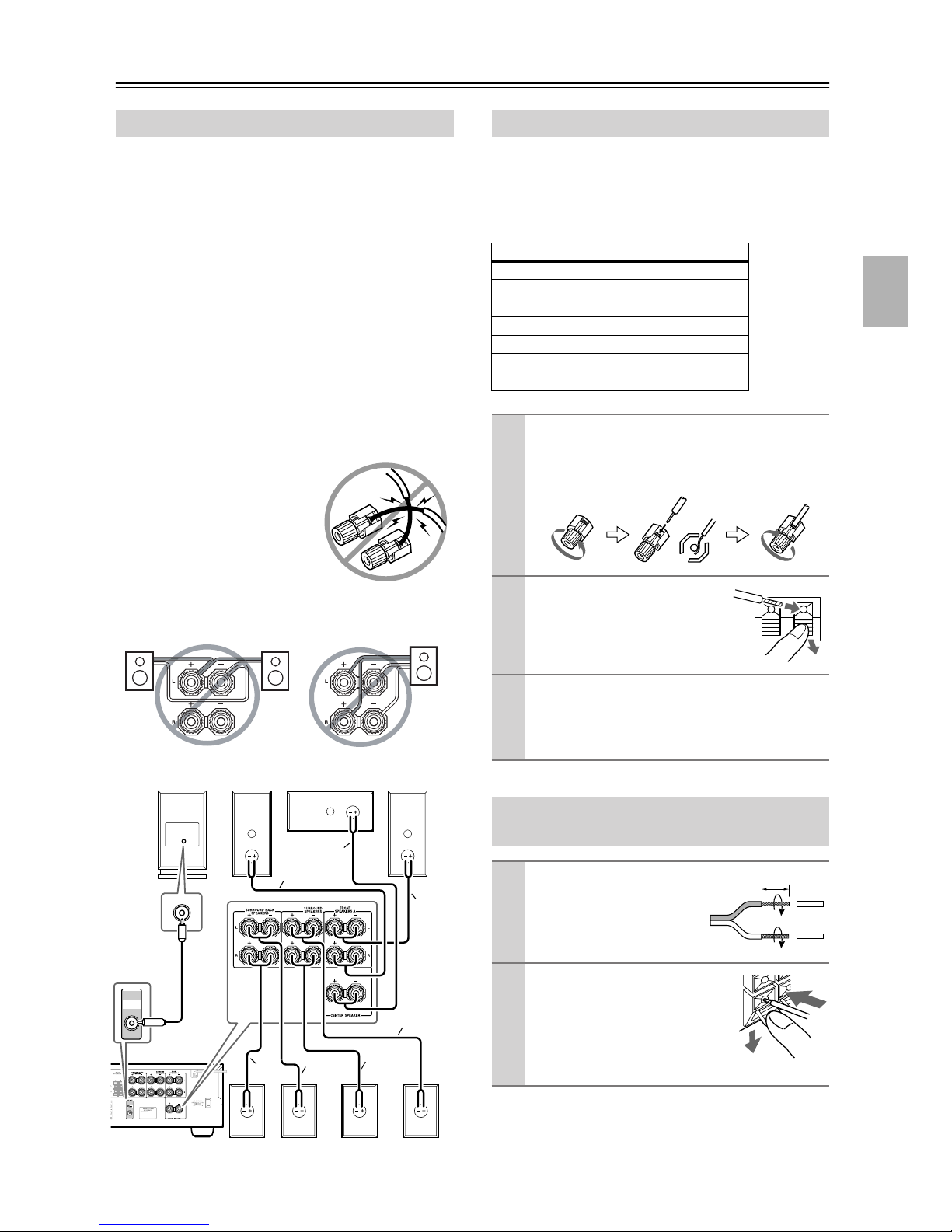
• Pay close attention to speaker wiring polarity. In other
words, connect positive (+) terminals to only positive
(+) terminals, and negative (–) terminals to only negative (–) terminals. If you get them the wrong way
around, the sound will be out of phase and will sound
unnatural.
• Unnecessarily long, or very thin speaker cables may
affect the sound quality and should be avoided.
• Be careful not to short the
positive and negative wires.
Doing so may damage the AV
receiver.
• Don’t connect more than one
cable to each speaker terminal. Doing so may damage the
AV receiver.
• Don’t connect one speaker to several terminals.
Connecting Speaker Set A
The AV receiver’s positive (+) speaker terminals and
speaker’s positive (+) terminals are color-coded for ease
of identification. (The negative (–) speaker terminals are
all black.) Match the color of each cable to the corresponding speaker terminal.
Speaker terminal Color
Front left White
Front right Red
Center Green
Surround left Blue
Surround right Gray
Surround back left Brown
Surround back right Tan
On the AV receiver, unscrew the terminal. Fully
1
insert the bare wires. Make sure that the bare wire
is touching the inside of the pole. Screw the terminal tight.
On the speakers, while pressing
2
the terminal lever, insert the
wire into the hole, and then
release the lever.
PRE OUT
SUB
WOOFER
SKW-530
SKF-530FR
Ta n
Red
SKB-530LSKB-530R
SKC-530C
Green
Brown
SKM-530SR
SKF-530FL
Gray
White
Blue
SKM-530SL
Using the supplied RCA cable, connect the AV
3
receiver’s SUBWOOFER PRE OUT to LINE
INPUT on the subwoofer.
Make sure the cable is plugged all the way.
Connecting Speaker Set B (sold
separately)
Strip 3/8" (10 mm) of insu-
1
lation from the ends of the
speaker cables, and twist
the bare wires tightly, as
shown.
While pressing the lever, insert
2
the wire into the hole, and then
release the lever.
Make sure that the terminals are
gripping the bare wires, not the
insulation.
Note:
When speaker set B is turned on, speaker set A is reduced
to 5.1-channel playback.
3/8" (10 mm)
19
Page 20
Connecting Antenna
This section explains how to connect the supplied indoor
FM antenna and AM loop antenna, and how to connect
commercially available outdoor FM and AM antennas.
The AV receiver won’t pick up any radio signals without
any antenna connected, so you must connect the antenna
to use the tuner.
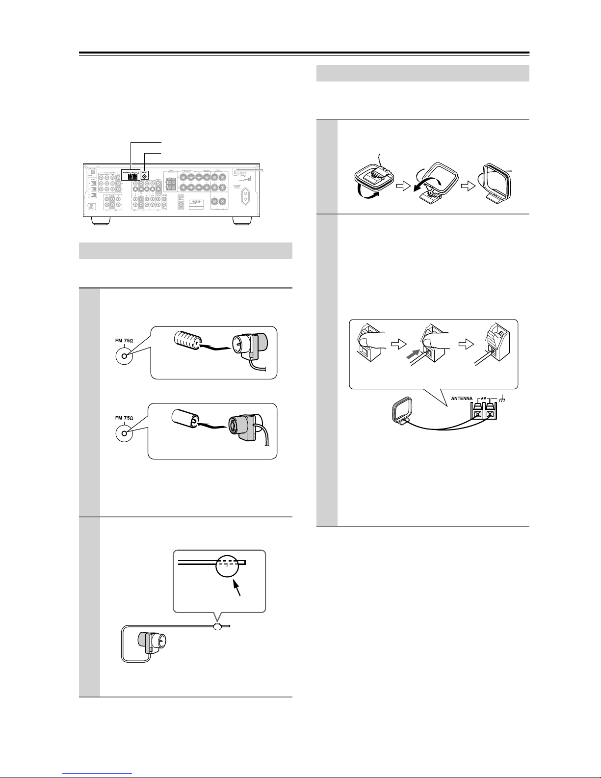
AM antenna push terminals
FM antenna jack
Connecting the Indoor FM Antenna
The supplied indoor FM antenna is for indoor use only.
Attach the FM antenna, as shown.
1
■ American Model
Connecting the AM Loop Antenna
The supplied indoor AM loop antenna is for indoor use
only.
Assemble the AM loop antenna, inserting
1
the tabs into the base, as shown.
Connect both wires of the AM loop
2
antenna to the AM push terminals, as
shown.
(The antenna’s wires are not polarity sensitive, so
they can be connected either way around).
Make sure that the wires are attached securely and
that the push terminals are gripping the bare
wires, not the insulation.
Insert the plug fully
into the jack.
■ Other Models
Insert the plug fully
into the jack.
Once your AV receiver is ready for use, you’ll
need to tune into an FM radio station and adjust
the position of the FM antenna to achieve the best
possible reception.
Use thumbtacks or something similar to
2
fix the FM antenna into position.
Thumbtacks, etc.
Push Insert wire Release
Once your AV receiver is ready for use, you’ll
need to tune into an AM radio station and adjust
the position of the AM antenna to achieve the best
possible reception.
Keep the antenna as far away as possible from
your AV receiver, TV, speaker cables, and power
cords.
If you cannot achieve good reception with the supplied
indoor AM loop antenna, try using it with a commercially available outdoor AM antenna (see page 21).
Caution: Be careful that you don’t injure yourself
when using thumbtacks.
If you cannot achieve good reception with the supplied
indoor FM antenna, try a commercially available outdoor FM antenna instead (see page 21).
20
Page 21
Connecting Antenna—Continued
Connecting an Outdoor FM Antenna
If you cannot achieve good reception with the supplied
indoor FM antenna, try a commercially available outdoor FM antenna instead.
Notes:
• Outdoor FM antennas work best outside, but usable
results can sometimes be obtained when installed in an
attic or loft.
• For best results, install the outdoor FM antenna well
away from tall buildings, preferably with a clear line
of sight to your local FM transmitter.
• Outdoor antenna should be located away from possible noise sources, such as neon signs, busy roads, etc.
• For safety reasons, outdoor antenna should be situated
well away from power lines and other high-voltage
equipment.
• Outdoor antenna must be grounded in accordance
with local regulations to prevent electrical shock hazards.
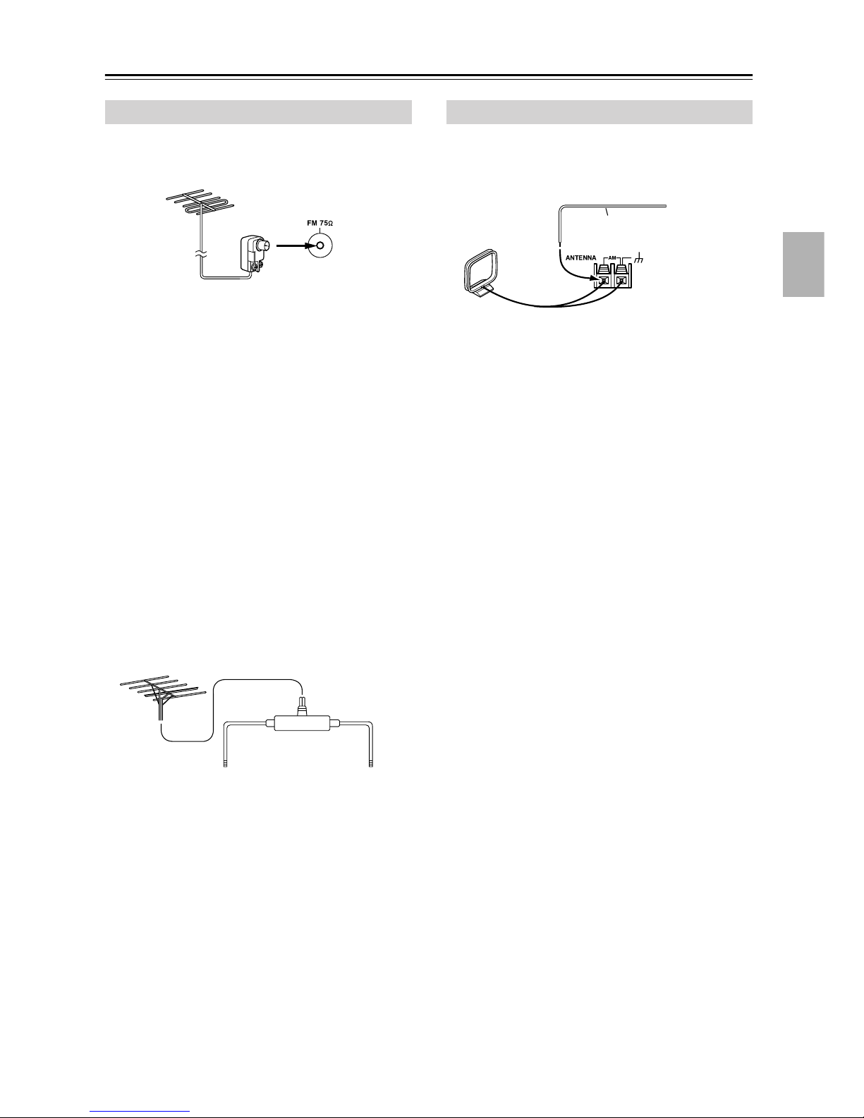
Connecting an Outdoor AM Antenna
If good reception cannot be achieved using the supplied
AM loop antenna, an outdoor AM antenna can be used in
addition to the loop antenna, as shown.
Outdoor antenna
Insulated antenna cable
AM loop antenna
Outdoor AM antennas work best when installed outside
horizontally, but good results can sometimes be obtained
indoors by mounting horizontally above a window. Note
that the AM loop antenna should be left connected.
Outdoor antenna must be grounded in accordance with
local regulations to prevent electrical shock hazards.
■ Using a TV/FM Antenna Splitter
It’s best not to use the same antenna for both FM and TV
reception, as this can cause interference problems. If circumstances demand it, use a TV/FM antenna splitter, as
shown.
TV/FM antenna splitter
To AV receiver To TV (or VCR)
21
Page 22
Connecting Your Components
About AV Connections
• Before making any AV connections, read the manuals
supplied with your other AV components.
• Don’t connect the power cord until you’ve completed
and double-checked all AV connections.
Optical Digital Jacks
The AV receiver’s optical digital jacks have shutter-type
covers that open when an optical plug is inserted and
close when it’s removed. Push plugs in all the way.
Caution: To prevent shutter damage, hold the optical
plug straight when inserting and removing.
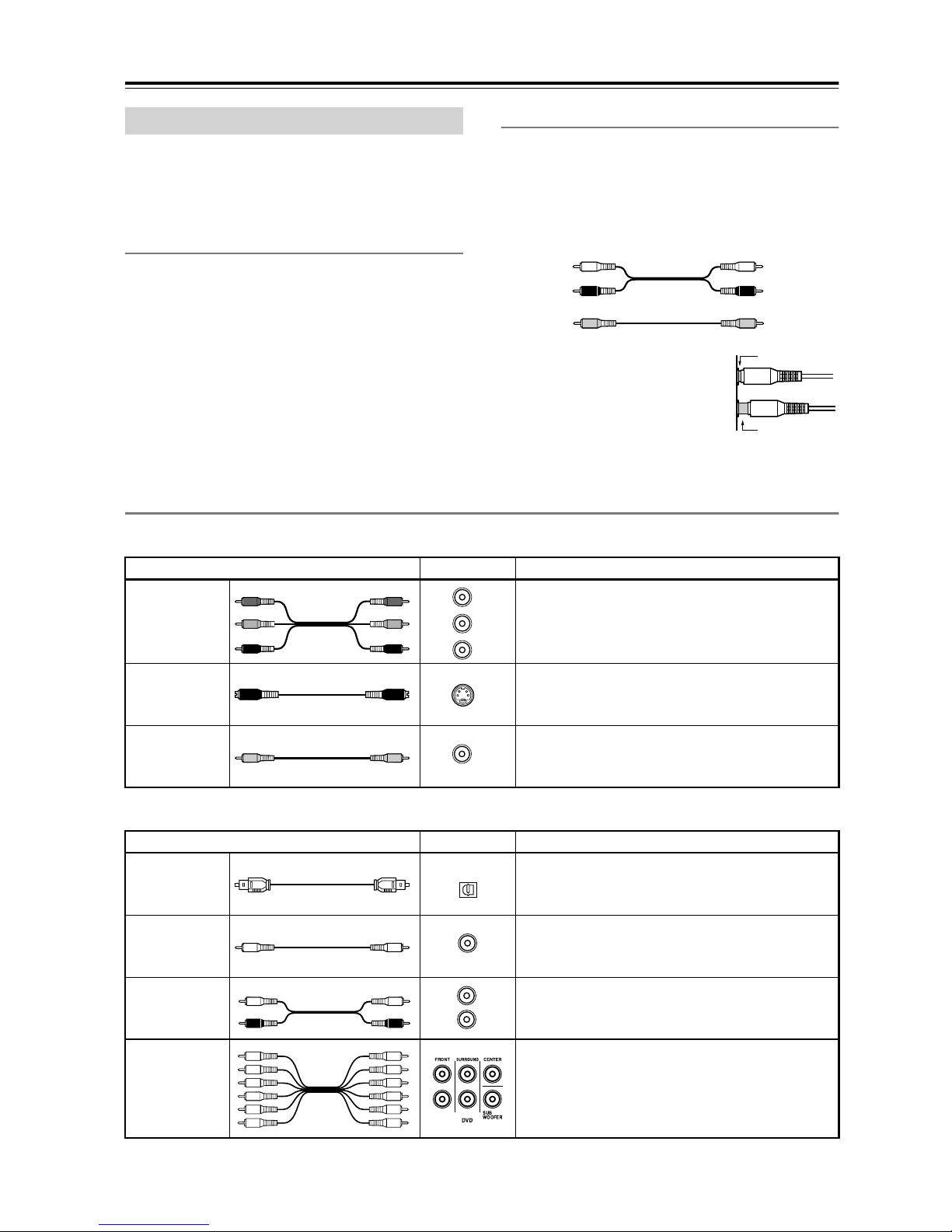
AV Cables & Jacks
Video
Cable Jack Description
Y
Y
P
B
P
B
P
R
PR
Component
video cable
Y
P
B
P
R
AV Connection Color Coding
RCA-type AV connections are usually color coded: red,
white, and yellow. Use red plugs to connect right-channel audio inputs and outputs (typically labeled “R”). Use
white plugs to connect left-channel audio inputs and outputs (typically labeled “L”). And use yellow plugs to
connect composite video inputs and outputs.
Left (white)
Right (red)
(Yellow)
• Push plugs in all the way to make
good connections (loose connections can cause noise or malfunctions).
• To prevent interference, keep
audio and video cables away from
power cords and speaker cables.
Component video separates the luminance (Y) and
color difference signals (P
picture quality. (Some TV manufacturers label their
component video jacks slightly differently.)
Analog audio
Composite video
R, PB), providing the best
Left (white)
Right (red)
(Yellow)
Right!
Wrong!
S-Video cable
Composite
video cable
Audio
Optical digital
audio cable
Coaxial digital
audio cable
Analog audio
cable (RCA)
Multichannel
analog audio
cable (RCA)
S-Video separates the luminance and color signals
S
and provides better picture quality than composite
video.
Composite video is commonly used on TVs, VCRs,
V
and other video equipment. Use only dedicated
composite video cables.
Cable Jack Description
OPTICAL
Offers the best sound quality and allows you to
enjoy surround sound (e.g., Dolby Digital, DTS).
The audio quality is the same as for coaxial.
Offers the best sound quality and allows you to
COAXIAL
L
R
enjoy surround sound (e.g., Dolby Digital, DTS).
The audio quality is the same as for optical.
This cable carries analog audio. It’s the most common connection format for analog audio and can be
found on virtually all AV components.
This cable carries multichannel analog audio and is
typically used to connect DVD players with a 5.1channel analog audio output. Several standard analog audio cables can be used instead of a multichannel cable.
Note: The AV receiver does not support SCART plugs.
22
Page 23
Connecting Your Components—Continued
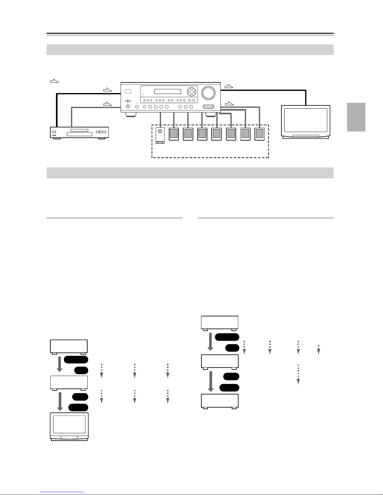
Connecting Both Audio & Video
By connecting both the audio and video outputs of your DVD player and other AV components to the AV receiver, you
can select both the audio and video simultaneously simply by selecting the appropriate input source on the AV receiver.
: Signal Flow
DVD player, etc.
Video
Audio
Speakers (see page 19 for connection
information)
Video
Audio
TV, projector,
etc.
Which Connections Should I Use?
The AV receiver supports several connection formats for compatibility with a wide range of AV equipment. The format
you choose will depend on the formats supported by your other components. Use the following sections as a guide.
For video components, such as a DVD player, you must make two connections—one for audio, one for video.
Video Connection Formats
Video equipment can be connected to the AV receiver
using one of the following video connection formats:
composite video, S-Video, or component video, the latter offering the best picture quality.
When choosing a connection format, bear in mind that
the AV receiver doesn’t convert between formats, so only
outputs of the same format as the input will output the
signal.
For example, if you connect your DVD player to the
S-VIDEO DVD IN, a video signal will be output by the
S-VIDEO MONITOR OUT (for your TV) and the
S-VIDEO VIDEO 1 OUT (for your VCR), but not by
any composite video or component video outputs.
Video Input/Output Diagram
DVD player,
etc.
Output
IN
AV Receiver
OUT
Input
Composite
Composite
Composite
S-Video
S-Video
S-Video
Component
Component
Component
Audio Connection Formats
Audio equipment can be connected to the AV receiver
using the following audio connection formats: analog,
optical, coaxial, and multichannel.
When choosing a connection format, bear in mind that
the AV receiver doesn’t convert between formats.
For example, audio signals connected to an OPTICAL or
COAXIAL digital input are not output by the analog
TAPE OUT, so if you want to record from, for example,
your CD player, in addition to connecting it to a digital
input, you must also connect it to the analog CD IN.
Audio Input/Output Diagram for Recording
CD player,
etc.
Output
IN
AV Receiver
OUT
Input
Cassette
recorder, etc.
Optical
Optical
Coaxial
Coaxial
Analog
Analog
Analog
Multichannel
Multichannel
TV,
projector,
etc.
23
Page 24

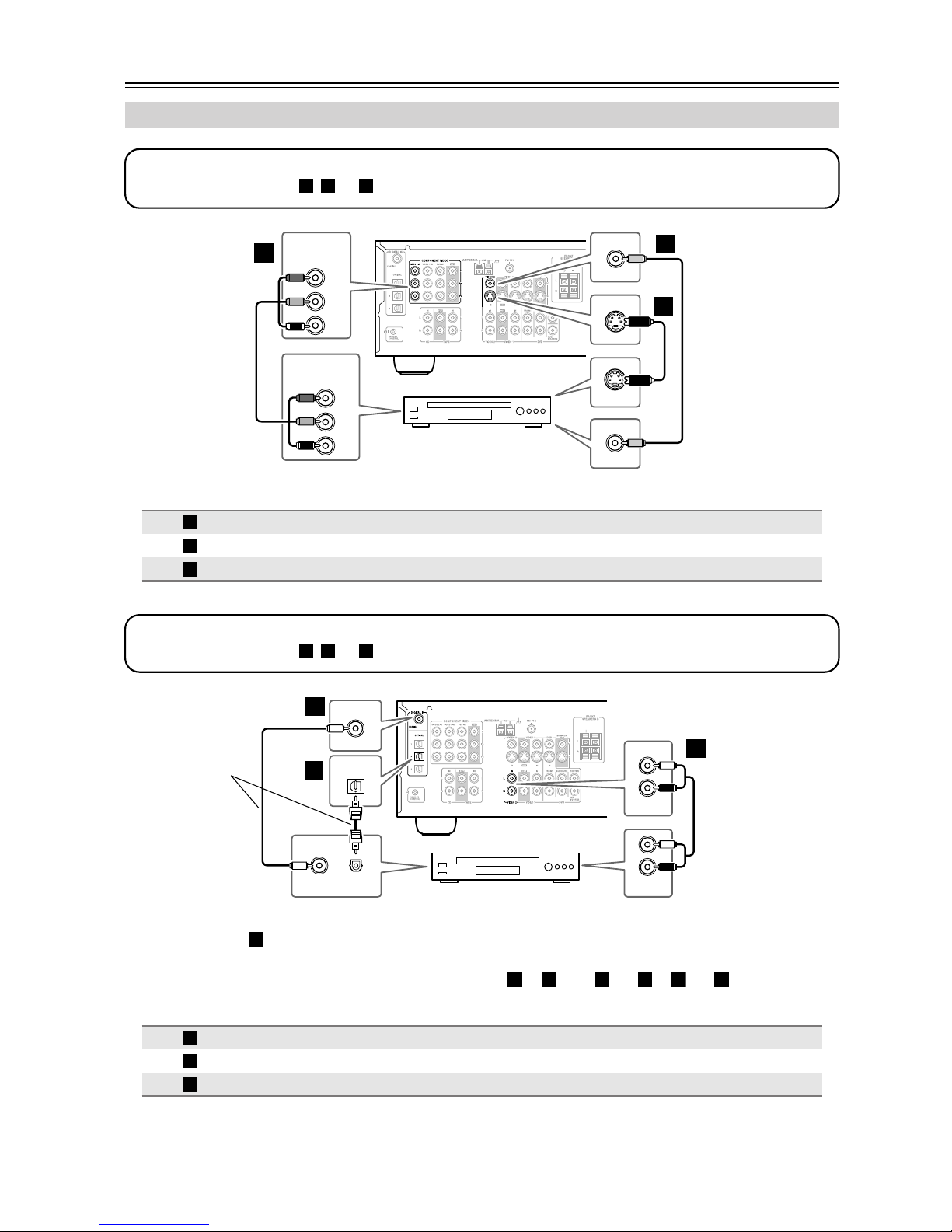
Connecting Your Components—Continued
a
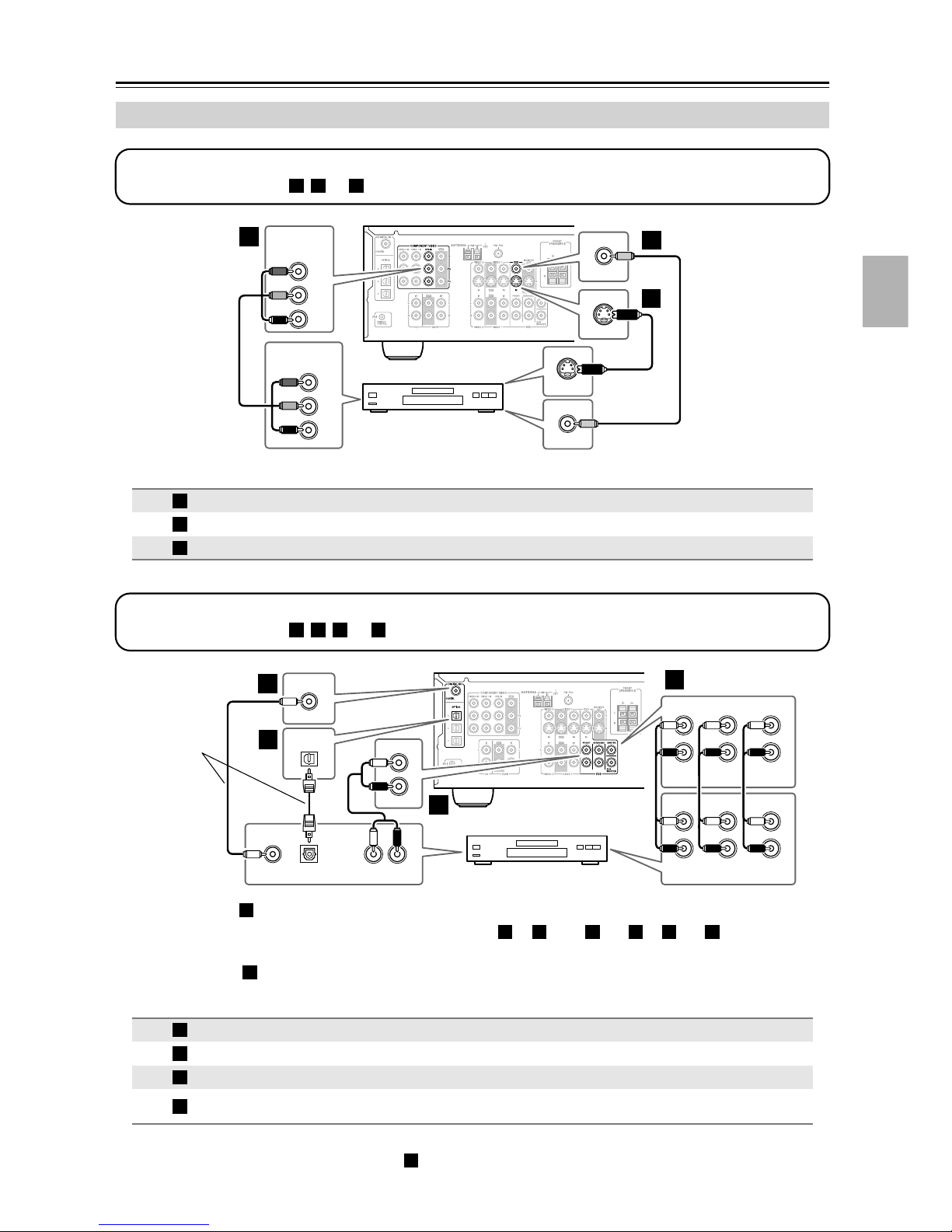
Connecting a TV or Projector
Step 1: Video Connection
Choose a connection type ( , , or ) that matches the TV, and then make the connection.
A B C
A
COMPONENT VIDEO
Y
B
P
PR
COMPONENT VIDEO
IN
Y
P
B
PR
TV, projector,
etc.
S VIDEO IN
VIDEO IN
MONITOR
OUT
MONITOR
OUT
C
V
B
S
Connection HT-R530 Signal flow TV Picture quality
A
B
C
COMPONENT VIDEO OUT
MONITOR OUT S
MONITOR OUT V
⇒
⇒
⇒
Component video input Best
S-Video input Better
Composite video input Standard
Step 2: Audio Connection
Choose a connection type ( , , or ) that matches the TV, and then make the connection.
a b c
DIGITAL IN
Connect one or
the other
• With the basic connection, you can listen to or record audio from the TV, and listen via speaker set B.
a
• To enjoy Dolby and DTS listening modes, use connection or . (Use and or and for recording.)
b
c
COAXIAL
OUT
COAXIAL
OPTICAL
2
OPTICAL
OUT
TV, projector,
etc.
b c a b
L
R
VIDEO 2
L
R
AUDIO
OUT
a
IN
c
Connection HT-R530 Signal flow TV
a
b
c
VIDEO 2 IN L/R
DIGITAL IN COAXIAL
DIGITAL IN OPTICAL 2
⇐
⇐
⇐
Analog audio L/R output
Digital coaxial output
Digital optical output
Hint!
If your TV has no audio outputs, connect your VCR to the AV receiver and use its tuner.
24
Page 25
Connecting Your Components—Continued
b
Connecting a DVD player
Step 1: Video Connection
Choose a connection type ( , , or
A
A B C
COMPONENT VIDEO
DVD IN
Y
P
PR
COMPONENT VIDEO
OUT
Connection HT-R530 Signal flow DVD player Picture quality
A
B
C
COMPONENT VIDEO DVD IN
DVD IN S
DVD IN V
) that matches the DVD player, and then make the connection.
DVD
V
IN
B
Y
B
P
PR
DVD player
⇐
⇐
⇐
S VIDEO OUT
Component video output Best
Composite video output Standard
DVD
S
IN
VIDEO OUT
S-Video output Better
C
The TV must be con-
B
nected to the AV
receiver with the same
type of connection.
Step 2: Audio Connection
Choose a connection type ( , , , or ) that matches your DVD player, and then make the connection.
Connect one
or the other
• With the basic connection, you can listen to or record audio from a DVD, and listen via speaker set B.
a
• To enjoy Dolby and DTS listening modes, use connection or . (Use and or and for recording.)
a b c d
DIGITAL IN
b
COAXIAL
c
OPTICAL
c
1
COAXIAL
OUT
OPTICAL
OUT
FRONT
L
R
DVD
a
LR
AUDIO
OUT
DVD player
d
FRONT
L
R
FRONT
L
R
c a b a c
SURROUND
DVD
SURR
CENTER
SUB
WOOFER
CENTER
SUB
WOOFER
• To enjoy DVD-Audio or SACD playback from a compatible DVD player with an analog multichannel output,
use connection .
Connection HT-R530 Signal flow DVD player
a
b
c
d
d
DVD IN FRONT
DIGITAL IN COAXIAL
DIGITAL IN OPTICAL 1
DVD IN FRONT, SURROUND,
CENTER, and SUBWOOFER
⇐
⇐
⇐
⇐
Analog audio L/R output
Digital coaxial output
Digital optical output
Analog multichannel output
• If your DVD player has main left and right outputs and multichannel left and right outputs, be sure to use the
main left and right outputs for connection .
a
25
Page 26
Connecting Your Components—Continued
a
Connecting a VCR or DVD Recorder for Playback
In addition to video playback, with this hookup example, you can use the VCR’s tuner to listen to the sound of your
favorite TV programs via the AV receiver. This is useful if the TV has no audio outputs.
Step 1: Video Connection
Choose a connection type ( , , or
A B C
TV must be connected to the AV receiver with the same type of connection.
) that matches the VCR/DVD recorder, and then make the connection. The
COMPONENT VIDEO
A
VIDEO 1 IN
Y
B
P
PR
COMPONENT VIDEO
OUT
Y
B
P
PR
VCR,
S VIDEO OUT
VIDEO OUT
VIDEO 1
IN
VIDEO 1
IN
C
V
B
S
DVD recorder
Connection HT-R530 Signal flow VCR/DVD recorder Picture quality
A
B
C
COMPONENT VIDEO VIDEO 1 IN
VIDEO 1 IN S
VIDEO 1 IN V
⇐
⇐
⇐
Component video output Best
S-Video output Better
Composite video output Standard
Step 2: Audio Connection
Choose a connection type ( , , or ), and then make the connection.
a b c
DIGITAL IN
b
Connect one
or the other
• With the basic connection, you can listen to the VCR/DVD recorder, and listen via speaker set B.
a
c
COAXIAL
• To enjoy Dolby and DTS listening modes, use connection or . (Use and or and to listen via
speaker set B.)
Connection HT-R530 Signal flow VCR/DVD recorder
a
b
c
VIDEO 1 IN L/R
DIGITAL IN COAXIAL
DIGITAL IN OPTICAL 2
26
OUT
COAXIAL
OPTICAL
2
OPTICAL
OUT
VCR,
DVD recorder
b c a b
⇐
⇐
⇐
IN
L
R
VIDEO 1
L
R
AUDIO
OUT
Analog audio L/R output
Digital coaxial output
Digital optical output
a
c
Page 27
Connecting Your Components—Continued
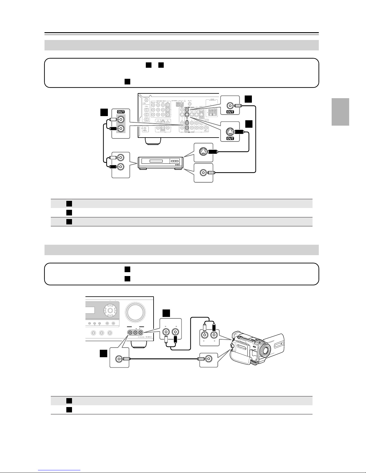
Connecting a VCR or DVD Recorder for Recording
Step 1: Choose a video connection type ( or ) that matches the VCR/DVD recorder, and make the connection.
A B
The video source that you want to record must be connected to the AV receiver with the same type of connection.
Step 2: Make audio connection
.
a
VIDEO 1
B
V
a
L
R
VIDEO 1
AUDIO
IN
L
R
VCR,
DVD recorder
S VIDEO IN
VIDEO IN
Connection HT-R530 Signal flow VCR/DVD recorder Picture quality
A
B
a
VIDEO 1 OUT S
VIDEO 1 OUT V
VIDEO 1 OUT L/R
⇒
⇒
⇒
VIDEO 1
A
S
S-Video input Better
Composite video input Standard
Audio L/R input —
Connecting a Camcorder, Games Console, or Other Device
Step 1: Make video connection .
Step 2: Make audio connection .
TUNING / PRESET
RETURN
DIMMER MEMORY
TUNING MODE
CLEAR
TAPE TUNER CD
A
Connection HT-R530 Signal flow Camcorder/console
A
a
VIDEO 3 INPUT L/R
A
a
MASTER VOLUME
ENTER
SETUP
VIDEO 3 INPUT
VIDEO 3 INPUT
AUDIO
LR
VIDEO
VIDEO 3 INPUT
a
VIDEO 3 INPUT
LR
AUDIO
⇐
⇐
LR
AUDIO
OUT
VIDEO OUT
Camcorder, games console,
etc.
Composite video output
Analog audio L/R output
27
Page 28
Connecting Your Components—Continued
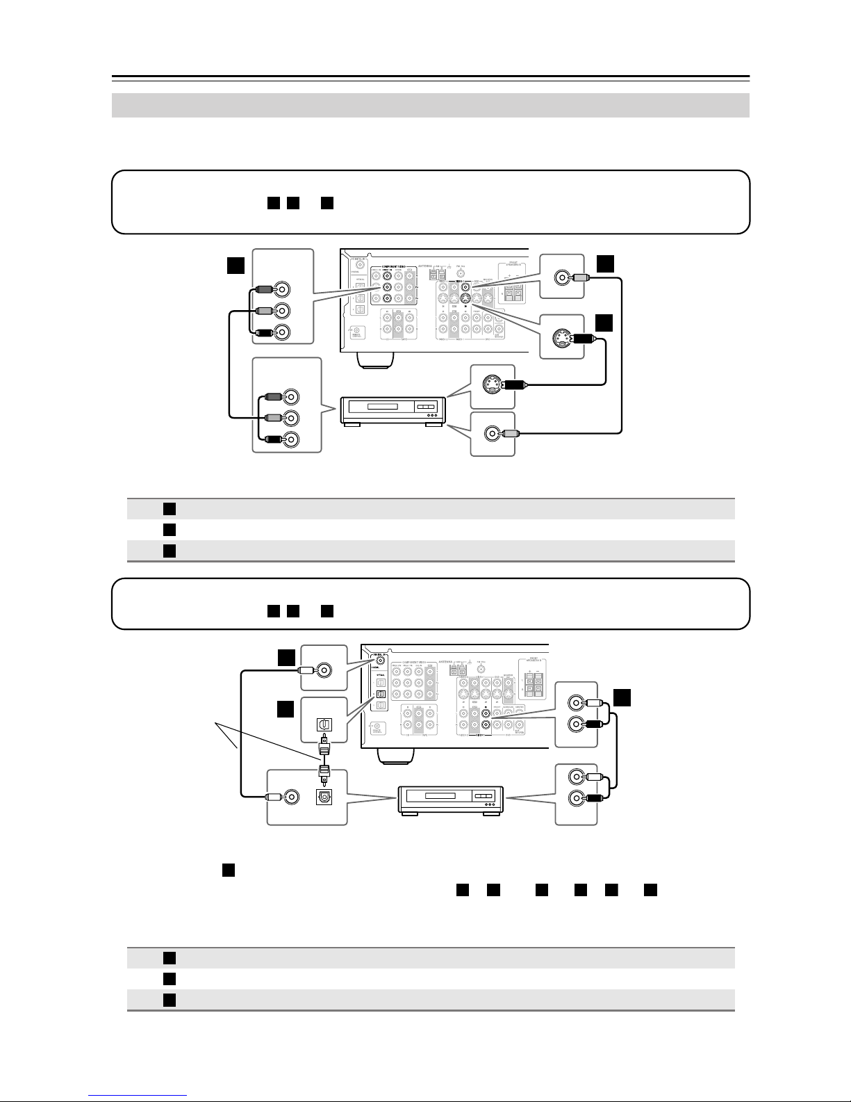
a
Connecting a Satellite, Cable, Set-top box, or Other Video Source
Step 1: Video Connection
Choose a connection type ( , , or
A B C
) that matches the video source, and then make the connection.
COMPONENT VIDEO
A
VIDEO 2 IN
Y
B
P
PR
COMPONENT VIDEO
OUT
Y
P
B
PR
Satellite, cable,
set-top box, etc.
VIDEO 2
V
IN
VIDEO 2
S
IN
S VIDEO OUT
VIDEO OUT
C
The TV must be con-
B
nected to the AV
receiver with the same
type of connection.
Connection HT-R530 Signal flow Video source Picture quality
A
B
C
COMPONENT VIDEO VIDEO 2 IN
VIDEO 2 IN S
VIDEO 2 IN V
⇐
⇐
⇐
Component video output Best
S-Video output Better
Composite video output Standard
Step 2: Audio Connection
Choose a connection type ( , , or ) that matches the video source, and then make the connection.
a b c
b
DIGITAL IN
c
COAXIAL
OUT
COAXIAL
OPTICAL
2
OPTICAL
OUT
Satellite, cable,
IN
L
R
VIDEO 2
L
R
AUDIO
OUT
a
Connect one
or the other
set-top box, etc.
• With the basic connection, you can listen to or record audio from the video source, and listen via speaker
a
set B.
• To enjoy Dolby and DTS listening modes, use connection or . (Use and or and for recording.)
Connection HT-R530 Signal flow Video source
a
b
c
VIDEO 2 IN L/R
DIGITAL IN COAXIAL
DIGITAL IN OPTICAL 2
b c a b
⇐
⇐
⇐
Analog audio L/R output
Digital coaxial output
Digital optical output
c
28
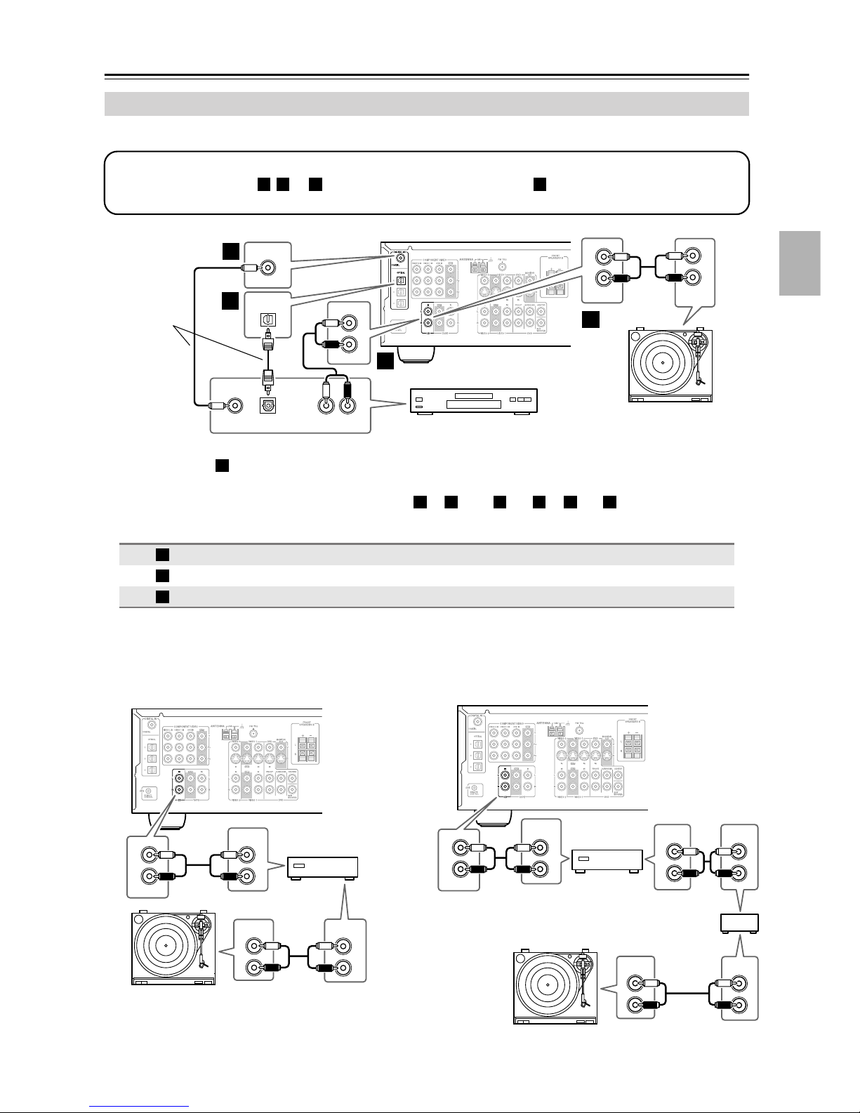
Page 29
Connecting Your Components—Continued
c
Connecting a CD Player or Turntable
■ CD Player, or Turntable with Built-in Phono Preamp
Step 1:
Choose a connection type ( , , or ) that matches the CD player, or choose for a turntable with a built-in phono
preamp, and then make the connection.
a b c a
IN
L
R
CD
AUDIO
OUTPUT
a
Turntable (MM) with
built-in phono
Connect one
or the other
b
c
COAXIAL
OUT
DIGITAL IN
COAXIAL
OPTICAL
1
OPTICAL
OUT
IN
L
R
CD
a
LR
AUDIO
OUT
CD player
preamp
• With the basic connection, you can listen to or record audio from the CD player or turntable, and listen via
a
speaker set B.
• To connect the CD player digitally, use connection or . (Use and or and for recording.)
Connection HT-R530 Signal flow CD or turntable
a
b
c
CD IN L/R
DIGITAL IN COAXIAL
DIGITAL IN OPTICAL 1
■ Turntable with no Phono Preamp Built-in
A phono preamp is necessary to connect a turntable that
doesn’t have a phono preamp built-in.
b
⇐
⇐
⇐
a b a c
Analog audio L/R output
Digital coaxial output
Digital optical output
■ Turntable with an MC (Moving Coil) Cartridge
An MC head amp and phono preamp are necessary to
connect a turntable with an MC (Moving Coil) cartridge.
L
R
AUDIO
IN
L
R
CD
OUTPUT
AUDIO
OUTPUT
L
R
L
R
Phono preamp
AUDIO
INPUT
L
R
AUDIO
IN
L
R
CD
OUTPUT
L
R
Phono
AUDIO
INPUT
L
R
AUDIO
OUTPUT
L
R
preamp
MC head amp or
MC transformer
AUDIO
OUTPUT
L
R
AUDIO
INPUT
L
R
29
Page 30
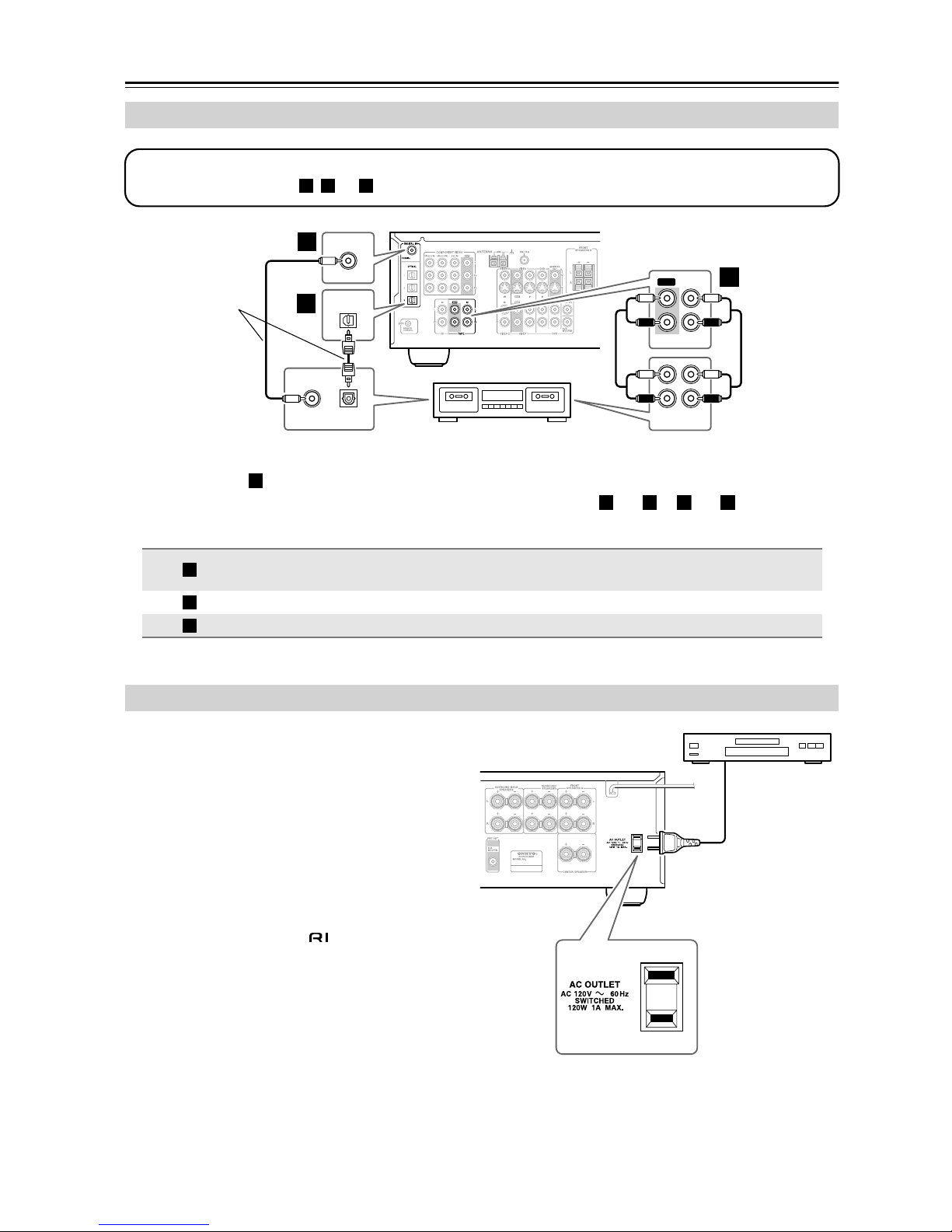
Connecting Your Components—Continued
a
Connecting a Cassette, CDR, MiniDisc, or DAT Recorder
Step 1:
Choose a connection type ( , , or ) that matches the recorder, and then make the connection.
a b c
DIGITAL IN
b
Connect one
or the other
c
COAXIAL
OUT
COAXIAL
OPTICAL
3
OPTICAL
OUT
OUT
TAPE
L
R
IN OUT
REC PLAY
a
IN
L
R
L
R
Cassette recorder, CDR,
etc.
• With the basic connection, you can play and record with the recorder, and listen via speaker set B.
• To connect the recorder digitally for playback purposes, use connections and or and .
a
a b
c
Connection HT-R530 Signal flow Cassette/CDR/MD/DAT recorder
a
b
c
TAPE IN L/R
TAPE OUT L/R
DIGITAL IN COAXIAL
DIGITAL IN OPTICAL 3
⇐
⇒
⇐
⇐
Analog audio L/R output
Analog audio L/R input
Digital coaxial output
Digital optical output
Connecting the Power Cord of Another Component
The AV receiver has an AC outlet on its rear panel for
connecting the power cord of another AV component.
The other component’s power switch can then be left in
the ON position so that it turns on or off when the AV
receiver is set to On or Standby.
Caution:
• Make sure that the capacity of the component that
you connect to the AC OUTLET does not exceed
the stated capacity (e.g., 100 W).
Notes:
• Onkyo components with jacks should be connected directly to wall outlets, not the AV
receiver’s AC OUTLET.
• The socket type and capacity will depend on the
country in which you purchased the AV receiver.
American model
30
Page 31

Connecting Your Components—Continued
Connecting Onkyo Components
Step 1: Be sure that the Onkyo component is connected to the AV receiver with an analog audio cable (RCA).
Step 2: Make the connection.
With (Remote Interactive) you can use the following special functions:
Auto Power On/Standby
When you start playback on a component connected via , if the AV receiver is in Standby, it will turn on and select
that component as the input source automatically. Similarly, when the AV receiver is set to Standby, all components
connected via will also enter Standby. This function will not work if a component’s power cord is connected to the
AV receiver’s AC OUTLET.
Direct Change
When playback is started on a component connected via , the AV receiver automatically selects that component as
the input source. If the DVD player is connected to the AV receiver’s multichannel input, you must press the
[MULTI CH] button (see page 35) to listen to all channels because the Direct Change function selects only the DVD
IN FRONT jacks.
Remote Control
You can control other -compatible Onkyo components by pointing the remote controller at the AV receiver’s remote
control sensor. You must enter the appropriate remote control code first (page 53).
Notes:
• Use only cables for connections.
cables are supplied with Onkyo players (DVD,
L
R
CD, etc.).
• Some components have two jacks, you can
connect either one to the AV receiver. The other is
for connecting additional -compatible compo-
REMOTE
CONTROL
FRONT
nents.
• Connect the AV receiver’s jack to only Onkyo
components. Connecting to other manufacturer’s
components may cause them to malfunction.
• Some components may not support all functions. Refer to the manuals supplied with your
components.
e.g., CD player
e.g., DVD player
ANALOG
AUDIO OUT
ANALOG
AUDIO OUT
LR
LR
Connecting the Power Cord
Notes:
• Before connecting the power cords, connect all of your speakers and AV components.
• Turning on the AV receiver and subwoofer may cause a momentary power surge that might interfere with other
electrical equipment on the same circuit. If this is a problem, plug them into a different branch circuit.
IN
CD
L
R
DVD
31
Page 32

Turning On
STANDBY/ON
STANDBY indicator
STANDBY/ON
STANDBY
A SPEAKERS B
PHONES
PURE AUDIO
+
STEREO
TONE
MULTl CH DVD VIDEO 1 VIDEO 2
VCR
LISTENING MODE
DISPLAY
DIGITAL INPUT
RT/PTY/TP MEMORY
VIDEO 3 TAPE TUNER CD
Turning On the AV Receiver
1
AV receiver
STANDBY/ON
or
Remote
controller
Press the [STANDBY/ON] button.
Alternatively, press the remote controller’s [RECEIVER] button followed
by the [ON] button.
The AV receiver comes on, the display lights up, and the STANDBY indicator goes off.
To turn the AV receiver off, press the [STANDBY/ON] button, or the remote controller’s [STANDBY] button. The AV receiver will enter Standby mode. To prevent any
loud surprises the next time you turn on the AV receiver, always turn down the volume
before turning it off.
CLEAR
TUNING MODE
TUNING / PRESET
ENTER
RETURN
STANDBY
ON
RECEIVER
MASTER VOLUME
SETUP
VIDEO 3 INPUT
VIDEO
AUDIO
LR
ON STANDBY
123
V1V2V
456
789
+
10
--/---
INPUT
GUIDE
TOP MENU
TAPE/AMP
INPUT SELECTOR
MULTI CH
0
10 11 12
DIMMER SLEEP
TV
VOL
RECEIVER
REMOTE MODE
DVD
3
DVD
VCR
CDTAPE TUNER
CLR
CH
VOL
DISC
PREVIOUS
MENU
CD
TV
SAT
CABLE
MD
CDR
To turn on the subwoofer, press its [POWER] switch to the ON position (not North
American models).
Smooth Operation in a Few Easy Steps
To ensure smooth operation, here’s a few easy steps to help you configure the AV receiver before you use it for the
very first time. These settings only need to be made once.
■ Have you connected a component to a digital audio input?
If you have, see “Assigning Digital Inputs to Input Sources” on
page 33.
■ Have you connected an Onkyo MD recorder or CD recorder to the TAPE IN/OUT jacks?
If you have, see “Changing the TAPE/MD/CDR Display” on
page 33.
TESTING THE SPEAKERS
To test that all of the speakers are working properly, press the remote controller’s [TEST TONE] button. The
test tone will be output by each speaker in turn and the name of each speaker will appear on the display. To turn off
the test tone, press the [TEST TONE] button again.
• If the test tone is not produced by a speaker, or it’s produced by a speaker other than that shown on the display,
you may have wired the speakers incorrectly and you should check your connections (see page 19).
COAX
OPT1
OUT IN
TAPE
CD recorder / MD recorder
32
Page 33

First Time Setup
Assigning Digital Inputs to Input
Sources
2, 3
STANDBY/ON
A SPEAKERS B
PHONES
STANDBY
PURE AUDIO
+
STEREO
TONE
MULTl CH DVD VIDEO 1 VIDEO 2
VCR
LISTENING MODE
DISPLAY
DIGITAL INPUT
VIDEO 3 TAPE TUNER CD
RT/PTY/TP MEMORY
TUNING / PRESET
ENTER
RETURN
TUNING MODE
CLEAR
MASTER VOLUME
SETUP
VIDEO 3 INPUT
VIDEO
AUDIO
LR
1
To enjoy Dolby Digital and DTS, you must connect your
DVD player to the AV receiver by using a digital audio
connection (coaxial or optical).
With this function, you can assign digital inputs to input
sources. For example, if you connect your DVD player
to DIGITAL IN OPTICAL 1, you’ll need to assign that
input (OPT1) to the DVD input source.
You can change the assignments as follows.
Note:
Make sure you also set your digital sources to send out a
digital signals. Please refer to the digital sources’ manual.
1
DVD VIDEO 1 VIDEO 2
VCR
VIDEO 3 TAPE TUNER
CD
Press the input selector button
for the source that you want to
assign.
(Digital inputs cannot be assigned to
the TUNER input source.)
Changing the TAPE/MD/CDR Display
If you connect an -compatible Onkyo MiniDisc
recorder or CD recorder to the TAPE IN/OUT jacks, for
to work properly, you must change this setting.
This setting can only be changed on the AV receiver.
STANDBY/ON
A SPEAKERS B
PHONES
STANDBY
PURE AUDIO
+
STEREO
TONE
MULTl CH DVD VIDEO 1 VIDEO 2
VCR
LISTENING MODE
DISPLAY
DIGITAL INPUT
VIDEO 3 TAPE TUNER CD
RT/PTY/TP MEMORY
TUNING / PRESET
RETURN
TUNING MODE
CLEAR
MASTER VOLUME
ENTER
SETUP
VIDEO 3 INPUT
VIDEO
AUDIO
LR
1, 2
1
2
TAPE
TAPE
Press the [TAPE] input selector
button so that “TAPE” appears
on the display.
Press and hold down the [TAPE]
input selector button (about 3
seconds) to set the display.
Repeat this step to select TAPE, MD, or
CDR.
2
DIGITAL INPUT
Press the [DIGITAL INPUT]
button.
The current assignment appears.
3
DIGITAL INPUT
Press the [DIGITAL INPUT] button repeatedly to select COAX,
OPT1, OPT2, OPT3, or “– – – –”
(analog).
By default, the DVD input source is assigned to
[COAX].
33
Page 34

Playing Your AV Components
Basic AV Receiver Operation
VIDEO
4
MASTER VOLUME
VIDEO 3 INPUT
AUDIO
LR
1
2
2
STANDBY/ON
A SPEAKERS B
PHONES
STANDBY
TONE
MULTl CH DVD VIDEO 1 VIDEO 2
PURE AUDIO
MULTI CH
+
DISPLAY
STEREO
LISTENING MODE
VIDEO 3 TAPE TUNER CD
VCR
TUNING / PRESET
ENTER
RETURN
DISPLAY
DIGITAL INPUT
RT/PTY/TP MEMORY
SETUP
TUNING MODE
CLEAR
1
ON STANDBY
TAPE/AMP
INPUT SELECTOR
123
V1V2V
456
MULTI CH
789
+
0
10
10 11 12
--/---
DIMMER SLEEP
TV
VOL
INPUT
GUIDE
TOP MENU
SP A/B
ENTER
REMOTE MODE
RECEIVER
3
DVD
CDTAPE TUNER
CLR
CH
DISC
PREVIOUS
MUTING
DVD
CD
TV
VCR
SAT
CABLE
VOL
MENU
1
MD
CDR
4
Subwoofer’s
rear panel
MIN
OUTPUT LEVEL
MAX
1
AV receiver
DVD VIDEO 1 VIDEO 2
VCR
VIDEO 3 TAPE TUNER
CD
2
AV receiver
A SPEAKERS B
3
Remote
controller
Remote
controller
Use the AV receiver’s input selector buttons to select the input source.
To select the input source with the remote controller, press the
[RECEIVER] button, and then use the INPUT SELECTOR buttons.
On the remote controller, the [V1], [V2], and [V3] buttons select the VIDEO 1,
VIDEO 2, and VIDEO 3 input sources respectively.
Use the SPEAKERS [A] and [B] buttons on the AV receiver or the [SP A/B]
button on the remote controller to select the speaker set that you want to
use.
Pressing the remote controller’s [SP A/B] button cycles through the following settings:
Speaker Set A
→ Speaker Set A&B → Speaker Set B → Off.
The A and B speaker indicators show whether
each speaker set is on or off.
Indicators
Note that when speaker set B is turned on, speaker
set A is reduced to 5.1-channel playback.
Start playback on the source component.
When you select DVD or another video component, on your TV you’ll need to select
the video input that’s connected to the AV receiver’s MONITOR OUT.
4
AV receiver
MASTER VOLUME
Remote
controller
VOL
5
34
To adjust the volume, use the MASTER VOLUME control, or the remote
controller’s [VOL] button.
The volume can be set to MIN, 1 through 79, or MAX. The AV receiver is designed for
home theater enjoyment and has a wide volume range for precise adjustment.
To set the level of the subwoofer, use the OUTPUT LEVEL control.
Because our ears are less sensitive to very low bass sounds, there’s a temptation to set
the level of the subwoofer too high. As a rule of thumb, set the subwoofer level to what
you think is the optimal level, and then back it off slightly.
Select a suitable listening mode and enjoy!
See page 40.
Page 35

Playing Your AV Components—Continued
MULTI CH
DISPLAY
ON STANDBY
123
V1V2V
456
789
+
10
--/---
INPUT
STEREO
AUDIO REPEAT
TEST TONE
DISPLAY
RECEIVER
TAPE/AMP
INPUT SELECTOR
MULTI CH
0
10 11 12
DIMMER SLEEP
TV
VOL
LISTENING MODE
SURROUND
RANDOM
SUBTITLE
CH SEL
LEVEL
PLAY MODE
L NIGHT
OR-EQ
-
RC
608M
REMOTE MODE
DVD
3
DVD
VCR
CDTAPE TUNER
SAT
CLR
CH
VOL
DISC
-
LEVEL
DVDHDD
CINE FLTR
CD
TV
CABLE
MD
CDR
RECEIVER
You can display various information about the current
input source as follows.
The following information can typically be displayed for
input sources.
+
Displaying Source Information
Press the [RECEIVER] button,
and then press the [DISPLAY]
button repeatedly to cycle
through the available information.
Input source &
volume
Signal format*
or sampling
frequency
Input source &
listening mode
Using the Multichannel Input
The multichannel input is for connecting a component
with individual 5.1-channel analog audio output jacks,
such as a DVD player or MPEG decoder. See page 25 for
hookup information.
Press the [RECEIVER] button followed by the [MULTI CH] button
so that MULTI CH indicator
appears on the display.
Audio from the multichannel input will
now be used for the DVD input source.
MULTI CH indicator
Note:
• While the multichannel input is selected, the Speaker
Configuration settings on page 48 are ignored, and
signals from the multichannel input are fed to the front
left, front right, center, surround left, and surround
right speakers and subwoofer regardless of those settings.
*If the input signal is analog, no format information is
displayed. If the input signal is PCM, the sampling frequency is displayed. If the input signal is digital but not
PCM, the signal format is displayed. Information is displayed for about three seconds, then the previously displayed information reappears.
Interpreting Surround Channel Information
ABC
A: The number of front channels (front left, front right,
and center).
B: The number of surround channels (surround left and
surround right). If there’s surround back channel
information, this number will be 3.
C: LFE channel for subwoofer (1 means yes).
35
Page 36

Using the Tuner
Listening to the Radio
TUNING MODE
TUNING
RT/PTY/TP MEMORY
TUNING / PRESET
ENTER
RETURN
TUNING MODE
CLEAR
STANDBY/ON
A SPEAKERS B
PHONES
STANDBY
PURE AUDIO
+
STEREO
TONE
MULTl CH DVD VIDEO 1 VIDEO 2
VCR
LISTENING MODE
DISPLAY
DIGITAL INPUT
VIDEO 3 TAPE TUNER CD
TUNER
With the built-in tuner, you can enjoy AM and FM radio
stations. You can store your favorite stations as presets
for quick selection.
1
TUNER
Use the [TUNER] input selector
button to select either AM or FM.
In this example, FM has been selected.
Band Frequency
(Actual display depends on country.)
MASTER VOLUME
SETUP
VIDEO 3 INPUT
VIDEO
AUDIO
LR
Tuning into Radio Stations
■ Auto Tuning Mode
1
TUNING MODE
2
TUNING / PRESET
ENTER
When tuned into a station, the TUNED indicator
appears. When tuned into a stereo FM station, the FM
STEREO indicator appears on the display, as shown.
Press the [TUNING MODE] button
so that the AUTO indicator
appears on the display.
Press the TUNING Up or Down
[ ]/[ ] button.
Searching stops when a station is
found.
AUTOTUNED
FM STEREO
AM Frequency Step Setup
(not North American model)
Here you can specify the AM frequency step used in
your area. When this setting is changed, all radio presets
are deleted.
1
2
3
Press the [SETUP] button and
use the Up and Down [ ]/[ ]
buttons to select “0. Hardware
Setup,” and then press [ENTER].
Use the Up and Down [ ]/[ ]
buttons to select “AM Freq,” and
then use the Left and Right
[ ]/[ ] buttons to select:
10 kHz: Select if 10 kHz steps are
used in your area.
9 kHz: Select if 9 kHz steps are used
in your area.
Press the [SETUP] button.
Setup closes.
■ Manual Tuning Mode
1
TUNING MODE
Press the [TUNING MODE] button
so that the AUTO indicator disappears from the display.
2
TUNING / PRESET
ENTER
Press and hold the TUNING Up or
Down [ ]/[ ] button.
The frequency stops changing when
you release the button.
Press the buttons repeatedly to change
the frequency one step at a time.
The American model changes FM frequency in 0.2 MHz
steps, 10 kHz steps for AM. For other models it’s
0.05 MHz steps for FM and 9 kHz steps for AM.
In Manual Tuning mode, FM stations will be in mono.
Tuning into weak FM stereo stations
If the signal from a stereo FM station is weak, it may be
impossible to get good reception. In this case, switch to
Manual Tuning mode and listen to the station in mono.
Note:
• This procedure can also be performed on the remote
controller by using its [SETUP] button, arrow buttons,
and [ENTER] button.
36
Page 37

Using the Tuner—Continued
Presetting Radio Stations
2, 4
STANDBY/ON
STANDBY
A SPEAKERS B
PHONES
PURE AUDIO
You can store up to 30 of your favorite radio stations as
presets.
1
2
MEMORY
3
TUNING / PRESET
ENTER
4
MEMORY
+
STEREO
TONE
MULTl CH DVD VIDEO 1 VIDEO 2
LISTENING MODE
VIDEO 3 TAPE TUNER CD
VCR
DISPLAY
DIGITAL INPUT
Tune into the station that you
want to store as a preset.
Press the [MEMORY] button.
The MEMORY indicator appears and
the preset number flashes.
While the MEMORY indicator is
displayed (about 8 seconds), use
the PRESET [ ]/[ ] buttons to
select a preset from 1 through 30.
In this example, preset #3 is selected.
Press the [MEMORY] button
again to store the station.
The station is stored and the preset
number stops flashing.
Repeat this procedure for all your
favorite radio stations.
RT/PTY/TP MEMORY
3
TUNING / PRESET
ENTER
RETURN
TUNING MODE
CLEAR
MASTER VOLUME
SETUP
VIDEO 3 INPUT
VIDEO
AUDIO
LR
Deleting Presets
2
STANDBY/ON
STANDBY
1
A SPEAKERS B
PHONES
PURE AUDIO
+
STEREO
TONE
MULTl CH DVD VIDEO 1 VIDEO 2
LISTENING MODE
VIDEO 3 TAPE TUNER CD
VCR
DISPLAY
DIGITAL INPUT
RT/PTY/TP MEMORY
TUNING MODE
CLEAR
Select the preset that you want to
delete.
See the previous section.
2
MEMORY
TUNING MODE
CLEAR
While holding down the [MEMORY] button, press the
[TUNING MODE] button.
The selected preset is deleted and its
number disappears from the display.
Displaying Radio Information
1
STANDBY/ON
STANDBY
1
A SPEAKERS B
PHONES
DISPLAY
PURE AUDIO
+
STEREO
TONE
MULTl CH DVD VIDEO 1 VIDEO 2
LISTENING MODE
VIDEO 3 TAPE TUNER CD
VCR
DISPLAY
DIGITAL INPUT
RT/PTY/TP MEMORY
TUNING MODE
CLEAR
Press the [DISPLAY] button
repeatedly to cycle through the
available information.
TUNING / PRESET
RETURN
TUNING / PRESET
RETURN
MASTER VOLUME
ENTER
SETUP
VIDEO 3 INPUT
VIDEO
AUDIO
LR
MASTER VOLUME
ENTER
SETUP
VIDEO 3 INPUT
VIDEO
AUDIO
LR
Selecting Preset Stations
STANDBY/ON
STANDBY
A SPEAKERS B
PHONES
PURE AUDIO
TUNING / PRESET
1
ENTER
+
STEREO
TONE
MULTl CH DVD VIDEO 1 VIDEO 2
LISTENING MODE
VIDEO 3 TAPE TUNER CD
VCR
DISPLAY
DIGITAL INPUT
RT/PTY/TP MEMORY
CLEAR
Use the PRESET [ ]/[ ] buttons, or the remote controller’s
CH [+/–] button to select a preset.
TUNING MODE
TUNING / PRESET
RETURN
Band, preset # &
frequency
1
MASTER VOLUME
ENTER
SETUP
VIDEO 3 INPUT
VIDEO
AUDIO
LR
Listening mode
37
Page 38

Common Functions
This chapter explains functions that can be used with any
input source.
DIMMER
CH SEL
OR-EQ
ON STANDBY
123
V1V2V
456
789
+
10
--/---
INPUT
GUIDE
TOP MENU
SP A/ B
STEREO
AUDIO REPEAT
TEST TONE
DISPLAY
RECEIVER
TAPE/AMP
INPUT SELECTOR
MULTI CH
0
10 11 12
DIMMER SLEEP
TV
VOL
ENTER
LISTENING MODE
SURROUND
RANDOM
SUBTITLE
CH SEL
LEVEL
PLAY MODE
L NIGHT
OR-EQ
-
RC
608M
REMOTE MODE
DVD
3
DVD
VCR
CDTAPE TUNER
SAT
CLR
CH
VOL
DISC
PREVIOUS
MENU
MUTING
SETUPRETURN
-
LEVEL
DVDHDD
CINE FLTR
CD
TV
CABLE
MD
CDR
+
Press
[RECEIVER]
first
SLEEP
MUTING
LEVEL – +
Adjusting the Bass & Treble
You can adjust the bass or treble for the front speakers
except when the Direct or Pure Audio (not North American model) listening mode is selected.
1
TONE
Press the AV receiver’s [TONE]
button repeatedly to select either
Bass or Treble.
2
Use the TONE [–]/[+] buttons to
+
adjust.
■ Bass
You can boost or cut low-frequency sounds output by the
front speakers from –10 dB to +10 dB in 2 dB steps.
■ Treble
You can boost or cut high-frequency sounds output by
the front speakers from –10 dB to +10 dB in 2 dB steps.
Muting the AV Receiver
With this function, you can temporarily mute the output
of the AV receiver.
TONE, –, +
STANDBY/ON
A SPEAKERS B
PHONES
STANDBY
TONE
MULTl CH DVD VIDEO 1 VIDEO 2
+
STEREO
VCR
LISTENING MODE
DISPLAY
DIGITAL INPUT
VIDEO 3 TAPE TUNER CD
DIMMER MEMORY
TUNING / PRESET
ENTER
RETURN
TUNING MODE
CLEAR
MASTER VOLUME
SETUP
VIDEO 3 INPUT
VIDEO
AUDIO
LR
PHONES DIMMER
Setting the Display Brightness
With this function, you can adjust the brightness of the
display.
AV receiver
DIMMER
Remote
controller
Press the [DIMMER] button
repeatedly to select: dim, dimmer, or normal brightness.
Press the remote controller’s
[MUTING] button.
The output is muted and the MUTING
indicator flashes on the display, as
shown.
To unmute the AV receiver, press the remote controller’s [MUTING] button again, or adjust the volume. The
output is unmuted and the MUTING indicator goes off.
Muting is cancelled when the AV receiver is set to
Standby.
Using the OptiResponse Equalizer
When using the HT-R530 with the speakers included in
this Package, by turning on the OptiResponse equalizer,
you can enjoy a powerful sound with movies or music.
OR-EQ
Press the remote controller’s
[OR-EQ] button to turn the OptiResponse equalizer on or off.
38
Page 39

Common Functions—Continued
Using the Sleep Timer
With the sleep timer, you can set the AV receiver so that
it automatically turns off after a set period.
Press the remote controller’s
[SLEEP] button repeatedly to
select the required sleep time.
You can set the sleep time from 90 to 10
minutes in 10 minute steps.
The SLEEP indicator appears on the
display when the sleep timer has been
set, as shown. The specified sleep time
appears on the display for about five
seconds, then the previous display
reappears.
SLEEP indicator
To cancel the sleep timer, press the [SLEEP] button
repeatedly until the SLEEP indicator disappears.
To check the remaining sleep time, press the [SLEEP]
button. Note that if you press the [SLEEP] button while
the sleep time is being displayed, you’ll shorten the sleep
time by 10 minutes.
Using Headphones
You can connect a pair of stereo headphones (1/4-inch
phone plug) to the AV receiver’s PHONES jack for private listening, as shown.
STANDBY/ON
A SPEAKERS B
PHONES
PURE AUDIO
Adjusting Speaker Levels
You can adjust the level of each speaker in speaker set A
while listening to an input source. These temporary
adjustments are cancelled when the AV receiver is set to
Standby.
1
Notes:
• You cannot use this function while the AV receiver is
muted.
• Speakers that are set to No or None in the Speaker
Configuration cannot be adjusted.
■ Speaker Set B
While speaker set B is on, you can also adjust the levels
of the left and right speakers in speaker set B, from
–12 dB to +12 dB.
• These settings are stored when the AV receiver is set
to Standby.
• While speaker set B is on, you cannot adjust the levels
of speaker set A’s surround back speakers.
■ Headphones
While a pair of headphones is connected, you can adjust
the volume of the left and right channels individually,
from –12 dB to +12 dB each.
Use the remote controller’s
[CH SEL] button to select each
speaker, and use the [LEVEL–]
and [LEVEL+] buttons to adjust
the volume.
You can adjust the volume of each
speaker from –12 dB to +12 dB
(–15 dB to +12 dB for the subwoofer).
Notes:
• Always turn down the volume before connecting your
headphones.
• Speaker sets A and B are turned off while the headphones plug is inserted in the PHONES jack.
• When you connect a pair of headphones, the listening
mode is set to Stereo, unless it’s already set to Pure
Audio, Mono, Stereo, or Direct.
• When the multichannel DVD input is selected, only
the front left and front right channels can be heard in
the headphones.
• These settings are stored when the AV receiver is set
to Standby.
■ Multichannel DVD Input
While the multichannel DVD input is selected, you can
adjust the level of each 5.1 channel input individually,
from –12 dB to +12 dB. (–30 to +12 dB for the subwoofer.)
• These settings are stored when the AV receiver is set
to Standby.
• Individual speaker levels can also be adjusted in
“3. MultiLevel Setup” (see page 47).
39
Page 40

Using the Listening Modes
Selecting Listening Modes
See “About the Listening Modes” on page 42 for
detailed information about the listening modes.
• The Dolby Digital and DTS listening modes
can only be selected if your DVD player is
connected to the AV receiver with a digital
audio connection (coaxial or optical).
• Listening mode availability depends on the
format of the current input signal.
• While a pair of headphones is connected,
you can select only the Pure Audio (not
North American model), Mono, Direct, or
Stereo listening mode.
Selecting on the AV receiver
RT/PTY/TP MEMORY
TUNING / PRESET
RETURN
TUNING MODE
CLEAR
STANDBY/ON
A SPEAKERS B
PHONES
STANDBY
PURE AUDIO
+
STEREO
TONE
MULTl CH DVD VIDEO 1 VIDEO 2
VCR
LISTENING MODE
DISPLAY
DIGITAL INPUT
VIDEO 3 TAPE TUNER CD
PURE AUDIO
STEREO
LISTENING MODE
■ [PURE AUDIO] button (not North American
model)
This button selects the Pure Audio listening mode.
When this mode is selected, the AV receiver outputs
no video signals and its display is turned off.
MASTER VOLUME
ENTER
SETUP
VIDEO 3 INPUT
VIDEO
AUDIO
LR
Selecting with the Remote Controller
CH
TV
VOL
INPUT
GUIDE
TOP MENU
SP A/ B
SURROUND
LISTENING MODE
SURROUND
STEREO
STEREO
SUBTITLE
AUDIO REPEAT
TEST TONE
CH SEL
PLAY MODE
DISPLAY
OR-EQ
RC
■ [STEREO] button
This button selects the Stereo listening mode.
■ [SURROUND] button
This button selects the Dolby Digital and DTS listening modes.
■ LISTENING MODE [ ]/[ ] buttons
Pressing these buttons repeatedly cycles through all
of the listening modes that can be used with the current input source.
ENTER
-
RANDOM
LEVEL
L NIGHT
608M
VOL
DISC
PREVIOUS
MENU
MUTING
SETUPRETURN
+
-
LEVEL
DVDHDD
CINE FLTR
,
■ [STEREO] button
This button selects the Stereo listening mode.
■ LISTENING MODE [ ]/[ ] buttons
Pressing these buttons repeatedly cycles through all
of the listening modes that can be used with the current input source.
40
Page 41

Using the Listening Modes—Continued
The following table lists all the listening modes and shows which modes can be selected for each input signal format.
*2
DTS-ES
Discrete Matrix
*5
✔
✔
✔
Multich
✔
Input signal format
Source
Listening mode
Pure Audio (not North
American model)
Direct
Stereo
Mono
Multich
PLIIx Movie/Music/Game
Neo:6 Cinema
Neo:6 Music
Dolby D
Dolby D EX
Dolby D+PLIIx Music
Dolby
Dolby D+PLIIx Movie
DTS, DTS 96/24
DTS-ES Discrete
DTS-ES Matrix
DTS
DTS+Neo:6
DTS+Dolby EX
DTS+PLIIx Music
DTS+PLIIx Movie
Onkyo
Original
DSP
*4
Mono Movie
Orchestra
Unplugged
Studio-Mix
TV Logic
All Ch Stereo
Full Mono
CD, TV, VHS,
*3
*4
Analog,
*1
PCM
MD,
turntable,
radio,
cassette,
DTV, etc.
*/2
Dolby D
2/0
(Stereo)
DVD, DTV, etc. DVD, CD, etc. DVD
1/0,1+1 Other 3/2.1
✔ ✔✔✔✔✔✔ ✔ ✔
✔ ✔✔✔✔✔✔ ✔
✔✔ ✔
✔✔
✔
✔
✔ ✔✔✔✔✔✔ ✔
DTS/DTS 96/24
2/0
(Stereo)
✔
✔
✔
*1. In the Pure Audio and Direct listening modes, PCM signals at 32 kHz, 44.1 kHz, and 48 kHz are processed at 64 kHz, 88.2 kHz,
and 96 kHz respectively. 96 kHz signals are processed at 48 kHz for all listening modes other than Pure Audio, Direct, and Stereo.
*2. In the Pure Audio, Direct, Stereo, and DTS 96/24 listening modes, signals are processed as DTS 96/24. Everything else is pro-
cessed as DTS.
*3. If the Surr Back parameter is set to “None,” or speaker set B is on, PLII is used.
*4. Available only when Surround speakers are connected.
*5. If the Surr Back setting is set to “None,” or speaker set B is on, DTS is used.
: Not available when the Surr Back parameter is set to None, or when speaker set B is on.
: Not available when the Surr Back parameter is set to None or 1ch, or when speaker set B is on.
Tip: You can check the format of the digital input signal on page 35, “Displaying Source Information.”
41
Page 42

Using the Listening Modes—Continued
About the Listening Modes
With its built-in surround-sound decoders and DSP programs, the AV receiver can transform your home listening room into a movie theater or concert hall.
The AV receiver’s surround indicators show which
speakers are active in each listening mode.
Front left Center Front right
Subwoofer
left
Surround
back left/
Surround
Direct
The selected input source is output directly with minimal
processing for a pure sound.
Pure Audio (not North American model)
As an extension of Direct mode, this mode turns off the
display, turns off the power to the video circuitry, and
minimizes any other possible noise sources, providing a
high fidelity sound that’s true to the original. (Since the
power to the video circuitry is turned off, no video signals are output while this mode is selected.)
Stereo
The selected input source is processed as a stereo signal
and output by the front left and right speakers and the
subwoofer.
Mono
Use this mode when watching an old movie with a mono
soundtrack, or to select multilingual soundtracks
recorded in the left and right channels of some movies.
It can also be used when playing a DVD or other source
with multiplexed audio, such as a karaoke DVD.
Dolby Pro Logic II Movie
Use this mode with DVDs and videos that bear the Dolby Surround
logo or TV shows that feature Dolby Surround. You can
also use this mode with stereo movies or TV shows and
the AV receiver will create a 5.1 surround mix from the
2-channel stereo.
Dolby Pro Logic II Music
Use this mode to add 5.1 surround to stereo sources such
as music CDs and DVDs.
right
Surround
right
Dolby Pro Logic IIx
If you’ve connected surround back speakers to the AV
receiver, Dolby Pro Logic IIx allows you to enjoy 7.1channel playback from 2-channel or 5.1-channel music
or movies. Dolby Pro Logic IIx provides a well defined,
natural multichannel surround-sound experience, putting the listener in a seamless envelope of sound. The
added drama and natural sound enhance the listening
experience with CDs, movies, and games.
Dolby Pro Logic IIx has three modes of operation:
Movie mode for movies, Music mode for listening to
music, and Game mode for use with games consoles
with 2-channel stereo outputs.
Dolby Digital
With this format you can experience the
same superb sound that you get at a movie
theater or concert hall. Use this mode with DVDs that
bear the Dolby Digital logo.
Dolby Digital EX
With an added surround-back channel,
this 6.1 channel format offers a heightened
sense of space, for added realism with moving sounds,
such as those that rotate 360 degrees or pass overhead.
Dolby Digital EX material can also be played on conventional 5.1 channel systems, in which case the surroundback channel audio is split between the surround left and
right channels. Use this mode with DVDs that have a
5.1-channel soundtrack and bear the Dolby Digital logo.
DTS
This digital surround format offers a surround sound experience with exceptional
fidelity. It uses compressed digital audio
data, with six discrete channels (5.1), and the
ability to handle large amounts of audio data while
remaining faithful to the original. DTS provides very
high-quality sound. You’ll need a DTS compatible DVD
player in order to enjoy DTS material. Use this mode
with DVDs and CDs that bear the DTS logo.
DTS 96/24
This mode provides higher audio quality.
Use it with CDs and DVDs that bear the
DTS 96/24 logo.
DTS-ES Discrete
This is DTS with an added surround back
channel for 6.1 surround sound. Use it with
program material recorded in DTS 6.1 format. With the
additional surround back channel, this format offers 6.1
fully independent digital channels, providing a realistic
sense of movement and space. Use it with program material recorded in DTS 6.1, such as CDs and DVDs that
bear the DTS-ES logo.
42
Page 43

Using the Listening Modes—Continued
DTS-ES Matrix
This is DTS with an added surround back
channel for 6.1 surround sound. Use it to
provide 6.1 channel surround playback
with program material recorded in DTS 5.1
format. Since DTS 5.1 program material
contains surround back channel information, all channels can be reconstructed for 6.1-channel
playback. Use this mode with CDs and DVDs that bear
the DTS-ES or DTS logo.
Neo:6
This mode provides 6.1-channel playback from 2-channel sources. It offers six full-bandwidth channels with
excellent separation. There are two modes of operation:
Cinema mode for movies, and Music mode for listening
to music.
Cinema mode simulates the realistic sense of movement
that you get with 6.1-channel surround sound sources.
Use this mode with videos, DVDs, and TV shows that
feature stereo sound.
Music mode uses the surround channels to simulate a
natural sound field that cannot be produced with conventional stereo. Use this mode with stereo material such as
music CDs.
Onkyo Original DSP Modes
Mono Movie
This mode is suitable for use with old movies and other
mono sound sources. The center speaker outputs the
sound as it is, while reverb is applied to the sound output
by the other speakers, giving presence to even mono
material.
Orchestra
Suitable for classical or operatic music. The surround
channels are emphasized in order to widen the stereo
image. In addition, it simulates the natural reverberation
of a large hall.
Unplugged
Suitable for acoustic instrument sounds, vocals, and jazz
music. By emphasizing the front stereo image, it simulates the stage-front experience.
Studio-Mix
Suitable for rock and pop music. Listening to music in
this mode creates a lively sound field with a powerful
acoustic image, like being at a club or rock concert.
TV Logic
Adds realistic acoustics to TV shows produced in a TV
studio. In addition, it adds surround effects to the entire
sound and adds clarity to voices.
All Ch Stereo
Ideal for background music. The front, surround, and
surround back channels create a stereo image that fills
the entire listening area.
Full Mono
In this mode, all speakers output mono audio, so the
music sounds the same regardless of where you are.
43
Page 44

Adjusting the Listening Modes
Using the CinemaFILTER
ENTER
ON STANDBY
123
V1V2V
456
789
+
10
--/---
INPUT
GUIDE
TOP MENU
SP A/ B
STEREO
AUDIO REPEAT
TEST TONE
DISPLAY
TAPE/AMP
INPUT SELECTOR
MULTI CH
0
10 11 12
DIMMER SLEEP
TV
VOL
ENTER
LISTENING MODE
SURROUND
SUBTITLE
RANDOM
CH SEL
PLAY MODE
OR-EQ
-
RC
608M
REMOTE MODE
DVD
RECEIVER
3
DVD
VCR
CDTAPE TUNER
SAT
CLR
CH
VOL
DISC
PREVIOUS
MENU
MUTING
SETUPRETURN
-
LEVEL
LEVEL
DVDHDD
CINE FLTR
L NIGHT
CD
TV
CABLE
RECEIVER
MD
CDR
With the CinemaFILTER, you can soften overly bright
movie soundtracks, which are typically mixed for reproduction in a movie theater.
CinemaFILTER can be used with the following listening
modes: Dolby Digital, Dolby Digital EX, Dolby Pro
Logic II Movie, Dolby Pro Logic IIx Movie, DTS,
DTS-ES, DTS Neo:6 Cinema, DTS 96/24, DTS+Neo:6,
and DTS+Dolby EX.
1
SETUP
+
CINE FLTR
L NIGHT
Using the Audio Adjust Functions
These functions only work with speaker set A.
Audio Adjust provides various functions for adjusting
the sound.
Press the [RECEIVER] button,
and then press the [CINE FLTR]
button repeatedly to select:
On: CinemaFILTER on.
Off: CinemaFILTER off.
Using the Late Night Function
(Dolby Digital only)
With the Late Night function, you can reduce the
dynamic range of Dolby Digital material so that you can
still hear quiet parts even when listening at low volume
levels—ideal for watching movies late at night when you
don’t want to disturb anyone.
1
Notes:
• The effect of the Late Night function depends on the
Dolby Digital material that you are playing, and with
some material there will be little or no effect.
• The Late Night function is set to Off when the AV
receiver is set to Standby.
Press the [RECEIVER] button,
and then press the [L NIGHT] button repeatedly to select:
Off: Late Night function off.
Low: Small reduction in dynamic
range.
High: Big reduction in dynamic
range.
1
2
Press the [RECEIVER] button followed by the [SETUP] button.
Use the Up and Down [ ]/[ ]
buttons to select “4. Audio
Adjust,” and then press the
[ENTER] button.
44
Page 45

Adjusting the Listening Modes—Continued
3
4
5
The Audio Adjust functions are explained below.
Use the Left and Right [ ]/[ ]
buttons to change the settings.
Press the Down [ ] button to
select the next setting.
Repeat step 3 to complete all settings.
Press the [SETUP] button.
Setup closes.
Input Channel Settings
■ Multiplex
This setting determines which channel is output from a
stereo multiplex source. Use it to select audio channels
or languages with multiplex sources, multilingual TV
broadcasts, and so on.
Main: The main channel is output (default).
Sub: The sub channel is output.
M/S: Both the main and sub channels are output.
■ Mono (2ch)
This setting determines which channel is output when
the Mono listening mode is used with a stereo source.
L+R: Both the left and right channels are output
(default).
L: Only the left channel is output.
R: Only the right channel is output.
PL II & PL IIx Music Mode Settings
These settings apply to only 2-channel (stereo) sources.
■ Panorama
With this function, you can broaden the width of the
front stereo image when using the Pro Logic II Music or
Pro Logic IIx Music listening mode.
On: Panorama function on.
Off: Panorama function off (default).
If the stereo image feels too wide, or there’s too much
surround sound, move the sound field forward to
improve the balance. Conversely, if the stereo image
feels like it’s in mono, or there’s not enough surround
sound, move it backward.
■ Center Width
With this function, you can adjust the width of the sound
from the center speaker when using the Pro Logic II
Music or Pro Logic IIx Music listening mode. Normally
if you’re using a center speaker, the center channel sound
is output by only the center speaker. (If you’re not using
a center speaker, the center channel sound will be distributed to the front left and right speakers to create a phantom center). This setting controls the front left, right, and
center mix, allowing you to adjust the weight of the center channel sound. It can be adjusted from 0 to 7 (default
is 3).
DTS Neo:6 Music Mode Setting
■ Center Image
The DTS Neo:6 Music listening mode creates 6-channel
surround sound from 2-channel (stereo) sources. With
this setting, you can specify by how much the front left
and right channel output is attenuated in order to create
the center channel. It can be adjusted from 0 to 5 (default
is 3). This setting is unavailable if no surround speakers
are connected.
When set to 0, the front left and right channel output is
attenuated by half (–6 dB), giving the impression that the
sound is located centrally. This setting works well when
the listening position is considerably off center. When
set to 5, the front left and right channels are not attenuated, maintaining the original stereo balance.
Dolby Digital EX Input Signal Setting
■ Dolby D EX
This setting determines how Dolby Digital EX signals
are handled. This setting is unavailable if no surround
back speakers are connected or speaker B is on.
Auto: If the source signal contains a Dolby Digital
EX flag, the Dolby Digital EX listening mode
is used (default).
Manual: You can select Pro Logic IIx Movie, Pro
Logic IIx Music, Dolby Digital, or Dolby
Digital EX.
■ Dimension
With this setting, you can move the sound field forward
or backward when using the Pro Logic II Music or Pro
Logic IIx Music listening mode. The default setting is 3.
Higher settings move the sound field forward. Lower settings move it backward.
45
Page 46

Advanced Setup
Advanced Speaker Settings
The advanced speaker settings cannot be
changed while headphones are connected,
Speaker set B is on, or the multichannel input
is being used.
ENTER
ON STANDBY
123
V1V2V
456
789
+
10
--/---
INPUT
GUIDE
TOP MENU
SP A/ B
STEREO
AUDIO REPEAT
TEST TONE
DISPLAY
RECEIVER
TAPE/AMP
INPUT SELECTOR
MULTI CH
0
10 11 12
DIMMER SLEEP
TV
VOL
ENTER
LISTENING MODE
SURROUND
SUBTITLE
RANDOM
CH SEL
PLAY MODE
L NIGHT
OR-EQ
-
RC
608M
REMOTE MODE
DVD
3
DVD
VCR
CDTAPE TUNER
SAT
CLR
CH
VOL
DISC
PREVIOUS
MENU
MUTING
SETUPRETURN
-
LEVEL
LEVEL
DVDHDD
CINE FLTR
CD
TV
CABLE
RECEIVER
MD
CDR
SETUP
+
3
4
5
6
Use the Up and Down [ ]/[ ]
buttons to select “2. Sp Distance,” and then press the
[ENTER] button.
While “Unit” is displayed, use the
Left and Right [ ]/[ ] buttons to
select “feet” or “meters”.
feet: Distances in feet. Can be set
from 1 to 30 feet in 1-foot
steps.
meters: Distances in meters. Can be
set from 0.3 to 9 meters in
0.3-meter steps.
Use the Down [ ] button to
select “Front,” and use the Left
and Right [ ]/[ ] buttons to
specify the distance for the “front
speakers,” then press the Down
[ ] button to select the next
speaker.
Repeat step 5 for all speakers.
Note:
Speakers that you set to No or None in
the Speaker Configuration (page 48)
cannot be selected.
Speaker Distance
To get the best from surround sound, it’s important that
the sound from each speaker reaches the listener at the
same time. To achieve this, you need to specify the distance from each speaker to the listening position.
1
Measure and make a note of the
distance from each speaker to
the listening position.
2
Press the [RECEIVER] button followed by the [SETUP] button on
the remote controller.
46
7
Press the [SETUP] button.
Setup closes.
Notes:
• The Center and Subwoofer distances can be set up to
5 ft. (1.5 m) more or less than the Front distance. For
example, if the Front distance is set to 20 ft. (6 m), the
Center and Subwoofer distances can be set between 15
and 25 ft. (4.5 and 7.5 m).
• The Surround and Surround Back distances can be set
up to 5 ft. (1.5 m) more or 15 ft. (4.5 m) less than the
Front distance. For example, if the Front distance is set
to 20 ft. (6 m), the SurrRight, Surr Left, Surr Back R,
and Surr Back L distances can be set between 5 and 25
ft. (1.5 and 7.5 m).
Page 47

Advanced Setup—Continued
Speaker Levels
With this function, you can adjust the volume of each
speaker so that all speakers can be heard equally at the
listening position.
Speaker levels cannot be adjusted while the
AV receiver is muted.
1
2
Press the [RECEIVER] button followed by the [SETUP] button on
the remote controller.
Use the Up and Down [ ]/[ ]
buttons to select “3. Level Cal,”
and then press the [ENTER] button.
A pink noise test tone is output by the
front left speaker.
6
Note:
• A quicker way to adjust the speaker levels is to press
the remote controller’s [TEST TONE] button to output
the test tone, use the [LEVEL–] and [LEVEL+] buttons to adjust the levels, and use the [CH SEL] button
to select the speakers.
• If the multichannel input is selected (page 35), in step
2, the “3. MultiLevel” menu appears instead of the
“3. Level Cal” menu, and you can adjust the level of
each channel of the multichannel input regardless of
the Speaker Configuration settings.
Press the [SETUP] button.
Setup closes.
Don’t forget to turn down the volume if
you turned it up while setting the levels.
3
4
5
Turn up the volume so that you
can hear the test tone sufficiently.
While each speaker outputs the test
tone, its name appears on the display, as
shown.
Use the Left and Right [ ]/[ ]
buttons to adjust the speaker
level, and use the Down [ ] button to select the next speaker.
The level can be adjusted from –12 to
+12 dB in 1 dB steps (–15 to +12 dB
for the subwoofer).
Repeat step 4 so that the level of
the test tone from each speaker
is the same.
Speakers that you set to No or None in
the Speaker Configuration (page 48) do
not output the test tone.
47
Page 48

Advanced Setup—Continued
Speaker Configuration, Crossover Frequency,
and Double Bass settings only need to be
changed if you’re not using the speakers in
this package.
Speaker Configuration
This section explains how to specify which speakers are
connected and their sizes.
For speakers with a cone diameter
larger than 6-1/2 inches (16 cm),
specify Large. For those with a
smaller diameter, specify Small.
Cone diameter
1
2
3
Press the [RECEIVER] button followed by the [SETUP] button.
Use the Up and Down [ ]/[ ]
buttons to select “1. Speaker
Config,” and then press the
[ENTER] button.
While the Subwoofer setting is
selected, use the Left and Right
[ ]/[ ] buttons to select Yes or
No.
Yes: Select if a subwoofer is con-
nected.
No: Select if no subwoofer is con-
nected.
4
5
6
Use the Down [ ] button to
select “Front,” and then use the
Left and Right [ ]/[ ] buttons to
select Small or Large.
Small: Select if the front speakers are
small.
Large: Select if the front speakers are
large.
Note:
• If the Subwoofer setting in step 3 is
set to No, this setting is fixed at Large
and does not appear.
Use the Down [ ] button to
select “Center,” and then use the
Left and Right [ ]/[ ] buttons to
select Small, Large,orNone.
Small: Select if the center speaker is
small.
Large: Select if the center speaker is
large.
None: Select if no center speaker is
connected.
Note:
• If the Front setting in step 4 is set to
Small, the Large option cannot be
selected.
Use the Down [ ] button to
select “Surround,” and then use
the Left and Right [ ]/[ ] buttons to select Small, Large,or
None.
Small: Select if the surround speak-
ers are small.
Large: Select if the surround speak-
ers are large.
None: Select if no surround speakers
are connected.
Note:
• If the Front setting in step 4 is set to
Small, the Large option cannot be
selected.
48
Page 49

Advanced Setup—Continued
7
8
Use the Down [ ] button to
select “Surr Back,” and use the
Left and Right [ ]/[ ] buttons to
select Small, Large,orNone.
Small: Select if the surround back
speakers are small.
Large: Select if the surround back
speakers are large.
None: Select if no surround back
speakers are connected.
Notes:
• If the Surround setting in step 6 is set
to None, this setting does not appear.
• If the Surround setting in step 6 is set
to Small, the Large option cannot be
selected.
Use the Down [ ] button to
select “Surr Back Ch,” and use
the Left and Right [ ]/[ ] buttons to select 2ch or 1ch.
2ch: Select if two (left and right)
surround back speakers are
connected.
1ch: Select if one surround back
speaker is connected.
Note:
• If the Surround and Surr Back settings in steps 6 and 7 are set to None,
this setting does not appear.
Continue with step 9 of the “Crossover
Frequency” setting.
Crossover Frequency
To get the best bass performance from your speaker system, you need to set the crossover frequency according
to the size and frequency response of your subwoofer
and other speakers (front, center, and surround).
9
Use the Down [ ] button to
select “Crossover,” and then use
the Left and Right [ ]/[ ] buttons to select a crossover frequency.
Choose a crossover frequency suitable
for your setup.
If you’re using a subwoofer, choose a
crossover frequency based on the diameter of your front speakers.
If you’re not using a subwoofer, use
the diameter of the first speaker that
you specified as Small in steps 4
through 7 in the “Speaker configuration” setting (see page 48).
Speaker cone
diameter
Over 8 in.
(20 cm)
6-1/2 to 8 in.
(16–20 cm)
5-1/4 to 6-1/2 in.
(13–16 cm)
3-1/2 to 5-1/4 in.
(9–13 cm)
Under 3-1/2 in.
(9 cm)
Continue with step 10 of the “Double
Bass” setting.
Note:
• For a more accurate setting, listen to some music that
you know well and choose a higher crossover frequency if you think there’s not enough sound coming
from the subwoofer; a lower setting if you think
there’s too much.
Crossover
frequency
60Hz
80Hz
100Hz
120Hz
150Hz
Double Bass
With the Double Bass function, you can boost bass output by feeding bass sounds from the front left and right
channels to the subwoofer. This function can be set only
if the Subwoofer setting (step 3) is set to Yes, and the
Front setting (step 4) is set to Large in the Speaker Configuration on page 48.
10
11
Use the Down [ ] button to
select “Double Bass,” and then
use the Left and Right [ ]/[ ]
buttons to select:
On: Double Bass function on.
Bass from the front left and
right channels is also fed to
the subwoofer (default).
Off: Double Bass function off.
Press the [SETUP] button.
Setup closes.
49
Page 50

Advanced Setup—Continued
Digital Input Signal Formats
The following table shows the display indicators for each
supported digital signal format.
Format Display
Dolby Digital
DTS
PCM
Normally, the AV receiver detects the signal format automatically. However, if you experience either of the following issues when playing PCM or DTS material, you
can manually set the signal format to PCM or DTS:
• If the beginnings of tracks from a PCM source are cut
off, try setting the format to PCM.
• If noise is produced when fast forwarding or reversing
a DTS CD, try setting the format to DTS.
PCM
RT/PTY/TP MEMORY
TUNING / PRESET
ENTER
RETURN
SETUP
TUNING MODE
CLEAR
STANDBY/ON
A SPEAKERS B
PHONES
STANDBY
PURE AUDIO
+
STEREO
TONE
MULTl CH DVD VIDEO 1 VIDEO 2
VCR
LISTENING MODE
DISPLAY
DIGITAL INPUT
VIDEO 3 TAPE TUNER CD
DIGITAL INPUT
Press and hold the AV receiver’s [DIGITAL
1
INPUT] button for about 3 seconds.
While “Auto” is displayed (about 3 sec-
2
onds), press the [DIGITAL INPUT] button
again to select: PCM, DTS, or Auto.
DTS or PCM: The DTS or PCM indicator,
depending on which format you have set, flashes,
and only signals in that format are output. Digital
signals in other formats are ignored.
Auto (default): The format is detected automatically. If no digital input signal is present, the corresponding analog input is used instead.
MASTER VOLUME
VIDEO 3 INPUT
VIDEO
AUDIO
LR
50
Page 51

Recording
VIDEO
VIDEO 3 INPUT
AUDIO
LR
This chapter explains how to record the selected input
source to an AV component with recording capability,
and how to record audio and video from two different
sources.
Recording the Input Source
You can record only to AV components that are connected to the TAPE OUT or VIDEO 1 OUT jacks.
See pages 22–31 for information on connecting your AV
components to the AV receiver.
1
DVD VIDEO 1 VIDEO 2
VCR
VIDEO 3 TAPE TUNER
CD
Remote
controller
Use the input selector buttons to
select the AV component that
you want to record.
Audio signals from the selected input
source are output by the VIDEO 1 OUT
and TAPE OUT jacks.
You can listen to the source while
recording. The AV receiver’s VOLUME control has no effect on recording.
Recording from Different AV Sources
With this function, you can record audio and video from
different sources, allowing you to overdub audio onto
your video recordings. This function takes advantage of
the fact that when an audio-only input source (i.e.,
TAPE, TUNER, or CD) is selected, the video input
source remains unchanged. For example, if you first
select the VIDEO 3 input source, followed by the CD
input source, you can watch the video from the VIDEO 3
input and listen to the audio from the CD input.
In the following example, audio from the CD player connected to the CD IN jacks, and video from the camcorder
connected to the VIDEO 3 INPUT VIDEO jack are
recorded by the VCR, which is connected to the
VIDEO 1 OUT jacks.
Camcorder
video signal
audio signal
2
Start recording on the AV component connected to the TAPE OUT
or VIDEO 1 OUT jacks.
3
Start playback on the source AV
component.
Notes:
• You cannot record from AV components that are connected to the digital inputs. You must use analog connections.
• The surround effects produced by the surround and
DSP listening modes cannot be recorded.
• You cannot record from an AV component that is connected to the multichannel input.
• If you select another input source while recording, that
input source will be recorded instead.
• While the Pure Audio listening mode is selected, the
VIDEO 1 OUT V and S jacks don’t output video signals, so select another mode when recording.
VCRCD player
1. Prepare the camcorder and CD player
for playback.
2. Prepare the VCR for recording.
3. Press the [VIDEO 3] input selector but-
ton.
4. Press the [CD] input selector button.
This selects the CD player as the audio source, but
leaves the camcorder as the video source.
5. Start recording on the VCR and start
playback on the camcorder and CD
player.
The video from the camcorder and the audio from
the CD player are recorded by the VCR.
51
Page 52

Controlling Other Components
You can use the AV receiver’s remote controller
(RC-608M) to control your other components, including
those made by other manufacturers. This chapter
explains how to enter the necessary remote control code
for the component that you want to control (e.g., DVD
player, TV, or VCR).
Entering Remote Control Codes
Entering a remote control code for each REMOTE
MODE button allows you to control your other components with the remote controller. You’ll need to perform
this procedure for each component that you want to control.
RECEIVER
Number
buttons
ON STANDBY
123
V1V2V
456
789
+
10
--/---
TAPE/AMP
INPUT SELECTOR
MULTI CH
0
10 11 12
DIMMER SLEEP
REMOTE MODE
RECEIVER
3
DVD
CDTAPE TUNER
CLR
DVD
VCR
SAT
CD
TV
CABLE
MD
CDR
REMOTE
MODE
2
3
While holding down the REMOTE
MODE button that you want to
set, press the [DISPLAY] button
for 3 seconds.
The REMOTE MODE button lights up.
Within 30 seconds, use the number buttons to enter the 4-digit
remote control code.
The REMOTE MODE button flashes
twice.
DISPLAY
1
CH
TV
VOL
INPUT
GUIDE
TOP MENU
SP A/ B
LISTENING MODE
SURROUND
STEREO
SUBTITLE
AUDIO REPEAT
TEST TONE
CH SEL
PLAY MODE
DISPLAY
OR-EQ
RC
ENTER
-
608M
DISC
RANDOM
LEVEL
L NIGHT
-
VOL
PREVIOUS
MENU
MUTING
SETUPRETURN
LEVEL
DVDHDD
CINE FLTR
+
L NIGHT
Look up the remote control code
for the component in the appropriate category.
See the separate Remote Control
Codes.
4
Press the REMOTE MODE button
again to select the remote controller mode, point the remote
controller at the component, and
check the operation.
If the remote controller works OK, the
code has been entered correctly. If not,
try again or try another code.
Notes:
• A remote control code cannot be entered for the
[RECEIVER] button.
• There are the only codes available at the time that this
instruction manual was printed.
• If the codes don’t work, try using other manufacture’s
codes to see if it will help you preprogram your remote
controller.
52
Page 53

Controlling Other Components—Continued
Remote Control Codes for Onkyo
Components Connected via
Onkyo components that are connected via can be
controlled by pointing the remote controller at the AV
receiver. This means that you can control such components even if they are out of sight, for example, installed
in a rack.
Make sure the Onkyo component is con-
1
nected with an cable and an analog
audio cable (RCA).
See page 31 for details.
Enter the appropriate remote control code
2
for the [DVD] or [CD] REMOTE MODE button.
[DVD] REMOTE MODE button
1612: DVD player with
[CD] REMOTE MODE button
1327: CD player with
1808: MD recorder with
1322: CD recorder with
See the previous page for information on entering
remote control codes.
Press the [DVD] or [CD] REMOTE MODE
3
button, point the remote controller at the
AV receiver, and operate the component.
If you want to control an Onkyo component by pointing
the remote controller directly at it, or you want to control
an Onkyo component that’s not connected via , enter
the following remote control codes:
[DVD] REMOTE MODE button
0627: DVD player without (default)
[CD/MD/CDR] REMOTE MODE button
1817: CD player without (default)
0868: MD recorder without
1323: CD recorder without
Resetting the REMOTE MODE
Buttons
If you’ve previously entered a code for a REMOTE
MODE button but now want to reset it, perform the following procedure.
1
2
While holding down the REMOTE
MODE button that you want to
reset, press the [L NIGHT] button
for 3 seconds.
The REMOTE MODE button lights up.
Press the REMOTE MODE button
again.
The REMOTE MODE button is reset
and flashes twice.
The [DVD] and [CD] REMOTE
MODE buttons are preprogrammed
with remote control codes for controlling Onkyo components. When one of
these buttons is reset, the preprogrammed code is restored.
Resetting the Remote Controller
You can reset the remote controller to its default settings.
Note:
If you connect an -compatible Onkyo MiniDisc or
CD recorder to the TAPE IN/OUT jacks, for remote
operation to work properly, you must set the display to
MD or CDR (see page 33).
1
2
While holding down the
[RECEIVER] button, press the
[L NIGHT] button for 3 seconds.
The [RECEIVER] button lights up.
Press the [RECEIVER] button
again.
The remote controller is reset and the
[RECEIVER] button flashes twice.
53
Page 54

Controlling Other Components—Continued
To control another component, point the remote controller at it and use the buttons explained below. (You must
select the appropriate remote control mode first.)
Controlling a TV
ON STANDBY
TAPE/AMP
INPUT SELECTOR
123
V1V2V
456
MULTI CH
789
+
0
10
10 11 12
--/---
DIMMER SLEEP
TV
VOL
INPUT
GUIDE
TOP MENU
SP A/B
ENTER
REMOTE MODE
RECEIVER
3
DVD
CDTAPE TUNER
CLR
CH
DISC
PREVIOUS
MUTING
SETUPRETURN
DVD
MD
CD
CDR
TV
VCR
SAT
CABLE
VOL
MENU
A
Press [TV]
first
2
3
4
5
6
7
LISTENING MODE
SURROUND
STEREO
SUBTITLE
AUDIO REPEAT
RANDOM
+
CH SEL
PLAY MODE
OR-EQ
LEVEL
L NIGHT
-
LEVEL
DVDHDD
CINE FLTR
TESTTONE
DISPLAY
A [ON], [STANDBY], TV [ ]
Sets the TV to On or Standby.
B Number buttons
Enter numbers.
C TV VOL [ ]/[ ]
Adjusts the TV’s volume.
D [CH +/–]
Selects channels on the TV.
E [PREVIOUS]
Selects the previous channel.
F [TV INPUT]
Selects the TV’s VCR input.
G [ ], [ ], [ ], [ ], [ ]
Operates the VCR.
Controlling a VCR
ON STANDBY
TAPE/AMP
INPUT SELECTOR
123
V1V2V
456
MULTI CH
789
+
0
10
10 11 12
--/---
DIMMER SLEEP
TV
VOL
INPUT
GUIDE
TOP MENU
SP A/B
ENTER
REMOTE MODE
RECEIVER
3
DVD
CDTAPE TUNER
CLR
CH
DISC
PREVIOUS
MUTING
SETUPRETURN
DVD
MD
CD
CDR
TV
VCR
SAT
CABLE
VOL
MENU
A
2
Press [VCR]
first
3
4
5
LISTENING MODE
SURROUND
STEREO
RANDOM
SUBTITLE
AUDIO REPEAT
TESTTONE
DISPLAY
CH SEL
PLAY MODE
OR-EQ
LEVEL
L NIGHT
-
LEVEL
CINE FLTR
A [ON], [STANDBY]
Sets the VCR to On or Standby.
B Number buttons
Selects channels.
C [CLR]
Cancels functions.
D [CH +/–]
Selects channels on the VCR.
E [ ], [ ], [ ]
Pause, Play, Stop.
F [], []
Rewind and Fast forward.
6
+
DVDHDD
Controlling a Satellite/
Cable Receiver
ON STANDBY
TAPE/AMP
INPUT SELECTOR
123
V1V2V
456
MULTI CH
789
+
10
0
10 11 12
--/---
DIMMER SLEEP
TV
VOL
INPUT
GUIDE
TOP MENU
SP A/B
ENTER
REMOTE MODE
RECEIVER
3
DVD
CDTAPE TUNER
CLR
CH
DISC
PREVIOUS
MUTING
DVD
MD
CD
CDR
TV
VCR
SAT
CABLE
VOL
MENU
A
2
Press [SAT]
first
3
4
5
6
7
SETUPRETURN
8
9
LISTENING MODE
SURROUND
STEREO
RANDOM
SUBTITLE
AUDIO REPEAT
TESTTONE
CH SEL
PLAY MODE
DISPLAY
OR-EQ
A [ON], [STANDBY]
Sets the satellite/cable receiver
to On or Standby.
B Number buttons
Enter numbers.
C [CLR]
Cancels functions.
D [CH +/–]
Select satellite/cable channels.
E [PREVIOUS]
Selects the previous channel.
F [GUIDE]
Displays the program guide.
G [ENTER]
Confirms the selection.
H [ ]/[ ]/[ ]/[ ]
Selects menu items.
I [ ], [ ], [ ], [ ], [ ]
Operates the VCR.
LEVEL
L NIGHT
+
-
LEVEL
DVDHDD
CINE FLTR
54
Page 55

Troubleshooting
If you have any trouble using the AV receiver and speakers, look for a solution in this section. If you can’t
resolve the issue yourself, contact your Onkyo dealer.
Power
Can’t turn on the AV receiver?
• Make sure that the power cord is properly plugged into
the wall outlet.
• Unplug the power cord from the wall outlet, wait five
seconds or more, then plug it in again.
The AV receiver turns off as soon as it’s turned
on?
• The amp protection circuit has been activated.
Remove the power cord from the wall outlet immediately. Disconnect all speaker cables and input sources,
and leave the AV receiver with its power cord disconnected for one hour. After that, reconnect the power
cord, and then set the volume to maximum. If the AV
receiver stays on, set the volume to minimum, disconnect the power cord, and reconnect your speakers and
input sources properly. If the AV receiver turns off
when you set the volume to maximum, disconnect the
power cord, and contact your Onkyo dealer.
Audio
There’s no sound or it’s very quiet?
• Make sure that the digital input source is selected
properly (page 33). Press the [DIGITAL INPUT] button repeatedly.
• Make sure that all audio connecting plugs are pushed
in all the way (page 22).
• Make sure that the polarity of the speaker cables is
correct, and that the bare wires are in contact with
metal part of each speaker terminal (page 19)
• Make sure that the speaker cables are not shorting.
• Check the volume. It can be set to MIN, 1 through 79,
or MAX (page 34). The AV receiver is designed for
home theater enjoyment and has a wide volume range
for precise adjustment.
• If the MUTING indicator is shown on the display,
press the remote controller’s [MUTING] button to
unmute the AV receiver (page 38).
• While a pair of headphones is connected to the
PHONES jack, no sound is output by the speakers
(page 39).
• Check the digital audio output setting on the connected device. On some games consoles, such as those
that can play DVDs, the default setting is off.
• With some DVD-Video discs, you need to select an
audio format from a menu.
• If your turntable doesn’t have a phono preamp built-in,
you must connect one between it and the AV receiver.
If your turntable uses an MC cartridge, you must connect an MC head amp, or an MC transformer and a
phono preamp.
• Specify the speaker distances and adjust the individual
speaker levels (pages 46, 47).
• The input signal format is set to PCM or DTS. Set it to
Auto (page 50).
Only the front speakers produce sound?
• When the Stereo or Mono listening mode is selected,
only the front speakers and subwoofer produce sound.
• Make sure the speakers are configured correctly
(page 48).
Only the center speaker produces sound?
• If you use the Pro Logic IIx Movie or Pro Logic IIx
Music listening mode with a mono source, such as an
AM radio station or mono TV program, the sound is
concentrated in the center speaker.
• Make sure the speakers are configured correctly
(page 48).
The surround speakers produce no sound?
• When the Stereo or Mono listening mode is selected,
the surround speakers produce no sound (page 40).
• Depending on the source and current listening mode,
not much sound may be produced by the surround
speakers. Try selecting another listening mode.
• Make sure the speakers are configured correctly
(page 48).
The center speaker produces no sound?
• When the Stereo or Mono listening mode is selected,
the center speaker produces no sound (page 40).
• Make sure the speakers are configured correctly
(page 48).
The surround back speakers produce no
sound?
• The surround back speakers are not used with all listening modes. Select another listening mode
(page 40).
• Not much sound may be produced by the surround
back speakers with some sources.
• Make sure the speakers are configured correctly
(page 48).
• When speaker set B is turned on, speaker set A is
reduced to 5.1-channel playback, and the surround
back speakers produce no sound.
55
Page 56

Troubleshooting—Continued
The subwoofer produces no sound?
• The level of the input signal was too low so the subwoofer entered Standby mode. Increase the subwoofer
level slightly on the HT-R530.
• Make sure that the subwoofer’s [POWER] switch is
set to ON (not North American models).
• The subwoofer’s OUTPUT LEVEL control is set at
minimum. Turn it up.
• The subwoofer outputs no sound while only speaker
set B is on. Turn on speaker set A.
• When you play source material that contains no information in the LFE channel, the subwoofer produces
no sound.
• Make sure the speakers are configured correctly
(page 48).
Speaker set B produces no sound?
• Speaker set B outputs only analog input signals. Make
sure that the analog audio cables are connected properly.
There’s no sound with a certain signal format?
• Check the digital audio output setting on the connected device. On some games consoles, such as those
that can play DVDs, the default setting is off.
• With some DVD-Video discs, you need to select an
audio output format from a menu.
Can’t get 6.1 or 7.1-channel playback?
• When speaker B is turned on, speaker set A is reduced
to 5.1-channel playback.
The volume cannot be set to 79?
• When the levels of all speakers have been calibrated
(pages 39, 47), the maximum volume setting may
change.
Noise can be heard?
• Using cable ties to bundle audio cables with power
cords, speaker cables, and so on may degrade the
audio performance, so don’t do it.
• An audio cable may be picking up interference. Try
repositioning your cables.
The Late Night function doesn’t work?
• Make sure the source material is Dolby Digital
(page 44).
The DVD analog multichannel input doesn’t
work?
• Check the DVD analog multichannel input connections (page 25).
• To select the DVD analog multichannel input, press
the [MULTI CH] input selector button.
• Check the audio output settings on your DVD player.
About DTS signals
• When DTS program material ends and the DTS bitstream stops, the AV receiver remains in DTS listen-
ing mode and the DTS indicator remains on. This is to
prevent noise when you use the pause, fast forward, or
fast reverse function on your player. If you switch your
player from DTS to PCM, because the AV receiver
does not switch formats immediately, you may not
hear any sound, in which case you should stop your
player for about three seconds, and then resume playback.
• With some CD players, you won’t be able to playback
DTS material properly even though your player is connected to a digital input on the AV receiver. This is
usually because the DTS bitstream has been processed
(e.g., output level, sampling rate, or frequency
response changed) and the AV receiver doesn’t recognize it as a genuine DTS signal. In such cases, you
may hear noise.
• When playing DTS program material, using the pause,
fast forward, or fast reverse function on your player
may produce a short audible noise. This is not a malfunction.
Video
There’s no picture?
• Make sure that all video connecting plugs are pushed
in all the way (page 22).
• Make sure that each video component is properly connected.
• The AV receiver does not convert between formats. So
if your video component is connected to a component
video input, your TV must be connected to the component video output (page 23).
• On your TV, make sure that the video input to which
the AV receiver is connected is selected.
• While the Pure Audio listening mode (not North
American model) is selected, the video circuits are
turned off and the AV receiver outputs no video signals.
Tuner
Reception is noisy, stereo FM reception suffers
from hiss, or the FM STEREO indicator doesn’t
appear?
• Relocate your antenna.
• Move the AV receiver away from your TV or computer.
• Listen to the station in mono (page 36).
• When listening to an AM station, operating the remote
controller may cause noise.
• Passing cars and airplanes can cause interference.
• Concrete walls weaken radio signals.
• If nothing improves the reception, install an outdoor
antenna.
56
Page 57

Troubleshooting—Continued
Remote Controller
The remote controller doesn’t work?
• Make sure that the batteries are installed with the correct polarity (page 17).
• Make sure that the remote controller is not too far
away from the AV receiver, and that there’s no
obstruction between the remote controller and the AV
receiver’s remote control sensor (page 17).
• Make sure you’ve selected the correct remote controller mode (page 12).
• Make sure you’ve entered the correct remote control
code.
Can’t control other components?
• Make sure you’ve selected the correct remote controller mode (page 12).
• If you’ve connected an -compatible Onkyo MiniDisc or CD recorder to the TAPE IN/OUT jacks, for
the remote controller to work properly, you must set
the display to MD or CD (see pages 33 and 53).
• The wrong remote control code has been entered.
• The entered remote control code may not be correct. If
more than one code is listed, try each one.
• With some AV components, certain buttons may not
work as expected, and some may not work at all.
• To control Onkyo components via , point the
remote controller at the AV receiver.
• To control Onkyo components without , or other
manufacturers’ components, point the remote controller at that component.
Recording
The display doesn’t work?
• The display is turned off when the Pure Audio (not
North American model) listening mode is selected.
How do I change the language of a multiplex
source?
• Use the “Multiplex” setting on the “4. Audio Adjust”
menu to select Main or Sub (page 45).
The functions don’t work?
• To use , you must make an connection and an
analog audio connection (RCA) between the component and AV receiver, even if they are connected digitally (page 31).
The AV receiver contains a microcomputer for signal processing and control functions. In very rare situations,
severe interference, noise from an external source, or
static electricity may cause it to lockup. In the unlikely
event that this happens, unplug the power cord from the
wall outlet, wait at least five seconds, and then plug it
back in again.
Onkyo is not responsible for damages (such as CD
rental fees) due to unsuccessful recordings caused by
the unit’s malfunction. Before you record important
data, make sure that the material will be recorded correctly.
To reset the AV receiver to its factory defaults, turn
it on and, while holding down the [VIDEO 1] button,
press the [STANDBY/ON] button. “Clear” will
appear on the display and the AV receiver will enter
Standby mode.
Can’t record?
• On your recorder, make sure the correct input is
selected.
• To prevent signal loops and damage to the AV
receiver, input signals are not fed through to outputs
with the same name (e.g., TAPE IN to TAPE OUT, or
VIDEO 1 IN to VIDEO 1 OUT).
• When the Pure Audio listening mode is selected,
recording is not possible because no video signals are
output. Select another listening mode.
Others
The sound changes when I connect my headphones?
• When a pair of headphones is connected, the listening
mode is set to Stereo, unless it’s already set to Stereo,
Mono, Direct, or Pure Audio (not North American
model).
Before disconnecting the power cord from the wall outlet, set the AV receiver to Standby.
57
Page 58

Specification
■ AV Receiver (HT-R530)
Amplifier Section
Power Output
2 channel driven: North American:
Dynamic Power 230 W + 230 W (3Ω,Front)
THD (Total Harmonic
Distortion) 0.08% (Power Rated)
Damping Factor 60 (Front,1kHz,8Ω)
Input Sensitivity and
Impedance 200 mV/ 47 kΩ (LINE)
Output Level and
Impedance 200 mV/ 470 Ω (REC OUT)
Frequency Response 10 Hz–100 kHz/ +1 dB-3 dB (Direct
Tone Control ±10 dB, 50 Hz (BASS)
Signal to Noise Ratio 100 dB (LINE, IHF-A)
Speaker Impedance 8
110 W + 110 W (8Ω, 1 kHz, FTC)
European:
110 W + 110 W (8Ω, 1kHz, DIN)
Ohters:
130 W + 130 W (8Ω, 1kHz, JEITA)
170 W + 170 W (4Ω,Front)
120 W + 120 W (8Ω,Front)
mode)
±10 dB, 20 kHz (TREBLE)
Ω–
Video Section
Input Sensitivity/Output
Level and Impedance 1 Vp-p /75Ω (Component and S-Video Y)
Component Video
Frequency Response 5 Hz – 50 MHz
0.7 Vp-p /75Ω (Component Pb/Cb,Pr/Cr)
0.28 Vp-p /75Ω(S-Video C)
1 Vp-p /75Ω(Composite)
Tuner Section
■ FM
Tuning Frequency
Range North American: 87.5 MHz– 107.9 MHz
Usable Sensitivity Stereo:17.2 dBf 2 µV(75Ω IHF)
Signal to Noise Ratio Stereo: 70 dB (IHF-A)
THD Stereo: 0.3% (1kHz)
Frequency Response 30 Hz–15 kHz / ±1 dB
Stereo Separation 45 dB (1kHz)
Other: 87.5 MHz– 108.0 MHz
Mono: 11.2 dBf 1 µV(75Ω IHF)
Mono:76 dB (IHF-A)
Mono:0.2% (1kHz)
General
Power Supply North American: AC 120 V, 60 Hz
Power Consumption North American: 6.3 A
Stand-by Power
Consumption North American: 0.1 W
Dimensions
(W
× H × D) 435 × 150 × 374 mm
Weight North American: 9.4 kg
■ Video Inputs
Component DVD,VIDEO1,VIDEO2
S-Video DVD,VIDEO1,VIDEO2
Composite DVD,VIDEO1,VIDEO2,VIDEO3
■ Video Outputs
Component MONITOR
S-Video MONITOR OUT,VIDEO1
Composite MONITOR OUT,VIDEO1
■ Audio Inputs
Digital Inputs Optical: 3
Analog Inputs DVD(MULTICHANNEL),VIDEO1,
Multichannel Inputs 6
■ Audio Outputs
Analog Outputs TAPE,VIDEO1
Subwoofer Pre Outputs 1
Speaker Outputs SP A (L, R, C, SL, SR, SBL, SBR)
Phones 1
Specifications and features are subject to change without
notice.
Australian: AC 230-240 V, 50 Hz
Others: 650 W
Others: 0.2 W
17-1/8"× 5-7/8" × 14-3/4"
20.7 lbs.
Others: 10.2 kg
22.5 lbs.
Coaxial: 1
VIDEO2,VIDEO3,TAPE,CD
SP B (L, R)
■ AM
Tuning Frequency
Range North American: 530 kHz–1710 kHz
Usable Sensitivity 30 µV
Signal to Noise Ratio 40 dB
THD 0.70%
Others: 522 kHz–1611 kHz
58
Page 59

Specification—Continued
■ Speaker
■ Powered Subwoofer (SKW-530)
Type: Bass-reflex
Input
sensitivity/impedance: 330 mV / 100 kΩ
Maximum output power:230 W (Dynamic Power)
Frequency response: 25 Hz–150 Hz
Cabinet capacity: 1.36 cubic feet (38.5 L)
Dimensions
(W
× H × D):
Weight: 30 lbs. (13.6 kg)
Drivers unit: 10 inch Cone Woofer
Power supply: North American: AC 120 V, 60 Hz
Power consumption: North American: 150 W
Other: Auto Standby function
10-13/16"× 20-3/8" × 16-3/16"
(275 × 518 × 411 mm)
Australian: AC 230-240 V, 50 Hz
Australian: 134 W
■ Front Speaker (SKF-530F)
Type: 2 Way Bass-reflex
Impedance: 8
Maximum input power: 110 W
Output sound pressure
level:
Frequency response: 55 Hz–50 kHz
Crossover frequency: 4.5 kHz
Cabinet capacity: 0.31 cubic feet (8.7 L)
Dimensions
(W
× H × D):
Weight: 8.6 lbs. (3.9 kg)
Drivers unit:
Terminal: Color-coded push type
Other: Magnetic shielding
Ω
86 dB/W/m
6-3/16"× 17-1/16" × 7-7/8"
(157 × 434 × 200 mm)
5 inch (12 cm) OMF Cone Woofer
1 inch (2.5 cm) Balanced Dome Tweeter
× 2
■ Center Speaker (SKC-530C)
Type: 2 Way Bass-reflex
Impedance: 8
Maximum input power: 110 W
Output sound pressure
level:
Frequency response: 55 Hz–50 kHz
Crossover frequency: 4.5 kHz
Cabinet capacity: 0.31 cubic feet (8.7 L)
Dimensions
(W
× H × D):
Weight: 8.6 lbs. (3.9 kg)
Speaker:
Terminal: Color-coded push type
Other: Magnetic shielding
Ω
86 dB/W/m
17-1/16"× 6-3/16" × 7-7/8"
(434 × 157 × 200 mm)
5 inch (12 cm) OMF Cone Woofer
1 inch (2.5 cm) Balanced Dome Tweeter
■ Surround Speaker (SKM-530S/SKB-530)
Type: 2 Way Bass Reflex
Impedance: 8
Maximum input power: 110 W
Output sound pressure
level:
Frequency response: 60 Hz–20 kHz
Crossover frequency: 10 kHz
Cabinet capacity: 0.07 cubic feet (2.1 L)
Dimensions
(W
× H × D): 6-7/8" × 10-7/16" × 4"
Weight: 3.1 lbs. (1.4 kg)
Speaker: 3-1/8 inch (8 cm) Cone Woofer
Terminal: Color-coded push type
Ω
82 dB/W/m
× 265 × 102 mm)
(175
3/4 inch (2 cm) Ceramic Tweeter
× 2
Specifications and appearance are subject to change
without prior notice.
59
Page 60

Sales & Product Planning Div. : 2-1, Nisshin-cho, Neyagawa-shi, OSAKA 572-8540, JAPAN
Tel: 072-831-8023 Fax: 072-831-8124
ONKYO U.S.A. CORPORATION
18 Park Way, Upper Saddle River, N.J. 07458, U.S.A.
Tel: 201-785-2600 Fax: 201-785-2650 http://www.us.onkyo.com/
ONKYO EUROPE ELECTRONICS GmbH
Liegnitzerstrasse 6, 82194 Groebenzell, GERMANY
Tel: +49-8142-4401-0 Fax: +49-8142-4401-555 http://www.eu.onkyo.com/
ONKYO EUROPE UK Office
Suite 1, Gregories Court, Gregories Road, Beaconsfield, Buckinghamshire, HP9 1HQ
UNITED KINGDOM Tel: +44-(0)1494-681515 Fax: +44(0)-1494-680452
ONKYO CHINA LIMITED
Units 2102-2107, Metroplaza Tower I, 223 Hing Fong Road, Kwai Chung,
N.T., HONG KONG Tel: 852-2429-3118 Fax: 852-2428-9039
http://www.ch.onkyo.com/
SN 29343939
(C) Copyright 2005 ONKYO CORPORATION Japan. All rights reserved.
60
HOMEPAGE
http://www.onkyo.com/
I0503-1
* 2 9 3 4 3 9 3 9 *
Page 61

Page 62

Page 63

Page 64

Page 65

Page 66

Page 67

Page 68

Page 69

Page 70

Page 71

Page 72

Page 73

Page 74

Page 75

Page 76

DVD Changer
Contents
Important Safety Instructions........... 3
Precautions ....................................... 4
DV-CP702
Instruction Manual
Introduction .......................................6
Controls & Connectors ...................10
Before Using the DV-CP702 ...........15
Connecting the DV-CP702 .............. 16
Connecting -compatible AV
Components ................................. 19
Powering Up & Setting Up the
DV-CP702 ....................................... 20
Basic Playback ................................ 21
Thank you for purchasing an Onkyo DV-CP702 DVD
Changer. Read this manual carefully before using your
new DVD Changer. A good understanding of its features
and operation will allow you to achieve optimum performance and enjoyment.
Keep this manual for future reference.
Advanced Playback ........................31
Configuring the DV-CP702 ............. 38
Troubleshooting .............................. 45
Specifications ................................. 47
En
Page 77

Contents
Important Safety Instructions ............................3
Precautions .........................................................4
Introduction .........................................................6
Supplied Accessories.........................................6
DV-CP702 Features...........................................6
Disc Notes..........................................................7
DV-CP702-related Terminology.........................9
Controls & Connectors......................................10
Front Panel .......................................................10
Display ..............................................................11
Rear Panel ........................................................12
Remote Controller.............................................13
Before Using the DV-CP702 ..............................15
Installing the Remote Controller’s Batteries......15
Using the Remote Controller.............................15
Connecting the DV-CP702.................................16
Before Making Any Connections.......................16
AV Cables & Connectors ..................................16
Connecting Your TV or Projector ......................17
Connecting Your Hi-Fi Amp ..............................18
Connecting for Dolby Digital or DTS .................18
Advanced Playback........................................... 31
Locating Specific Points in Time ...................... 31
Repeat Playback.............................................. 31
A–B Repeat Playback ...................................... 32
Random Playback............................................ 32
Memory Playback............................................. 33
Selecting Camera Angles................................. 34
Selecting Languages & Audio Formats............ 35
Selecting Subtitles............................................ 35
Using Progressive Scanning............................ 35
Using Last Memory .......................................... 36
Displaying Information...................................... 37
Configuring the DV-CP702................................ 38
Using the Onscreen Setup Menus ................... 39
Picture Menu.................................................... 39
Audio Menu...................................................... 41
Language Menu ............................................... 41
Display Menu ................................................... 42
Operation Setting Menu ................................... 43
Initial Setup Menu ............................................ 44
Selecting Other Languages.............................. 44
Language Code List......................................... 44
Troubleshooting ................................................45
Connecting -compatible AV Components..19
Connection Diagram .........................................19
Powering Up & Setting Up the DV-CP702........20
Powering Up the DV-CP702 .............................20
First Time Setup................................................20
Basic Playback...................................................21
Loading & Removing Discs...............................21
Loading Discs During Playback ........................21
Selecting Discs .................................................22
Starting, Pausing & Stopping Playback ............22
Navigating Disc Menus .....................................24
Selecting Titles & Chapters by Number ............25
Using the Disc Navigator ..................................26
Memory Playback in the Disc Navigator ...........27
Selecting Tracks by Number.............................28
Fast Forward & Reverse ...................................28
Frame-by-Frame Playback ...............................29
Slow-motion Playback.......................................29
Adjusting the Display Brightness ......................29
Using JPEG CDs ..............................................30
Using Chain Mode ............................................30
Specifications ....................................................47
2
Page 78

WARNING:
TO REDUCE THE RISK OF FIRE OR ELECTRIC SHOCK,
DO NOT EXPOSE THIS APPARATUS TO RAIN OR
MOISTURE.
CAUTION:
TO REDUCE THE RISK OF ELECTRIC SHOCK, DO NOT
REMOVE COVER (OR BACK). NO USER-SERVICEABLE
PARTS INSIDE. REFER SERVICING TO QUALIFIED
SERVICE PERSONNEL.
WARNING
RISK OF ELECTRIC SHOCK
DO NOT OPEN
The lightning flash with arrowhead symbol, within an equilateral
triangle, is intended to alert the user to the presence of uninsulated
“dangerous voltage” within the product’s enclosure that may be of
sufficient magnitude to constitute a risk of electric shock to persons.
The exclamation point within an equilateral triangle is intended to
alert the user to the presence of important operating and maintenance
(servicing) instructions in the literature accompanying the appliance.
Important Safety Instructions
AVIS
RISQUE DE CHOC ELECTRIQUE
OUVRIR
NE PAS
1. Read these instructions.
2. Keep these instructions.
3. Heed all warnings.
4. Follow all instructions.
5. Do not use this apparatus near water.
6. Clean only with dry cloth.
7. Do not block any ventilation openings. Install in accordance
with the manufacturer’s instructions.
8. Do not install near any heat sources such as radiators, heat registers, stoves, or other apparatus (including amplifiers) that produce heat.
9. Do not defeat the safety purpose of the polarized or groundingtype plug. A polarized plug has two blades with one wider than
the other. A grounding type plug has two blades and a third
grounding prong. The wide blade or the third prong are provided for your safety. If the provided plug does not fit into your
outlet, consult an electrician for replacement of the obsolete
outlet.
10. Protect the power cord from being walked on or pinched particularly at plugs, convenience receptacles, and the point where
they exit from the apparatus.
11. Only use attachments/accessories specified by the manufacturer.
12.
Use only with the cart, stand, tripod,
bracket, or table specified by the manufacturer, or sold with the apparatus.
When a cart is used, use caution when
moving the cart/apparatus combination
to avoid injury from tip-over.
13. Unplug this apparatus during lightning
storms or when unused for long periods
of time.
14. Refer all servicing to qualified service personnel. Servicing is
required when the apparatus has been damaged in any way,
such as power-supply cord or plug is damaged, liquid has been
spilled or objects have fallen into the apparatus, the apparatus
has been exposed to rain or moisture, does not operate normally, or has been dropped.
PORTABLE CART WARNING
S3125A
15. Damage Requiring Service
Unplug the apparatus from the wall outlet and refer servicing to
qualified service personnel under the following conditions:
A. When the power-supply cord or plug is damaged,
B. If liquid has been spilled, or objects have fallen into the
apparatus,
C. If the apparatus has been exposed to rain or water,
D. If the apparatus does not operate normally by following the
operating instructions. Adjust only those controls that are
covered by the operating instructions as an improper adjust-
ment of other controls may result in damage and will often
require extensive work by a qualified technician to restore
the apparatus to its normal operation,
E. If the apparatus has been dropped or damaged in any way,
and
F. When the apparatus exhibits a distinct change in perfor-
mance this indicates a need for service.
16. Object and Liquid Entry
Never push objects of any kind into the apparatus through
openings as they may touch dangerous voltage points or shortout parts that could result in a fire or electric shock.
The apparatus shall not be exposed to dripping or splashing and
no objects filled with liquids, such as vases shall be placed on
the apparatus.
Don’t put candles or other burning objects on top of this unit.
17. Batteries
Always consider the environmental issues and follow local regulations when disposing of batteries.
18. If you install the apparatus in a built-in installation, such as a
bookcase or rack, ensure that there is adequate ventilation.
Leave 20 cm (8") of free space at the top and sides and 10 cm
(4") at the rear. The rear edge of the shelf or board above the
apparatus shall be set 10 cm (4") away from the rear panel or
wall, creating a flue-like gap for warm air to escape.
3
Page 79

Precautions
DANGER:
VISIBLE AND INVISIBLE LASER RADIATION WHEN
OPEN AND INTERLOCK FAILED OR DEFEATED. DO NOT
STARE INTO BEAM.
CAUTION:
THIS PRODUCT UTILIZES A LASER. USE OF CONTROLS
OR ADJUSTMENTS OR PERFORMANCE OF PROCEDURES OTHER THAN THOSE SPECIFIED HEREIN MAY
RESULT IN HAZARDOUS RADIATION EXPOSURE.
This unit contains a semiconductor laser system and is classified
as a “CLASS 1 LASER PRODUCT.” So, to use this model properly, read this Instruction Manual carefully. In case of any trouble, please contact the store where you purchased the unit. To
prevent exposure to the laser beam, do not try to open the enclosure.
In some cases, this label is located on the rear panel. It indicates
that:
1. This unit is a CLASS 1 LASER PRODUCT and employs a
laser inside the cabinet.
2. To prevent the laser from being exposed, do not remove the
cover. Refer servicing to qualified personnel.
For U.S. model
The laser is covered by a housing which prevents exposure during operation or maintenance. However, this product is classified as a Laser Product by CDRH (Center for Devices and
Radiological Health) which is a department of the Food and
Drug Administration.
According to their regulations 21 CFR section 1002.30, all manufactures who sell Laser Products must maintain records of written communications between the manufacturer, dealers and
customers concerning radiation safety. If you have any complaints about instructions or explanations affecting the use of
this product, please feel free to write to the address on the back
page of this manual. When you write us, please include the
model number and serial number of your unit.
In compliance with Federal Regulations, the certification, identification and the period of manufacture are indicated on the rear
panel.
FCC INFORMATION FOR USER
CAUTION:
The user changes or modifications not expressly approved by the
party responsible for compliance could void the user’s authority
to operate the equipment.
NOTE:
This equipment has been tested and found to comply with the
limits for a Class B digital device, pursuant to Part 15 of the FCC
Rules. These limits are designed to provide reasonable protection against harmful interference in a residential installation.
This equipment generates, uses and can radiate radio frequency
energy and, if not installed and used in accordance with the
instructions, may cause harmful interference to radio communications. However, there is no guarantee that interference will not
occur in a particular installation. If this equipment does cause
harmful interference to radio or television reception, which can
be determined by turning the equipment off and on, the user is
encouraged to try to correct the interference by one or more of
the following measures:
• Reorient or relocate the receiving antenna.
• Increase the separation between the equipment and receiver.
• Connect the equipment into an outlet on a circuit different
from that to which the receiver is connected.
• Consult the dealer or an experienced radio/TV technician for
help.
For Canadian model
For models having a power cord with a polarized plug:
CAUTION: TO PREVENT ELECTRIC SHOCK, MATCH
WIDE BLADE OF PLUG TO WIDE SLOT, FULLY INSERT.
NOTE:
ICES-003.
This Class B digital apparatus complies with Canadian
Modèle canadien
Sur les modèles dont la fiche est polarisée:
ATTENTION: POUR ÉVITER LES CHOCS ÉLEC-
TRIQUES, INTRODUIRE LA LAME LA PLUS LARGE DE
LA FICHE DANS LA BORNE CORRESPONDANTE DE LA
PRISE ET POUSSER JUSQU’AU FOND.
REMARQUE: CET APPAREIL NUMÉRIQUE DE LA
CLASSE B EST CONFORME À LA NORME NMB-003 DU
CANADA.
4
Page 80

Precautions—Continued
1. Region Numbers
The DVD standard uses region numbers to control how discs can
be played around the world, the world being divided into six
regions. This unit will only play DVD discs that match its region
number, which can be found on its rear panel (e.g., ).
2. About this Manual
This manual explains how to use all of this unit’s functions.
Although the DVD standard offers many special features, not all
discs use them all, so depending on the disc being played, this
unit may not respond to certain functions. See the disc’s sleeve
notes for supported features.
When you attempt to use a DVD feature that is not
available, this logo may appear onscreen, indicating
that the feature is not supported by the current disc or
this unit.
3. Warranty
If you need to use the warranty, please provide the serial number
printed on this unit’s rear panel.
4. Recording Copyright
Unless it’s for personal use only, recording copyrighted material
is illegal without the permission of the copyright holder.
5. Power
WARNING
BEFORE PLUGGING IN THE UNIT FOR THE FIRST TIME,
READ THE FOLLOWING SECTION CAREFULLY.
AC outlet voltages vary from country to country. Make sure that
the voltage in your area meets the voltage requirements printed
on this unit’s rear panel (e.g., AC 120 V, 60 Hz).
6. Never Touch this Unit with Wet Hands
Never handle this unit or its power cord while your hands are
wet or damp. If water or any other liquid gets inside this unit,
have it checked by your Onkyo dealer.
7. Installing this Unit
• Install this unit in a well-ventilated location.
Ensure that there’s adequate ventilation all around this unit,
especially if it’s installed in an audio rack. If the ventilation is
inadequate, the unit may overheat, leading to malfunction.
• Do not expose this unit to direct sunlight or heat sources,
because its internal temperature may rise, shortening the life
of the optical pickup.
• Avoid damp and dusty places, and places subject to vibrations
from loudspeakers. Never put the unit on top of, or directly
above a loudspeaker.
• Install this unit horizontally. Never use it on its side or on a
sloping surface, because it may cause a malfunction.
• If you install this unit near a TV, radio, or VCR, the picture and
sound quality may be affected. If this occurs, move this unit
away from the TV, radio, or VCR.
8. Care
Occasionally, you should dust this unit all over with a soft cloth.
For stubborn stains, use a soft cloth dampened with a weak solution of mild detergent and water. Dry the unit immediately afterwards with a clean cloth. Do not use abrasive cloths, thinners,
alcohol, or other chemical solvents, because they may damage
the finish or remove the panel lettering.
9. Handling Notes
• If you need to transport this unit, use the original packaging to
pack it how it was when you originally bought it.
• Do not use volatile liquids, such as insect sprays, near this
unit. Do not leave rubber or plastic items on this unit for a long
time, because they may leave marks on the case.
• This unit’s top and rear panels may get warm after prolonged
use. This is normal.
• When you’ve finished using this unit, remove all discs and
turn off the power.
• If you do not use this unit for a long time, it may not work
properly the next time you turn it on, so be sure to use it occasionally.
10. To Obtain a Clear Picture
This unit is a high-tech, precision device. If the lens on the optical pickup, or the disc drive mechanism becomes dirty or worn,
the picture quality may be affected. To maintain the best picture
quality, we recommend regular inspection and maintenance
(cleaning or worn part replacement) every 1,000 hours of use
depending on the operating environment. Contact your Onkyo
dealer for details.
11. Moisture Condensation
Moisture condensation may damage this unit.
Read the following carefully:
When you take a glass containing a cold drink outside on a summer’s day, drops of water, called condensation, form on the outside of the glass. Similarly, moisture may condense on the lens
of the optical pickup, one of the most important parts inside this
unit.
• Moisture condensation can occur in the following situations:
— The unit is moved from a cold place to a warm place.
— A heater is turned on, or cold air from an air conditioner is
hitting the unit.
— In the summer, when this unit is moved from an air conditioned room to a hot and humid place.
— The unit is used in a humid place.
• Do not use this unit when there’s the possibility of moisture
condensation occurring. Doing so may damage your discs and
certain parts inside this unit.
If condensation does occur, remove all discs and leave this
unit turned on for two to three hours. By this time, the unit will
have warmed up and any condensation will have evaporated.
To reduce the risk of condensation, keep this unit connected to
a wall outlet.
5
Page 81

Introduction
Supplied Accessories
Make sure you have the following accessories:
Remote controller (RC-542DV) & 2 batteries (AA)
AV connecting cable (RCA/phono)
S-Video connecting cable
cable
Coaxial digital cable (U.S. model only)
DV-CP702 Features
Highlights
• Dolby*1 Digital and DTS
• Holds up to six discs
• Chain mode for successive disc playback
• DVD-Video playback
• Video CD playback
• Audio CD playback
*3
• MP3/WMA
• JPEG picture display and slideshow
• CD-R, CD-RW (Video CD, audio CD, MP3/WMA/JPEG)
• DVD-R, DVD-RW (DVD-Video)
• Direct digital path for signal purity
• Vector Linear Shaping Circuitry
playback
Video
• Advanced 54 MHz/10-bit video D/A converter
• Component video output
• S-Video and composite video outputs
• Title, chapter, track, or time search
• Pause/Still setting for enhanced display of single frames
• Frame-by-frame playback
• Slow motion playback (four speeds)
• Fast forward and reverse (five speeds)
• Last Memory function allows you to resume playback from a
specific point on a DVD-Video disc or Video CD, even if that
disc has been removed from the DV-CP702
• Repeat playback options include: Chapter, Title, 1 Disc, All
Discs, Track, and Folder (MP3/WMA)
• Random playback options include: Title, 1 Disc, All Discs,
and Folder (MP3/WMA)
• Supports 4:3 and 16:9 aspect ratio TVs
• Supports up to 8 soundtracks/languages
• Supports up to 32 subtitle languages
• Multiple camera angle support
• Parental Lock function
• Screen Saver function
*2
6
Audio
• Audiophile-class performance
• Direct digital path
• 192 kHz/24-bit D/A converter
• Coaxial digital output
• Optical digital output
• Analog output
Others
• Load discs without stopping playback
• Dynamic Range Control setting
• Adjustable display brightness
*1. Manufactured under license from Dolby Laboratories. “Dolby” and the
double-D symbol are trademarks of Dolby Laboratories.
*2. “DTS” is a trademark of Digital Theater Systems, Inc.
*3. Windows Media, and the Windows logo are trademarks,
or registered trademarks of Microsoft Corporation in the
United States and/or other countries.
Page 82

Introduction—Continued
1
4
Disc Notes
Supported Discs
The DV-CP702 supports the following discs.
Disc Logo Format or file type
DVD-Video
DVD-R DVD-Video
DVD-RW DVD-Video
Video CD Version 1.1 and 2.0
Audio CD
CD-R
*2
*3
CD-RW
JPEG CD JPEG
*1. The North American model will only play Region 1, NTSC DVD-Video
discs. The Australian model will only play Region 4, PAL DVD-Video
discs, although it can be set to AUTO, in which case it will also play
Region 4 NTSC DVD-Video discs (see page 39).
*2. Some audio CDs feature copy protection that doesn’t conform to the
official CD standard. Since these are nonstandard discs, they may not
play properly in the DV-CP702.
*3. The DV-CP702 supports CD-R and CD-RW discs recorded in Video CD
format, audio CD format, or ISO9660 Level 2 format with MP3, WMA,
and JPEG files. It also supports DVD-R and DVD-RW discs recorded
in DVD-Video format. However, some CD-R, CD-RW, DVD-R, and
DVD-RW discs may not work properly for any of the following reasons:
incomplete disc finalization, disc burner characteristics, disc characteristics, the disc is damaged or dirty. See the manual supplied with your
disc burner for more information. Condensation or dirt on the optical
pickup lens can also affect playback.
• The DV-CP702 does not support disc types not listed.
• The DV-CP702 does not support the following disc types even
if they bear one of the logos shown above: DVD-RAM,
DVD+R, DVD+RW, DVD Audio, Super Audio CD, Photo
CD, CD-G.
• The DV-CP702 supports 8 cm and 12 cm discs.
• Don’t use discs with an unusual shape, such as those shown
below, because you may damage the DV-CP702.
*1
PCM and DTS
Video CD, audio CD,
MP3, WMA, JPEG
Video CD, audio CD,
MP3, WMA, JPEG
DVD Region Numbers
The North American DV-CP702 supports only Region 1
DVD-Video discs bearing this logo.
The Australian DV-CP702 supports only Region 4
DVD-Video discs bearing this logo.
If you attempt to play a disc intended for another region, the
message “Cannot play discs with this region code” appears
onscreen.
Function Support
The following icons are used throughout this manual to indicate
which functions can be used with the various disc formats and
file types.
Icon Disc format or file type
DVD
VCD
CD
MP3
WMA
JPEG
DVD-Video
Video CD
Audio CD
MP3 file
WMA file
JPEG file
Unsupported DVD Features
The DVD standard offers many special features,
including multiple soundtracks, subtitles, camera
angles, and so on. However, not all discs employ all of
these features. When you attempt to use a feature that is not used
by the current disc, for example, you press the remote controller’s [AUDIO] button while playing a disc with only one
soundtrack, this icon will appear onscreen, indicating that the
feature is not supported by the current disc.
Similarly, if a disc uses features that are not supported
by the DV-CP702, for example, special interactive
menu functions, this icon will appear onscreen, indicating that the feature is not supported by the DV-CP702.
Disc Content Organization
■ DVD-Video Format
DVD-Video discs contain titles, which are usually subdivided
into chapters.
Title 1
Chapter 1 Chapter 2
Chapter 1
Title 2
Chapter 2
• Don’t use discs that have residue from adhesive tape, rental
discs with peeling labels, or discs with custom-made labels or
stickers. Doing so may damage the DV-CP702 and you may
not be able to remove the disc properly.
About playing copy-controlled CDs
Some copy-controlled CDs may not conform to official CD standards. They are special discs and may not play on the DVCP702.
DVD-Video
■ Video CD Format
Video CDs contain tracks.
Track 1 Track 2 Track 3 Track 4
“”
Video CD
7
Page 83

Introduction—Continued
■ Audio CD Format
Audio CDs contain tracks.
Track 2 Track 4Track 3Track 1 Track 5
Audio CD
■ MP3/WMA Files
MP3 and WMA files are typically organized into folders. The
DV-CP702 handles MP3 and WMA files as tracks.
Folder 1 Folder 2
Track 2
Track 1
■ JPEG Files
Track 3
MP3/WMA (CD-R/CD-RW)
Track 2Track 1
JPEG picture files are typically organized into folders. The DVCP702 handles JPEG files as tracks.
Folder 1 Folder 2
Track 2
Track 1
Track 3
JPEG (CD-R/CD-RW)
Track 2Track 1
Video CDs
The DV-CP702 supports Version 1.1 and Version 2.0 of the
Video CD standard. Version 2.0 supports PBC (Playback Control).
•
Video CD (Version 1.1)
The contents of Video CDs that conform to Version 1.1 of the
Video CD standard are played as tracks.
Video CD with PBC (Version 2.0)
•
In addition to the functions supported by Version 1.1, Version
2.0 offers playback control via interactive menus and search
functions. Note that the DV-CP702 doesn’t support all Video
CD PBC functions.
■ MP3
• MP3 files must be MPEG1 Audio Layer 3 format, 44.1 or
48 kHz, fixed bit-rate.
• MP3 files must have a “.mp3” or “.MP3” filename extension.
• Variable bit-rates (VBR) from 64 kbps to 384 kbps are supported. (Playing times may display incorrectly with VBR.)
■ WMA
• WMA files must have the copyright option turned off.
• Sampling rates 44.1/48 kHz are supported.
• Variable bit-rates (VBR) from 16 kbps to 192 kbps are supported. (Playing times may display incorrectly with VBR.)
• WMA files must have a “.wma” or “.WMA” or “.ASF” filename extension.
■ JPEG
• JPEG files must have a “.jpg” or “.JPG” or “.JPEG” filename
extension.
• Baseline JPEG files are supported. Progressive JPEG files are
not.
• Only JPEG files with the following brightness/color difference ratios are supported: 4:4:4, 4:2:2, and 4:1:1.
• JPEG files must be less than 5 megabytes in size.
Handling Discs
• Never touch the underside of a disc. Always hold discs by the
edge, as shown.
Underside
• Never attach adhesive tape or sticky labels to discs.
MP3/WMA/JPEG Compatibility
• The DV-CP702 can play/display MP3, WMA, and JPEG files
recorded on CD-R and CD-RW discs.
• Discs must be in ISO9660 Level 2 format (folders can be up
to eight levels deep).
• Discs must be finalized.
• The DV-CP702 can only recognize the first session on multisession discs.
• You can determine the order in which the DV-CP702 plays/
displays your MP3/WMA songs and JPEG pictures by prefixing file and folder names with a three-digit number. For example 001.Root, 002.Folder, and so on, and 001.Track.mp3,
002.Track.mp3, and so on.
• Only the first eight characters of folder and track names
(excluding the filename extension) are displayed.
• The folder numbered “001” appears as “ROOT” in the Disc
Navigator.
• The DV-CP702 supports up to 999 folders and up to 672 files
per folder.
• If you try to play an incompatible file, the message “This format cannot be played” appears on the display.
8
Cleaning Discs
• For best results, keep your discs clean. Fingerprints and dust
can affect the sound and picture quality and should be
removed as follows. Using a clean soft cloth, wipe from the
center outwards, as shown. Never wipe in a circular direction.
✔
• To remove stubborn dust or dirt, wipe the disc with a damp
soft cloth, and then dry it with a dry cloth.
• Never use solvent-based cleaning fluids, such as thinner or
benzine, commercially available cleaners, or antistatic sprays
intended for vinyl records, because they may damage the disc.
Page 84

Introduction—Continued
Storing Discs
• Don’t store discs in places subject to direct sunlight, or near
heat sources.
• Don’t store discs in places subject to moisture or dust, such as
in a bathroom or near a humidifier.
• Always store discs in their cases and vertically. Stacking, or
putting objects on unprotected discs may cause warping,
scratches, or other damage.
Copyright
It is forbidden by law to copy, broadcast, show, broadcast on
cable, play in public, or rent copyrighted material without permission.
DVD-Video discs are copy-protected, and any recordings made
from these discs will be distorted.
This product incorporates copyright protection technology that
is protected by method claims of certain U.S. patents and other
intellectual property rights owned by Macrovision Corporation
and other rights owners. Use of this copyright-protection technology must be authorized by Macrovision Corporation, and is
intended for home and other limited viewing uses only, unless
otherwise authorized by Macrovision Corporation. Reverse
engineering or disassembly is prohibited.
DV-CP702-related Terminology
■ CD-R (compact disc recordable): A type of CD that can
be recorded only once. Can be used to make Video-CDs, audio
CDs, or MP3/WMA/JPEG discs.
■ CD-RW (compact disc rewritable): A type of CD that can
be recorded many times. Can be used to make Video-CDs, audio
CDs, MP3/WMA/JPEG discs.
■ Chapter: Titles on DVD-Video discs can be subdivided into
chapters.
■ Component video: A video connection format that sepa-
rates the luminance (Y) and color difference signals (P
providing better picture quality than S-Video.
■ Composite video: A video connection format that mixes
the luminance and color signals together.
■ Dolby Digital: The multi-channel digital surround sound
format used on most DVD-Videos.
■ Dolby Pro Logic: The four-channel analog surround sound
format that can be encoded in normal stereo soundtracks and
used with VHS video cassettes, analog TV broadcasts, and other
analog stereo systems.
■ Downmixing: The process of mixing multiple audio chan-
nels into fewer channels. For example, a 5.1-channel surround
mix can be downmixed into two channels for reproduction on
stereo systems.
■ Downsampling: The process of reducing the sampling rate
of digital audio.
■ DTS (Digital Theater System): The 5.1-channel surround
format that uses less compression for faithful reproduction.
■ DVD-R (DVD recordable): A type of DVD disc that can be
recorded only once. Can be used to make DVD-Video discs or
to store computer data.
R, PB),
■ DVD-RW (DVD rewritable): A type of DVD disc that can be
recorded many times. Can be used to make DVD-Video discs or
to store computer data.
■ DVD-Video: The format for storing movies on DVD, with
interactive menus, multiple language soundtracks, subtitles,
camera angles, and so on.
■ Field: In interlaced scanning, a field is a single scan of the
screen. There are two fields per frame.
■ Frame: An individual TV picture is called a frame. With the
NTSC color system there are 30 frames per second.
■ Interlaced scanning: TV pictures are made by scanning
the screen in horizontal lines from top to bottom. With Interlaced
scanning, two scans (
fields) are used to make each picture
(frame). Contrast with Progressive scanning.
■ JPEG (Joint Photographic Experts Group): The com-
pressed file format used to store digital photos.
■ LFE (low-frequency effects): The surround-sound chan-
nel used for low-frequency effects.
■ Linear PCM: The uncompressed digital audio format used
for audio CDs. PCM stands for Pulse Code modulation.
■ MP3 (MPEG 1 Audio Layer 3): Popular compressed file
format for storing digital music.
■ MPEG1 (Moving Picture Experts Group 1): The com-
pressed digital video format used for Video CDs.
■ MPEG2 (Moving Picture Experts Group 2): The com-
pressed digital video format used for DVD-Videos, offering better picture quality than MPEG1.
■ NTSC: The color TV system used in the United States,
Japan, Taiwan, and Korea.
■ PAL: The color TV system used in most of Europe, the
United Kingdom, Australia, Brazil, and China.
■ PBC (Playback Control): Version 2.0 of the Video CD
standard supports interactive menus and search functions.
■ Progressive scanning: TV pictures are made by scanning
the screen in horizontal lines from top to bottom. With progressive scanning, each picture (
frame) is made by scanning the
entire screen in one go, resulting is a clearer and stabler picture.
Contrast with Interlaced scanning.
■ S-Video: A video connection format that separates the lumi-
nance (Y) and color (C) signals, providing better picture quality
than composite video.
■ Title: Movies on DVD-Video are called titles.
■ Video CD: The format for storing movies on CD.
■ WMA (Windows Media Audio): A compressed file format
for storing digital music.
9
Page 85

Controls & Connectors
Front Panel
A
For detailed information, refer to the pages in parenthesis.
A STANDBY/ON button (20)
This button is used to set the DV-CP702 to On or
Standby.
Don’t turn on the power until you’ve completed, and
double checked all connections (page 16).
B STANDBY indicator (20)
This indicator lights up when the DV-CP702 is in
Standby mode.
C Disc tray (21)
The disc tray has six bays for loading up to six discs.
D Disc tray light
This light illuminates the disc tray. It comes on when the
DV-CP702 is turned on, and is brighter while the disc
tray is open.
E DISC SKIP button (21, 22)
This button is used to select the disc bays (i.e., rotate the
disc tray) when loading or removing discs, and to select
discs for playback.
F DISC SELECT 1–6 buttons (22)
These buttons are used to select discs. Playback starts
automatically when a disc is selected with these buttons.
G Open/Close [ ] button (21)
This button is used to open and close the disc tray.
H LAST MEMORY button (36)
This button is used with the Last Memory function.
I DIMMER button (29)
This button is used to adjust the display brightness.
BDCEFG
J
I
H
K
L
J DISPLAY button (37)
This button is used to display information about the current disc, title, chapter, or track, including the elapsed
time, remaining time, total time, and so on.
K REPEAT button (31)
This button is used with the Repeat function.
L Display
See “Display” on page 11 for more information.
M Remote control sensor (15)
This sensor receives control signals from the remote
controller.
N
Previous [ ] button (25, 28)
This button is used to select the previous chapter or
track. During playback it selects the beginning of the
current chapter or track.
O Next [ ] button (25, 28)
This button is used to select the next chapter or track.
P PAUSE [ ] button (22)
This button is used to pause playback.
Q CHAIN MODE button (30)
This button is used with the Chain mode function.
R STOP [ ] button (22)
This button is used to stop playback.
S PLAY/ENTER [ ] button (22)
This button is used to start playback and to cancel fast
forward and fast reverse. It’s also used to start Chain
mode playback.
M
NO P
Q
DV-CP702
RS
10
Page 86

Controls & Connectors—Continued
Display
13
CHAIN MODE DISC TITLE CHP
ALL
DVD
CD
45 67 8 90AB C2
TRACK PRGV LAST
DEF
For detailed information, refer to the pages in parenthesis.
1 CHAIN MODE, ALL, DVD & CD indicators (30)
The CHAIN MODE indicator appears when the Chain
mode function is on. The ALL, DVD, and CD indicators
show the type or Chain mode selected.
2 DISC indicator (22)
The number of the currently selected disc appears here.
3 TITLE indicator (22)
While stopped, the total number of titles on the current
DVD-Video disc is displayed here. During playback, the
number of the current title is displayed.
4 CHP indicator
This indicator appears while the number of the current
chapter is being displayed.
5 TRACK indicator
This indicator appears while track numbers are being
displayed. While stopped, the total number of tracks on
the current Video CD, audio CD, or MP3/WMA disc are
displayed. During playback, the number of the current
track is displayed.
6 PRGV indicator (35)
This indicator appears when the Progressive Scanning
function is on.
7 LAST indicator (36)
This indicator appears when the Last Memory function
has been set.
8 TOTAL indicator (37)
This indicator appears while the total time is being displayed.
9 REMAIN indicator (37)
This indicator appears while the remaining time is being
displayed.
0 Camera angle indicator (34)
This indicator appears if the DVD-Video disc being
played features multiple camera angles.
A Play indicator (22)
This indicator is shown during playback.
B Pause indicator (10)
This indicator appears when playback is paused.
TOTAL REMAIN
VCDVD
1 2 3
4 5 6
C Disc indicators 1–6 (21)
These indicators show how many discs are loaded. The
number of the current disc has a circle around it.
When the disc tray is closed, all of the disc indicators
appear until the DV-CP702 has checked each bay for the
presence of a disc. If a bay is found to have no disc, the
corresponding indicator disappears.
D
Chapter & track number
Chapter and track numbers appears here.
E Time display
Time information, such as total time, remaining time,
and so on, is displayed here in hours, minutes, and seconds. Other messages are also displayed.
F VCDVD indicator
This indicator shows the type of disc currently selected:
DVD: DVD-Video, DVD-R, or DVD-RW
VCD: Video CD
CD: Audio CD, MP3/WMA/JPEG CD-R, or CD-RW
11
Page 87

Controls & Connectors—Continued
Rear Panel
12354
Y
VIDEO OUTPUT
PB
COMPONENT
L
AUDIO
OUTPUT
ANALOG
R
PR
S VIDEO
VIDEO
OPTICAL COAXIAL
REMOTE
CONTROL
AUDIO
OUTPUT
DIGITAL
78
For detailed information, refer to the pages in parenthesis.
A COMPONENT VIDEO OUTPUT (17)
These RCA/phono connectors can be used to connect a
TV or projector with component video inputs.
B S VIDEO OUTPUT (17)
This connector can be used to connect a TV or projector
with an S-Video input.
C VIDEO OUTPUT (17)
This RCA/phono connector can be used to connect a TV
or projector with a composite video input.
D OPTICAL AUDIO OUTPUT (18)
This optical digital audio output can be connected to an
optical digital audio input on a hi-fi amp, AV receiver, or
surround sound decoder (Dolby Digital, DTS).
E COAXIAL AUDIO OUTPUT (18)
This coaxial digital audio output can be connected to an
coaxial digital audio input on a hi-fi amp, AV receiver, or
surround sound decoder (Dolby Digital, DTS).
Power cord (20)
F
This power cord should be connected to a suitable wall
outlet.
G ANALOG AUDIO OUTPUT (17, 18)
These RCA/phono connectors can be connected to analog audio inputs on a hi-fi amp, AV receiver, or surround
sound decoder (Dolby Pro Logic).
H REMOTE CONTROL (19)
These (Remote Interactive) connectors can be connected to the connectors on your other Onkyo AV
components for interactive control.
DVD CHANGER
MODEL NO. DV
6
-
CP
702
12
Page 88

Controls & Connectors—Continued
Remote Controller
1
2
ON STANDBY
SEARCH
LAST M
3
4
5
123
456
789
+
0
10
TOP MENU
6
ENTER
RETURN
7
8
AUDIO ANGLE SUBTITLE ZOOM
9
J
K
L
DISC
1
DISC2DISC
DISC4DISC5DISC
PROGRESSIVE
DISC SKIP
M
RC-542DV
MEMORY
CLEAR
OPEN/
CLOSE
CHAIN MODE
REPEAT
A
RANDOM
DISPLAY
MENU
SETUP
3
STEP/SLOW
6
DIMMER
For detailed information, refer to the pages in parenthesis.
A STANDBY button (20)
This button is used to set the DV-CP702 to Standby.
B ON button (20)
This button is used to turn on the DV-CP702.
Don’t turn on the DV-CP702 until you’ve completed,
N
O
P
-
B
Q
R
S
and double checked all connections (page 16).
C SEARCH button (25, 28, 31)
This button is used to search for titles, chapters, tracks,
and specific points in time.
D LAST M button (36)
This button is used with the Last Memory function.
E Number buttons (25, 28, 31)
These buttons are used to enter title, chapter, and track
T
V
W
X
Y
Z
a
d
e
f
U
b
c
numbers and to enter times for locating specific points in
time.
To enter a single-digit number, simply press the corresponding button. To enter a double-digit number, enter
the numbers in order from left-to-right (e.g., to enter 14,
press [1] then [4].
The [+10] button is used to enter multiples of ten (i.e.,
10, 20, 30, and so on). For example, to enter the number
25, press the [+10] button twice followed by the [5] button.
F TOP MENU button (24)
This button is used to select the top menu.
RETURN button (39)
G
This button is used to exit the onscreen setup menu and
g
h
to restart menu playback.
H AUDIO button (35)
This button is used to select foreign language
soundtracks and audio formats (e.g., Dolby Digital or
DTS).
I ANGLE button (34)
This button is used to select different camera angles.
J Fast Forward [ ] button (28)
This button is used to start fast forward.
K Fast Reverse [ ] button (28)
This button is used to start fast reverse.
L DISC 1–6 buttons (22)
These buttons are used to select discs. Playback starts
automatically when a disc is selected with these buttons.
M DISC SKIP button (21, 22)
This button is used to select the disc bays (i.e., rotate the
disc tray) when loading or removing discs, and to select
discs for playback.
N MEMORY button (33)
This button is used with the Memory Playback function.
O OPEN/CLOSE [ ] button (21)
This button is used to open and close the disc tray.
P CHAIN MODE button (30)
This button is used with the Chain mode function.
13
Page 89

Controls & Connectors—Continued
Q REPEAT button (31)
This button is used to set the Repeat Playback functions.
R A–B button (32)
This button is used to set the A–B Repeat Playback function.
S RANDOM button (32)
This button is used with the Random Playback function.
DISPLAY button (37)
T
This button is used to display information about the current disc, title, chapter, or track, including the elapsed
time, remaining time, total time, and so on.
U CLEAR button
This button is used to cancel various functions.
V MENU button (24)
This button is used to select the menu.
W ENTER button
This button is used to start playback of the selected title
chapter, or track and to confirm settings.
X [ ], [ ], [ ], [ ] buttons
These buttons are used to navigate DVD-Video menus
and the onscreen setup menus.
SETUP button (39)
Y
This button is used to open and close the onscreen setup
menus.
Z SUBTITLE button (35)
This button is used to select subtitles.
a Play [ ] button (22)
This button is used to start playback.
b Pause [ ] button (22)
This button is used to pause playback.
Stop [ ] button (22)
c
This button is used to stop playback.
d Previous [ ] button (25, 28)
This button is used to select the previous chapter or
track. During playback it selects the beginning of the
current chapter or track.
e Next [ ] button (25, 28)
This button is used to select the next chapter or track.
f STEP/SLOW [+] & [–] buttons (29)
These buttons are used with the Frame-by-Frame Playback and Slow Motion Playback functions.
g DIMMER button (29)
This button is used to adjust the display brightness.
h PROGRESSIVE button (35)
This button is used to turn on and off the Progressive
Scanning function. Progressive scanning can’t be turned
on or off during playback.
14
Page 90

Before Using the DV-CP702
Installing the Remote Controller’s
Batteries
Open the battery compartment, as shown.
1
Insert the two supplied batteries (AA) in
2
accordance with the polarity diagram inside
the battery compartment.
Close the battery compartment.
3
Notes:
• The supplied batteries should last for about six months,
although this will vary with usage.
• If the remote controller doesn’t work reliably, try replacing
both batteries.
• Don’t mix new and old batteries, or different types of batteries.
• If you intend not to use the remote controller for a long
time, remove the batteries to prevent possible leakage and
corrosion.
• Flat batteries should be removed as soon as possible to prevent possible leakage and corrosion.
Using the Remote Controller
To use the remote controller, point it at the DV-CP702’s
remote control sensor, as shown below.
Remote control sensor
DV-CP702
30˚
30˚
Approx. 16 ft. (5 m)
Notes:
• The remote controller may not work reliably if the DVCP702 is subjected to bright light, such as direct sunlight
or inverter-type fluorescent lights. Keep this in mind when
installing the DV-CP702.
• If another remote controller of the same type is used in the
same room, or the DV-CP702 is installed close to equipment that uses infrared rays, the remote controller may not
work reliably.
• Don’t put anything, such as a book, on the remote controller, because the buttons may be pressed inadvertently,
thereby draining the batteries.
• The remote controller may not work reliably if the DVCP702 is installed in a rack behind colored glass doors.
Keep this in mind when installing the DV-CP702.
• The remote controller will not work if there’s an obstacle
between it and the DV-CP702’s remote control sensor.
15
Page 91

Connecting the DV-CP702
This chapter explains how to connect the DV-CP702 to your
other AV components.
Before Making Any Connections
• Read the manuals supplied with your AV components.
• Don’t connect the power cord until you’ve completed all
audio and video connections.
Optical Digital Inputs
The DV-CP702’s optical digital connector
has a dust cap for keeping out dust and dirt
when it’s not in use. Remove the cap before
inserting an optical digital plug. Push the
plug in all the way to make a good connection. Keep the dust cap in a safe place for
future use.
AV Cables & Connectors
Component
video
S-Video
C
R
P/ /
R
C
B
P
B
Y
C
R
P
R
YPB PR
//
C
B
P
B
Y
S VIDEO
RCA/phono AV Connection Color Coding
RCA/phono AV connections are usually color coded: red,
white, and yellow. Use red plugs to connect right-channel
audio inputs and outputs (typically labeled “R”). Use white
plugs to connect left-channel audio inputs and outputs (typically labeled “L”). And use yellow plugs to connect composite video inputs and outputs.
Right (red)
Left (white)
(Yellow)
Analog audio
Composite video
• Push the plugs in all the way to make
a good connection.
• To prevent interference, keep audio
and video cables away from power
cords and speaker cables.
Video
Component video separates the luminance (Y) and color
difference signals (PR, PB), providing the best picture
quality. (Some TV manufacturers label their component
video inputs slightly differently.)
S-Video provides better picture quality than composite
video.
Right (red)
Left (white)
(Yellow)
Right!
Wrong!
Composite
video
Optical digital
Coaxial digital
Analog
VIDEO
Audio
OPTICAL
COAXIAL
AUDIO
LR
Composite video can be found on virtually all TVs,
VCRs, and other video equipment. Use only dedicated
composite video cables.
Optical digital audio connections with the optical digital
audio output and a suitable AV receiver, you can enjoy
DVD-Videos with surround sound.
Coaxial digital audio connections with the coaxial digital audio output and a suitable AV receiver, you can
enjoy DVD-Videos with surround sound.
RCA/phono analog audio connectors can be found on
virtually all AV components.
16
Page 92

Connecting the DV-CP702—Continued
Connecting Your TV or Projector
This section explains how to connect the DV-CP702 to your
TV or projector.
In this hookup example, the TV handles the audio and video.
If your TV has a Dolby Pro Logic decoder built-in, you’ll be
able to enjoy DVDs and videos that bear the Dolby Surround
logo.
To enjoy Dolby Digital or DTS (5.1-channel surround),
you’ll need a compatible decoder (see page 18).
The DV-CP702 has three types of video output: component
video, S-Video, and composite video. Component video
offers the best picture quality, so if your TV supports it, use
a commercially available component video cable to connect
the DV-CP702’s COMPONENT video output to the component video inputs on your TV. If your TV supports progressive scanning, you must use component video in order to take
advantage of that feature.
TV or projector
S-Video offers better picture quality than composite video,
so if your TV supports it, use the supplied S-Video cable to
connect the DV-CP702’s S VIDEO output to an S-Video
input on your TV. Failing that, use the supplied composite
video cable to connect the DV-CP702’s VIDEO output to a
composite video input on your TV.
Turn off the DV-CP702 and your TV, and dis-
1
connect their power cords from the wall outlets.
Connect the DV-CP702 to your TV as shown.
2
When you’ve completed all connections, see
3
“Powering Up & Setting Up the DV-CP702”
on page 20.
IN
Y
S VIDEO IN
PB
PR
(red)
(white)
L
R
ANALOG
INPUT
(yellow)
VIDEO IN
Component video
cable
AV RCA/phono
cable (supplied)
S-Video cable
(supplied)
(red)
(white)
(yellow)
Y
VIDEO OUTPUT
PBP
COMPONENT
L
AUDIO
OUTPUT
ANALOG
R
R
S VIDEO
VIDEO
OPTICAL COAXIAL
REMOTE
CONTROL
Notes
• Before making any connections, turn off the DV-CP702
and your TV and disconnect their power cords from the
wall outlets.
• Also refer to the connection information supplied with
your TV.
• Connect the DV-CP702’s video outputs directly to your
TV. Don’t connect a VCR or other video equipment in
between your DV-CP702 and TV. Doing so may result in
Only one connection required!
Choose component video,
S-Video, or composite video.
AUDIO
OUTPUT
DIGITAL
DVD CHANGER
-
MODEL NO. DV
CP
702
picture distortion, because of the copy protection system
used on DVD-Video discs.
• When you use the analog audio outputs, don’t play DTS
CDs or don’t select DTS soundtracks on DVD-Video discs.
Doing so will produce unpleasant digital noise, which may
damage your equipment.
17
Page 93

Connecting the DV-CP702—Continued
Connecting Your Hi-Fi Amp
This section explains how to connect the DV-CP702 to a stereo hi-fi amp or receiver for better sound quality than that of
most TVs. This is ideal for playing your audio CDs and MP3/
WMA discs in the DV-CP702. DVD-Video discs and Video
CDs will sound better too. You can also enjoy Dolby Pro
Logic, so long as your receiver supports it.
Analog Connection
Use an RCA/phono audio cable to connect the DV-CP702’s
ANALOG AUDIO OUTPUTs to a pair of analog audio
inputs on your hi-fi amp or receiver, as shown.
Signal flow
L
R
ANALOG
(white)
(white)
(red)
RCA/phono cable
(red)
INPUT
Notes:
• Be sure to set the Digital Out–>Dolby Digital setting to
“Dolby Digital>PCM” (see page 41). Otherwise an
unpleasant digital noise may be heard, which may damage
your equipment.
• Never connect the DV-CP702 to the AC-3RF input on a
Dolby Digital receiver. The AC-3RF format is not supported by the DV-CP702.
Connecting for Dolby Digital or DTS
To enjoy Dolby Digital or DTS surround sound, you need to
connect one of the DV-CP702 digital audio outputs to the
digital input on a Dolby Digital or DTS decoder or an AV
receiver with built-in decoders.
This hookup example will also allow you to enjoy Dolby Pro
Logic, so long as your decoder or AV receiver supports it.
VIDEO OUTPUT
Y
PBP
R
COMPONENT
L
AUDIO
OUTPUT
ANALOG
R
S VIDEO
VIDEO
OPTICAL
REMOTE
CONTROL
OPTICAL COAXIAL
AUDIO
OUTPUT
DIGITAL
COAXIAL
DVD CHANGER
MODEL NO. DV
-
CP
702
Signal flow
L
R
AUDIO
OUTPUT
ANALOG
Y
COMPONENT
L
R
VIDEO OUTPUT
P
B
AUDIO
OUTPUT
ANALOG
P
R
OPTICAL COAXIAL
S VIDEO
VIDEO
REMOTE
CONTROL
Notes:
• When you use the analog audio outputs, don’t play DTS
CDs or don’t select DTS soundtracks on DVD-Video discs.
Doing so will produce unpleasant digital noise, which may
damage your equipment.
Digital Connection
Use an optical (or coaxial) digital audio cable to connect the
DV-CP702’s OPTICAL (or COAXIAL) DIGITAL AUDIO
OUTPUT to an optical (or coaxial) input on your hi-fi amp or
receiver, as shown.
OPTICAL
COAXIAL
Connect one or the other
OPTICAL COAXIAL
Signal flow
Connect one or the other Coaxial
OPTICAL
1
COAXIAL
AV component with
Dolby Digital/DTS decoder
digital cable
(Supplied with
U.S. model only)
Notes:
• Make sure that the Digital Out–>Dolby Digital setting to
“Dolby Digital” (see page 41). Otherwise you won’t get
surround sound.
• Also refer to the connection information supplied with
your AV receiver or decoder.
• When playing Dolby Digital or DTS source material, be
sure to select Dolby Digital or DTS decoding, respectively,
on your AV receiver or decoder. See the relevant manuals.
• You can experience Dolby Digital only with DVDs that
bear the Dolby Digital logo. Likewise, you can experience
DTS only with DVDs or CDs that bear the DTS logo.
Y
P
COMPONENT
L
R
VIDEO OUTPUT
B
AUDIO
OUTPUT
ANALOG
P
R
OPTICAL COAXIAL
REMOTE
CONTROL
AUDIO
OUTPUT
DIGITAL
S VIDEO
VIDEO
18
DVD CHANGER
MODEL NO. DV
-
CP
702
Page 94

Connecting -compatible AV Components
T
a
a
e
c
With (Remote Interactive) you can control your DVCP702 and other -compatible Onkyo AV components
together. With some Onkyo AV receivers you can use one
remote controller to control all your Onkyo components, and
use the following special functions:
■ Auto Power On
If your DV-CP702 is connected to an -compatible Onkyo
AV receiver, when you turn on the DV-CP702, the AV
receiver will turn on and select the DV-CP702 as the input
source.
■ Auto Power Off
When you set any -compatible Onkyo AV receiver to
Standby, all other AV components connected via enter
Standby as well.
■ Dimmer
When you dim the display brightness on an -compatible
Onkyo AV component, the displays on all other AV components connected via are dimmed as well.
See the manuals supplied with your other -compatible AV
components for more information.
■ Auto Source Select
If your DV-CP702 is connected to an -compatible Onkyo
AV receiver, when you start playback on the DV-CP702, the
AV receiver will select the DV-CP702 as the input source.
Connection Diagram
To use the functions, you need to connect one of the DV-CP702’s connectors to an connector on another AV
component by using an cable. An cable is supplied with all -compatible Onkyo CD players, DVD players, and
cassette recorders.
Onkyo AV receiver
Connecting several -compatible
Onkyo AV components
REMOTE
CONTROL
Onkyo AV receiver
REMOTE
CONTROL
R
ANALOG
L
INPUT
OPTICAL
DIGITAL
INPUT
connector
DV-CP702 DVD Changer
o use you must
lso make an analog
RCA/phono connection
between your DV-CP702
nd Onkyo AV receiver,
cable
(Supplied)
Onkyo cassette
recorder
ven if they are
onnected digitally.
VIDEO OUTPUT
Y
PR
PB
S VIDEO
COMPONENT
L
AUDIO
OUTPUT
ANALOG
R
VIDEO
OPTICAL COAXIAL
REMOTE
CONTROL
AUDIO
OUTPUT
DIGITAL
DVD CHANGER
MODEL NO. DV
-
CP
702
connector
Disconnect the power
cord before making
any connections!
Notes:
• Push the plugs in all the way to make a good connection.
• Use only cables for connections.
• To use you must also make an analog RCA/phono
connection between your DV-CP702 and Onkyo AV
receiver, even if they are connected digitally.
• The DV-CP702 has two connectors. You can connect
either one to your Onkyo AV receiver. The other connector
is for connecting additional -compatible components.
• Connect the DV-CP702’s connector to only Onkyo AV
components. Connecting to other manufacturer’s AV components may cause them to malfunction.
• Some Onkyo -compatible AV components may not
support the special functions described above.
19
Page 95

Powering Up & Setting Up the DV-CP702
Here you need to specify the size of your TV (standard 4:3 or
ON
STANDBY indicator
ENTER
STANDBYSTANDBY/ON
ON STANDBY
SEARCH LAST M
123
456
789
+
0
10
TOP MENU
ENTER
RETURN
AUDIO ANGLE SUBTITLE
MEMORY
CLEAR
OPEN/
CLOSE
CHAIN MODE
REPEAT
-
A
RANDOM
DISPLAY
MENU
SETUP
B
widescreen 16:9), select a language for the onscreen setup
menus, and configure the digital audio output. You can
change these settings later by using the onscreen setup menus
(see page 38).
1
Remote controller
ENTER
Use the remote controller’s Up/
Down [ ]/[ ] buttons to select a TV
shape, and then press [ENTER].
See page 39 for more information on the
TV Shape options.
The On-Screen Language menu appears.
Powering Up the DV-CP702
Before connecting the power cord, connect all your AV components (see page 16 to page 19).
Don’t forget to turn on your TV or projector and select the
video input to which the DV-CP702 is connected.
If you’re using a hi-fi amp, AV receiver, or surround sound
decoder for audio playback, turn that on as well and select the
audio input to which the DV-CP702 is connected.
1
2
Remote controller
ON STANDBY
Connect the power cord to a suitable wall outlet.
The DV-CP702 enters Standby mode, and
the STANDBY indicator comes on.
To turn on the DV-CP702, press the
[STANDBY/ON] button (or the
remote controller’s [ON] button).
The DV-CP702 comes on, the display
lights up, and the STANDBY indicator
goes off.
To turn off the DV-CP702, press the
[STANDBY/ON] button (or the remote
controller’s [STANDBY] button). The
DV-CP702 enters Standby mode and the
STANDBY indicator comes on.
2
Remote controller
ENTER
3
Remote controller
ENTER
4
Remote controller
ENTER
5
Remote controller
ENTER
Select a language, and then press
[ENTER].
See page 41 for more information on the
language options.
The Digital Out–>Dolby Digital menu
appears.
Select a Dolby Digital option, and
then press [ENTER].
See page 41 for more information on the
digital audio output options.
The Digital Out–>Linear PCM Out menu
appears.
Select a Linear PCM Out option,
and then press [ENTER].
The Digital Out–>MPEG Out menu
appears.
Select an MPEG Out option, and
then press [ENTER].
The Digital Out–>Digital Out menu
appears.
First Time Setup
The very first time you turn on your DV-CP702, the Initial
Setup menu appears onscreen, as shown.
Initial Setup
TV Shape
On-Screen Language
Digital Out
Sets aspect ratio of connected TV.
ENTER
Selection
4:3 Letter box
4:3 Normal
16:9 Widescreen
16:9 Compressed
20
6
Remote controller
Select a Digital Out option, and
then press [ENTER].
The Initial Setup menu closes.
ENTER
Your DV-CP702 is now ready for use. See page 21 for information on loading discs, and page 22 for information on
selecting and playing discs.
Notes:
• You can change the language of the onscreen setup menus,
and your preferred languages for DVD menus, foreign language soundtracks, and subtitles individually on the Language page of the onscreen setup menus (see page 41).
• Not all DVD-Video discs have multi-language menus, foreign language soundtracks, and subtitles. In such cases, the
disc’s default language is used.
Page 96

Basic Playback
DISC SKIP
DISC
SELECT
PLAY/ENTER
DV-CP702
Loading & Removing Discs
DVD VCD
This section explains how to load and remove discs.
1
Remote controller
OPEN/
CLOSE
CD
MP3 WMA
Press the OPEN/CLOSE [ ]
button.
The disc tray opens and the six disc number indicators appear on the display. A circle appears around the number of the disc
bay on the right.
OPEN/
CLOSE
DISC1–6
DISC SKIP
JPEG
ON STANDBY
SEARCH
123
456
789
+
10
TOP MENU
RETURN
AUDIO ANGLE SUBTITLE
DISC
DISC4DISC5DISC
DISC SKIP
LAST M
1
DISC2DISC
PROGRESSIVE
0
RC-542DV
Notes:
• You can load up to six discs. You don’t have to load all six
OPEN/
CLOSE
CHAIN MODE
MEMORY
REPEAT
-
B
A
RANDOM
DISPLAY
CLEAR
MENU
ENTER
SETUP
discs every time.
• When the disc tray is closed, all of the disc indicators
appear until the DV-CP702 has checked each bay for the
presence of a disc. If a bay is found to have no disc, the
corresponding indicator disappears.
• The disc tray can be opened and closed even while the DVCP702 is in Standby mode, so you don’t have to turn it on
to load or remove your discs. (The disc tray may take several seconds to open.)
6
3
DIMMER
STEP/SLOW
• The DV-CP702 supports 8 cm and 12 cm discs. To avoid
damaging your discs or DV-CP702, always place discs in
the center of the disc bays.
• Only load discs that are supported by the DV-CP702 (see
page 7). Don’t load cartridge-type discs.
• To avoid personal injury, keep your hands away from the
disc tray as it closes.
• Always use the OPEN/CLOSE [ ] button to open and
close the disc tray. Never push the disc tray, and don’t
touch it, or obstruct it while it’s opening or closing. Don’t
press down on the disc tray while it’s open, and don’t load
anything other than supported discs. Doing so may damage
your discs or DV-CP702.
Loading Discs During Playback
DVD VCD
This section explains how to load and remove discs without
stopping playback.
CD
MP3 WMA
JPEG
2
3
Remote controller
DISC SKIP
4
Remote controller
OPEN/
CLOSE
Place a disc, label side up, into
each bay.
Press the [DISC SKIP] button to
access the other disc bays.
The disc tray turns counterclockwise two
bays at a time.
When you’ve finished, press the
OPEN/CLOSE [ ] button again.
The disc tray closes.
See page 22 for information on selecting
and playing discs.
Tip: If you press the Play [ ] button, the
disc tray will close and playback of the
disc in the right bay will start automatically. If there is no disc in that bay, the
DV-CP702 will check the other bays and
play the first disc it finds.
Tip: If you press one of the DISC
SELECT 1–6 buttons, the disc tray will
close and playback of the selected disc
will start automatically.
1
Remote controller
OPEN/
CLOSE
2
Remote controller
DISC SKIP
3
Remote controller
OPEN/
CLOSE
Press the OPEN/CLOSE [ ] button.
The disc tray opens.
The disc that’s currently playing remains
inside the DV-CP702 and its disc bay is
empty and won’t come to the front. To
remove this disc you must stop playback
before pressing the OPEN/CLOSE [ ]
button.
Load or remove discs as required,
and press the [DISC SKIP] button
to access the other disc bays.
The disc numbers appear onscreen. The
number of the disc bay on the right is
highlighted.
When you’ve finished, press the
OPEN/CLOSE [ ] button again.
The disc tray closes.
Playback of the current disc continues
uninterrupted until you either stop playback or select another disc.
Tip: If you press one of the DISC
SELECT 1–6 buttons, the disc tray will
close, playback of the current disc will
stop, and playback of the newly selected
disc will start automatically.
21
Page 97

Basic Playback—Continued
DISC SKIP DISC SELECT
PAUSE
STOP
PLAY/ENTER
DV-CP702
DISC1–6
DISC SKIP
TOP MENU
RETURN
DISC SKIP
ENTER
AUDIO ANGLE SUBTITLE
DISC
1
DISC2DISC
DISC4DISC5DISC
PROGRESSIVE
RC-542DV
3
6
DIMMER
MENU
SETUP
STEP/SLOW
Selecting Discs
DVD VCD
The section explains how to select loaded discs.
Remote controller
DISC1DISC2DISC
DISC4DISC5DISC
Notes:
• The type of disc currently selected is shown on the display:
DVD, VCD, or CD (see page 11).
• You can select discs while the DV-CP702 is stopped or during playback.
• You can use the [DISC SKIP] button to skip the current
disc and start the next disc. If disc #6 is the current disc,
disc #1 will be selected next.
CD
MP3 WMA
JPEG
Use the DISC SELECT buttons to
select loaded discs.
On the remote controller these buttons are
labelled [DISC 1], [DISC 2], and so on.
On the display, the number of the current
disc has a circle around it.
3
What happens next depends on the type of
6
disc you selected, as follows:
DVD-Video: Typically a menu appears
onscreen. See page 24.
Video CD: Playback starts automatically.
Audio CD: Playback starts automatically.
MP3/WMA/JPEG: The Disc Navigator
appears onscreen. See page 26.
JPEG-only CD: With some JPEG CDs,
picture thumbnails appear onscreen. See
page 30.
Starting, Pausing & Stopping Playback
DVD VCD
This section explains how to start, pause, and stop playback.
■ Start
Remote controller
■ Pause
Remote controller
■ Stop
Remote controller
Notes:
• During playback, you can select chapters or tracks by
using the Next [ ] and Previous [ ] buttons.
• When you stop playback of a DVD-Video disc or Video
CD, the DV-CP702 remembers the point at which playback
was stopped and “Resume” appears onscreen for a few seconds. To resume playback from that point, press the Play
[ ] button. To cancel the Resume function, press the Stop
[ ] button again. The Resume function is reset when
another disc is selected.
• With the Last Memory function you can resume playback
from a specific point even if the disc has been removed (see
page 36).
• Do not move the DV-CP702 or subject it to vibration during playback. Doing so may damage your discs or DVCP702.
• You can improve the picture quality of paused playback
with the Pause/Still setting (see page 43).
CD
MP3 WMA
To start playback, press the Play
[ ] button.
Playback starts and the Play indicator
appears on the display.
If the disc is a DVD-Video or Video CD
with PBC (Playback Control), you may
need to start playback from a menu (see
page 24).
The front panel Play [ ] button performs
play and enter functions. The remote controller has separate Play [ ] and
[ENTER] buttons.
To pause playback, press the
Pause [ ] button.
Playback pauses and the Pause indicator appears on the display.
To resume playback, press the Play [ ]
button.
Playback resumes and the Pause indicator disappears.
To stop playback, press the Stop
[ ] button.
Playback stops and the Play indicator
disappears.
22
Page 98

Basic Playback—Continued
• Prolonged display of the same picture or menu may cause
irreparable damage to your TV screen called screen burn-
in. To prevent this, don’t keep playback paused for too long
and always press the Stop [ ] button when you’ve finished
playing a DVD-Video disc or Video CD. Your DV-CP702
features a screen saver to protect your TV from the effects
of burn-in (see page 43).
• With some DVD-Video discs, you may experience picture
noise that is not normally visible with regular TV broadcasts. This is usually because DVD-Video disc uses a lot of
high-resolution video data. The amount of noise, if any,
will depend on your particular TV and the problem can
sometimes be alleviated by turning down your TV’s sharpness control.
23
Page 99

Basic Playback—Continued
DV-CP702
ON STANDBY
OPEN/
CLOSE
CHAIN MODE
MEMORY
SEARCH
LAST M
REPEAT
123
-
A
456
RANDOM
789
DISPLAY
+
0
10
CLEAR
ENTER
AUDIO ANGLE SUBTITLE
DISC
1
DISC2DISC
DISC4DISC5DISC
PROGRESSIVE
RC-542DV
3
6
DIMMER
MENU
SETUP
STEP/SLOW
TOP MENU MENU
ENTER
RETURN
TOP MENU
RETURN
AUDIO
DISC SKIP
PLAY/ENTER
B
SUBTITLE
Navigating Disc Menus
DVD VCD
DVD-Video discs usually have an onscreen menu from
which you can select titles, chapters, and other options,
including foreign language soundtracks, subtitles, and audio
formats (e.g., Dolby Digital or DTS). Video CDs that support
PBC (Playback Control) may also have an onscreen menu
(see page 8).
1
Load and select a DVD-Video disc
or Video CD.
See page 21 and page 22.
With DVD-Video discs, a menu usually
appears automatically. If it doesn’t, try
pressing the [TOP MENU] button.
With some PBC Video CDs, you may
have to press the Play [ ] button to display the menu.
2
Remote controller
Use the remote controller’s navigation [ ], [ ], [ ], [ ] buttons to
select items on the menu, and use
the [ENTER] button to confirm your
ENTER
selection.
If you select a playback option (e.g., subtitles), another menu of options will typically appear, in which case you use the
remote controller’s navigation buttons to
select items and the [ENTER] button to
confirm your choice.
With PBC Video CDs, you have to enter a
number to select a menu item, which you
can do by using the remote controller’s
number buttons. If the Video CD’s menu
has several pages, use the Next [ ] and
Previous [ ] buttons to select them.
During playback, you can display the
menu by pressing the [RETURN] button.
Notes:
• Not all DVD-Video discs and PBC Video CDs have menus.
• Menu operation varies from disc-to-disc. See the disc’s
sleeve notes for details.
• On some DVD-Video discs, options such as foreign language soundtracks, subtitles, and audio formats appear on
a separate menu called the disc menu, and titles and chapters appear on what’s called the title menu. To display the
disc menu, press the [MENU] button. If no menu appears,
press the [TOP MENU] button.
• With DVD-Video discs, foreign language soundtracks and
audio formats can usually be selected during playback by
using the remote controller’s [AUDIO] button (see
page 35). Similarly, subtitles can be selected by using the
remote controller’s [SUBTITLE] button (see page 35).
• You must turn on PBC in order to use the menus on a PBC
Video CD (see page 43).
• If PBC is off (see page 43), or your Video CD doesn’t support it, you can use the Next [ ] and Previous [ ] buttons, or the remote controller’s number buttons to select
tracks on a Video CD.
• PBC menus can be hidden or displayed while playback is
stopped by pressing the [TOP MENU] button.
24
Page 100

Basic Playback—Continued
ON STANDBY
OPEN/
CLOSE
MEMORY
CHAIN MODE
SEARCH
LAST M
123
456
789
+
0
10
TOP MENU
ENTER
RETURN
AUDIO ANGLE SUBTITLE
DISC
1
DISC2DISC
DISC4DISC5DISC
PROGRESSIVE
DISC SKIP
RC-542DV
CLEAR
6
3
DIMMER
REPEAT
A
RANDOM
DISPLAY
MENU
SETUP
STEP/SLOW
-
B
DV-CP702
PLAY/ENTER
SEARCH
Number
buttons
CLEAR
ENTER
Selecting Titles & Chapters by Number
DVD
This section explains how to select chapters, titles, and discs
by number.
1
2
Remote controller
SEARCH
3
Remote controller
ENTER
Load and select a DVD-Video disc.
See page 21 and page 22.
Press the [SEARCH] button.
The Disc Navigator Search window
appears onscreen, as shown.
disc
Disc Navigator
no.
Search
11
Disc
1:DVD
Current/Total 01/02 Current/Total -- /08
Title Chapter
With some DVD-Video discs you can
select only titles, and the Chapter Current/
Total information is not displayed. Some
discs won’t allow you to select titles.
If you want to select a title, use the
[ ] button to select the title number.
disc
Disc Navigator
no.
Search
11
Disc
1:DVD
Current/Total -- /02
Title Chapter
Current/Total 03/08
4
Remote controller
123
456
789
+
0
10
Use the number buttons to specify
a chapter or title.
To enter, for example, “2,” press the [2]
button.
disc
Disc Navigator
no.
Search
11
Disc
1:DVD
Current/Total 01/02 Current/Total -2 /08
Title Chapter
To enter, for example, “12,” press the [1]
or [+10] button followed by the [2] button.
disc
Disc Navigator
no.
Search
11
Disc
1:DVD
Current/Total 01/02 Current/Total 12 /08
Title Chapter
To clear the number, press the [CLEAR]
button.
5
Press the Play [ ] or [ENTER] button to start playback of the specified chapter or title.
During playback, you can select other
chapters by using the Next [ ] and Previous [ ] buttons.
Remote controller
ENTER
Notes:
• You can also select chapters by using the number buttons,
without opening the Disc Navigator Search window.
• If the current DVD-Video disc contains only one title, you
won’t be able to select other titles. Similarly, if it contains
no chapters, you won’t be able to select chapters.
• DVD-Video discs usually have onscreen menus for selecting titles and chapters (see page 24).
• With some discs you may not be able to select titles and
chapters as described here.
25
 Loading...