

Onix ONS-620N HQ1 Free OSD, ONS-620P HQ1 Free OSD, ONS-620N HQ1 Dual OSD, ONS-620P HQ1 Dual OSD User Manual
Page 1
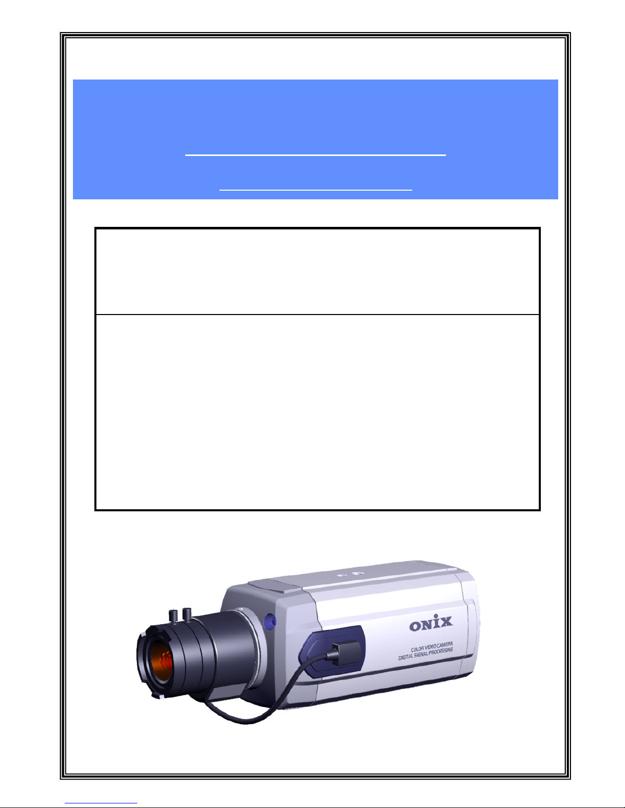
User’s Manual
INSTALLATION /
OPERATION
High Resolution Color CCD
HQ1 BOX Camera
ONS- 620N HQ1 DUAL
620N HQ1 FREE
620P HQ1 DUAL
620P HQ1 FREE
ONS- 620N HQ1 DUAL OSD
620N HQ1 FREE OSD
620P HQ1 DUAL OSD
620P HQ1 FREE OSD
1/28
Page 2

2/28
Important Safeguards and Warnings
Prior to installation and use of this product, the following warnings should be
observed.
1. Installation and service should be done only by qualified service and installation
personnel.
2. Installation shall be done in accordance with all local and national electrical and
mechanical codes utilizing only approved materials.
3. Use only UL listed class 2 power supply.
4. To prevent fire or shock hazard, do not expose this appliance to rain or moisture.
Regulatory Notices
This equipment has been tested and found to comply with limits for a Class A digital
device, pursuant to part 15 of the FCC Rules.
These limits are designed to provide reasonable protection against harmful
interference when the equipment is operated in a commercial environment.
This equipment generates, uses, and can radiate radio frequency energy and, if not
installed and used in accordance with the installation manual, may cause harmful
interference to radio communications operation of this equipment in a residential
area in which case the user will be required to correct the interference at his own
expense.
Warning – Change or modifications not expressly approved by the manufacturer
could void the user’s authority to operate the equipment.
Page 3

This document provides the main characteristics of the “ONS- 620N/P HQ1 DUAL
TDN Series” – high resolution Analog Color CCD BOX Camera.
This High Resolution Analog color CCD BOX Camera supports the output of
standard TV system mode “NTSC Type (ONS- 620N HQ1 DUAL Series) and PAL
Type (ONS-620P HQ1 DUAL Series).
Also, the quality of the ultimate output has been upgraded by using High Resolution
410K pixels CCD (Charge Coupled Device) and high resolution color signal
processor(HQ1) which can produce the finest quality of image.
The product is designed for applying the various Lens of C-Mount/CS-Mount,
Video/DC/ELC (Electronic Light Control) IRIS type, in order to meet the customer’s
need.
It became easy to satisfy the customer’s demand to produce the complete
manufactured camera by connecting to the Time Lapse VCR or DVR (Digital Video
Recorder) – which is a kind of storage tool for the form of complete manufactured
box type camera used for surveillance system.
Also, due to the UTP cable(CAT5) of the applied Camera power and video signal, it
has distinguished feature of easiness to install a UTP cable.
3/28
Description
Precautions
Use the camera under condition where temperatures are within -20℃ to 50℃.
Especially be careful for ventilation under high temperature.
Severe lighting flicker can cause the camera to work improperly.
Do not disassemble the camera.
Do not install or use the camera in an environment where the humidity is high.
Never use the camera close to a gas or oil leak.
Do not drop the camera or subject them to physical shocks.
Do not expose the camera to rain or spill beverage on it.
Never keep the camera face to strong light directly.
Do not touch the front glass of the camera.
<Notes>
If the camera is exposed to spotlight or object reflecting the strong light, the smear
or blooming may occur.
Please check the power whether it satisfies the normal specification before
connecting the camera.
Page 4

MODEL
TV
System
Function
OSD
Maximum
Resolution
Power
System
True
Day &
Night
ONS-620N HQ1 DUAL NTSC - 620 TV lines
24V AC/ 12V
DC
-o -
ONS-620N HQ1 Free NTSC - 620 TV lines
90V AC ∼ 240V
AC
-- -
ONS-620N HQ1 DUAL
TDN
NTSC - 620 TV lines
24V AC/ 12V
DC
oo -
ONS-620N HQ1 FREE
TDN
NTSC - 620 TV lines
90V AC ∼ 240V
AC
o- -
ONS-620N HQ1 DUAL
OSD
NTSC o 620 TV lines
24V AC/ 12V
DC
-o o
ONS-620N HQ1 FREE
OSD
NTSC o 620 TV lines
90V AC ∼ 240V
AC
-- o
ONS-620N HQ1 DUAL
TDN OSD
NTSC o 620 TV lines
24V AC/ 12V
DC
oo o
ONS-620N HQ1 FREE
TDN OSD
NTSC o 620 TV lines
90V AC ∼ 240V
AC
o- o
ONS-620P HQ1 FREE
TDN OSD
PAL o 610 TV lines
90V AC ∼ 240V
AC
o- o
ONS-620P HQ1 DUAL
TDN OSD
PAL o 610 TV lines
24V AC/ 12V
DC
oo o
ONS-620P HQ1 FREE
OSD
PAL o 610 TV lines
90V AC ∼ 240V
AC
-- o
ONS-620P HQ1 DUAL
OSD
PAL o 610 TV lines
24V AC/ 12V
DC
-o o
ONS-620P HQ1 FREE
TDN
PAL - 610 TV lines
90V AC ∼ 240V
AC
o- -
ONS-620P HQ1 DUAL
TDN
PAL - 610 TV lines
24V AC/ 12V
DC
oo -
ONS-620P HQ1 Free PAL - 610 TV lines
90V AC ∼ 240V
AC
-- -
ONS-620P HQ1 DUAL PAL - 610 TV lines
24V AC/ 12V
DC
-o -
UTP
Drive
RS485
Communication
-“HQ1” SONY DSP (Digital Signal Processor)
-”Super Dynamic CCD” (High Sensitivity CCD)
- High Resolution (620TV Lines) of Horizontal Resolution
- Easy Day & Night Function (Option)
- Easy to Install by OSD character (ONS-620 HQ1 OSD)
- Automatic Gain Control (AGC) On/Off
- Auto Tracking White Balance (ATW) and Manual Modes
- Backlight compensation On/Off
- Sync system Intern al / Li n e L oc k
- C&CS Mount Selectable
- Built in UTP Drive 2,000ft Twisted Pair Cable Transmitter
- EX-VIEW CCD Available (Option)
*. ONS-620 HQ1’s Series Feature Summary
4/28
Specifications
*. Design and specifications are subject to change without notice.
Page 5

Specifications
MODEL NO. ONS-620N HQ1
DUAL
ONS-620N HQ1 DUAL
TDN OSD
TERMINAL : DUAL VOLTAGE (10-36V DC and 18-30V AC) / UTP : 12-48V DC or 24V-28V AC
1/3” SONY SUPER Dynamic HAD Interline CCD
(NTSC)
SENSING AREA 6mm diagonally
LENS TYPE C/CS Mount Lens (adjustable)
MIN. ILLUMINATION
(AGC ON)
0.01 LUX Normal : 0.0001 LUX
Day & Night : 0.00001
LUX
0.01 LUX Normal : 0.0001 LUX
Day & Night : 0.00001
LUX
Internal / AC (Line Lock),
Auto Detect
RS – 485
OFF, 1~255(Total 255)
AUTO/ PUSH AUTO/
MANUAL/OUTDOOR/
INDOOR/ SPECIAL
AUTO/ MANUAL/ AGC
MANUAL/ IRIS MANUAL
- User TITLE : 20 Characters
- Sharpness etc.
FUNCTION / CAMERA ID /
USER TITLE / INIT TITLE
5.5W (Max) / 450mA
2:1 INTERLACE
525LINES / 60FIELDS / 30FRAMES
15.734 KHz
59.94 Hz
811(H) X 508(V) 410K
768(H) X 494(V) 380K
MORE THAN 50dB (AGC off)
More Than 620 TV LINES
Top or Bottom of camera housing
Internal / AC (Line
Lock)
BNC : 1 V p-p Composite Output 75 Ω Terminated / UTP : 2.0 V p-p Difference Composite Output 50 Ω Terminated
2,000ft Twisted Pair Cable Transmitter (Must be used with the UTP receiver)
Not Available
Not Available
AUTO
AUTO
External 3EA / Inner
10EA Function DIP
Switches
- MIRIS / ELC
- AGC ON/OFF
- BLC OFF/ON
Not Available
-4℉ ~122℉ (-20℃ ~50℃) , 0 %RH ~ 60 %RH
-4℉ ~158℉ (-20℃ ~ 70 ℃) , 0 %RH ~ 85 %RH
4.7W (Max) / 380mA
2.36(W) X 2.2(H) X 4.65(D) inches (60(W) X 56(H) X 118(D) mm)
ONS-620P HQ1
DUAL
ONS-620P HQ1
DUAL TDN OSD
POWER SOURCE
IMAGE PICK –UP
DEVICE
1/3” SONY SUPER Dynamic HAD Interline CCD
(PAL)
2:1 INTERLACE
625LINES / 50FIELDS / 25FRAMES
15.625 KHz
50 Hz
795(H) X 596(V) 470K
752(H) X 582(V) 440K
More Than 610 TV LINES
Internal / AC (Line
Lock)
Not Available
Not Available
AUTO
AUTO
External 3EA / Inner
10EA Function DIP
Switches
- MIRIS / ELC
- AGC ON/OFF
- BLC OFF/ON
Not Available
4.7W (Max) / 380mA
1.7 lb (770 g) (Without Lens)
SCANNING SYSTEM.
SCANNING
FREQUENCY(H)
SCANNING
FREQUENCY(V)
TOTAL PIXCEL NO.
EFFECTIVE PIXCEL
NO.
S / N RATIO
RESOLUTION
(HORIZONTAL)
CAMERA MOUNT
SYNC SYSTEM Internal / AC (Line Lock),
Auto Detect
VIDEO OUTPUT
UTP DRIVER
CAMERA CONTROL RS – 485
CAMERA ID OFF, 1~255(Total 255)
AWB SET
AUTO/ PUSH AUTO/
MANUAL/OUTDOOR/
INDOOR/ SPECIAL
AE SET
AUTO/ MANUAL/ AGC
MANUAL/ IRIS MANUAL
SPECIAL SET
- User TITLE : 20 Characters
- Sharpness etc.
OSD DISPLAY
FUNCTION / CAMERA ID /
USER TITLE / INIT TITLE
OPERATION
TEMPERATURE
STORAGE
TEMPERATURE
POWER
CONSUMPTION
5.5W (Max) / 450mA
DIMENSION
WEIGHT
5/28
Page 6
6/28
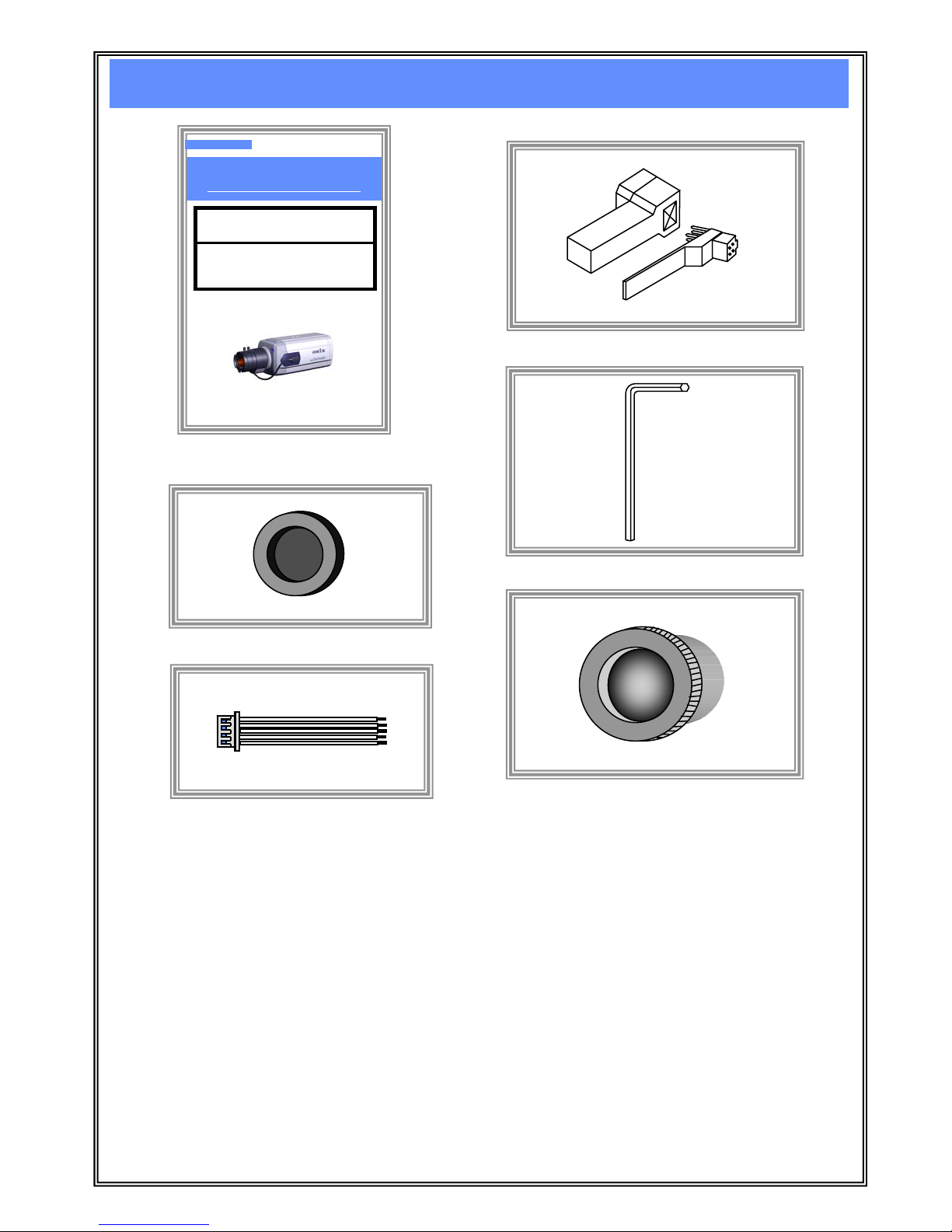
Accessories
User’s Manual
INSTALLATION / OPERATION
ONS- 620N HQ1 DUAL
620P HQ1 DUAL
ONS- 620N HQ1 DUAL OSD
620P HQ1 DUAL OSD
High Resolution Color CCD HQ1
BOX Camera
You Talk, We Listen
Installation/Operation manual
Iris Lens Plug
C-Mount Lens Adapter
L-Wrench
Glass Protecting Cap
Glass Protecting cap
---- Be sure to cap the lens mount when the lens is not mounted.
Pull out the cap to remove.
C-Mount lens Adapter ---- Use to attach a C-mount lens.
CS-mount lens can be used when the CS-mount adapter is attached, and C-mount
lens can be used when it is removed.
Back Focus Lock L-Wrench ---- Use to lock a CS-mount adapter or C-mount adapter.
Refer to the section on “Lens Mounting”.
Iris Lens Plug ---- Use to connect auto iris lens plug.
Refer to the section on “Lens Mounting”.
Remote Plug ---- Use to connect for remote connector. For ONS-620 HQ1 OSD series only.
Remote Plug (For ONS-620 OSD series only)
Page 7
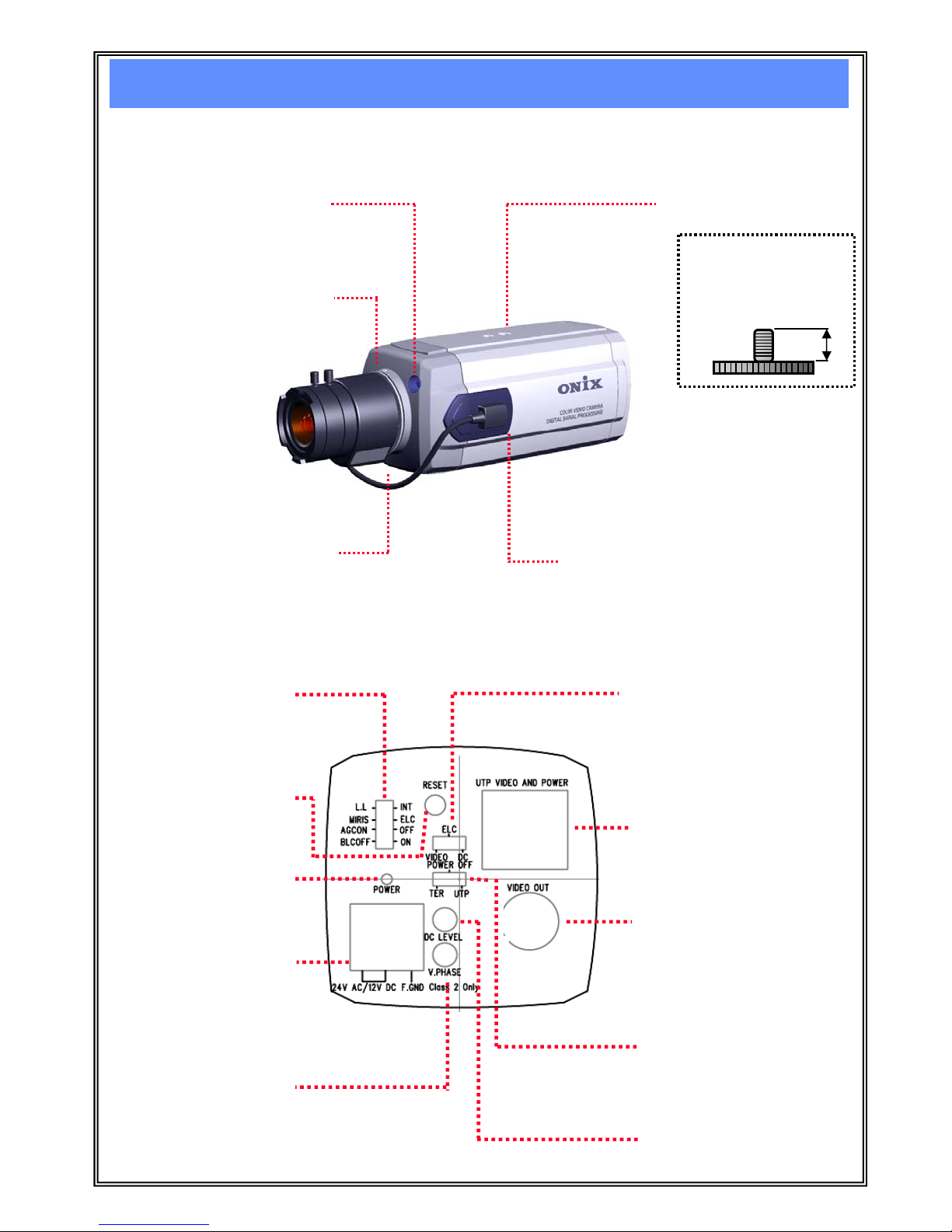
<Front Layout>
①. Window for TDN
(True Day & Night)
CdS Sensor
②. Back focus adjustment
locking Wrench.
③. Back focus adjustment
Ring. (CS-mount adapter)
④. Camera Mount
Adapter.
⑤. LENS Connector.
7/28
Camera Layout
<Rear Layout (ONS-6 20 HQ1 series)>
⑥. DIP Switches
⑦. LENS Mode Select Switch
⑧. RJ-45 Modular JACK for
UTP Cable
⑨. Composite Video Output
BNC Connector
⑩. Camera Power Select
Switch
⑪. LENS Level
Adjustment
⑫. AC Phase
Adjustment
⑬. Power Terminal
Connector
⑭. Power LED
⑮. RESET Key
<Screw Specification>
1/4”-20 UNC (20 THREAD)
L : 4.5mm ± 0.2mm
(ISO Standard)
or 0.197”(ASA Standard)
L
Page 8
The camera can use a fixed iris, manual iris or auto iris lens. The ca mera has factory set for a CS-mount lens, but
it adjust for a C-mount lens easily.
1). C-mount Lens Only ---- Attach the C-mount adapter by rotating clockwise before installing the C-mount lens
(The C-mount adapter offered accessory).
*. Installing CS-mount Lens -> After removing the protecting cap, attach the lens into
the camera by truing clockwise.
Installing C-mount lens -> Remove the protecting cap and CS-mount adapter.
Attach the lens into the camera by turning clockwise.
2). LENS Mode Select ---- Set the lens mode selector switch on the rear of the camera to VIDEO (auto iris video
drive lens) or DC (auto iris DC drive lens). Switch setting is determined by the type
of lens used.
3). Back Focus Adjustment ---- a. Loosen the back focus adjustment wrench② (one on top).
b. Turn the back focus adjustment ring③ until the object is in focus.
c. When the back focus adjustment is satisfactory, tighten the locking wrench② or
force the back focus adjustment ring③.
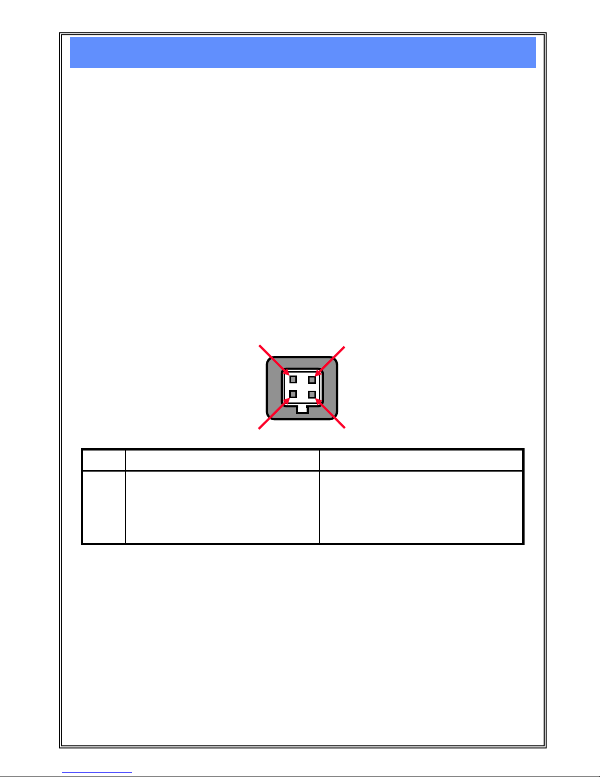
4). Connect LENS ---- Connect the auto iris lens to the four-pin connector⑤ located on the side of camera.
Pin connections for the iris drive connector are as follows:
< LENS MOUNTING>
PIN DC auto iris LENS VIDEO auto iris LENS
1
2
3
4
Control coil negative(-)
Control coil positive(+)
Drive coil positive(+)
Drive coil negative(-)
Lens positive supply
Not used
Video drive signal
Ground
1
2
3
4
8/28
Installation
The mount adapter④ may be fitted to the top or bottom of the camera.
<CAMERA MOUNTING>
The window① into the CdS (Cadmium Sulfide) Sensor for TDN (True Day & Night) function.
<Day & Night Sensing window>
*. Lens is not supplied with this camera. Purchase the suitable lens for your environment.
This camera accepts auto iris lens, both C and CS-mount lens.
If the lens is stained with fingerprint or something, the image quality might be poor. It is recommended
to use a high quality lens to improve the image quality under low illumination.
Page 9
9/28
<Composite Video Output BNC⑨ Connector>
Connect a video cable to the SIGNAL OUT connector (BNC) on the back of the camera.
75 ohms impedance composite video signal output.
Connect the video output jack to the monitor video input jack.
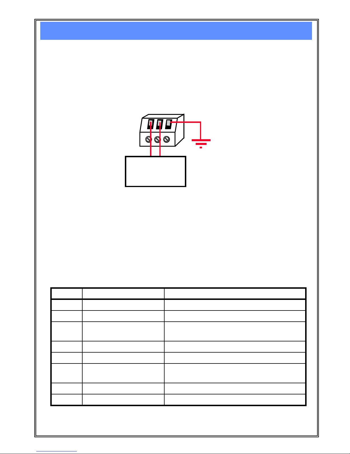
<Power Terminal Connector ⑬>
24V AC/12V DC ---- Use the class2 isolated supply only.
Connect the power cable to the two-pin power connector on the back of the
camera using the terminal block connector.
FG
--- Frame GND. Connect the Earth.
*. Connecting method for AC power type : The wire is no polarized. / Use 24V AC 60Hz(NTSC),
use 24V AC 50Hz(PAL).
Connecting method for DC power type : The wire is no polarized. / Use 12V DC.
*. Be sure to connect power after all the installation has been done.
Note that AC adapter is not supplied with camera.
Class2
Isolated Power
Supply
(24V AC or 12V DC)
FG
*. If the camera power is offered through the UTP cable than the camera power selects
to “UTP” position. Refer to the section on “Camera Power Select Switch”.
<Power LED⑭ Indicator>
LED (RED)---- The LED on the back panel of camera indicates that power is connected.
Power and Video Connections
Pin NO Name Description
1 Video + UTP Transmitted video signal +
2 Video - UTP Transmitted video signal -
3
Rx+ or Tx+ Control Data RS485 Receive+ (or Trans+) data
(For ONS-620 HQ1 OSD Series only)
4 GND or 24~28V AC- Power GND or AC power 5 12-48V DC or 24~28V AC+ 12-48V DC or 24V-28V AC Power Supply input
Rx- or Tx-
12-48V DC or 24~28V AC+
GND or 24~28V AC-
6
Control Data RS485 Receive- (or Trans-) data
(For ONS-620 HQ1 OSD Series only)
7 12-48V DC or 24V-28V AC Power Supply input
8 Power GND or AC power -
<RJ-45 Modular JACK⑧ for UTP cable>
Page 10

INT/L.L : Internal / Line Lock
Line Lock
---- Locked the vertical frame to the power supply frequency.
Eliminate vertical roll caused by multiple cameras connected to the same switching
device.
Internal (Default setting)
--- Lock the vertical frame to the internal oscillator. Use with DC or
unstable AC.
MIRIS/ELC : Mechanic iris / Electronic shutter speed Light Control
Mechanic iris
--- Disable the ESC (Electronic Shutter speed light Control).
The switch setting is determined by the type of lens used the video controlled
auto iris and DC controlled auto iris lens. Electronic shutter speed is fixed 1/60sec
or 1/50sec (Flicker less : 1/100sec or 1/120sec).
ELC (default setting)
--- Enable ESC mode. The ESC function automatically change the sensitivity
of the camera by varying the electronic shutter speed according to the
amount of incident light.
Electronic shutter speed range is 1/60sec(1/50sec) to 1/100,000sec.
<DIP Switches ⑥ Setting only ONS-620 HQ1 Series>
10/28
Mode switches
<LENS MODE Select Switch⑦ Setting>
ELC --- Disable the Video controlled Auto iris mode and the DC controlled
Auto iris mode.
VIDEO
--- Enable the Video controlled Auto iris mode.
DC (Default setting)
--- Enable the DC controlled Auto iris mode.
ELC
VIDEO
DC
<Camera Power Select Switch ⑩>
POWER OFF --- BOX Camera Power Off Mode.
The BOX Camera Power is not offered.
TER (Default setting)
--- USE TERMINAL POWER.
Enable the BOX Camera offered through the terminal⑬.
UTP
--- USE RJ45 UTP POWER.
Enable the BOX Camera offered through the UTP cable⑧.
POWER OFF
TER
UTP
AGCON/OFF : Gain up Mode setting of Auto Gain Control.
OFF
---- Disable the AGC mode.
AGCON (Default setting)
---- Automatically process the image to gain up under low light condition.
BLCOFF/ON : Back Light Compensation mode setting.
ON
---- Enable the BLC mode. If a bright backlight is present, the objects in the picture may
appear dark or as a silhouette. BLC enhances objects in the center of the picture.
BLCOFF (Default setting)
---- Disable the BLC mode.
Page 11

<LENS Level Adjustment Volume⑪>
DC LEVEL ---- Rotate the LENS Level adjustment volume⑪ until to get the enhanced object image.
Used to adjust video output level of DC driven auto iris lens.
When the brightness control of the monitor does not operate correctly, you can get
the optimum picture by controlling the DC level of camera.
<AC Phase Adjustment Volume⑫>
V. PHASE ---- Rotate the AC phase adjustment volume⑫ until to get the enhanced object image and
lock the vertical frame to the power supply frequency.
If the camera is to be used in the L.L mode, the vertical phase may require adjustment
to synchronize the vertical phase of the camera with other camera in the system.
Make this adjustment when the vertical phase of the camera does not match with other
cameras or systems. For correct adjustment, use a multi-channel oscilloscope.
The V.PHASE adjustment can be readjusted in the range of 0 to 360 degrees.
-. This adjustment is necessary only when line lock is performed.
-. There is a LL mode select switch on the rear.
-. The LL mode can be used in the areas of 60Hz (NTSC models), 50Hz(PAL models) power
frequency.
<Camera RESET KEY button ⑮>
RESET (TACT) ---- Push the reset button to change the Internal / Line Lock mode setting⑥
for the camera sync system.
Push the reset button to restart the camera that it do start of power on.
11/28
Tact switch & Volumes
Monitor picture Adjustment direction
To make it brighter Turn clockwise
To make it darker Turn counterclockwise
Page 12

ONS-620 HQ1 Series RJ-45Jack
Pin Description Pin NO
Video + 1
Video -
Rx+ , Tx+
GND or 24~28V AC-
12-48V DC or 24~28V AC+
Rx- , Tx-
12-48V DC or 24~28V AC+
GND or 24~28V AC-
2
3
5
4
7
6
8
Rx- , Tx-6
12-48V DC or 24~28V AC+5
Rx+ , Tx+3
Video -2
Video +1
GND or 24~28V AC-8
12-48V DC or 24~28V AC+7
GND or 24~28V AC-4
Pin DescriptionPin NO
Receiver ONU-2000 RJ-45 Jack
Twisted Pair UTP Cable
12/28
UTP cable Description
UTP
power
Not use
Under 500ft
(under 150m)
●
4
about
24V DC
or
24V AC
Under 150ft
(under 50m)
VIDEO /
RS485 /
POWER
●
3
Under 1,500ft
(under 500m)
●
5
Under 2,000ft
(under 600m)
●
6
VIDEO /
RS485
VIDEO
only
via UTP
Cable
signal
2
1
NO
UTP POWER SUPPLY
(DUAL POWER)
Under 4,000ft
(under 1.2 Km)
MAX 6,000ft
(MAX 2Km)
Local
power
under
48V
DC
about
35V DC
or
28V AC
over
12V DC
CAMERA
POWER
Guarantee
UTP CABLE
Length
*. LOCAL POWER : Camera Power supply (12V DC or 24V AC)
UTP POWER : Use AC (MAX 28V AC) or DC `p ower (MAX 48V DC)
*. Design and specifications are subject to change without notice.
Page 13

<Select UTP power Switch and Select UTP Cable Length>
Switch Mode select the “UTP”.
Enable the BOX Camera offered through the UTP
cable⑧.
*. Rotated the “Frequency EQ.” and “VIDEO AMP GAIN” adjustment volume until to get the
enhanced object image thought the UTP Cabl e video signal.
13/28
UTP Receiver (ONU-2000) Description
*. UTP Receiver(ONU-2000) can be supplied an order.
<ONU-2000 (Receiver)> *. Enable RS485 communication.
Page 14

14/28
Installation “UTP Receiver (with ONU-2000)”
Composite
VIDEO
OUTPUT
UTP (Cat.5) Cable Receiver ONU-2000
RJ-45
RS485
Tx+ / Tx-
LOCAL POWER Supply
(DUAL Power 24V AC or 12V DC)
LOCAL POWER Supply
(DUAL Power 24V AC or 12V DC)
MAX 4,000ft (1.2Km)
UTP Cable (CAT5)
Frequency EQ.
Video AMP GAIN
<ONU-2000 (Receiver) for MAX 4,000ft (1.2Km) Cable with l o ca l power supply >
BOX UTP Series Model
*. The Power Select Switch selects “UTP OFF”.
*. Turn “Frequency EQ.” and “Video AMP GAIN”
volume element rotate until enhan ce the object picture.
To Terminal
To RJ45
UTP
Page 15

15/28
Installation “UTP Receiver (with ONU-2000)”
Composite
VIDEO
OUTPUT
*. Turn “Frequency EQ.” and “Video AMP GAIN”
volume element still enhances objects in the picture.
UTP (Cat.5) Cable Receiver ONU-2000
RJ-45
*. The Power Select Switch selects “TO UTP”.
RS485
Tx+ / Tx-
Frequency EQ.
Video AMP GAIN
<ONU-2000 (Receiver) for MAX 2,000ft (600M) Cable with UTP power supply >
BOX UTP Series Model
To RJ45
UTP
*. UTP Adaptor(35V DC 570mA) can be supplied an order.
UTP POWER Supply Adaptor
(12V DC ∼ 48V DC or 24V AC ∼ 28V AC power)
<UTP Cable (CAT5) length>
12V DC power : under 150ft (50M)
24V DC power : under 500ft(150M)
35V DC power : under 1,500ft(500M)
48V DC power : under 2,000ft(600M)
24V AC power : under 500ft(150M)
28V AC power : under 1,500ft(500M)
Page 16

16/28
Installation “UTP Driver (with ONU-1000)”
<USE LOCAL POWER and RS485 Control
(Composite Video & 12V DC power Analog Cameras)>
UTP (Cat.5) Cable Driver ONU-1000
12V DC POWER
VIDEO
UTP (Cat.5) Cable Receiver ONU-2000
Composite
VIDEO
OUTPUT
RJ-45
RJ-45
CONTROL
RS485
RX+/Rx-
RS485
Tx+ / Tx-
Frequency EQ.
Video AMP GAIN
LOCAL POWER Supply
(DUAL Power 24V AC or 12V DC)
LOCAL POWER Supply
(DUAL Power 24V AC or 12V DC)
*. Turn “Frequency EQ.” and “Video AMP GAIN”
volume element still enhances objects in the picture.
*. The Power Select Switch selects “UTP OFF”.
*. The Power Select Switch selects “From LOCAL”.
Frequency EQ.
MAX 4,000ft (1.2Km)
UTP Cable (CAT5)
Page 17

17/28
Installation “UTP Driver (with ONU-1000)”
<USE UTP POWER and RS485
(Composite Video & 12V DC power Analog Cameras)>
Composite
VIDEO
OUTPUT
UTP (Cat.5) Cable Receiver ONU-2000
RJ-45
12V DC POWER
VIDEO
UTP (Cat.5) Cable Driver ONU-1000
RJ-45
CONTROL
RS485
RX+/Rx-
RS485
Tx+ / Tx-
Frequency EQ.
Video AMP GAIN
*. The Power Select Switch selects
“From UTP”.
*. Turn “Frequency EQ.” and “Video AMP GAIN”
volume element still enhances objects in the picture.
*. The Power Select Switch selects “To UTP”.
Frequency EQ.
*. UTP Adaptor(35V DC 570mA) can be supplied an order.
UTP POWER Supply Adaptor
(12V DC ∼ 48V DC or 24V AC ∼ 28V AC power)
<UTP Cable (CAT5) length>
12V DC power : under 150ft (50M)
24V DC power : under 500ft(150M)
35V DC power : under 1,500ft(500M)
48V DC power : under 2,000ft(600M)
24V AC power : under 500ft(150M)
28V AC power : under 1,500ft(500M)
Page 18

No Name Location Mode Function
AWB1 AWB2
on on
on
on
on
off
off
off
off
SEL1 SEL2 SEL3
on on
on off
off on
off off
on on
on off
off on
off off
8 AEREF Off Auto Exposure AE reference Level. Off : 120 IRE / On : 100IRE
9 Mirror On Mirror image Mirror image output. Of f : Mirror / On : Normal
Mode Manual shutter speed set mode
on auto Auto shutter mode
5
6
7
SHTSEL1
SHTSEL2
SHTSEL3
on 1/100(1/120) 1/100sec shutter speed fixed NTSC. (PAL :1/120)
on 1/250 1/250sec shutter speed fixed.
on 1/500 1/500sec shutter speed fixed.
off 1/1,000 1/1,000sec shutter speed fixed.
off 1/2,000 1/2,000sec shutter speed fixed.
off 1/4,000 1/4,000sec shutter speed fixed.
off 1/10.000 1/10,000sec shutter speed fixed.
10 FLCOFF On Flicker less Flicker less function. Off : Enable / On : Disable
on
off
off
on
on
off
off
On (default setting)
AWB3 Mode White balance mode
on ATW Auto W/B mode (Default Setting)
off Manual Manual (White Balance Gain R /B up down Key Enable)
on Push “On Time” : operation AWB, “Off” : hold AWB
off Hold LOCK by Push mode White Balance Data stored in the memory
on Outdoor 1 4700ºK Fixed Value white balance gain
off Indoor 1 3200ºK Fixed Value white balance gain
1
2
3
AWB1
AWB2
AWB3
on Indoor 2 4200ºK Fixed Value white balance gain
off Outdoor 2 6300ºK Fixed Value white balance gain
4 Anti CR Color-rolling less
Anti-Color-rolling AWB operation (ignored AWB1/AWB2/AWB3)
Off : Enable / On : Disable
< DIP Switches (only ONS-620 HQ1 Series)>
DIP switch location
1 2 3 4 5 6 7 8 9 10
Off
On
DIP switch Function
18/28
Inner mode switch
Page 19

<Rear Layout (ONS-620 HQ1 OSD series)>
Ⓐ. Function Setup
TACT Switches
Ⓑ. REMOTE Connector
*. For more information, please refer to the front pages with “Camera Layout”.
19/28
ONS-620 HQ1 OSD Series Camera Layout
<ONS-620 FREE>
&
<ONS-620 w/o UTP>
<ONS-620 FREE OSD>
&
<ONS-620 OSD w/o UTP>
Page 20

<Function Setup TACT Switches Ⓐ>
< REMOTE Connector Ⓑ>
Function key application by OSD (On Screen Display).
---- The button transferred the selected OSD to Left .
MENU
---- Enable MENU mode. The displayed to the OSD (On Screen display) menu.
---- The button transferred the selected OSD to right.
T( )
---- The button transferred the selected OSD to up.
<In case of using digital zoom function>
Push this button to “Zoom In”, to the tele field of view.
W( ) ----The button transferred the selected OSD to down.
<In case of using digital zoom function>
Push this button to “Zoom Out”, to the wide field of view.
Pin NO Name Description
1 R+ RS485 Communication Receive+ data
2 R- RS485 Communication Receive- data
3 D&N
Day & Night control out (‘H’= Night)
4 GND Control GND
5 ALARM
Alarm Out (‘H’ Out)
*. DVR Interface(RS485)
R+
R-
TRX+
TRX-
ALARM
ALARM
GND
D&N
IR LED Illuminator
5V/10mA
It is a terminal that controls the function of the camera at long distance.
The pin3(D&N) output the IR LED lamp on control signal by selecting the sensitivity of the CdS
sensor for Day & Night function. It is ‘H’ status output on the night mode.
The pin5(ALARM) is the motion detection output signal. It is ‘H’ status output on the recognition
mode.
20/28
ONS-620 HQ1 OSD Series
0V
0 V
Day mode
2.5sec over
+4.0V ∼ +5.0V
Night mode
0 V
Motion nothing
2.5±0.5sec
+4.0V ∼ +5.0V
Motion detection
Function Command data Byte
MENU AA,EE,0F,CC,55 5
AA,EE,1E,CC,55 5
AA,EE,1D,CC,55 5
AA,EE,1B,CC,55 5
AA,EE,17,CC,55 5
<RS-485 Communication set>
-. Data Bit : 8 -. Bit/sec : 9600bps
-. Stop Bit : 1 -. Parity : None
-. Please camera power off to connect or disconnect “REMOTE” connecter.
-. Don’t connect to not used pin in the “REMOTE connecter.
Page 21

< OSD (On Screen Display) Functions (ONS-620 HQ1 OSD Series Only)>
TACT Switch actions of the REAR Panel
CAMERA software
RESET
“MENU” frame display
Shift LEFT
&
Mode change
Shift Right
&
Mode change
MENU /
Select /
Return /
Enter
Shift up
&
Menu change
Shift down
&
Menu change
21/28
ONS-620 HQ1 OSD Series OSD Description
VIDEO/DC (VIDEO/DC, ELC)
Set by the type
of lens used.
Page 22

“C.BALANCE” frame display (Chroma balance)
PUSH AUTO
(PUSH AUTO, AUTO, MANUAL)
0 (-3 to +3)
0 (-3 to +3)
OFF (ON,OFF)
OFF (ON,OFF)
If AUTO WB is Off
then enable menu
“EFFECT” frame display
0 (-3 to +3)
0 (-3 to +3)
OFF (ON,OFF)
OFF (ON,OFF)
OFF (ON,OFF)
Return initial value
Exit the this menu
REAR ’s
CONTROL
CONNECTOR
output
control
OFF (LOW,MID,HIGH,OFF)
*. HLBM : High Light Black Mask BLC function
22/28
ONS-620 HQ1 OSD Series OSD Description
initial value (Variable Range)
Return initial value
Exit the this menu
*. AUTO WB AUTO : Auto Tracking White balance Mode.
So the auto white balance can’t display
on the special lighting or illuminator.
Page 23

“DAY/NIGHT” frame display
OFF (ON,OFF)
+3 (-3 to +3)
+2 (-3 to +3)
0 (-3 to +3)
Night filter mode 1time
Action
If TRUE D/N is ON
then enable Menu.
0 (-3 to +3)
REAR ’s
CONTROL
CONNECTOR
output
control
“EXPOSURE” frame display
0 (-3 to +3)
AUTO (☞)
OFF (ON,OFF)
0 (-3 to +3 or D/N)
1E0 (000 to 3FF)
Auto (ELC)
1/60(50)
1/100(1/120)
1/250
1/500
1/1,000
1/2,000
1/4,000
1/10,000
OFF (ON,OFF)
10 SEC (☞)
23/28
ONS-620 HQ1 OSD Series OSD Description
BW start point – Set the start point that transform into BW mode.
BW end point – Set the recover point of the chrome mode.
If this setting value is “+3” than it’s color mode.
So can not go to B/W mode.
SPRS Start – Set the start point of aperture suppress.
SPRS END – Set the recover point unsuppressed mode
FILTER B/W – Set the B/W (Black & White) Image on the True Day & Night ON mode.
Fixed AUTO shutter
speed that “LENS
TYPE” is ELC mode.
But controls shutter
speed that “LENS
TYPE” is VIDEO/DC
mode only.
0 SEC
2 SEC
5 SEC
10 SEC
20 SEC
30 SEC
60 SEC
*. AGC MAX SET : Fixed value “D/N”(+3 value) on the TRUE D/N mode of “DAY/NIGHT” function.
And the variable range change “+1” to “+3” on the “FLICKERLESS”
mode “ON” state.
OFF (ON,OFF)
Page 24

“UTP” frame display
50M UNDER (50M UNDER,
100M, 600M, 1KM, MANUAL)
65 (65∼75)
OFF (ON,OFF)
“PRIVACY” frame display
OFF (ON,OFF)
24/28
ONS-620 HQ1 OSD Series OSD Description
0 (-3 to +3)
0 (-3 to +3)
1 (1 to 8)
OFF (ON,OFF)
H.MOVE
(V.MOVE, H.SIZE, V.SIZE, H.MOVE)
If MASK SHOW is ON
then enable Menu.
“↔”
18F9 003C 0032 18EF
Display “MOVE/SIZE” data.
Set level of MANUAL.
Long distant is 75 value.
Change “MOVE/SIZE” data
If UTP SETUP is ON
then enable menu.
Page 25

“OSD” frame display
HIDE (SHOW,HIDE)
Set the user character.
maximum 20 characters.
1 (OFF, 1 to 255)
25/28
ONS-620 HQ1 OSD Series OSD Description
Its characters
selected by user.
Toggle display
until to be set.
HIDE (SHOW,HIDE)
OSD Text Table
A B C D E F G H I J K L M N O P Q R S T U V W X Y Z
0 1 2 3 4 5 6 7 8 9 blank ! # & ( ) * + , - . / : < = >
? [ ]
Enter the selected character by
the “UP(▲)/DOWN(▼)” key.
And change the characters by
“LEFT(◀)/RIGHT(▶)” key.
Page 26

26/28
Troubleshooting
If you experience a trouble of the camera, please refer to the following table.
If the guideline is not enough to solve the problem, please contact the
authorized technician.
Problems solutions
Nothing appears on the screen. -. Check the power connection and the cable
connection between the camera and monitor has
been made properly.
-. Check the TER/UTP selection switch on the rear of
the camera.
-. Check the DC/VIDEO selection switch on the rear
of the camera set to a proper position according to
the type of the auto iris lens.
The image on the screen is dark. -. Adjust DC level properly.
The image on the screen is dim. -. Check if the lens are stained or dirty. Clean up the
lens with soft clear cloth.
-. Check Vari-focal Lens’s focus adjustment method.
The contrast on the screen is too weak. -. Adjust the contrast feature of the monitor. If the
camera is exposed under the strong light then
change the position.
-. Adjust the Frequency EQ button of the UTP
receiver and V.PHASE button on the rear in the
camera with UTP Driver.
The image on the screen flickers. -. Dose the camera face directly to the sun or
fluorescent lighting?
If so, change the camera position.
-. Check the DC/VIDEO selection switch on the rear
of the camera set to the proper position according to
the type of the auto iris lens.
The image on the screen is distorted. -. Check if you have used 50Hz or 60Hz in line lock
mode.
If the power frequency is out of 50Hz or 60Hz, the
line lock synchronization mode cannot be used.
Change the synchronization mode to INT Mode.
The camera is not work properly, and the
surface of the camera case is hot.
-. Check if you have connected the camera to proper
power.
The color of the picture is not matched. -. Check if you have properly set the White Balance
Control Mode.
<Focus adjust Method with the Vari-focal type LENS>
step1. First adjust the wide angle of view by “T↔W” lever.
step2. Second adjust until the smallest image setting of Lens DC level volume on camera rear.
(Than camera image on the screen go to dark image but not black.)
step3. Last adjust focus of lens by “∞↔N” lever.
And adjust until best Image setting of step2 that backs DC level volume.
Page 27

(unit : mm)
27/28
Dimensions
Page 28

28/28
Manual Addendum
Correct Disposal of This Product
(Waste Electrical & Electronic Equipment)
(Applicable in the European Union and other European countries with separate
collection systems)
This marking shown on the product or its literature, indicates that it should not be
disposed with other household wastes at the end of its working lift. To prevent
possible harm to the environment or human health from uncontrolled waste disposal,
please separate this from other types of wastes and recycle it responsible to promote
the sustainable reuse of material resources.
Household users should contact either the retailer where they purchased this product,
or their local government office, for details of where and how they can take this item
for environmentally safe recycling.
Business users should contact their supplier and check the terms and conditions of
the purchase contract.
This product should not be mixed with other commercial wastes for disposal.
This device complies with Part 15 of the FCC Rules.
Operation is subject to the following two conditions : (1) this device
may not cause harmful interference, and (2) This device
must accept any interference received, including interference
that may cause undesired operation.
Made in Korea
 Loading...