

Page 1
Car Stereo
Car CD/CD-R/CR-RW Compatible/AM/FM 2 Band Radio
Model Number AN-8006
After Sales Support
TEL: 1300 886 649
Made in China
INSTRUCTION MANUAL
N13275
Page 2

After Sales Support TEL: 1300 886 649
1
What your 1 year warranty means
Congratulations on choosing to buy a ONIX product.
All products brought to you by ONIX are manufactured to the
highest standards of performance and safety, and, as part of our
philosophy of customer service and satisfaction, are backed by
our comprehensive 1 Year Warranty.
We hope you will enjoy using your purchase for many years to
come.
Car Stereo
Page 3

After Sales Support TEL: 1300 886 649
2
1 What your 1 year warranty means
2 Contents
3 Installation
7 Using the detachable front panel
8 Wiring Diagram
9 Operations
9 Location and Function of Keys
11 Using the Remote Control
13 General Operations
18 Radio Operations
20 CD/MP3 Operations
24 Mixed-Mode CDs Operations
25 SD/MMC Memory Card Play Operations
25 AUX in Operations
26 USB Device Operations
27 Disc Notes
30 Specications
31 Important notes
32 FAQ’s
Contents
Page 4

After Sales Support TEL: 1300 886 649
3
NOTES:
- Choose the mounting location where the unit will not interfere with
the normal driving function of the driver.
- Before nally installing the unit, connect the wiring temporarily
and make sure it is all connected up properly and the unit and the
system work properly.
- Use only the parts included with the unit to ensure proper installation. The use of unauthorised parts can cause malfunctions.
- Consult with your nearest dealer if installation requires the drilling of
holes or other modications of the vehicle.
- Install the unit where it does not get in the driver’s way and cannot
injure the passenger if there is a sudden stop, like an emergency
stop.
- If installation angle exceeds 30° from horizontal, the unit might not
give its optimum performance
- Avoid installing the unit where it would be subject to high
temperature, such as from direct sunlight, or from hot air, from
the heater, or where it would be subject to dust, dirt or excessive
vibration.
Din Front/Rear-Mount
This unit can be properly installed either from ‘Front’ (conventional
DIN Front-mount) or ‘Rear’ (DIN Rear-mount installation, utilising
threaded screw holes at the sides of the unit chassis).
For details, refer to the following illustrated installation methods.
Take out the screw before installation:
Installation
Before installing the unit,
please remove the two screws.
Page 5

After Sales Support TEL: 1300 886 649
4
Installation
1. DIN FRONT-MOUNT (Method A)
Installation Opening
This unit can be installed in any dashboard having an opening as
shown below:
Installing the unit:
Be sure you test all connections rst, and then follow these steps to
install the unit.
1. Make sure the ignition is turned o, and then disconnect the cable
from the vehicle battery’s negative (-) terminal.
2. Disconnect the wire harness and the antenna.
3. Press the button on the front panel and remove the control panel
(For details, refer to ‘using the detachable front panel’).
4. Lift the top of the outer trim ring then pull it out to remove it.
5. The two supplied keys release tabs inside the unit’s sleeve so you
can remove it. Insert the keys as far as they will go (with the notches
facing up) into the appropriate slots at the middle left and right
sides of the unit. Then slide the sleeve o the back of the unit.
53mm
182m m
WARNING: This unit must be installed by a professional
technician only or the warranty will be void.
Page 6
After Sales Support TEL: 1300 886 649
5
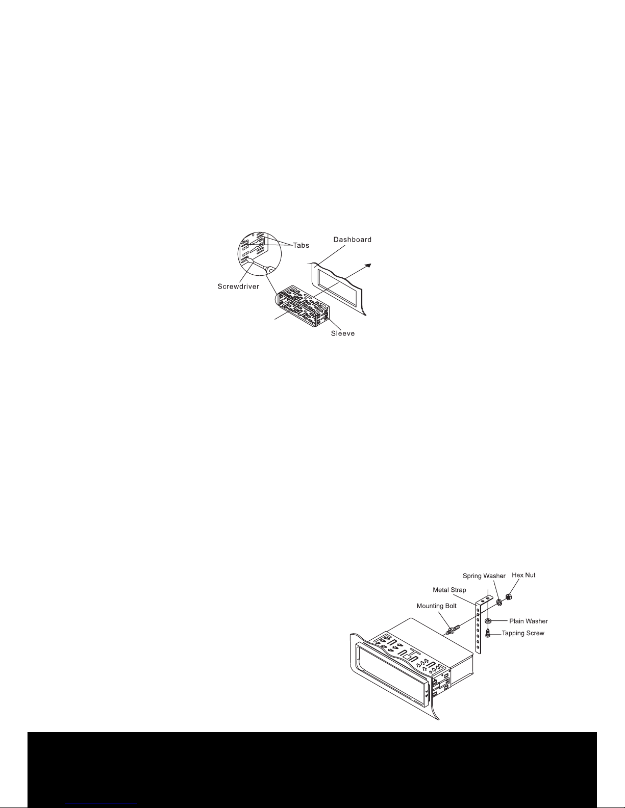
6. Mount the sleeve by inserting the sleeve into the opening of the
dashboard and bend open the tabs located around the sleeve with
a screwdriver. Not all tabs will be able to make contact, so examine
which ones will be most eective. Bend open the appropriate tabs
behind the dashboard to secure the sleeve in place.
7. Reconnect the wire harness and the antenna and be careful
not to pinch any wires or cables.
8. Slide the unit into the sleeve until it locks into place.
9. To further secure the unit, use the supplied metal strap to secure
the back of the unit in place. Use the supplied hardware (Hex Nut
(M5mm) and Spring Washer) to attach one end of the strap to the
mounting bolt on the back of the unit. If necessary, bend the metal
strap to t your vehicle’s mounting area. Then use the supplied
hardware (Tapping Screw (5x25mm) and Plain Washer) to attach
the other end of metal strap to a solid metal part of the vehicle
under the dashboard. This strap also helps ensure proper electrical
grounding of the unit.
Install the short threading terminal
of the mounting bolt to the back of
the unit and the other long threading
terminal to the dashboard.
Installation
Page 7
After Sales Support TEL: 1300 886 649
6
10. Reconnect the cable to the vehicle battery’s negative (-) terminal.
Then replace the outer trim ring and install the unit’s front panel
(see the steps of ‘to install the front panel’).
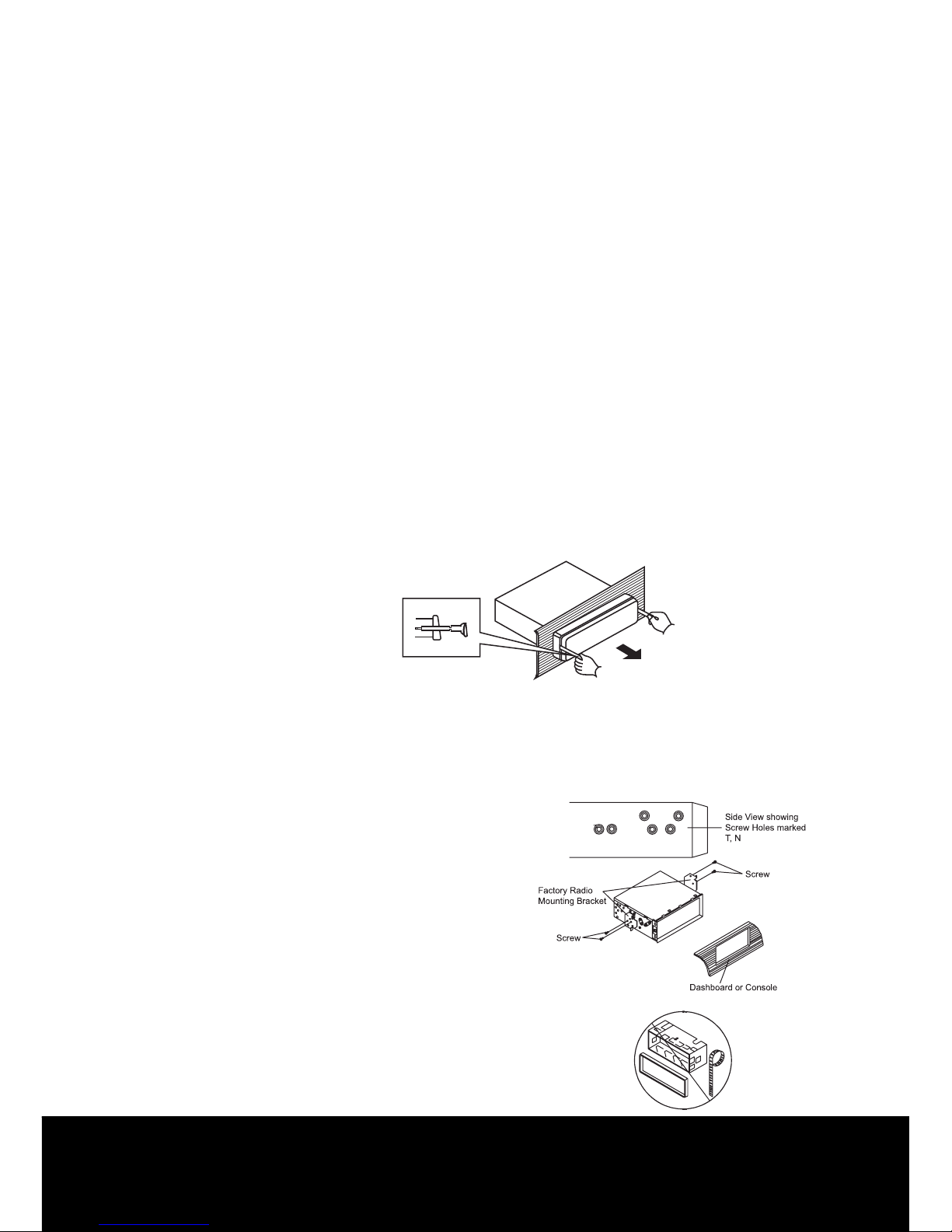
Removing the unit:
1. Make sure the ignition is turned o, and then disconnect the cable
from the vehicle battery’s negative (-) terminal.
2. Remove the metal strap attached to the back of the unit (if attached).
3. Press the release button to remove the front panel.
4. Lift the top of the outer trim ring then pull it out to remove it.
5. Insert both of the supplied keys into the slots at the middle left and
right sides of the unit then pull the unit out of the dashboard.
2. DIN REAR-MOUNT (Method B)
If your vehicle is a Nissan, Toyota, follow this mounting instruction.
Use the screw holes marked T (Toyota), N (Nissan) located on both
sides of the unit to fasten the unit to
the factory radio mounting brackets
supplied with your vehicle. Fasten the
unit to the factory radio mounting
brackets. Align the screw holes on
the bracket with the screw holes on
the unit, and then tighten the screws
(5x5mm) on each side.
NOTE: The outer trim ring, sleeve
and the metal strap are not used for
method B installation.
Installation
Page 8
After Sales Support TEL: 1300 886 649
7
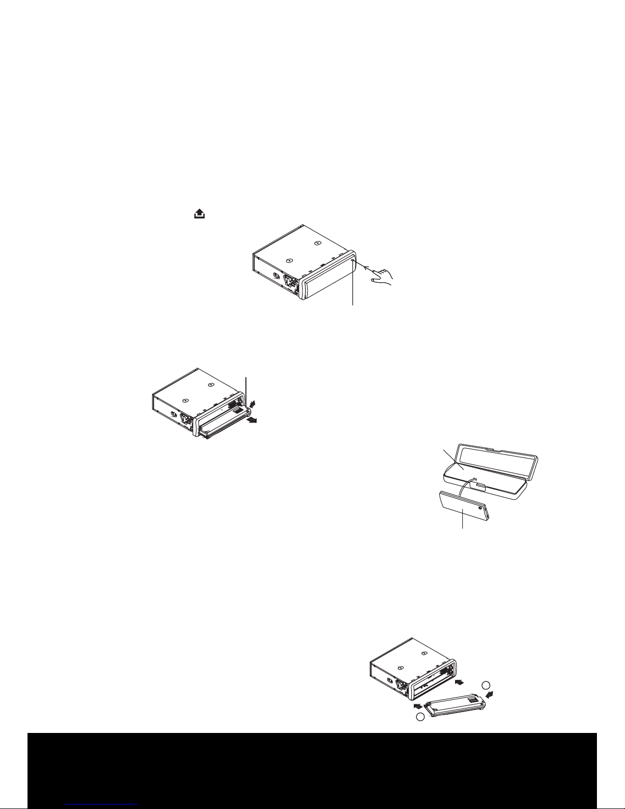
Removing and protecting the detachable front panel
The front panel of the unit may be removed as a theft deterrent. After
removing the front panel, use the case provided to keep the front
panel from getting damaged.
1 Press the OPEN button to ip down the front panel.
2 Grasp the right side of the front panel, then gently push the front panel
towards the left side before pulling it out from the unit.
3 Store the front panel in the protective
case provided for safe keeping.
To attach the front panel
Hold the right side of the front panel with the plate facing down.
First attach the left side of the front panel to the unit by inserting the
hole into the left holder.
Then slightly push it leftward and attach the right side hole into the
right holder. Finally push up the front panel.
Open button
front panel
front panel
protective case
1
2
Using The Detachable Front Panel
Page 9
After Sales Support TEL: 1300 886 649
8
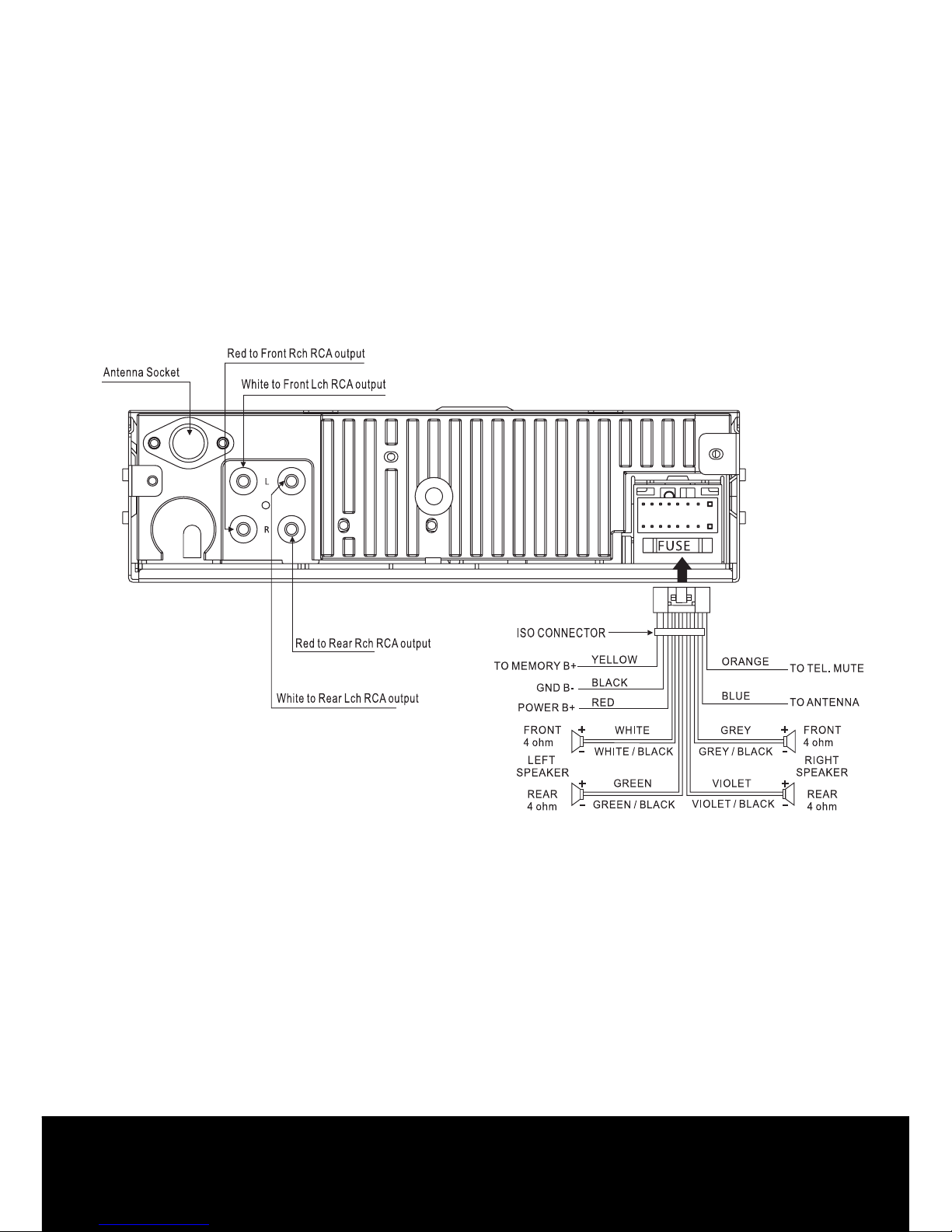
Wiring Diagram
Page 10
After Sales Support TEL: 1300 886 649
9
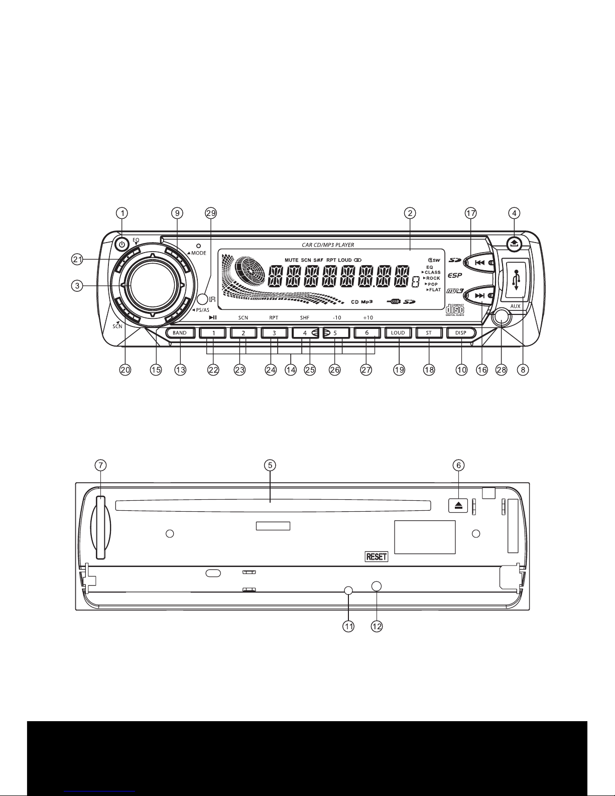
Location and function of the keys
Front panel:
Operations
The front facet after removing the front panel:
Page 11

After Sales Support TEL: 1300 886 649
10
Descriptions of function controls:
1 Power( )/ Mute Button
2 LCD display
3 Encoder Volume Control/ SEL Button
4 Open ( ) Button
5 Disc slot
6 Eject ( ) key
7 SD/MMC Memory Card Slot
8 USB Port
9 MODE Button
10 DISP Button
11 Anti-theft LED Indicator
12 Reset Button
13 Band/ ID3 Button
14 Preset Station (M1-M6) Buttons
15 PS/AS(Preset memory / Scan Auto-storage)
16 UP ( ) Button
Tune up, Seek up, track up, fast forward
17 DOWN ( ) Button
Tune down, Seek down, track down, fast reverse
18 ST Button
19 LOUD(Loudness) Button
20 Scan Button
21 EQ Button
22 Playing/Pausing( ) Button
23 Scan(SCN) Playback Button
24 Repeat(RPT) Playback Button
25 Shue(SHF) Playback Button
26 Skip 10 tracks(-10) Down Button
27 Skip 10 tracks(+10) Up Button
28 AUX Input Jack
29 IR Remote Control Sensor
Page 12
After Sales Support TEL: 1300 886 649
11
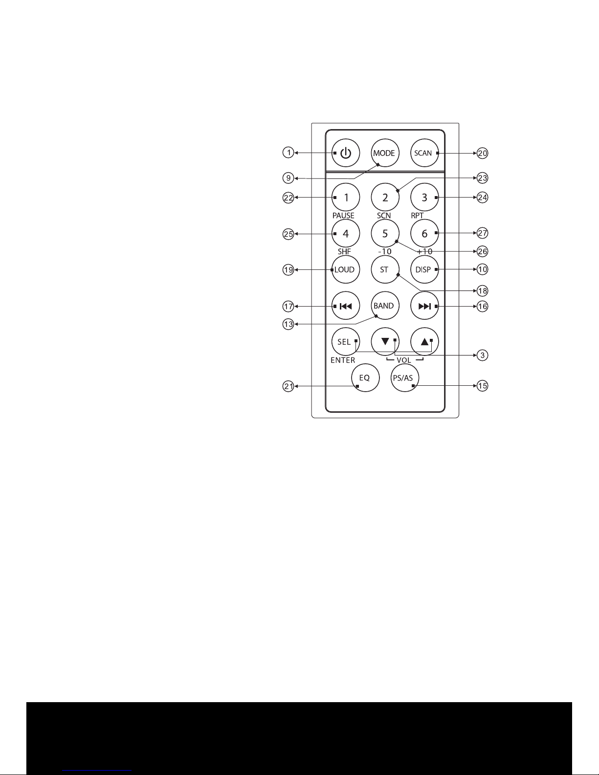
Using the remote control:
Remark:
* Before using the remote control, please take the transparent
insulator slice o the bottom of remote control.
* Point the remote control at the remote sensor within 2 metres.
* It may not be possible to operate the remote control if the remote
control sensor is exposed to direct sunlight.
* Operation angle: about ±30°in each the direction of the front of the
remote sensor.
* The remote control is a small, lightweight precision device.
To avoid damage, short battery life, operational errors and poor
response, observe the following.
- Do not subject the remote control to excessive shock.
- Do not put in a trouser pocket.
- Keep away from food, moisture and dirt.
- Do not place in direct sunshine.
NOTE: Refer to page 10
for key reference.
Page 13
After Sales Support TEL: 1300 886 649
12
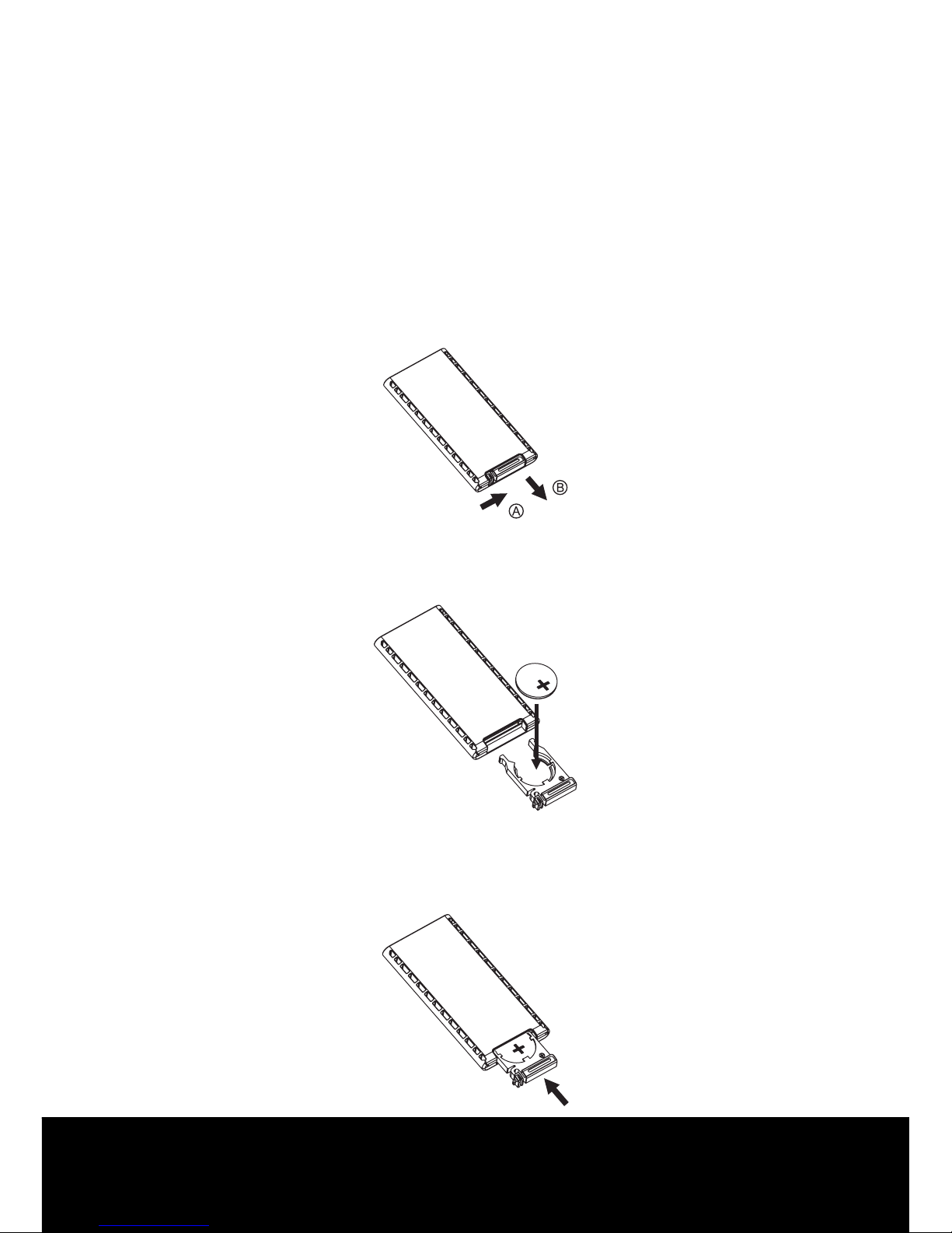
Battery replacement:
Battery type: a button cell lithium battery (CR2025 3V)
1. Remove the battery holder by pressing the locking tab with your
thumb and pulling it out.
2. Replacing the battery:
Replace the battery with the same type and the (+) side facing up.
3. Closing the cover:
Gently push in the holder until it is securely locked into place.
Page 14

After Sales Support TEL: 1300 886 649
13
Reset the unit:
Operating the unit for the rst time, after replacing the car battery or
changing the connections, you must reset the unit.
1. Turn o the unit power.
2. Press the OPEN ( ) button and remove the front panel, then press
the RESET button with a ballpoint pen to restore the unit to the
original factory settings.
Reset the unit:
In power o mode, switch on the unit by pressing any button except
the OPEN button and the EJECT ( ) button or inserting a disc into
the disc slot. When the system is on, press and hold the POWER ( )
button for several seconds to turn o the unit.
Sound Adjustment:
- Rotate the rotary encoder to adjust volume level.
- Press the SEL button once and/or repeatedly to select the following
sound modes:
Volume, bass, treble, balance and fader.
Press the VOL+ or VOL - button to adjust level of
the selected sound mode:
- VOL: Min,01,02 ~ 44,45,Max
- BAS / TRE: -6, -5 ~,0, ~ +5,+6,
- BAL: 6L,5L, ~,0, ~, 5R, 6R
- FAD: 6R, 5R, ~, 0, ~, 5F, 6F
NOTE: In each mode, when the mode has not been adjusted for 3
seconds, display mode returns to normal radio, DISC, SD/MMC
card, USB or AUX mode.
General operation
Page 15

After Sales Support TEL: 1300 886 649
14
System menu:
Press the SEL button and hold for more than 2 seconds to access the
system menu mode, then press the SEL momentarily to select the
menu items in series and circulation as follow:
SEEK PRI/STEP RPI DX/LOCAL LOUD ON/OFF VOL LAST/ADJ
P-VOL BEEP ON/OFF.
After selecting the desired menu item, rotate the rotary encoder to
select the mode of the selected item.
SEEK PRI / STEP PRI:
After entering this mode, rotate the rotary encoder to select the SEEK
PRI or STEP PRI.
- SEEK PRI: If you select this mode , the automatic search will be prior
when you briey press the or button.
- STEP PRI: If you select this mode, the manual search will be prior when
you briey press the or button.
STEREO / MONO:
FM listening is received in stereo mode. However, if the signal is weak
or the reception is not as good as you would like, switching to MONO
mode usually improves the overall sound quality.
Rotate the rotary encoder to choose FM STEREO or MONO audio
eect.
LOCAL / DX:
In urban settings, most stations are strong enough and it should
be set in local mode. However, if a station has weaker signals, try
switching to distant(DX) mode. After entering this mode, rotate the
rotary encoder to local reception mode.
Page 16

After Sales Support TEL: 1300 886 649
15
LOUD ON / OFF:
This function is used to enhance the intensity of bass, after entering
this mode,rotate the rotary encoder to choose loudness on or o.
VOL LAST/ADJUST:
Rotate the rotary encoder to choose between VOL LAST and VOL ADJ.
- VOL LAST: The unit switches on at the last volume level when it was
last switched o.
- VOL ADJ: This function allows you to set the switch-on volume level,
regardless of what level the volume was set at when the
unit was switched o.
PVOL:
To set the volume to a certain level, press the SEL button momentarily
until “PVOL” is shown on the LCD display. Then rotate the rotary
encoder to adjust to a certain volume level.
BEEP ON / OFF:
The car audio device is equipped with 2 beep tone on, beep tone o
function. After entering this mode by pressing the button, rotate the
rotary encoder to choose one.
- Beep on mode: The conrmation beep is heard whenever
a button is pressed.
- Beep o mode: The conrmation beep is switched o when
a key is pressed.
MUTE ON / OFF:
In power on mode, press the POWER ( )/ MUTE button briey to
toggle mute on or o. The muted state will also be released when the
rotary encoder, MODE button is used.
Page 17

After Sales Support TEL: 1300 886 649
16
LOUD ON / OFF:
Press the LOUD button to enhance the intensity of bass. Press again to
cancel the loudness eect.
To select EQ mode:
The car audio device is equipped with 4 preset equalization modes.
Press the EQ button repeatedly to select the EQ modes as follow: DSP
OFF CLASSIC ROCK POP FLAT .
To select playback mode:
In power on mode, press the MODE button repeatedly to select the
dierent modes as the following sequence: TUNER, DISC (with a CD/
MP3 disc inside the disc slot), USB, SD/MMC memory card, AUX mode.
To select the audio auxiliary input mode:
During TUNER, DISC, USB or SD/MMC memory card playback mode,
press the AUX button to switch to audio auxiliary input mode. Press
again to exit and resume original playback mode.
Last position memory feature:
- During disc, USB, SD/MMC card playback, if you turn o the unit and
then switch it on, the unit will resume playing from the point that it
was interrupted.
-During disc, USB, SD/MMC card playback, if you switch to other
modes, and then return to the previous mode again, the unit will
resume playing from the point that it was interrupted.
Page 18

After Sales Support TEL: 1300 886 649
17
Clock display and adjustment:
To view the current time, press the DISP button briey, it will be
shown for about 5 seconds and then revert to the previous display
mode unless the DISP button is pressed again. During the period
when the time is shown on the LCD display, you can adjust the clock
time, press and hold the DISP button, the hour will twinkle, rotate the
rotary encoder on the head unit or press the VOL UP or VOL DOWN
button to adjust hour. Then press the DISP button, the minute will
twinkle, then you can adjust minute by rotating the rotary encoder or
pressing the VOL UP or VOL DOWN button.
TEL MUTE:
The audio system automatically mutes whenever a call comes in.
NOTE: The function will not work if a cable is not connected
to the car phone.
1. When a call is received, ‘TEL CALL’ is displayed and all the unit
functions are temporarily interrupted.
2. Hang up the phone the ‘TEL CALL’ disappears from the display.
The original source is returned to automatically and the volume
restored gradually.
ESP Function:
This unit has the electronic shockproof function. it can be shockproof
for several seconds:
CD: 40 seconds.
MP3/WMA:120 seconds.
Anti-theft LED Indicator:
Designed as a theft deterrent, the red LED will ash when the unit is
turned o and the face plate is removed.
Page 19

After Sales Support TEL: 1300 886 649
18
To select a radio band:
In tuner mode, press the BAND button repeatedly to select a radio
broadcasting band you would like to hear. The FM band is toggled
cyclically through the tuning bands: ->FM 1-> FM 2 -> FM 3 ->MW 1
-> MW 2.
Auto / Manual tuning:
1. When you select the SEEK PRI in the system setup menu:
- Automatic search mode:
Briey press the or button, the auto search will start. It will
search upward or downward for the strongest signal radio stations
within the current band. During auto tuning press the or
button to stop tuning. Pressing and holding the or button for
about 2 seconds until “MANUMODE” appears on LCD display, it will
change into manual search mode.
- Manual search mode:
Press the or button once and/or repeatedly to manually search
upward or downward step by step for the desired radio station within
the current band. In manual search process, if both buttons haven’t
been pressed within 5 seconds, it will change into automatic search
mode automatically, “SEEK MODE” will be visible on the LCD display.
2. When you select the STEP PRI in the system setup menu:
Press the or button to manually search upward or downward
step by step for the desired radio station within the current band.
Press and hold the or button and the auto search will start.
It will search upward or downward for the strongest signal radio
stations within the current band. During auto tuning press the or
button to stop tuning.
Radio Operations
Page 20

After Sales Support TEL: 1300 886 649
19
To store / recall a preset radio stations:
You can store up to a total of 18 FM and 12 MW radio stations in the
memory, manually or automatically.
To store a station:
- Select a band (if needed).
- Select a station by pressing the or buttons.
- Hold a preset button (M1~M6) which you want to store the station
for at least 2 seconds, the current station will be saved into the
relevant preset memory bank.
To recall a station:
- Select a band (if need).
- Press a preset button (M1-M6) briey to recall the stored station.
Auto store / Preset scan:
- Preset scan:
Short pressing the PS / AS button, it scans each preset stations in the
memories of the current band. Each preset station will blink for 5 seconds
with releasing mute, then go to next station, nally the radio will go to
play the start preset station. Press again to stop preset scanning.
- Auto store:
Pressing the PS / AS button for more than 2 seconds, it will enter auto
store mode. The whole band is scanned and the six strongest stations
are stored into the preset memories, after scanning is nished.
Scan function:
Press the SCAN button briey, the tuner starts scanning. When the
tuner detects a good station, it pauses for about 5 seconds after that
continues to scan. Press any function key to stop the scanning.
Page 21
After Sales Support TEL: 1300 886 649
20
Loading/Removing a Disc:
1. Turn the power on.
2. Press the OPEN ( ) button on the front panel ip down the front
panel then insert a disc into the disc slot with the printed side facing
upward; the player will play the disc automatically.
3. Press the EJECT ( ) button to eject the disc at any time.
Playing / Pausing:
- In the track or le playback, press the PLAY/PAUSE (
) button to
interrupt the playback. Press again to resume the playback.
- In the track or le playback, press and hold the PLAY/PAUSE ( )
button for 2 seconds to resume play at the beginning of the rst
track of current disc.
Playing the previous / next track:
- When playing the track or le, briey press the button to play the
next track.
- In playback process, briey press the button once to play
the current track from the beginning. Press the button twice
continuously to play the previous track.
Playing forward and backward:
In the track or le playback, pressing and holding the or button
to fast forward or fast reverse. Release the buttons when the desired
location is found, and normal playing starts.
Playing the +/- 10 track/le up or down:
-In the MP3/WMA playback, briey press the M5 (-10), M6 (+10)
button to play the +/- 10 track down or up.
-In the MP3/WMA playback, press and hold theM5 (-10), M6 (+10)
button to play the tracks or les in the previous or next folder.
CD/MP3 Operations
Page 22

After Sales Support TEL: 1300 886 649
21
Scanning playback:
You can play the beginning of each track or le for 10 seconds in
sequence.
- In the CD/MP3/WMA le playback, briey press the M2 (SCAN)
button to play the rst 10 seconds of each track.
Press again to stop scanning and play the current track.
- For MP3/WMA les, press and hold the M2 (SCAN) button to play the
rst 10 seconds of each track in the current folder. Press again to stop
scanning and play the current track.
Repeat playback:
- In CD/MP3/WMA les playback, briey press the RPT button to
continuously play the current track. Press again to stop repeat
playback and resume normal playback.
- For MP3/WMA les, press and hold the RPT button to play all the
tracks in the current folder. Press again to stop repeat and resume
normal playback.
Shue playback:
- In CD/MP3/WMA les playback, briey press the SHF button to play
all tracks of the disc or USB device, SD/MMC memory card in random
sequence. Press again to cancel random playing.
- For MP3/WMA les, press and hold the SHF button to randomly play
all the tracks in the current folder.
Page 23

After Sales Support TEL: 1300 886 649
22
Select the track or le for playback in MP3 or WMA format:
You can access 4 dierent types of track search modes for MP3/WMA
format:
Track search --> le name search --> ROOT directory search -->
Current directory search --> Exit.
Serial number of track search mode:
a) In playback of discs with MP3 or WMA format, press the PS/AS
button once to access the track number search mode which allow
you to quickly nd a specic MP3/WMA track by its serial number,
and the total amount of MP3/WMA tracks in the current disc, USB
device or SD/MMC memory card ( e.g: TRK 093 )will appear on the
LCD display, and the rst digit will blink.
b) Rotate the rotary encoder to adjust the rst digit.
c) If you press and hold the SEL button, the system will play the
selected track. If you press the SEL button briey to conrm, and the
second digit will blink, and you can select and enter the second digit
by rotating the rotary encoder.
d) If you press and hold the SEL button, the system will play the
selected track. If you press the SEL button briey to conrm, the
third digit will blink, and you can select and enter the third digit by
rotating the rotary encoder. Finally press the button, and the system
will nd and play the selected track.
Page 24

After Sales Support TEL: 1300 886 649
23
The track name search mode:
The track name search will allow you to quickly nd an MP3/WMA
title by name.
a) To access this feature, press the PS/AS button twice, the “A” will be
shown and blink on the LCD display.
b) Change the blinking character by rotating the rotary encoder.
The character will be changed from “A” through “Z” , and from “0”
through “9” and from ,blank space , , , , , , .
Press the SEL button to conrm the character entered and advance
to the next character. If a character is wrongly input, press the
BAND button to delete the incorrect one.
c) After you have put in the name, press and hold the SEL button,
the system will search the relevant song. The song nearest
alphabetically to the name input will be found and then begin to
play. If the le was not found, “NO FILE” message will be visible on
the display.
Root directory search mode:
The root directory search mode will allow you to quickly nd an MP3/
WMA title under a specic group folder.
a) In playback of discs with MP3 or WMA format, press the PS/AS
button three times to access the rst folder mode.
b) Rotate the rotary encoder to change and select a desired folder (If
there are no root Folder in the disc, the LCD will display “ROOT”).
c) Once the folder has been selected by pressing the SEL button, then
rotate the rotary encoder to browse the tracks or les.
d) Finally press the SEL button to conrm and play the the track or le
of the selected folder.
Current directory search mode:
a) In playback of discs with MP3 or WMA format, press the SEL button
four times to access to current directory search mode.
b ) Rotate the rotary encoder to browse the tracks or les in the
current directory.
c) Press the SEL button to conrm and play the selected le or track.
Page 25

After Sales Support TEL: 1300 886 649
24
d) If the selected title is a subdirectory, rotate the rotary encoder to
browse all the les in the subdirectory, then press the SEL button
to conrm and play a selected le or track.
ID3 information of MP3 le:
In playback of discs with MP3 format, press the BAND button, the
folder name, le name, title, artist and album information will be
scrolling on the LCD display automatically.
NOTE: As long as the current playing MP3 music contains relevant
ID3 tag information in version 1.0/2.0 format, the 3 items
underlined above will be scrolling on the LCD display,
otherwise, they will not appear.
Mixed Mode CD operations
If available, the unit can play the mixed mode CD disc (the disc
contains both CD audio tracks and MP3 les).
Under a default mode, the unit will rst play all the MP3 formatted
songs and then play the CD formatted songs.
Page 26

After Sales Support TEL: 1300 886 649
25
SD/MMC Memory Card Operations
AUX IN Operations
This unit is equipped with a memory card slot.
Using the SD/MMC card:
When you insert a SD/MMC card into the memory card slot, the player
will read the SD/MMC card automatically. The unit gives rst priority
to the latter. If inserting a disc into the disc slot while reading the SD/
MMC card, the unit will play the disc. You can press the SEL button to
select SD/MMC mode.
SD/MMC memory card playing operation is the same with the MP3
operation described above.
NOTE:
- The operations of the MP3 le in the SD/MMC memory card is the
same as the MP3 operation described in the MP3/WMA disc part.
- When reading the memory card, please don’t touch or take out the
card.
- If following the instruction above, the unit can’t read the card, please
check if the card is in good condition, or take out the card then
insert it into the card slot once more.
This system has an external input jack, so you can listen to sounds and
music from external devices connected to this unit. Press the MODE
button to switch to the mode.
WARNING: The manufacturer is not responsible for any data loss
from a SD/MMC card even if the data loss has occured
while using the car stereo.
Page 27

After Sales Support TEL: 1300 886 649
26
USB Device Operations
The unit is equipped with a USB port on the front panel of the unit,
you can connect a USB stick through the USB port.
Using the USB stick:
When you insert a USB stick through the port, the unit will search the
MP3 les and start to play it automatically. The unit gives priority to
the latter. If you insert a disc into the disc slot while it is reading the
SD/MMC card, the unit will play the disc. You can press the MODE
button to select USB mode.
NOTES:
- The operations of the MP3 le in the USB is the same as the MP3
operation described in the MP3/WMA disc part.
- When reading the USB stick, please don’t touch or take it out.
- If following the instructions above, the unit can’t read the le in the
USB stick, please check if the device is in good condition, or take it
out then insert it into the USB port once more.
- The main unit can only support the standard USB-memory disc.
- USB MP3 player is not a standard which means dierent brand name
or dierent models have their own standard. So our product cannot
support all MP3 players.
- When connecting an MP3 player that has a normal battery in the
player (non rechargeable battery), you should remove the battery
from the MP3 player then connect it to the USB port. Otherwise, it
may cause battery damage.
- When in USB play mode, be sure not to remove the USB device from
the USB port.
WARNING: The manufacturer is not responsible for any data loss
from a USB device even if the data loss has occured
while using the car stereo.
Page 28
After Sales Support TEL: 1300 886 649
27
Disc Notes
A. Notes on discs:
1. Attempting to use non-standard shape discs (e.g. square, start, and
heart) may damage the unit. Be sure to use round shape CD discs
only for this unit.
2. Do not stick paper or tape, etc, onto the label side or the recording
side of any discs, as it may cause a malfunction. Dirt, dust, scratches
and warping discs will cause malfunction.
B. Notes on CD-Rs (recordable CDs/CD-RWs re-writable CDs):
1. Be sure to use discs with following marks only for the unit to play:
2. The unit cannot play a CD-R and CDRW that is not nalised. (Please
refer to the manual of your CD-R/CD-RW recorder or CD-R/CD-RW
software for more information on nalisation process).
3. Depending on the recording status, conditions of the disc and the
equipment used for the recording, some CD-Rs/CDRWs may not be
played on this unit. (see *1).
*1: To have more reliable play back, please see following
recommendations:
a. Use CD-RWs with speed 1x to 4x and write with speed 1x to 2x.
b. Use CD-Rs with speed 1x to 8x and write with speed 1x to 2x.
c. Do not play a CD-RW which has been written to more than 5 times.
C. Notes on MP3 les:
The disc must be in the ISO9660 level 1 or level 2 format, or Juliet or
Romeo in the expansion format.
1. When naming a MP3 le, be sure the le name extension is ‘MP3’.
2. For a non-MP3 le, even though the le name extension is ‘MP3’,
the unit cannot recognise it.
Recordable ReWritable
Page 29

After Sales Support TEL: 1300 886 649
28
D. Handling and cleaning:
- Dirt, dust, scratches and warping discs will cause malfunction.
- Do not place stickers or make scratches on discs.
- Do not warp discs.
- A disc should always be kept in its case when not in use to
prevent damage.
- Do not place discs in the following places:
1. Direct sunlight.
2. Dirty, dusty and damp areas.
3. Near car heaters.
4. On the seats or dashboard.
Disc cleaning:
Use a dry soft cloth to wipe the surface. If the disc is quite dirty, use a
soft, lightly dampened cloth with isopropyl (rubbing) alcohol. Never
use solvents such as benzene, thinner or conventional record cleaners
as they may mark the surface of the disc.
NOTE: A disc may become somewhat scratched (although not enough
to make it unusable) depending on the way it is handled and
conditions in the usage environment. Note these scratches are
not an indication of any problem with the player.
Page 30

After Sales Support TEL: 1300 886 649
29
E. Preparing new discs with rough spots:
A new disc may have rough edges on its inside and outside edges.
If a disc with rough edges is used, the proper setting will not be
performed and the player will not play the disc. Therefore, remove the
rough edges in advance by using a ballpoint pen or pencil as shown
below To remove the rough edges, press the side of the pen or pencil
against the inside and outside edges of the disc.
Page 31

After Sales Support TEL: 1300 886 649
30
1. GENERAL
Power Supply Requirements
DC 12 Volts, Negative Ground
Chassis Dimensions
178 mm (W) x 160 mm (D)x 50 mm (H)
Tone Controls
- Bass (at 100 Hz) ±10 dB
- Treble (at 10 KHz) ±10 dB
Maximum Output Power
4 x 50 watts
Current Drain
15 Ampere (max.)
2. CD PLAYER
Signal to Noise Ratio
> 55 dB
Channel Separation
> 40 dB
Frequency Response
40Hz - 18 KHz
3. RADIO
FM
Frequency Coverage
87.5 - 108.0 MHz
IF: 10.7 MHz
Sensitivity (S/N=30dB)
4μV
AM
Frequency Coverage:
531 - 1629 KHz
IF: 450 KHz
Specications
Page 32

After Sales Support TEL: 1300 886 649
31
• This appliance is not intended for use by young children or
inrm persons unless they have been adequately supervised by a
responsible person to ensure that they can use the car stereo safely.
• Young children should be supervised to ensure they do not play
with the car stereo.
• Do not insert anything other than a CD into the CD loading slot.
• Do not allow this unit to come in contact with liquids. Electrical
shock could result. Also, damage to this unit, smoke, and over
heating could result from contact with liquids.
• Keep this manual handy as a reference for operating procedures and
precautions.
• Always keep the volume low enough so that you can hear sounds
from outside the vehicle.
• Protect the unit from moisture.
• If the battery is disconnected or discharged, the preset memory will
be erased and must be reprogrammed.
• This unit must be installed by a professional technician only or the
warranty will be void.
Important notes
Page 33

After Sales Support TEL: 1300 886 649
32
Symptom Cause Solution
No power
The car ignition is not
turned on.
If the power supply
is connected to the
car accessory circuits,
but the engine is not
moving, switch the
ignition key to “ACC”
The fuse has blown. Replace with a new
one.
Disc can not be loaded
or ejected
Presence of CD disc
inside the player.
Remove the disc from
the player, and insert a
new one
.
Inserting the disc in
reverse direction.
Insert the CD with the
label facing upwards.
The surface of CD is
extremely dirty or has
been scraped.
Clean the disc or try to
replace with a new one.
Temperature inside the
car is too high.
Cool o or until the
ambient temperature
returns to normal.
Condensation Leave the player o for
an hour or so, and then
try again.
The following chart will help in solving most problems that may
occur. If you still have questions after going through the checklist,
please consult your local customer service representative. Before
going through this check list, refer to the wiring and operating
procedures.
FAQ’s
Page 34

After Sales Support TEL: 1300 886 649
33
No sound Volume is on minimum. Adjust volume to a
desired level.
The wiring is not
properly
connected.
Check the wiring
connection.
Sound skips The installation angle is
more than 30°
..
Adjust the installation
angle to less than 30°.
The surface of CD is
extremely dirty or has
been scraped.
Clean the disc or try to
replace with a new one.
The operation keys
do not work
1. The built-in
microcomputer is not
operating properly due
to noise.
1. Press the RESET
button to restore the
program.
2. The front panel is not
properly installed.
2. Fix the front panel
into its place.
No radio reception The antenna cable is
not connected.
Insert the antenna
cable rmly into
the antenna socket of
this CD player.
In automatic search
mode the radio
does not stop at a
transmitting station.
The transmission
signals are too weak.
Select a radio station
manually.
Page 35

After Sales Support TEL: 1300 886 649
34
(This page has been left intentionally blank)
Page 36

After Sales Support TEL: 1300 886 649
 Loading...