

Page 1

SYSTEM-30 BTU MEASUREMENT SYSTEM
LON Version
Installation and Operation Guide
0668-2 / 18337
For Software Version DD3.3S30 or higher.
11451 Belcher Road South, Largo, FL 33773 • USA • Tel +1 (727) 447-6140 • Fax (727)442-5699
www.onicon.com • sales@onicon.com
05-14
Page 2
SAFETY INFORMATION
!
!
i
This meter was calibrated at the factory before shipment.
To ensure correct use of the meter, please read this manual thoroughly.
Regarding This Manual:
• This manual should be passed on to the end user.
• Before use, read this manual thoroughly to comprehend its contents.
• The contents of this manual may be changed without prior notice.
• All rights reserved. No part of this manual may be reproduced in any form without
ONICON’s written permission.
• ONICON makes no warranty of any kind with regard to this material, including, but
not limited to, implied warranties of merchantability and suitability for a particular
purpose.
• All reasonable effort has been made to ensure the accuracy of the contents of this
manual. However, if any errors are found, please inform ONICON.
• ONICON assumes no responsibilities for this product except as stated in the warranty.
• If the customer or any third party is harmed by the use of this product, ONICON
assumes no responsibility for any such harm owing to any defects in the product which
were not predictable, or for any indirect damages.
Safety Precautions:
The following general safety precautions must be observed during all phases of
installation, operation, service, and repair of this product. Failure to comply with these
precautions or with specic WARNINGS given elsewhere in this manual violates safety
standards of design, manufacture, and intended use of the product. ONICON Incorporated
assumes no liability for the customer’s failure to comply with these requirements. If this
product is used in a manner not specied in this manual, the protection provided by this
product may be impaired.
The following symbols are used in this manual:
Messages identied as “Warning” contain information regarding the personal safety of
individuals involved in the installation, operation or service of this product.
Messages identied as “Caution” contain information regarding potential damage to the
product or other ancillary products.
Messages identied as “Important Note” contain information critical to the proper operation
of the product.
WARNING
CAUTION
IMPORTANT NOTE
1 1451 Belcher Road South, Largo, FL 33773 • USA • Tel +1 (727) 447-6140 • Fax (727) 442-5699 • sales@onicon.com
System-30 BTU Measurement System LON 05/14 - 0668-2 / 18337 Page 2
Page 3

TABLE OF CONTENTS
1.0 INTRODUCTION .............................................................................................................. 5
1.1 Purpose of this Guide ............................................................................................... 5
1.2 Typical SYSTEM-30 BTU MEASUREMENT SYSTEM ........................................... 5
1.3 Standard Features and Specications ..................................................................... 6
1.4 Working Environment .............................................................................................. 7
1.5 Warranty and Serial Number ................................................................................... 7
2.0 UNPACKING ..................................................................................................................... 8
2.1 Checking That You Have Received Everything ...................................................... 8
3.0 INSTALLATION ................................................................................................................ 9
3.1 Site Selection ............................................................................................................ 9
3.2 Mechanical Installation ......................................................................................... 10
3.2.1 Main Unit Installation .................................................................................. 10
3.2.2 Thermowell Installation .............................................................................. 11
3.2.3 Temperature Sensor Installation ................................................................. 11
3.3 Electrical Installation ............................................................................................. 13
3.3.1 Single Mode vs. Dual Mode Operation ....................................................... 13
3.3.2 Electrical Wiring .......................................................................................... 16
4.0 START UP & COMMISSIONING ..................................................................................... 17
4.1 Display and User Interface ....................................................................................... 17
4.2 Processor Start Up ................................................................................................... 17
4.3 Units and Multipliers ............................................................................................... 18
4.4 LonWorks Network Addressing ............................................................................... 19
4.4.1 LonWorks Network Addressing ................................................................... 19
4.5 Commissioning the System-30-LON ....................................................................... 19
4.5.1 Service Pin LED States ................................................................................... 19
4.6 LonWorks XIF Files ................................................................................................. 19
4.6.1 Output Network Variables ........................................................................... 19
4.6.2 Integer Format Output Network Variables .................................................. 20
4.6.3 Input Network Varables ............................................................................... 21
4.6.4 Node Object Network Variables ................................................................... 21
4.6.4.1 nviRequest ...................................................................................... 21
4.6.4.2 nvoStatus ........................................................................................ 22
4.6.5 Resetting Totals Via the Network ................................................................. 22
4.6.6 Rollover of Totals.......................................................................................... 23
4.7 Diagnostics ............................................................................................................. 24
4.7.1 Diagnostic Lights .......................................................................................... 24
4.8 Commissioning ........................................................................................................ 25
4.8.1 Commissioning Worksheet .......................................................................... 26
1 1451 Belcher Road South, Largo, FL 33773 • USA • Tel +1 (727) 447-6140 • Fax (727) 442-5699 • sales@onicon.com
System-30 BTU Measurement System LON 05/14 - 0668-2 / 18337 Page 3
Page 4

APPENDIX A – DRAWINGS
A-1 TYPICAL SYSTEM INSTALLATION
A-2/A-3 THERMOWELL INSTALLATION
A-4 WIRING DIAGRAM AND SIGNAL CONNECTION BOARD
A-5 WIRING DIAGRAM FOR DIN CONNECTOR
A-6 LON BOARD
A-7 LONWORKS TWISTED PAIR NETWORK TERMINATION
A-8/A-9 INTEGER FORMAT OUTPUT NETWORK VARIABLES
A-10 CONDITIONS OF SALE
1 1451 Belcher Road South, Largo, FL 33773 • USA • Tel +1 (727) 447-6140 • Fax (727) 442-5699 • sales@onicon.com
System-30 BTU Measurement System LON 05/14 - 0668-2 / 18337 Page 4
Page 5
SECTION 1.0: INTRODUCTION
!
SYSTEM-30 BTU MEASUREMENT SYSTEM WITH INTEGRAL
FLOW METER & TEMPERATURE SENSORS
INCORPORATED
WARNING
Only qualied service personnel should attempt to install or service this equipment. Serious
injury may result from the improper installation or use of this equipment.
1.1 PURPOSE OF THIS GUIDE
The purpose of this guide is to provide installation and commissioning procedures and basic
operating and servicing instructions for the ONICON SYSTEM-30 BTU MEASUREMENT
SYSTEM.
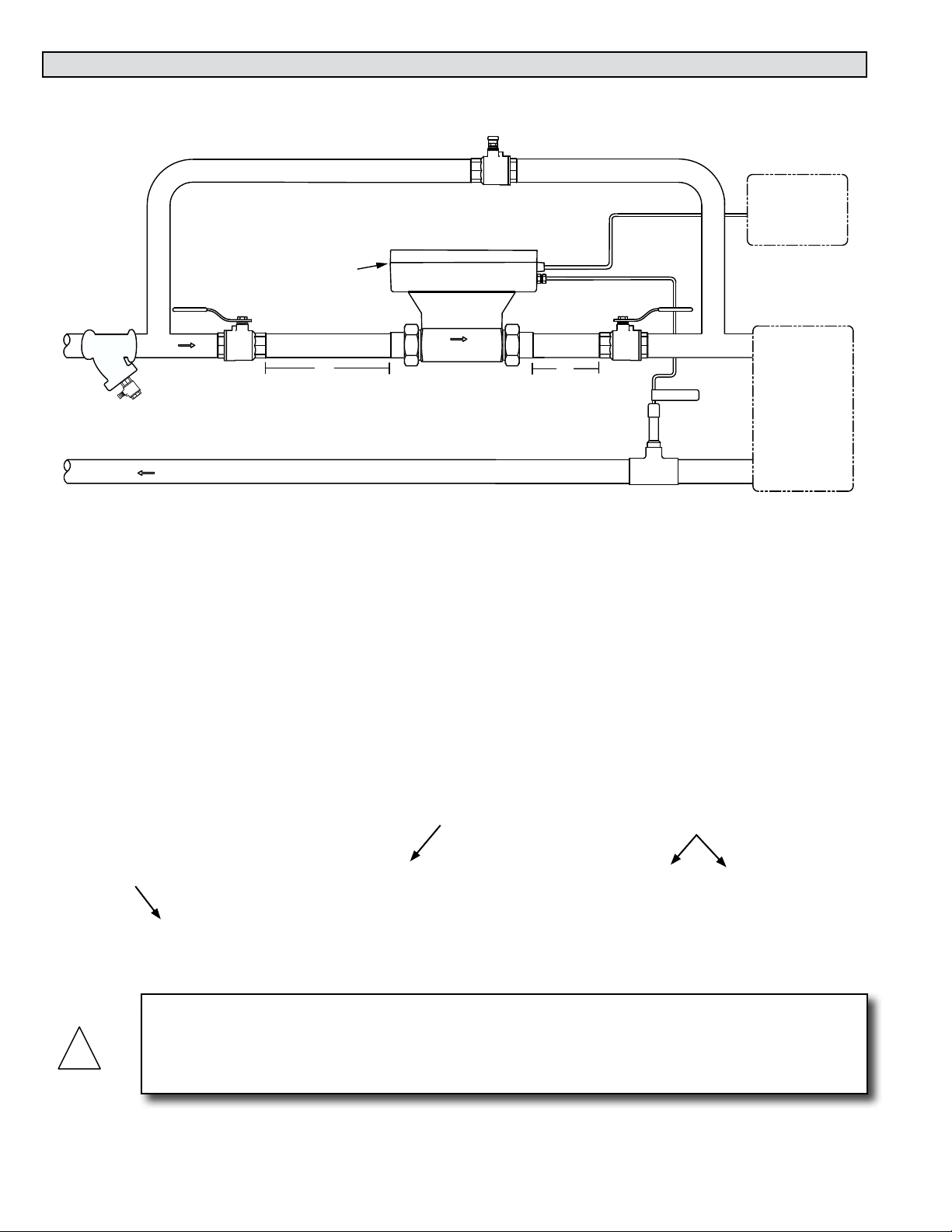
1.2 TYPICAL SYSTEM-30 BTU MEASUREMENT SYSTEM
ONICON’S System-30 is a true heat (Btu) computer, which accepts data from several sensors,
performs a series of computations with that data, and transmits the results as an indication of the
amount of heat (Btu’s) being transferred or as a totalized amount.
Y Strainer Upstream
Of Flow Meter
CHILLED WATER
RETURN
BYPASS VALVE
Normally Closed
DIAGNOSTIC
20"
LED’S
ISOLATION VALVE
FLOW
5"
ISOLATION VALVE
Normally Open
CHILLED WATER
SUPPLY
Normally Open
RETURN TEMP
CONTROL SYSTEM
CONTROL SYSTEM
LonTalk
BACnet MS/TP
NETWORK
NETWORK
24V AC/DC
24 VAC POWER
FAN COIL UNIT
OR
AIR HANDLING UNIT
1 1451 Belcher Road South, Largo, FL 33773 • USA • Tel +1 (727) 447-6140 • Fax (727) 442-5699 • sales@onicon.com
System-30 BTU Measurement System LON 05/14 - 0668-2 / 18337 Page 5
Page 6
1.3 STANDARD FEATURES AND SPECIFICATIONS
• Single mode Btu calculations, in either the heating or cooling mode, are totalized and
reported.
• Two-pipe dual mode Btu calculations in both the heating mode and the cooling mode are
totalized and reported separately.
• Auxiliary pulse input for totalizing pulse outputs from external devices such as water or
gas meters.
GENERAL SPECIFICATIONS
CALIBRATION
Flow sensor and temperature sensors are individually
calibrated, followed by a complete system calibration.
Field commissioning is also available.
ACCURACY
Differential temperature accuracy ±0.15° F over
calibrated range
Computing non-linearity within ±0.05%
Flow sensor accuracy:
±0.5% OF READING at calibrated velocity
±1% OF READING from 3 to 30 ft/s (10:1 range)
±2% OF READING from 0.4 to 20 ft/s (50:1 range)
TEMPERATURE SENSORS
Solid state sensors are custom calibrated using N.I.S.T.
traceable temperature standards.
PROGRAMMING
Factory programmed for each specic application
MEMORY
Nonvolatile EEPROM memory retains all program parameters
and totalized values in the event of power loss.
OUTPUT SIGNALS
Isolated solid state dry contacts for mode 1 and mode
2 energy total
Contact rating: 100 mA, 50VDC maximum
Contact duration: 0.5, 1, 2 or 6 sec selectable
NETWORK INTERFACE
LonTalk
2-wire TP/FT-10F transceiver
OUTPUT SIGNALS
LONWORKS® Output Points: (TP/FT-10F)
Variable Description Units SNVT Name
Energy Total Btu SNVT_btu_f
Energy Rate Watts SNVT_power_f
Flow Rate Liters/Sec SNVT_ow_f
Supply Temperature °C SNVT_temp_f
Return Temperature °C SNVT_temp_f
Flow Total Liters SNVT_vol_f
Auxiliary Input No Units SNVT_count_f
BAUD RATE
78 kbps
INPUT SIGNALS
One isolated auxiliary pulse input for totalization
(Factory congurable for active pulse, open collector
sinking, open collector sourcing or dry contact pulses)
3 – 24V dc
50Hz maximum frequency
10msec minimum pulse duration
OPTIONAL LOCAL DISPLAY
Alphanumeric backlit LCD displays total energy, total, flow, energy
rate, flow rate, supply temperature and return temperature
Alpha: 16 characters, 0.2” high
Numeric: 6 digit, 0.4” high
MAINTENANCE
ONICON recommends periodic inspection and recalibration.
No other periodic maintenance is required.
TEMPERATURE RANGE
Liquid temperature range: 32° to 200°F
Ambient temperature range: 40° to 120°F
MECHANICAL
OVERALL DIMENSION:
9.25” L x 5” W x 6.5” H
TEMPERATURE THERMOWELL:
Brass thermowell (½” sweat or ¼” NPT)
ELECTRICAL
This equipment is intended for INSTALLATION
CATEGORY (OVERVOLTAGE CATEGORY) II
applications
INPUT VOLTAGE: 24 V ±10% AC 50/60 Hz or
24 V ±4 DC
INPUT CURRENT: 200 mA maximum
TERMINALS CONNECTIONS: Use 18-22 ga. Copper wire. Do
not exceed 4.5 in-lb (0.5 Nm) of torque when tightening.
WIRING:
CONDUIT: Use PVC jacketed copper cable with a wire Gauge
suitable for the length of run and required maximum current
carrying capacity. The installation must comply with all
local, state and federal codes.
PLENUM AREA: (without conduit) Use plenum rated
copper cable with a wire gauge suitable for the length of
run and required maximum current carrying capacity. The
installation must comply with all local, state and federal
building codes.
Note: Specications are subject to change without notice.
1 1451 Belcher Road South, Largo, FL 33773 • USA • Tel +1 (727) 447-6140 • Fax (727) 442-5699 • sales@onicon.com
System-30 BTU Measurement System LON 05/14 - 0668-2 / 18337 Page 6
Page 7

1.4 WORKING ENVIRONMENT
The SYSTEM-30 was designed for installation and use in typical commercial and residential
environments that are free of corrosive liquids and fumes, direct liquid exposure, heavy
condensation, and temperature extremes and vibrations.
The operating ambient air temperature range is 40° F to 120° F.
The electrical power should be relatively clean, free of high frequency noise, large voltage
transients, and protected from power surges and brown outs.
1.5 WARRANTY & SERIAL NUMBER
Warranty
ONICON’s 2-year “No-fault” warranty reduces start-up costs with extended coverage that
includes coverage for incidental damage during installation. Certain exclusions apply. See
our complete warranty statement for details.
Serial Number
The serial number of your SYSTEM-30 is located on the side of the enclosure. Serial
numbers are unique identiers that you should have available when contacting the factory
for assistance regarding your system.
1 1451 Belcher Road South, Largo, FL 33773 • USA • Tel +1 (727) 447-6140 • Fax (727) 442-5699 • sales@onicon.com
System-30 BTU Measurement System LON 05/14 - 0668-2 / 18337 Page 7
Page 8

SECTION 2.0: UNPACKING
Each SYSTEM-30 generally ships in one package. Inspect all packages immediately upon receipt.
Notify ONICON and the freight carrier if the shipment arrives with evidence of damage in transit.
2.1 CHECKING THAT YOU HAVE RECEIVED EVERYTHING
Standard Documentation
Enclosed with each SYSTEM-30 is a comprehensive documentation package that includes
the following items:
The SYSTEM-30 BTU MEASUREMENT SYSTEM Installation and Operation Guide
The System-30 Calibration Data Sheet
Please notify ONICON immediately if any items are missing.
The Main Unit
Remove the System-30 from the shipping carton and inspect it for physical damage.
Temperature Sensors
One temperature sensor is built-in to the body of the meter and the other is connected to
the main unit via a permanently attached cable. Inspect the free sensor and cable for
external damage.
Temperature Thermowell
A standard thermowell with installation hardware is packed with the main unit.
Mounting Hardware
The System-30 is supplied with two process connections to facilitate connection to the
piping system. A union with retaining nut makes up one end of each end piece. The
other end will either be a sweat tting for copper or a threaded nipple with male NPT
threads.
1 1451 Belcher Road South, Largo, FL 33773 • USA • Tel +1 (727) 447-6140 • Fax (727) 442-5699 • sales@onicon.com
System-30 BTU Measurement System LON 05/14 - 0668-2 / 18337 Page 8
Page 9
SECTION 3.0: INSTALLATION
!
The SYSTEM-30 BTU MEASUREMENT SYSTEM should be installed by experienced plumbers and
others with related knowledge and experience in the heating, cooling, and uid metering elds.
ONICON will be happy to assist with technical recommendations and to provide guidance by
telephone and/or mail. On-site eld engineering, installation, and/or service is also available at an
additional cost.
The installer should use good trade practices and adhere to all state and local building or other
applicable codes.
CAUTION
ONICON strongly recommends the use of a valved bypass and strainer in conjunction with the
installation of the System-30 to facilitate servicing and to protect the turbine assembly during
start-up.
3.1 SITE SELECTION
Careful attention to the site selection for the system components will help the installers with the
initial installation, reduce start-up problems, and make future maintenance easier. For example,
do not install the System-30 or its temperature sensor where it will be difcult for personnel to
perform periodic maintenance and calibration. When selecting a site for mounting the system
components, consider the criteria under Section 1.4, WORKING ENVIRONMENT, as well as the
following:
The Main Unit
Choose the location (supply or return) with the longest straight, unobstructed run. Ideally,
the location chosen should allow for at least 20 diameters of unobstructed straight run
upstream of the meter and at least 5 diameters of unobstructed straight run downstream.
If both the supply and return have adequate straight run conditions, locate the meter in the
supply.
The location must be accessible to facilitate service and recalibration.
The Temperature Sensor
The remote temperature sensor should be located in an accessible location. This will
facilitate any on-site service.
Place the temperature sensor away from sources of electrical noise that might interfere
with the temperature sensor signal.
1 1451 Belcher Road South, Largo, FL 33773 • USA • Tel +1 (727) 447-6140 • Fax (727) 442-5699 • sales@onicon.com
System-30 BTU Measurement System LON 05/14 - 0668-2 / 18337 Page 9
Page 10
3.2 MECHANICAL INSTALLATION
SYSTEM-30 BTU MEASUREMENT SYSTEM WITH INTEGRAL
FLOW METER & TEMPERATURE SENSORS
INCORPORATED
!
3.2.1 Main Unit Installation
BYPASS VALVE
Normally Closed
DIAGNOSTIC
LED’S
Y Strainer Upstream
Of Flow Meter
CHILLED WATER
RETURN
ISOLATION VALVE
CHILLED WATER
SUPPLY
Normally Open
FLOW
20"
ISOLATION VALVE
Normally Open
5"
RETURN TEMP
Installing the meter body
1. Make sure the unions are free of nicks or scratches on either end of the ow
meter body and on the process connections.
2. Spray the union faces with a silicone spray or apply a thin coat of beeswax to enhance
seating. Do not use paste thread sealant on union faces.
3. Orient the ow arrow on the meter with the direction of ow.
4. Recommended torques for union seal: 70 ft/lbs minimum
5. Make sure alignment of pipe does not put lateral stress on either joint.
CONTROL SYSTEM
CONTROL SYSTEM
LonTalk
BACnet MS/TP
NETWORK
NETWORK
24 VAC POWER
24V AC/DC
FAN COIL UNIT
OR
AIR HANDLING UNIT
Process
Connection
Unions
Process
Connection
CAUTION
Before you attempt to use the BTU measurement system, isolate the main unit, open the bypass
and ush the entire system so that it is free of ux, solder, pipe and tube cuttings and any other
free moving particles.
1 1451 Belcher Road South, Largo, FL 33773 • USA • Tel +1 (727) 447-6140 • Fax (727) 442-5699 • sales@onicon.com
System-30 BTU Measurement System LON 05/14 - 0668-2 / 18337 Page 10
Page 11
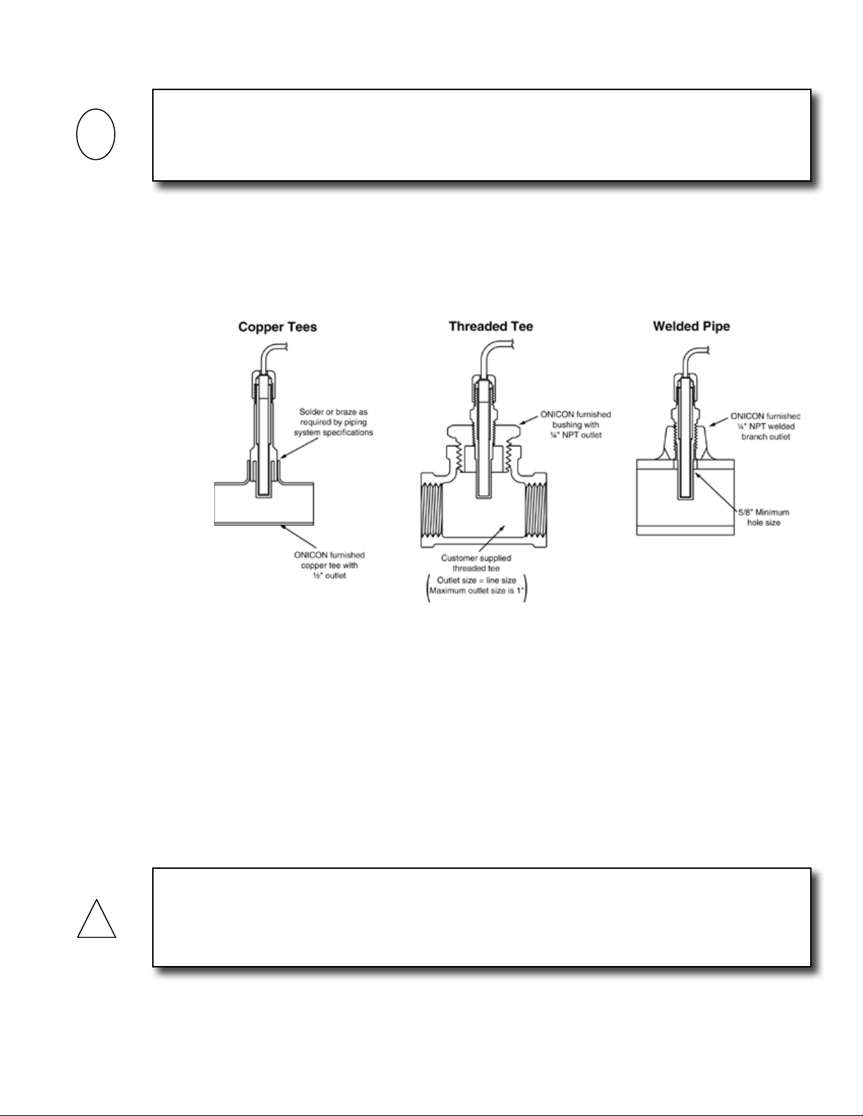
3.2.2 Thermowell Installation
!
i
IMPORTANT NOTE
It is important that no dirt or other foreign material be allowed into the thermowell as this could
affect the thermal response of the system.
Standard Thermowell
The most common installation methods are shown below. Consult the factory for
special applications.
3.2.3 Temperature Sensor Installation
The temperature sensor is factory matched and permanently attached to the BTU
MEASUREMENT SYSTEM. Sensors from different Btu meters cannot be used without
being returned to the factory for recalibration.
Apply a thin coat of thermally conductive grease to the temperature sensor, and gently
insert the temperature sensor all the way into the thermowell until it contacts the bottom
of the cavity. Gently tighten the retainer cap. DO NOT OVER TIGHTEN. The thermowell
completely seals the plumbing system without the retainer cap. The only purpose of the
cap is to keep the sensor from losing contact with the bottom of the thermowell cavity.
CAUTION
Cable length is specied at time of order. This is three wire shielded plenum rated cable.
Altering the cable length will affect calibration. Do not change the cable length without
consulting ONICON.
1 1451 Belcher Road South, Largo, FL 33773 • USA • Tel +1 (727) 447-6140 • Fax (727) 442-5699 • sales@onicon.com
System-30 BTU Measurement System LON 05/14 - 0668-2 / 18337 Page 11
Page 12
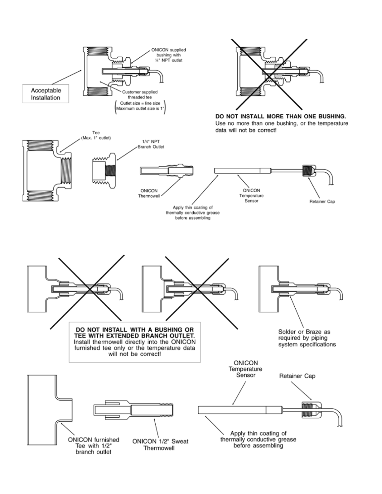
THERMOWELL INSTALLATION IN THREADED PIPE TEES
THERMOWELL INSTALLATION IN COPPER TEE
1 1451 Belcher Road South, Largo, FL 33773 • USA • Tel +1 (727) 447-6140 • Fax (727) 442-5699 • sales@onicon.com
System-30 BTU Measurement System LON 05/14 - 0668-2 / 18337 Page 12
Page 13

THERMOWELL INSTALLATION IN WELDED PIPE
i
3.3 ELECTRICAL INSTALLATION
All user supplied conduit ttings, junction boxes, etc. are to be installed as required by all
applicable building codes.
IMPORTANT NOTE
The System-30-LON BTU Meter is designed with one internal (Temp1) and one remote (Temp 2)
temperature sensor. If the meter body is located in the supply pipe then the internal temperature
sensor will indicate the supply temperature and the remote sensor will indicate the return
temperature. This relationship will reverse if the meter body is located in the return pipe. The
location of the meter will also affect the logic used to determine mode 1 and mode 2 operations
for dual mode applications. Single mode energy measurements are absolute measurements and
are not effected by polarity of the Delta t.
3.3.1 Single Mode (4 Pipe) Vs. Dual Mode (2 Pipe) Operation
ONICON System 30 BTU Meters may be congured for single or dual mode applications.
Single and dual mode is a reference to the piping system and not the meter itself. Single
mode (4 pipes) applications are those that always have the same relationship between the
supply and return pipe temperatures. In dual mode (2 pipes) applications the polarity of
the temperature differential (Delta t) reverses; often on a seasonal basis.
1 1451 Belcher Road South, Largo, FL 33773 • USA • Tel +1 (727) 447-6140 • Fax (727) 442-5699 • sales@onicon.com
System-30 BTU Measurement System LON 05/14 - 0668-2 / 18337 Page 13
Page 14

It is often desirable to totalize the amount of energy transferred in each mode in separate registers.
0333-2
1500 North Belcher Road, Clearwater, FL 33765 • Tel (727) 447-6140 • Fax (727) 442-5699
www.onicon.com • sales@onicon.com
01-13-09
For these applications, ONICON BTU meters may be congured for dual mode operation. In this
conguration, the meter will measure and totalize energy in separate registers based on the
polarity of the Delta t.
The drawings and tables below illustrate the relationship between meter location, temperature
sensor and mode of operation.
Temperature Sensor/ Mode of Operation Relationship with Meter in Supply Line
Supply Temp Temperature 1 Sensor (Internal Sensor)
Return Temp Temperature 2 Sensor (External Sensor)
Mode 1 Total Heating (Supply Temp > Return Temp)
Mode 2 Total Cooling (Supply Temp < Return Temp)
CONTROL SYSTEM
LonTalk
NETWORK
24V AC/DC
NETWORK
BACnet MS/TP
24 VAC POWER
CONTROL SYSTEM
OR
FAN COIL UNIT
AIR HANDLING UNIT
Normally Closed
BYPASS VALVE
Normally Open
ISOLATION VALVE
5"
FLOW
LED’S
DIAGNOSTIC
Normally Open
ISOLATION VALVE
20"
SUPPLY
CHILLED WATER
RETURN TEMP
Of Flow Meter
Y Strainer Upstream
RETURN
CHILLED WATER
1 1451 Belcher Road South, Largo, FL 33773 • USA • Tel +1 (727) 447-6140 • Fax (727) 442-5699 • sales@onicon.com
System-30 BTU Measurement System LON 05/14 - 0668-2 / 18337 Page 14
Page 15

Temperature Sensor/ Mode of Operation Relationship with Meter in Return Line
Supply Temp Temperature 2 (External Sensor)
Return Temp Temperature 1 (Internal Sensor)
Mode 1 Total Cooling (Supply Temp < Return Temp)
Mode 2 Total Heating (Supply Temp > Return Temp)
NORMALLY CLOSED
CONTROL SYSTEM
LonTalk
NETWORK
24V AC/DC
1 1451 Belcher Road South, Largo, FL 33773 • USA • Tel +1 (727) 447-6140 • Fax (727) 442-5699 • sales@onicon.com
System-30 BTU Measurement System LON 05/14 - 0668-2 / 18337 Page 15
Page 16

3.3.2 Electrical Wiring
!
Connect all Btu meter signal outputs to terminal strip TB1 and/or TB4 (optional
communication output) as shown below. Then connect the 24 V AC/DC input power to
terminal strip TB1. The standard SYSTEM-30 is congured for 24 V AC 50/60 Hz
operation or 24 V DC operation. Do not connect the 24 V AC/DC source until all other
signal connections have been made and veried.
Aux Pulse Input
LON connections
}
}
4
-
+
5
1
Not used
2
3
TB4
CAUTION
Only qualied service personnel should make connections between the System-30-LON BTU
Meter and the user’s external equipment. ONICON assumes no responsibility for damaged caused
tot he external equipment as a result of an improper installation.
1 1451 Belcher Road South, Largo, FL 33773 • USA • Tel +1 (727) 447-6140 • Fax (727) 442-5699 • sales@onicon.com
System-30 BTU Measurement System LON 05/14 - 0668-2 / 18337 Page 16
24V AC/DC
}
Btu Mode 1Contact
-
2
3
}
4
+
1
TB1
5
Analog Output
}
6
Btu Mode 2 Contact
}
7
-
+
8
Page 17

SECTION 4.0: START UP AND COMMISSIONING
4.1 DISPLAY AND USER INTERFACE (If display ordered)
The System 30 may be ordered from the factory with an optional display and user interface.
The display consists of 2 lines of alphanumeric characters. Line 1 indicates the current value
while the bottom line identies the engineering units and multiplier values that apply to the
current value displayed on line 1. In the example shown the current value is 3864, the
engineering units are Btu’s and the multiplier is 10,000. This would be read as 38,640,000 Btu’s.
The user interface consists of 3 pushbutton switches. These 3 switches allow the user to operate
the display and program the meter.
When operating in the run mode, the scroll button
advances the display from one parameter to the next.
A total of up to 11 different operating parameters may
be available for display depending on whether the
meter is being used in a single mode or dual mode
application.
When operating in the run mode, the reset button (if
enabled) allows the user to reset volume and energy
totals.
The program button is not functional in the run mode.
4.2 PROCESSOR START-UP
When power is applied to the BTU Meter alphanumeric characters appear on the two lines of
the display, indicating the meter is operating. Press and release the SCROLL button on the front
panel. Observe the display cycle to the next display page.
Select the SUPPLY TEMP Page. Note the displayed temperature. Conrm that it is in the
expected range. Now select the RETURN TEMP page. Again note the displayed temperature.
Conrm that it is also in the correct range.
Select the FLOW RATE page. Note the displayed ow rate. Conrm that the ow rate value is in
the correct range.
Successively pressing the SCROLL button will cycle the display through the run mode pages
summarized in the tables on the next page.
1 1451 Belcher Road South, Largo, FL 33773 • USA • Tel +1 (727) 447-6140 • Fax (727) 442-5699 • sales@onicon.com
System-30 BTU Measurement System LON 05/14 - 0668-2 / 18337 Page 17
Page 18

Single Mode Operation
SINGLE MODE BTU METERS – RUN MODE DISPLAY PAGES
PAGE No. DISPLAY NAME SELECTABLE UNITS
1
2
3
4
5
6
7
8
9
Dual Mode BTU Meters
PAGE No. DISPLAY NAME SELECTABLE UNITS
1
2
3
4
5
6
7
8
9
10
11
The operating mode, measurement units and multipliers are programmed into the Btu
meter at the factory. These settings may be re-programmed in the eld. Please contact
ONICON technical support personnel for assistance, if changes are required.
ENERGY TOTAL BTU, TONHR or KWHR
FLOW TOTAL GAL, LITER, METERS
ENERGY RATE BTU/HR, TONS, KW
FLOW RATE GPM, GPH, MGD, L/SEC, L/MIN, L/HR,
METERS
INTRN TEMPERATURE DEG F, DEG C
EXTRN TEMPERATURE DEG F, DEG C
Di3 PULSE TOTAL
ALARM STATUS
SERIAL NUMBER
DUAL MODE BTU METERS – RUN MODE DISPLAY PAGES
MODE 1 ENERGY TOTAL BTU, TONHR or KWHR
MODE 1 FLOW TOTAL GAL, LITER, METERS
MODE 2 ENERGY TOTAL BTU, TONHR or KWHR
MODE 2 FLOW TOTAL GAL, LITER, METERS
ENERGY RATE BTU/HR, TONS or KW
FLOW RATE GPM, GPH, MGD, L/SEC, L/MIN, L/HR,
INTRN TEMPERATURE DEG F, DEG C
EXTRN TEMPERATURE DEG F, DEG C
Di3 PULSE TOTAL
ALARM STATUS NOT APPLICABLE
SERIAL NUMBER NOT APPLICABLE
COUNTS or TEXT ENTRY
NOT APPLICABLE
NOT APPLICABLE
METERS
COUNTS or TEXT ENTRY
3
/HR
3
/HR
3
3
3
4.3 DISPLAY AND PULSE OUTPUT UNITS AND MULTIPLIERS
The units and multipliers are programmed prior to delivery. Contact ONICON’s technical support
personnel for assistance in changing units or multipliers.
1 1451 Belcher Road South, Largo, FL 33773 • USA • Tel +1 (727) 447-6140 • Fax (727) 442-5699 • sales@onicon.com
System-30 BTU Measurement System LON 05/14 - 0668-2 / 18337 Page 18
Page 19

4.4 LONWORKS NETWORK ADDRESSING
The Btu meter contains two microprocessors, the heat computer board processor and the Echelon
TP/FT-10F transceiver with its Neuron processor. The TP/FT-10F transceiver is located on the
LON board. The two processors communicate with each other using a serial channel. This serial
channel device address is xed at 017 and cannot be changed.
4.4.1 LonWorks Network Addressing
Every Neuron processor has a unique 48 bit address kown as the Neuron ID. This address
is generally used as the Node ID. It is combined with the Domain ID and Subnet ID to form
the device address. In most installations, the device address is created dynamically by the
network.
4.5 COMMISSIONING THE SYSTEM-30-LON
Pressing the Service Pin on the LON board (see Appendix 6) generates a service pin message
on the network. The message contains the Neuron ID and the standard program identier
(SPID). The network conguration tool then maps the System-30-LON Neuron ID into the
domain/subnet/node ID addressing scheme for the network, creating the device address.
4.5.1 Service Pin LED States
The yellow service pin LED indicates the status of the Lon Talk network connection.
• LED blinking at ½ Hz rate indicates that the meter is in an decommissioned state.
• LED off indicates that the meter is commissioned and operating normally.
4.6 LONWORKS XIF FILES
Each System-30-LON BTU Meter is shipped with a diskette or CD containing the XIF le. It also
contains the Neuron executable le in various formats and documentation describing the
network variables in detail.
4.6.1 Output Network Variables
The System-30-LON BTU Meter transmits data to the network using Standard Network
Variable Types (SNVTs). Volume ow rate, and volume total are provided in oating point
format.
Display operating mode and mode status information is provided in ASCII character format.
The oating point output network variables are described in the table on the next page.
Column 1 contains a brief description of the network variables. Column 2 contains the
network variable names. Column 3 contains the Lon SNVTs used for each variable.
1 1451 Belcher Road South, Largo, FL 33773 • USA • Tel +1 (727) 447-6140 • Fax (727) 442-5699 • sales@onicon.com
System-30 BTU Measurement System LON 05/14 - 0668-2 / 18337 Page 19
Page 20

FLOATING POINT OUTPUT NETWORK VARIABLES
Description Variable Name SNVT Name Engineering Units Valid Range
Flow (volume) rate nvoVolRateLf SNVT_ow_f Liters/Sec 0 to 10
Flow (volume) total -1 nvoVol1Lf SNVT_vol_f Liters 0 to 10
Flow (volume) total -2 nvoVol2Lf SNVT_vol_f Liters 0 to 10
Supply temperature nvoSupplyTempf SNVT_temp_f ° C -17.778 to 148.889
Return temperature nvoReturnTempf SNVT_temp_f ° C -17.778 to 148.889
Energy rate nvoEnrRateWf SNVT_power_f Watts 0 to 10
*Displayed energy rate nvoDispEnrRatef SNVT_count_f *See note 0 to 10
Energy total -1 nvoBTU1f SNVT_BTU_f Btu 0 to 10
*Displayed energy total-1 nvoDispEnergy1f SNVT_count_f *See note 0 to 10
Energy total-2 nvoBTU2f SNVT_BTU_f Btu 0 to 10
*Displayed energy total-2 nvoDispEnergy2f SNVT_count_f *See note 0 to 10
Auxiliary pulse input (Di3) nvoAuxIn1 SNVT_count_f None 0 to 10
* These network variables transmit energy rate and total data exactly as it is displayed on the
optional System-30 front panel display (If ordered). The value transmitted will not include any
multiplier associated with displayed total.
12
12
12
12
12
12
12
12
12
12
The ASCII character status output network variables are described in the table below.
Column 1 contains a brief description of the network variables. Column 2 contains the
network variable names. Column 3 contains the Lon SNVT used for each variable.
Column 4 contains the ASCII single characters that may be transmitted by the meter
along with a description of what they indicate.
ASCII STATUS OUTPUT NETWORK VARIABLES
Description Variable Name SNVT Name Valid ASCII Characters*
Meter operating
mode indicator
nvoMeterMode SNVT_char_ascii
S = Single mode (83)
D = Dual mode (68)
B = Bidirectional mode (66)
N = Communication lost (78)
Mode status
indicator
nvoModeStatus SNVT_char_ascii
Z = Communication restored waiting for
update (90)
H = Heating mode (mode 1) (72)
C = Cooling mode (mode 2) (67)
* Systems that are not set to decode ASCII characters will display the decimal equivalent.
These values are shown in parentheses.
4.6.2 Integer Format Output Network Variables
ONICON provides rate and total data to the network in integer format for systems that
cannot accept the oating point data. Refer to Appendices A-8 and A-9 for information on
the use of integer format SNVTs.
1 1451 Belcher Road South, Largo, FL 33773 • USA • Tel +1 (727) 447-6140 • Fax (727) 442-5699 • sales@onicon.com
System-30 BTU Measurement System LON 05/14 - 0668-2 / 18337 Page 20
Page 21

4.6.3 Input Network Variables
The System-30-LON BTU Meter receives remote commands to reset totals from the
network using Standard Network Variable Types (SNVTs). The input network variables are
in ASCII format. They are used to zero the ow, energy and auxiliary pulse totals
transmitted in the output variables listed in section 1.7.1.
The ASCII character reset input network variables are described in the table below.
Column 1 contains a brief description of the network variables. Column 2 contains the
network variable names. Column 3 contains the Lon SNVT used for each variable. Column
4 contains the ASCII single characters that must be transmitted to the meter along with a
description of what they indicate.
ASCII RESET INPUT VARIABLES
Description Variable Name SNVT Name Valid Characters*
Reset Energy-1 nviResetBTU1a SNVT_char_ascii
Reset Volume-1 nviResetVol1a SNVT_char_ascii
Reset Energy-2 nviResetBTU2a SNVT_char_ascii
Reset Volume-2 nnviResetVol2a SNVT_char_ascii
Write an ASCII 1 (49) to reset the
selected total. Once the total has
reset, change the value to back to
ASCII 0 (48).
Reset Auxin1 (Di3) nviResetAuxIn1a SNVT_char_ascii
*Systems that are not set to decode ASCII characters will use and display the decimal
equivalent. These values are shown in parentheses.
4.6.4 Node Object Network Variables
The System-30 LON BTU Meter node object utilizes one output network variable and one
input network variable. These are described in the table below.
NODE OBJECT NETWORK VARIABLES
Description Variable Name SNVT Name
Node object control input nviRequest SNVT_obj_request
Node object response output nvoStatus SNVT_obj_status
4.6.4.1 nviRequest
Five input variable requests have been implemented. These are listed in the table
on the next page. Three of the requests are mandatory functions. They are
Normal, Update Mask and Report Mask. The other two are used to reset totals in
the Btu meter. They are Reset and Clear Reset.
The requests can be used on the node object or on selected function blocks. The
tables on the next page describe the requests and the function blocks associated
with totals in the Btu meter.
1 1451 Belcher Road South, Largo, FL 33773 • USA • Tel +1 (727) 447-6140 • Fax (727) 442-5699 • sales@onicon.com
System-30 BTU Measurement System LON 05/14 - 0668-2 / 18337 Page 21
Page 22

NODE OBJECT REQUESTS
Node Object
Requests
Function
Blocks
Affected
Comments
RQ_NORMAL 0-27 This request clears the status registers. Function block 0 clears
all function block status registers. Selecting function blocks 1- 27
only clears the selected status register.
RQ_UPDATE_MASK 0-27 This request updates the selected status register.
RQ_REPORT_MASK 0-27 This request displays the available Object Status functions.
RQ_RESET 0, 3, 6, 17,
21, 27
This request zeroes the various ow, energy and auxiliary pulse
totals. If the Object ID 0 request RQ_RESET is selected then all
totals are cleared. If the Object ID of 3, 6, 17, 21 or 27 RQ_RESET
is selected then only the appropriate total is cleared.
RQ_CLEAR_RESET 0, 3, 6, 17,
21, 27
This request clears reset status ags. Object ID of 0 clears all
“reset_complete” ags. Object IDs 3, 6, 17, 21, 27: Clears the
selected “reset_complete” ags.
SELECT FUNCTION BLOCKS, BTU METER TOTALS & BTU METER OPERATING MODES
Functional
Block
3 Flow (volume) - 1 Heat or Cool Heating Forward Flow
6 Flow (volume) - 2 Inactive Cooling Reverse Flow
17 Energy-1 Heat or Cool Heating Forward Flow
21 Energy-2 Inactive Cooling Reverse Flow
27 Auxiliary Pulse (Di3) Active Active Active
Btu Meter Total
Single Dual Bidirectional
Btu Meter Operating Mode
4.6.4.2 nvoStatus
Six status object functions are mechanized to report status information to
the network. These are listed in the table below. The table also lists
function blocks associated with each status ag.
nvoStatus Object Functions Functional Blocks
object_id All
invalid_id All
invalid_request All
comm_failure 0
report_mask All
reset_complete 0, 3, 6, 17, 21, 27
4.6.5 Resetting Totals via the Network
Totals are held in non-volatile memory within the Btu meter. Each total (ow, energy or
auxiliary input) has a corresponding output variable that transmits the information from
the meter to the network. There are two ways to remotely reset totals in the display. This
can be done using individual input variables to command the display to reset specic
totals or it can be done using the nviRequest variable. Using nviRequest allows you to
reset each total individually or all totals simultaneously with one command. See sections
1.7.3 and 1.7.4.1 for specic instructions on how to reset totals.
1 1451 Belcher Road South, Largo, FL 33773 • USA • Tel +1 (727) 447-6140 • Fax (727) 442-5699 • sales@onicon.com
System-30 BTU Measurement System LON 05/14 - 0668-2 / 18337 Page 22
Page 23

4.6.6 Rollover of Totals
The totals stored in the ow Btu meter memory will roll over to zero when the maximum
count is exceeded. When this occurs, the network totals will also roll over to zero. The
point at which the rollover occurs is a function of the displayed engineering units and
multipliers programmed into the System-30.
The examples below show the rollover point in the engineering units transmitted by the
network variable (SNVT) for common totals shown on the System-30-LON BTU Meter.
VOLUME TOTAL
System-10 BTU Meter
Engineering Units
Gallons X 100 SNVT_vol_f – Liters 3,785,411,621 Liters
Liters X 1000 SNVT_vol_f – Liters 9,999,999,000 Liters
M³ X 1 SNVT_vol_f – Liters 9,999,999,000 Liters
ENERGY TOTAL
System-10 BTU Meter
Engineering Units
Btu X 10k SNVT_Btu_f – Btu 99,999,990,000 Btu
kWhr X 10 SNVT_Btu_f – Btu 341,214,065,900 Btu
Tonhr X 1 SNVT_Btu_f – Btu 119,999,998,000 Btu
System-10 BTU
Meter
Multiplier
System-10 BTU
Meter
Multiplier
LonWorks SNVT and
Transmitted
Engineering Units
LonWorks SNVT and
Transmitted
Engineering Units
Maximum Total Transmitted
Over the Network
Maximum Total Transmitted
Over the Network
1 1451 Belcher Road South, Largo, FL 33773 • USA • Tel +1 (727) 447-6140 • Fax (727) 442-5699 • sales@onicon.com
System-30 BTU Measurement System LON 05/14 - 0668-2 / 18337 Page 23
Page 24

4.7 DIAGNOSTICS
The ONICON System-30 BTU MEASUREMENT
SYSTEM uses a microprocessor to calculate
energy. Factory programmed settings provide
energy total outputs in accordance with the
customer’s application data. An optional
isolated analog output for energy rate, ow rate
or delta T may also be available. Refer to the
Btu meter calibration sheet for a complete listing
of factory settings. These settings cannot be
changed in the eld. Contact ONICON factory
service personnel if changes to the calibration
are required.
The System-30 is equipped with diagnostic
indicator lights that conrm the operation of
the microprocessor and its input circuitry.
Please contact the ONICON factory service personnel if either of the diagnostic lights
indicate a potential problem with the operation of the BTU MEASUREMENT SYSTEM.
4.7.1 Diagnostic Lights
Energy
Located on the end of main unit opposite the cable connection is a red LED labeled Btu.
This LED will ash as energy is transferred.
Liquid Flow
Located on the end of main unit opposite the cable connection is a red LED labeled FLOW.
This LED will ash at a rate that is proportional to the liquid ow rate. An unlit LED
indicates no ow signal.
1 1451 Belcher Road South, Largo, FL 33773 • USA • Tel +1 (727) 447-6140 • Fax (727) 442-5699 • sales@onicon.com
System-30 BTU Measurement System LON 05/14 - 0668-2 / 18337 Page 24
Page 25

4.8 COMMISSIONING
Please read all installation instructions carefully before proceeding. Wiring diagrams are located
in the appendix. A worksheet for checking off these steps and recording measured values is
located on the following page.
1. Conrm main unit
location and adequate
straight pipe run to
achieve desired results
In order to proceed with the following steps, the System-30 must be operating and connected to the control
system. There must also be ow in pipes. Flow signal readings should be taken while holding the ow rate
constant if possible, otherwise, take the various output readings as quickly as possible.
2. Conrm correct supply
voltage
3. With the HVAC system
active, verify that the
diagnostic LED’s for
FLOW and BTU are
both ashing.
The following steps require a multi-meter with the ability to measure DC voltage as well as DC frequency in hertz.
Remove the six screws that secure the cover to the main unit and carefully lift the cover off.
4. Check temperature
readings for T1, T2
and the differential
temperature
Is the main unit located in the correct location as required by the plans?
Is the meter correctly oriented with respect to ow direction?
Compare actual straight pipe upstream and downstream of the main unit location
to the recommended distances identied in this installation manual. Note: This
manual is very conservative and assumes the worst-case pipe obstructions; contact
ONICON’s technical support department to discuss specics of your application
Verify that the correct supply voltage is available at the System-30 signal cable
connections. The System-30 BTU MEASUREMENT SYSTEM operates from 24 V
AC/DC.
The LED’s are located on the exterior of the main unit on the end opposite from the
cables.
Set multi-meter for 2 to 4 volt range
T2: (TB2) Measure DC volts between terminals 2(+) and 3(-)
T3: (TB3) Measure DC volts between terminals 2(+) and 3(-)
Delta T: (TB2-TB3) Measure DC volts between terminals 2 and 2
The relationship between voltage and temperature is 10 mV/degree F.
Multiply the reading in volts by 100 to obtain degrees F.
Compare the calculated temperatures to expected values and to the values shown
on the network.
5. Check ow signal
6. Check Energy Total
Output (BTU Output
Mode 1 and/or Mode 2)
End of standard commissioning. Please contact ONICON’s technical service department at (727)447-6140 with
any questions.
Set multi-meter for DC hertz, voltage range > 15 volts.
The test points for ow are located next to the reset button.
GPM = Frequency in Hz X 60
Meter Factor in ppg (refer to calibration tag for meter factor)
Compare the calculated ow rate to expected values and to the values shown on
the network.
Set multi-meter for ohms
Mode 1: Measure ohms between terminals 3 and 4
Mode 2: Measure ohms between terminals 5 and 6
Conrm that the voltage changes state (low to high or high to low) each time the
controls system register records a new energy total.
1 1451 Belcher Road South, Largo, FL 33773 • USA • Tel +1 (727) 447-6140 • Fax (727) 442-5699 • sales@onicon.com
System-30 BTU Measurement System LON 05/14 - 0668-2 / 18337 Page 25
Page 26

4.8.1 Commissioning Worksheet
Please read all installation instructions carefully prior to proceeding with these steps.
Wiring diagrams are located in the appendix. Use the following worksheet for checking
off the commissioning steps and recording measured values:
STEP TEST / MEASUREMENT S/N: S/N: S/N: S/N:
1. Meter location
2.
3.
4.
5.
6.
TROUBLESHOOTING GUIDE FOR ONICON SYSTEM-30 BTU MEASUREMENT SYSTEMS
NOTE: Also refer to the COMMISSIONING GUIDE located on the preceding pages.
REPORTED PROBLEM: POSSIBLE SOLUTIONS:
No Flow Signal/ Energy
Signal
(While hydronic system
is active)
Displayed Flow Rate too
high or too low
Displayed Temperature
too high or too low vs.
expected values.
Device is not
communicating with the
Lon Talk network.
Communications with
the Lon Talk network is
intermittent.
For technical assistance, contact ONICON Incorporated at (727) 447-6140.
Supply voltage veried
Verify diagnostic LED’s
are ashing
Note and record
temperature readings for
T1, T2 & delta T
Note and record ow rate
Conrm contact closure
output operation for
Mode 1 & Mode 2
• Verify 24 VAC / VDC supply voltage to the System-30.
• Verify correct wiring to the System-30 (see wiring diagram).
• Check turbine for clogging due to debris.
• If none of the above, double check hydronic system to
ensure that ow is really present in the line.
• NOTE: Flow meter function cannot be veried by blowing on the turbine.
The sensing system requires a conductive liquid to operate.
• Verify that System-30 isolation valves are fully open and
bypass valve is fully closed (if bypass is used).
• Check turbine(s) for debris.
• Verify supply voltages.
• Verify that thermowell is inserted into the ow stream and
that the temperature sensor is completely inserted into the
thermowells.
• What is the state of the service pin LED?
• Is it ashing? A ashing service pin LED indicates that the Lon module
has not been commissioned. (See Appendix A-6)
• Is it off? A service pin LED that is off indicates that the Lon module is
commissioned and operating normally.
• Is the network properly terminated? The Lon TP/FT bus can be
terminated in 2 different ways.
• A single RC lter can installed at any point on a free topology network.
A dual termination scheme is used with 2 RC lters installed at the
ends of bus networks. (Refer to the Appendix A-7 for details.)
• What type of cable is used to wire the network? TP/FT networks
should only use twisted shielded pair cable. (Belden 85102 or equiv.)
1 1451 Belcher Road South, Largo, FL 33773 • USA • Tel +1 (727) 447-6140 • Fax (727) 442-5699 • sales@onicon.com
System-30 BTU Measurement System LON 05/14 - 0668-2 / 18337 Page 26
Page 27

APPENDIX A – DRAWINGS
A-1 TYPICAL SYSTEM INSTALLATION
A-2/A-3 THERMOWELL INSTALLATION
A-4 WIRING DIAGRAM AND SIGNAL CONNECTION BOARD
A-5 WIRING DIAGRAM FOR DIN CONNECTOR
A-6 LON BOARD
A-7 LONWORKS TWISTED PAIR NETWORK TERMINATION
A-8/A-9 INTEGER FORMAT OUTPUT NETWORK VARIABLES
A-10 CONDITIONS OF SALE
1 1451 Belcher Road South, Largo, FL 33773 • USA • Tel +1 (727) 447-6140 • Fax (727) 442-5699 • sales@onicon.com
System-30 BTU Measurement System LON 05/14 - 0668-2 / 18337 Page 27
Page 28

OR
4-12-04
1500 North Belcher Road, Clearwater, FL 33765 • Tel (727) 447-6140 • Fax (727) 442-5699 • sales@onicon.com
24V AC/DC POWER
CONTROL SYSTEM
LonWorks OUTPUT
BTU PULSE OUTPUT
24V AC/DC POWER
CONTROL SYSTEM
FAN COIL UNIT
AIR HANDLING UNIT
INCORPORATED
RETURN TEMP
Normally Open
ISOLATION VALVE
5”
BYPASS VALVE
Normally Closed
FLOW
20”
FLOW METER & TEMPERATURE SENSORS
Normally Open
SYSTEM-30 BTU MEASUREMENT SYSTEM WITH INTEGRAL
1 1451 Belcher Road South, Largo, FL 33773 • USA • Tel +1 (727) 447-6140 • Fax (727) 442-5699 • sales@onicon.com
System-30 BTU Measurement System LON 05/14 - 0668-2 / 18337 Page A-1
ISOLATION VALVE
SUPPLY
CHILLED WATER
of Flow Meter
Y Strainer Upstream
RETURN
CHILLED WATER
Page 29

specifications.
1500 North Belcher Road, Clearwater, FL 33765 • Tel (727) 447-6140 • Fax (727) 442-5699 • sales@onicon.com
3-1-99
with piping system
Weld in accordance
Retainer Cap
Sensor
ONICON
Temperature
IN WELDED PIPE
THERMOWELL INSTALLATION
DO NOT OVER-TIGHTEN THERMOWELL.
Thermowell has a thin wall for better temperature
measurement and can be damaged by over-tightening.
branch outlet
1/4” NPT welded
drill 5/8” hole through pipe
If piping specifications permit,
before assembling.
Apply thin coating of
thermally conductive grease
ONICON
Thermowell
1 1451 Belcher Road South, Largo, FL 33773 • USA • Tel +1 (727) 447-6140 • Fax (727) 442-5699 • sales@onicon.com
System-30 BTU Measurement System LON 05/14 - 0668-2 / 18337 Page A-2
Page 30

required by piping
1500 North Belcher Road, Clearwater, FL 33765 • Tel (727) 447-6140 • Fax (727) 442-5699 • sales@onicon.com
07-18-01
2050-0082
Solder or braze as
Retainer Cap
Sensor
ONICON
Temperature
before assembling
Apply thin coating of
thermally conductive grease
IN COPPER TEES
ALTERNATE THERMOWELL INSTALLATION
Install thermowell directly into the
ONICON furnished tee only or the
temperature data will not be correct!
DO NOT INSTALL WITH A BUSHING OR
TEE WITH EXTENDED BRANCH OUTLET.
Thermowell
ONICON 1/2” Sweat
Tee with 1/2”
branch outlet
ONICON furnished
1 1451 Belcher Road South, Largo, FL 33773 • USA • Tel +1 (727) 447-6140 • Fax (727) 442-5699 • sales@onicon.com
System-30 BTU Measurement System LON 05/14 - 0668-2 / 18337 Page A-3
Page 31

System-30 Signal Connection Board
Aux Pulse Input
LON connections
}
3
4
}
-
+
5
1
Not used
2
TB4
1 1451 Belcher Road South, Largo, FL 33773 • USA • Tel +1 (727) 447-6140 • Fax (727) 442-5699 • sales@onicon.com
System-30 BTU Measurement System LON 05/14 - 0668-2 / 18337 Page A-4
24V AC/DC
}
Btu Mode 1Contact
-
2
3
}
4
+
1
TB1
5
Analog Output
}
}
6
Btu Mode 2 Contact
7
-
+
8
Page 32

3-06
1500 North Belcher Road, Clearwater, Florida 33765 Tel (727) 447-6140 Fax (727) 442-5699
www.onicon.com E-mail: sales@onicon.com
INCORPORATED
ISOLATED SOLID STATE
MODE 1 ENERGY TOTAL -
ISOLATED SOLID STATE
DRY CONTACT
MODE 2 ENERGY TOTAL -
DRY CONTACT
Di3 AUXILIARY PULSE INPUT
RED 24VAC
SYSTEM-30 with DIN CONNECTOR WIRING DIAGRAM
BLACK COMMON
GRAY
VIOLET
ORANGE
WHITE
DIN
CONNECTOR
GREEN +
BROWN -
BLUE ISOLATED OUTPUT
YELLOW ISOLATED COMMON
BYPASS VALVE
Normally Closed
Normally Open
ISOLATION VALVE
RETURN TEMP
FLOW
1 1451 Belcher Road South, Largo, FL 33773 • USA • Tel +1 (727) 447-6140 • Fax (727) 442-5699 • sales@onicon.com
System-30 BTU Measurement System LON 05/14 - 0668-2 / 18337 Page A-5
Page 33

TB3
TB2
System-30 LON Board
LON Reset and
Power LED
Service Pin
and LED
1 1451 Belcher Road South, Largo, FL 33773 • USA • Tel +1 (727) 447-6140 • Fax (727) 442-5699 • sales@onicon.com
System-30 BTU Measurement System LON 05/14 - 0668-2 / 18337 Page A-6
Page 34

LONWORKS TWISTED PAIR NETWORK TERMINATION
LonWorks Twisted Pair Network Termination
(Recommended Cable: Belden 85102 or equiv.)
Free Topology Network (Single Termination)
C1
100 uf electrolytic
+
R1
52.3 Ohm
+
C2
100 uf electrolytic
Connect across Lon
bus at any point.
Bus Network (Dual Termination)
C1
100 uf electrolytic
+
R1
105 Ohm
Connect across Lon network
at each end of the bus.
+
C2
100 uf electrolytic
1 1451 Belcher Road South, Largo, FL 33773 • USA • Tel +1 (727) 447-6140 • Fax (727) 442-5699 • sales@onicon.com
System-30 BTU Measurement System LON 05/14 - 0668-2 / 18337 Page A-7
Page 35

INTEGER FORMAT OUTPUT NETWORK VARIABLES
Integer format output variables are limited to 2 bytes of data. For this reason, the maximum number that
can be transmitted in this format is 65,535. Values for both rate and total data from the Btu meter will often
exceed this limit. For this reason, energy rate data is scaled and energy totals are transmitted in segments
using multiple variables. This is explained in detail below.
Volume and Energy Rate Variables
The integer output network variables for volume and energy rate are described in the table below. Column
1 contains a brief description of the network variables. Column 2 contains the network variable names.
Column 3 contains the Lon SNVTs used for each variable. Column 4 contains the engineering units and
column 5, the valid range for each variable. Please note that while the oating point variable for energy
rate is transmitted in Watts, the integer network variable is transmitted in kW to ensure that the maximum
rate never exceeds the register capacity.
Integer Output Network Variables
Description Variable Name SNVT Name Engineering Units Valid Range
Flow (volume) rate nvoVolRateLi SNVT_ow Liters/Sec 0 to 65535
Mode status indicator nvoModeStatus SNVT_char_ascii
Supply temperature nvoSupplyTempi SNVT_temp_p ° C -17.778 to 260.0
Return temperature nvoReturnTempi SNVT_temp_p ° C -17.778 to 260.0
Delta temperature nvoDeltaTempi SNVT_temp_diff_p ° C -327.68 to 327.66
Energy rate nvoEnrRateKWi SNVT_power_kilo KWatts 0 to 65535
Volume and Energy Total Variables
The integer output network variables for volume and energy total are described in the table below. Column
1 contains a brief description of the network variables. Column 2 contains the network variable names.
Column 3 contains the Lon SNVTs used for each variable. Column 4 contains the engineering units and
column 5, the valid range for each variable.
Please note that while the oating point variable for volume total is transmitted in liters, the integer
network variable for volume total is transmitted in kLiters. This is done to increase the maximum total
that can be transmitted via the integer variable. Total(s) must be reset before the accumulated value
exceeds 6553.5 kliters using nviResetVol1a and/or nviResetVol2a. If this is not done, nvoVol1KLi and/or
nvoVol2KLi will over range and continue to indicate 6,553.5 kliters (1,731,252 gallons) until the
System-10’s internal total rolls over to zero.
A separate integer SNVT is also available to transmit ow totals in liters. This variable is only used in
special small pipe applications as the maximum total it can accumulate is only 65,535 liters (17,312
gallons) before it must be reset.
Energy totals are handled in a slightly different way. The oating point variable for energy total is
transmitted in Btu but the integer network variable for energy total is MBtu. This total will over range at
65,535 MBtu. The internal total stored in the Btu meter will not roll over until it exceeds 99,999.99 MBtu.
1 1451 Belcher Road South, Largo, FL 33773 • USA • Tel +1 (727) 447-6140 • Fax (727) 442-5699 • sales@onicon.com
System-30 BTU Measurement System LON 05/14 - 0668-2 / 18337 Page A-8
Page 36

INTEGER FORMAT OUTPUT NETWORK VARIABLES
(continued)
In order to prevent the loss of data nvoMegaBTU1i and/or nvoMegaBTU2i must be reset before the
accumulated value exceeds 65,535 MBtu.
A second variable is available for energy totals. It is kBtu. This variable will roll over to zero whenever
the accumulated value exceeds 65,535 kBtu. This variable has been provided to accommodate small pipe
applications where MBtu is not appropriate. The two energy variables (MBtu and KBtu) can be combined
to produce a total with resolution to 1000 Btu (1kBtu). Programming for this calculation is given below.
Integer Output Network Variables
Description Variable Name SNVT Name Engineering Units Valid Range
* Flow (volume) total -1 nvoVol1Li SNVT_vol Liters 0 to 65535
Flow (volume) total -1 nvoVol1KLi SNVT_vol KLiters 0 to 6553.5
* Flow (volume) total -2 nvoVol2Li SNVT_vol Liters 0 to 65535
Flow (volume) total -2 nvoVol2KLi SNVT_vol KLiters 0 to 6553.5
Energy total -1 nvoKiloBTU1i SNVT_btu_kilo KBtu 0 to 65535
Energy total -1 nvoMegaBTU1i SNVT_btu_mega MBtu 0 to 65535
Energy total -2 nvoKiloBTU2i SNVT_btu_kilo KBtu 0 to 65535
Energy total -2 nvoMegaBTU2i SNVT_btu_mega MBtu 0 to 65535
* Special small pipe volume total variables
Totalizing Using Both the MBtu and KBtu Variables Combined
MBtu (Btu x 1,000,000) is value in nvoMegaBTU1i (or nvoMegaBTU2i)
KBtu (Btu x 1,000,000) is value in nvoKiloBTU1i (or nvoKiloBTU2i)
Combined total = MBtu x 1000 + X
Where X = KBtu - [int (KBtu/1000) x 1000]
Example:
nvoMEGABTU1i present value = 4006 MBtu
nvoKILOBTU!i present value = 6200 KBtu
Combined total = (4006 x 1000) + (6200 - [int(6200/1000) x 1000])
Combined total = 4006000 + (6200 - 6000)
Combined total = 4006200 KBtu
1 1451 Belcher Road South, Largo, FL 33773 • USA • Tel +1 (727) 447-6140 • Fax (727) 442-5699 • sales@onicon.com
System-30 BTU Measurement System LON 05/14 - 0668-2 / 18337 Page A-9
Page 37

1. ACCEPTANCE: The following Conditions of Sale apply to all sales of ONICON’s products. These provisions shall apply even
CONDITIONS OF SALE
if ONICON fails to object to provisions appearing on, incorporated by, referenced in, or attached to Buyer’s purchase order
form. Buyer’s acceptance of delivery of ONICON’s products constitutes its acceptance of these Conditions of Sale.
2. DELIVERY AND TITLE: All product shipments are Ex Works shipping point and title passes to the Buyer at the time ONICON
delivers the merchandise to the carrier. Risk of loss or damage to the product passes to the Buyer at the time ONICON delivers
the product to the carrier. The Buyer immediately upon receipt should inspect all shipments, and should there be any evidence of
damageorlossintransit,Buyermustleclaimsortracersuponcarrier.ONICONwillassistintracingshipmentsuponrequest.
3. LIMITED WARRANTY: ONICON warrants that for a period of two (2) years following the date of original shipment of an
ONICONproduct:(i)theproductwillconformtoONICON’sstandardwrittenspecicationsapplicabletosuchproductineffect
onthedateofBuyer’sorder,orasmodiedbyONICON’squotationorBuyer’spurchaseorderacceptedbyONICON,(ii)the
product will be free from defects in workmanship, and (iii) that ONICON has title to the product prior to shipment to the Buyer;
provided, however, that the warranties provided herein shall be void and may not apply in the event Buyer misuses or
damages a product, including, but not limited to, any use by the Buyer of a product for an application other than one of a type
approved by ONICON. ONICON’s sole liability and Buyer’s sole remedy for any breach of the foregoing warranty is for
ONICON to repair or replace, at ONICON’s option, any defective product that is returned to ONICON during the warranty
period. EXCEPT AS MAY BE SPECIFICALLY AGREED BY ONICON IN WRITING IN RELATION TO EACH SALE, NO
OTHER WARRANTIES SHALL APPLY, WHETHER EXPRESSED, IMPLIED OR STATUTORY, AND THERE SHALL BE NO
IMPLIED WARRANTIES OF MERCHANTABILITY AND FITNESS FOR A PARTICULAR PURPOSE.
4. REMEDIES: ONICON’s OBLIGATION UNDER THE FOREGOING WARRANTIES IS LIMITED SOLELY TO REPAIR OR
REPLACEMENT, AT ONICON’s OPTION, OF DEFECTIVE OR NONCONFORMING PRODUCTS. ONICON SHALL NOT BE
LIABLE FOR CONSEQUENTIAL, INDIRECT, PUNITIVE, INCIDENTAL, OR SPECIAL DAMAGES WHETHER FOUND ON
CONTRACT, TORT OR ANY OTHER THEORY OF LAW. No products shall be returned to ONICON without its prior consent
and transportation and insurance costs shall be prepaid. Any repair or replacement of ONICON’s products under the foregoing
warranty will be at no charge to the Buyer provided such repair is done at the ONICON factory or authorized service center.
ONICON products that are repaired or replaced under this warranty will be returned to Buyer via the same method of shipment
use to return the product to ONICON. Repair or replacement of ONICON products is conditioned upon ONICON’s
acknowledgement of any alleged defect or nonconformance during the warranty period and issuance of a Return
Authorization number. All product returns must reference the Return Authorization number on the outside of the shipping
carton and on any paperwork referencing the return.
5. PRICES AND PAYMENT TERMS: The prices set forth in the most recent quote or acknowledgement as applicable, supersede
allpreviouspricesorquotations.Allquotationsaresubjecttochangeorwithdrawalwithoutnoticeexceptasmaybespecically
noted on the face of the quotation. The prices shown do not include sales, excise or government charges payable by ONICON to
Federal, State, or local authority. Any such tax or charge now or hereafter imposed upon the sale or shipment of the products
under this contract will be added to the purchase price. Buyer agrees to reimburse ONICON for such tax or charge or provide
ONICONwithanacceptableexemptioncerticate.Paymentofinvoiceswillbedue30daysfromthedateofshipmentofthe
products contained therein. In the event that payment of an invoice is not received by the invoice due date, ONICON will assess
a late fee not to exceed 1.5% per month or 18% per year, or the maximum allowableby law whichever is lower.
6. CANCELLATION: Buyer may cancel its order, or any part of it, by sending written notice of cancellation to ONICON and
payingareasonablecancellationfeeasdeterminedbyONICON.Thereasonablecancellationfeewillreect,amongother
factors,theexpensesalreadyincurredandcommitmentsmadebyONICON,salesandadministrativecostsandprotas
determined by ONICON. If Buyer received a reduced price based on the quantity of products ordered, but has not purchased
the applicable quantity at the time of cancellation, Buyer will pay the price it would have paid had ONICON’s sale price been
based on the quantity actually purchased.
7. CHANGES:IfBuyermakesanychangesinitsdrawings,designs,orspecicationsapplicableinanycontractwithONICON
that cause an increase or decrease in the cost of performance of the contract, or if such changes result in rework or obsolescence, an
equitable adjustment shall be made to the contract. Such changes are subject to ONICON’s prior written consent.
8. EXCUSABLEDELAY:ONICONshallundernocircumstanceberesponsibleforfailuretollanyorderororderswhendueto:res,
oods,riots,strikes,freightembargoesortransportationdelays,shortageoflabor,inabilitytosecurefuel,materialsupplies,orpower
at current price or on account of shortages thereof, acts of God or of the public enemy, any existing or future laws or acts of the
FederalorStateGovernment(includingspecically,butnotexclusively,andorders,rulesorregulationsissuedbyanyofcialor
agency of any such government) affecting the conduct of ONICON’s business with which ONICON in its judgment and discretion
deems it advisable to comply as a legal or patriotic duty, or due to any cause beyond ONICON’s reasonable control.
9. PATENTS: ONICON shall defend all suits or proceedings brought against Buyer or its customers arising from claimed
infringements of any patent, trademark, service mark or copyright for any product furnished by ONICON and shall indemnify it
againstallcosts,fees,anddamagesontheconditionBuyerpromptlynotiesONICONinwritingandprovidesinformationand
assistance to enable ONICON to conduct the defense, provided that ONICON shall have no such obligation in case of
infringement resulting from ONICON’s conformance to special requirements of Buyer. If ONICON is not able to settle any such
suit or proceeding on acceptable terms, ONICON may, at its option, require return of the infringing product and refund the
purchase price to Buyer less a reasonable allowance for depreciation or use.
10. FAIR LABOR STANDARDS ACT: ONICON represents that all products delivered under this contract are furnished in
accordance with the applicable provisions of the Fair Labor Standards Act as amended.
11. APPLICABLE LAW: This document and any resulting contract shall be governed by and construed in accordance with the
laws of the State of Florida. The courts of the State of Florida and the federal courts located in Florida shall have jurisdiction
and venue with respect to litigation to this contract. In the event of litigation, the prevailing party shall be entitled to recover
attorney’s fees and costs from the non-prevailing party, including appellate attorney’s fees.
12. MODIFICATIONS: These Conditions of Sale along with the prices, quantities, delivery schedules and other provisions and
instructions in applicable quotations by ONICON or Buyer’s purchase orders accepted by ONICON shall constitute the entire
agreementbetweenONICONandBuyerpertainingtoanyresultingcontract.Theycanbemodiedonlyinwriting.
1 1451 Belcher Road South, Largo, FL 33773 • USA • Tel +1 (727) 447-6140 • Fax (727) 442-5699 • sales@onicon.com
System-30 BTU Measurement System LON 05/14 - 0668-2 / 18337 Page A-10
 Loading...