

Page 1

SYSTEM-20 BTU METER
Installation and Operation Guide
11451 Belcher Road South, Largo, FL 33773 • USA • Tel +1 (727) 447-6140 • Fax +1 (727) 442-5699
2051-1 / 36985
For Software Version 0.1.15 and Higher
www.onicon.com • sales@onicon.com
03-18
Page 2

SAFETY INFORMATION
!
!
i
This meter was calibrated at the factory prior to shipment. To ensure correct use of the meter, please
read this manual thoroughly.
Regarding this Manual:
• This manual should be passed on to the end user.
• Before use, read this manual thoroughly.
• The contents of this manual may be changed without prior notice.
• All rights reserved. No part of this manual may be reproduced in any form without
ONICON’s written permission.
• ONICON makes no warranty of any kind with regard to this material, including, but not
limited to, implied warranties of merchantability and suitability for a particular purpose.
• All reasonable effort has been made to ensure the accuracy of the contents of this manual.
However, if any errors are found, please inform ONICON.
• ONICON assumes no responsibilities for this product except as stated in the warranty.
• If the customer or any third party is harmed by the use of this product, ONICON assumes
no responsibility for any such harm owing to any defects in the product which were not
predictable, or for any indirect damages.
Safety Precautions:
The following general safety precautions must be observed during all phases of installation,
operation, service, and repair of this product. Failure to comply with these precautions or
with specic WARNINGS given elsewhere in this manual violates safety standards of design,
manufacture, and intended use of the product. ONICON Incorporated assumes no liability for
the customer’s failure to comply with these requirements. If this product is used in a manner
not specied in this manual, the protection provided by this product may be impaired.
The following symbols are used in this manual:
WARNING
Messages identied as “Warning” contain information regarding the personal safety of individuals
involved in the installation, operation or service of this product.
CAUTION
Messages identied as “Caution” contain information regarding potential damage to the product or
other ancillary products.
Messages identied as “Important Note” contain information critical to the proper operation of the
product.
11451 Belcher Road South, Largo, FL 33773 • USA • Tel +1 (727) 447-6140 • Fax +1 (727) 442-5699 • sales@onicon.com
System-20-BTU Meter Installation and Operation Guide 03/18 - 2051-1 / 36985 Page 2
IMPORTANT NOTE
Page 3

TABLE OF CONTENTS
1.0 INTRODUCTION ...................................................................................................... 5
1.1 PURPOSE OF THIS GUIDE ........................................................................... 5
1.2 TYPICAL SYSTEM-20 BTU METER ............................................................. 5
1.3 STANDARD FEATURES AND SPECIFICATIONS ........................................ 5
1.4 ADDITIONAL REQUIRED HARDWARE ....................................................... 6
1.5 WORKING ENVIRONMENT ......................................................................... 6
1.6 WARRANTY & SERIAL NUMBER ................................................................ 7
2.0 UNPACKING ... .......................................................................................................... 7
2.1 CHECKING THAT YOU HAVE RECEIVED EVERYTHING .......................... 7
3.0 INSTALLATION ........................................................................................................ 8
3.1 SITE SELECTION ........................................................................................... 8
3.2 MECHANICAL INSTALLATION ................................................................... 9
3.2.1 Mounting the Enclosure ................................................................. 10
3.2.2 Thermowell Installation ................................................................. 11
3.2.2.1 Standard Thermowells ..................................................... 11
3.3.2.2 Hot Tap Thermowells ....................................................... 11
3.2.3 Temperature Sensor Installation .................................................... 13
3.2.3.1 ONICON Standard Temperature Sensor Installation ...... 13
3.3 POWER & SIGNAL WIRING CONNECTIONS ............................................ 15
4.0 SYSTEM-20 START UP & COMMISSIONING ...................................................... 16
4.1 START UP ..................................................................................................... 16
4.1.1 Single and Dual Mode Display Pages ............................................ 17
4.1.2 Additional Display Pages ............................................................... 17
4.2 COMMISSIONING ........................................................................................ 19
4.2.1 Commissioning Following Initial Power-up.................................. 19
4.3 SEALING THE METER ................................................................................ 22
5.0 DIAGNOSTIC FUNCTIONS ................................................................................... 22
6.0 BACnet
®
MS/TP ...................................................................................................... 23
6.1 BACnet® OBJECT TYPES ............................................................................. 23
6.2 PROTOCOL IMPLEMENTATION STATEMENT ........................................ 23
6.3 DEVICE OBJECT .......................................................................................... 24
6.4 ANALOG INPUT(S) ..................................................................................... 25
6.5 ANALOG VALUE(S) .................................................................................... 25
6.6 BINARY VALUE(S) ...................................................................................... 27
6.7 MULTI STATE VALUE .................................................................................. 28
6.8 TREND LOG MULTIPLE .............................................................................. 29
7.0 MODBUS
7.1 MODBUS
®
........................................................................................................ 30
®
MEMORY MAP ......................................................................... 31
7.2 DIAGNOSTIC FUNCTION CODE ................................................................. 38
7.3 REPORT SLAVE ID FUNCTION CODE ........................................................ 39
11451 Belcher Road South, Largo, FL 33773 • USA • Tel +1 (727) 447-6140 • Fax +1 (727) 442-5699 • sales@onicon.com
System-20-BTU Meter Installation and Operation Guide 03/18 - 2051-1 / 36985 Page 3
Page 4

APPENDIX A
A-1 SYSTEM-20 WIRING DIAGRAM
A-2 SYSTEM-20 WIRING TABLES
A-4 CHANGING RS485 SETTINGS OR METER PROGRAMMING AFTER
COMMISSIONING
A-5 SYSTEM-20 DRILLING TEMPLATE
A-6 OUTDOOR THERMOWELL ASSEMBLY
11451 Belcher Road South, Largo, FL 33773 • USA • Tel +1 (727) 447-6140 • Fax +1 (727) 442-5699 • sales@onicon.com
System-20-BTU Meter Installation and Operation Guide 03/18 - 2051-1 / 36985 Page 4
Page 5
SECTION 1.0: INTRODUCTION
!
ONICON
1.1 PURPOSE OF THIS GUIDE
The purpose of this guide is to provide installation and commissioning procedures, and basic
operating and servicing instructions for the ONICON System-20 BTU Meter.
WARNING
Only qualied service personnel should attempt to install or service this product. Serious injury
may result from the improper installation or use of this product.
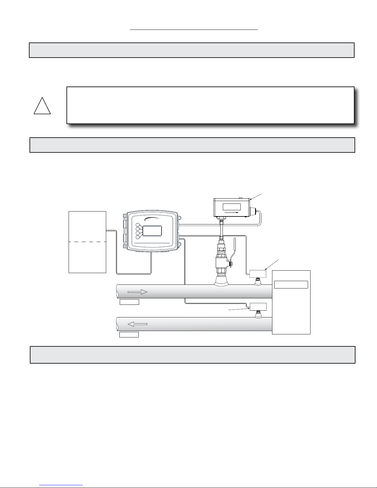
1.2 TYPICAL SYSTEM-20 BTU METER
ONICON’s System-20 is a true heat (Btu) computer, which accepts data from several sensors,
performs a series of computations with that data, and displays and/or transmits the results as an
indication of the amount of heat (Btus) being transferred per unit time or as a totalized amount.
ONICON F-3500
Flow Meter
(F-3500 must be
ordered separately)
Supply Temp
Sensor
Power / Output
24V AC/DC Power
RS-485
(BACnet or MODBUS)
3 Pulse Outputs
1 Analog Output
Up To Three
Pulse Inputs for
Water Meter
Gas Meter
Electric Meter
etc.
Made in the USA
SYSTEM-20
BTU METER
FLOW
Heat Exchanger
Supply
Return Temp
Sensor
Return
1.3 STANDARD FEATURES AND SPECIFICATIONS
• Single mode Btu calculations, in either the heating or cooling mode, are totalized, and
displayed.
• Two-pipe dual mode Btu calculations in both the heating mode and the cooling modes, are
totalized and displayed.
®
• A single isolated RS485 serial interface is provided for BACnet
MS/TP or MODBUS® RTU.
• Three eld congurable pulse outputs may be used for totalization, alarm indication and
mode status.
• Three auxiliary pulse inputs may be used to totalize data from external devices. This data
may also be transmitted via the network interface and viewed on the local display.
• A single eld congurable isolated analog output is provided for energy rate, ow rate or
temperature.
11451 Belcher Road South, Largo, FL 33773 • USA • Tel +1 (727) 447-6140 • Fax +1 (727) 442-5699 • sales@onicon.com
System-20-BTU Meter Installation and Operation Guide 03/18 - 2051-1 / 36985 Page 5
Page 6

1.4 ADDITIONAL REQUIRED HARDWARE
The System-20 must be connected to a suitable volumetric ow meter and a matched pair of
temperature sensors in order to calculate and report heat data.
Flow Meter Model Line Sizes
F-1100 Single Turbine Insertion Flow
Meter
F-1200 Dual Turbin Insertion Flow Meter
F-1300 Inline Turbine Flow Meter
F-3500 Insertion Electromagnetic Flow
Meter
F-2600 Series Vortex Flow Meter
F-3000 Series Inline Electromagnetic Flow
Meters
F-4300 Clamp-on Ultrasonic Flow Meter
F-4600 Inline Ultrasonic Flow Meter
1 ¼" and larger 25
2 ½" and larger 15
¾" and 1" 25
1 ¼" and larger See manual
1" - 12" See manual
¼" and larger 5
2" and larger See manual
½" - 2 ½" See manual
Straight Run
Required
Notes
Can be used in 1" copper
lines
For use in higher
temperature applications
Please refer to ONICON’s ow meter literature, or contact ONICON for help in selecting the ow
meter that will best t your requirements.
Temperature/Sensors
ONICON Standard Temperature Sensors (32° – 200° F)
Pair of solid state temperature sensors with 0 – 20 mA outputs. Suitable for use with uid
temperatures up to 200° F.
Platinum RTD Temperature Sensors (32° – 250° F)
Pair of 4-wire 1000 Ω Platinum RTD temperature sensors. Suitable for use with uid temperatures
up to 250° F.
Please refer to ONICON’s System-20 product literature, or contact ONICON for help in selecting the
temperature sensors and thermowells that will best t your requirements.
1.5 WORKING ENVIRONMENT
The System-20 was designed for installation and use in typical domestic and commercial
environments that are free of corrosive liquids and fumes, direct liquid exposure, temperature
extremes and vibrations.
The System-20 may be installed outdoors in protected spaces away from direct sunlight, rain,
sleet or snow.
The operating ambient air temperature range is -13° F to 140° F. The electrical power should be
relatively clean, free of high frequency noise, large voltage transients, and protected from power
surges and brown outs.
11451 Belcher Road South, Largo, FL 33773 • USA • Tel +1 (727) 447-6140 • Fax +1 (727) 442-5699 • sales@onicon.com
System-20-BTU Meter Installation and Operation Guide 03/18 - 2051-1 / 36985 Page 6
Page 7

1.6 WARRANTY & SERIAL NUMBER
Warranty
ONICON provides a 2-year warranty for this product. Certain exclusions apply. Please refer to
ONICON’s Conditions of Sale for details.
Serial Number
The serial number of your System-20 is located on the top and inside the enclosure. The serial
number is a unique identier for the product. Please have this number available when contacting
ONICON for assistance.
SECTION 2.0: UNPACKING
The System-20 is generally shipped in one package unless optional hardware or equipment is
ordered. (Thermowells may have been shipped in advance.)
2.1 CHECKING THAT YOU HAVE RECEIVED EVERYTHING
Please notify ONICON immediately if any of these items are missing.
• Standard Documentation Includes:
The System-20 BTU Meter Installation and Operation Guide
The System-20 Certicate of Calibration
• The System-20
Remove the System-20 from the shipping carton and inspect it for physical damage. Notify
the freight carrier and ONICON immediately if any items are damaged in transit. Save all
packaging.
Btu meters ordered with a ow meter and temperature sensors will be delivered congured
and programmed for use together as a system. The System-20 and the temperature sensor
serial numbers will match. The ow meter serial number will be shown on the certicate of
calibration and on the System-20 display.
• Temperature Sensors
If ordered, temperature sensors will generally be packed in the same carton with the
System-20. Inspect the sensors and cables for damage. Each sensor will have a label attached
with a serial number.
• Flow Meter
If ordered, the ow meter will be packaged in a separate carton. The ow meter ordered
with this Btu meter came complete with an instruction manual. Please refer to it for detailed
information regarding its installation, commissioning, and operation.
• Flow Meter & Temperature Sensor Installation Hardware
Installation hardware is ordered separately from the System-20, temperature sensors and ow
meter. Note that this hardware is frequently shipped in advance of the meter(s).
11451 Belcher Road South, Largo, FL 33773 • USA • Tel +1 (727) 447-6140 • Fax +1 (727) 442-5699 • sales@onicon.com
System-20-BTU Meter Installation and Operation Guide 03/18 - 2051-1 / 36985 Page 7
Page 8

SECTION 3.0: INSTALLATION
i
The System-20 BTU Meter should be installed by personnel with related knowledge and
experience in the heating, cooling, and uid metering elds. ONICON is available to assist with
technical recommendations and to provide guidance by telephone and/or e-mail during the
installation and commissioning process. On-site eld engineering, installation, and service are
also available at an additional cost. The installer should use good trade practices and must adhere
to all state and local building codes.
Before you begin, clean the external surfaces of all pipes at the installation sites so that they are
free of debris, foreign matter, solids, leak inhibitors, and chemically aggressive substances. Flush
the entire system so that it is free of ux, solder, pipe and tube cuttings and any other debris.
3.1 SITE SELECTION
Careful attention to the site selection for the system components will help ensure an accurate
energy measurement, help the installers with the initial installation, reduce start-up problems,
and make future maintenance easier. For example, do not install the ow meter where it will be
difcult for personnel to perform periodic maintenance. When selecting a site for mounting the
components, refer to Section 1.5: WORKING ENVIRONMENT, as well as the following:
IMPORTANT NOTE
Proper site selection is critical to the performance of this Btu meter. Both the ow sensor and
the temperature sensors must be properly located within the piping system in order to ensure an
accurate energy measurement.
• The System-20
Find an easily accessible location where eld wiring connections can be made and meter
readings can be taken from oor level. Mount the enclosure on a vibration free surface. Avoid
locations such as the plenum of a fan coil, heat exchanger or any housing that may contain
electric motors or other strong sources of electrical interference.
• The Flow Meter
When properly installed, the ow meter will only measure ow associated with that portion
of the piping system for which the energy measurement is being made. The ow meter may
be installed in either the supply or return line. Choose the location with the longest straight
run of unobstructed pipe. Please refer to the ow meter installation manual for specic
information regarding the straight run requirements for the ow meter.
• The Temperature Sensors
The two temperature sensors must be located so they accurately measure only the temperature
of the supply line entering and the return line leaving the portion of the piping system for
which the energy measurement is being made.
If possible, nd an easily accessible location where eld wiring connections can be made from
oor level. This will facilitate future service. Place the temperature sensors away from strong
sources of electrical noise that might affect the performance of the sensors.
One temperature sensor thermowell will need to be placed in the same pipe with the ow
meter. It must be located at least ve pipe diameters downstream of the ow meter leaving
enough clearance to remove either sensor from the pipe without interference from the other
sensor.
11451 Belcher Road South, Largo, FL 33773 • USA • Tel +1 (727) 447-6140 • Fax +1 (727) 442-5699 • sales@onicon.com
System-20-BTU Meter Installation and Operation Guide 03/18 - 2051-1 / 36985 Page 8
Page 9

i
7 5/8"
5 1/2"
5"
∅ 0.875" 5pl
∅ 0.200" 4pl
SYSTEM-20
BTU METER
!
3.2 MECHANICAL INSTALLATION
IMPORTANT NOTE
The components of the ONICON System-20 BTU Measurement System must be congured,
programmed and installed together as a system. Mixing components from different systems may
result in signicant measurement errors.
• Find an easily accessible location where electrical connections can be made and meter
readings can be taken from the oor level.
• Mount the Btu meter on a vibration-free surface. Avoid sites such as the plenum of a fan coil,
heat exchanger, or other housings containing motors.
• The meter must be installed in protected spaces away from direct sunlight, rain, sleet or snow.
DO NOT drill holes in the enclosure. Use only the openings that are provided.
11451 Belcher Road South, Largo, FL 33773 • USA • Tel +1 (727) 447-6140 • Fax +1 (727) 442-5699 • sales@onicon.com
System-20-BTU Meter Installation and Operation Guide 03/18 - 2051-1 / 36985 Page 9
CAUTION
Page 10
3.2.1 Mounting the Enclosure
!
Use four screws for mounting the Btu meter. The mounting surface must be structurally
sound and capable of withstanding a minimum weight of 40 lbs (18 kg).
Use the following screws for mounting.
• Four Machine screws - #10-24 X 1.5”
• Four Wood screws - No. 10 X 1.5”
• Four Concrete screws - 3/16” X 1.5” with ¼" maximum hex, Phillips or slot heads
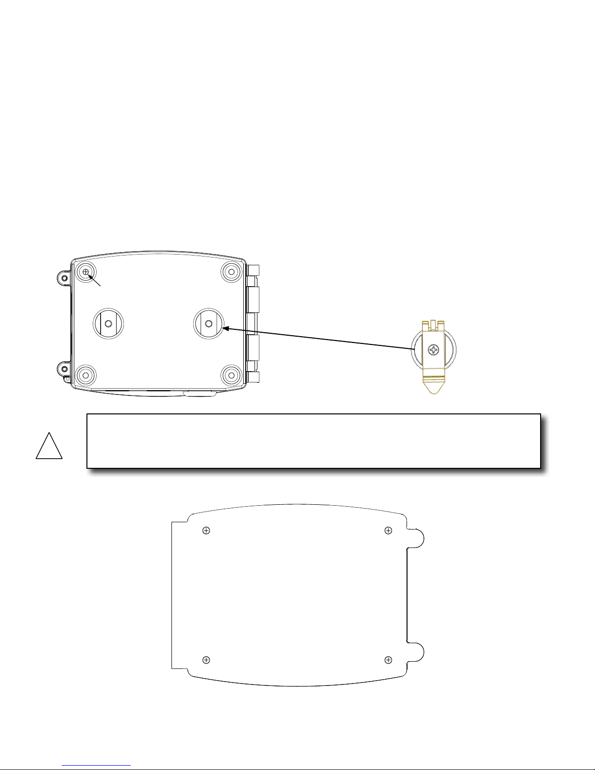
Four mounting holes have been provided in the base of the enclosure shown below. Push
out the rubber seals by inserting the mounting screws. Use the drilling template provided
in Appendix 5 of this manual to drill the 4 holes required to mount the enclosure.
Mounting
Holes
A DIN rail mounting hardware kit has been
provided with this meter. Mount the DIN
rail clips as shown below.
CAUTION
DO NOT USE THE ENCLOSURE AS A TEMPLATE FOR DRILLING HOLES. Do not drill holes in
the enclosure. Use only the openings that are provided.
11451 Belcher Road South, Largo, FL 33773 • USA • Tel +1 (727) 447-6140 • Fax +1 (727) 442-5699 • sales@onicon.com
System-20-BTU Meter Installation and Operation Guide 03/18 - 2051-1 / 36985 Page 10
Page 11

3.2.2 Thermowell Installation
i
!
It is important that no dirt or other foreign material be allowed into the thermowells as this could
affect the thermal response of the system.
3.2.2.1 Standard Thermowells
Standard thermowells are for new construction or scheduled shutdown. The
most common installation methods are shown below. Refer to Appendix A-6 for
thermal insulator installations. Consult ONICON for special applications.
IMPORTANT NOTE
NOTES: 1. Thermowell length varies with pipe size.
2. Use no additional bushings to ensure that tip of thermowell is inserted into ow stream.
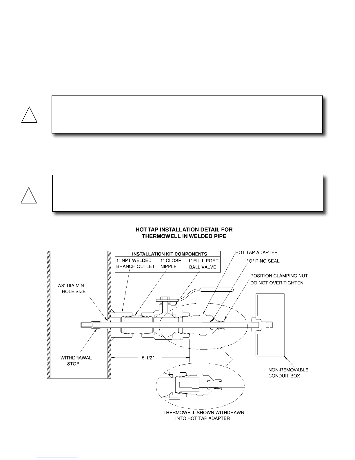
3.2.2.2 Hot Tap Thermowells
Hot tap thermowells are designed for retrot applications where it is not practical to
isolate and drain the pipe section prior to installation. The thermowell is installed
through a 1” full port ball valve as shown in the drawing on next page. A wet
tap drilling machine equipped with a
installation.
Install the valve assembly as shown in the drawing on the next page and then
drill the
been installed and the hole has been drilled, the thermowell can be inserted into
the ow stream without a system shutdown.
7/8” hole using the wet tap drilling machine. Once the valve assembly has
7/8” drill is required to perform this type of
WARNING
SYSTEM MAY BE UNDER HIGH PRESSURE. Be sure to hold the conduit box rmly by hand before
slowly loosening the position clamping nut when installing, adjusting or removing the thermowell.
Failure to do this will allow the pressure to suddenly and rapidly force the thermowell from the
pipe, potentially causing serious injury. The thermowell could also be damaged or break apart
causing a break in the water seal resulting in the loss of large amounts of water.
11451 Belcher Road South, Largo, FL 33773 • USA • Tel +1 (727) 447-6140 • Fax +1 (727) 442-5699 • sales@onicon.com
System-20-BTU Meter Installation and Operation Guide 03/18 - 2051-1 / 36985 Page 11
Page 12
INSERTION OF THE HOT TAP THERMOWELL
!
!
1. Calculate the insertion force (lbs) required by multiplying the system pressure
(psig) by 0.11. The person inserting the thermowell should ensure adequate
footing for the force required prior to opening the valve.
2. After applying thread seal tape, thread the hot tap adapter into the valve.
Firmly grasp the wiring enclosure, loosen the position clamping nut, open the
valve, and carefully push the thermowell into the ow stream. Use the attached gauge to set the insertion depth.
CAUTION
Excessive vibration can damage the thermowell. Insert the thermowell to the proper depth using
gauge supplied as shown. Reduce the insertion depth as necessary if strong vibrations are felt
during insertion, making certain that the tip of the thermowell remains fully in the ow stream.
3. Carefully tighten the position clamping nut that is located at the top of the
1" NPT hot tap adapter tting. Do not release the wiring enclosure until the
position clamping nut has been tightened.
CAUTION
DO NOT OVER TIGHTEN THE POSITION CLAMPING NUT. If uid leaks, do not attempt to
correct by tightening this nut further. An internal o-ring seals the uid. Contact ONICON for
assistance in the event of a leak.
11451 Belcher Road South, Largo, FL 33773 • USA • Tel +1 (727) 447-6140 • Fax +1 (727) 442-5699 • sales@onicon.com
System-20-BTU Meter Installation and Operation Guide 03/18 - 2051-1 / 36985 Page 12
Page 13

REMOVAL OF THE HOT TAP THERMOWELL
i
!
WARNING
Maintain a rm hold on the wiring enclosure until the thermowell is completely withdrawn and
the valve is closed.
1. System pressure will try to push the thermowell out of the ow stream when the
clamping nut is released. Be sure to establish safe footing prior to loosening the
clamping nut. The force pushing out against the thermowell is the same as the
insertion force.
2. Grasp the wiring enclosure rmly, holding the thermowell in the pipe and then
loosen the position clamping nut. Slowly withdraw the thermowell from the pipe.
3. After the thermowell is completely withdrawn, carefully close the isolation valve.
IMPORTANT NOTE
Rotating the thermowell as you slowly withdraw it through the valve will ensure that the lower
tip is fully withdrawn and completely free of the valve. If resistance is felt when closing the
valve, open valve fully and rotate the well as you pull it further out of the pipe.
3.2.3 Temperature Sensor Installation
When ordered with the System-20, temperature sensors are factory matched and tagged
by serial number to a specic Btu meter. ONICON standard temperature sensors are also
designated and labeled as the SUPPLY or RETURN sensor and must be installed per these
labels.
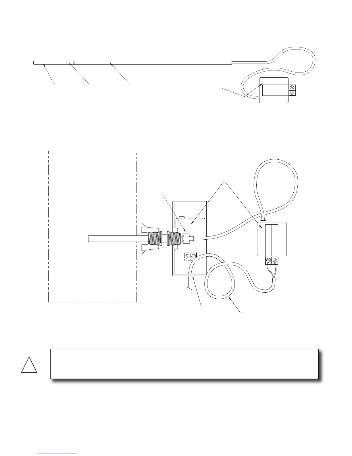
3.2.3.1 ONICON Standard Temperature Sensor Installation
ONICON standard temperature sensors must be used as a pair to maintain
differential accuracy. They are also designated and labeled as the SUPPLY or
RETURN sensor and must be installed accordingly. To install, apply a thin coat
of thermal compound to the sensor tip area and insert it all the way into the
thermowell until it contacts the bottom of the cavity. Gently tighten the retainer
nut. DO NOT OVER TIGHTEN. The thermowell completely seals the plumbing
system without the retainer nut. The only purpose for the nut is to ensure that the
sensor tip will remain in contact with the bottom of the thermowell.
11451 Belcher Road South, Largo, FL 33773 • USA • Tel +1 (727) 447-6140 • Fax +1 (727) 442-5699 • sales@onicon.com
System-20-BTU Meter Installation and Operation Guide 03/18 - 2051-1 / 36985 Page 13
Page 14
STANDARD THERMOWELL ASSEMBLY
FOR SYSTEM-10 BTU METER
SHOWN WITH TEMPERATURE SENSOR
TEMPERATURE
SENSOR
PLASTIC
END PIECE
SPACER SLEEVE
(Length varies with
thermowell length)
ELECTRONICS
MODULE
SUPPLY
S/N 123456
SIGNAL
(RED)
REFERENCE
(BLACK)
!
TEMPERATURE SENSOR
TEMPERATURE SENSOR INSTALLED IN THERMOWELL
PLACE ELECTRONICS
MODULE IN BOX AFTER
CONNECTING WIRES.
RETAINING NUT
(Do NOT Overtighten)
REFERNECE (BLACK)
SIGNAL
S/N 123456
SUPPLY
(RED)
PROVIDE #18-22 TWISTED
1/2” HOLE FOR
CONDUIT OR
STRAIN RELIEF
FITTING
SHIELDED PAIR. COIL ONE
FOOT OF EXTRA CABLE IN
CONDUIT BOX.
CAUTION
DO NOT OVERTIGHTEN. The thermowell completely seals the plumbing system. Screwing in the
sensor just ensures that the sensor tip will remain in contact with the bottom of the thermowell.
11451 Belcher Road South, Largo, FL 33773 • USA • Tel +1 (727) 447-6140 • Fax +1 (727) 442-5699 • sales@onicon.com
System-20-BTU Meter Installation and Operation Guide 03/18 - 2051-1 / 36985 Page 14
Page 15

System-20-BAC Enclosure Label
3.3 POWER AND SIGNAL WIRING CONNECTIONS
The System-20 is provided with three ¾" conduit openings along the bottom of the enclosure
for power and signal cables. Two openings are provided with knockout seals. The power cable
should enter the enclosure through the right hand opening. Do not remove the seals from
unused openings. To access the wiring connections, remove the two cover screws shown
below.
Pulse Inputs
Name TB2 Description
IN 1 (+) TB2-1
IN 1 (-) TB2-2
IN 2 (+) TB2-3
IN 2 (-) TB2-4
IN 3 (+) TB2-5
For use with open collector sinking
and dry contact outputs only
Input rating
Pulse duration: 50 ms minimum
Sinking current: 1 mA maximum
IN 3 (-) TB2-6
RS485 Termination Resistor
Name JMP1 Description
120 Ohm JMP1-1
120 Ohm JMP1-2
None JMP1-3
Jumper position 1 & 2 = 120
Ohm Termination
Jumper positions 2 & 3 = No
termination
RS485 (20 – 24 AWG wire)
Name TB1 Description
RS485 B (+) TB1-1
RS485 A (-) TB1-2
RS485 Common TB1-3
RS485 Unit Load = ¼
Recommended maximum
device per segment = 32
Shield TB1-4
Temperature (ONICON Standard Sensors)
Name TB5 Description
SUPTEMP (+) TB5-1
SUPTEMP (-) TB5-2
SHIELD TB5-3
RETTEMP (+) TB5-4
RETTEMP (-) TB5-5
Each sensor is individually
labeled as supply (SUP)
and return (RET) and
must be connected to the
appropriate terminals.
RTD Supply & RTD Return
Name TB6 & TB7 Description
(A) TB6-1 / TB7-1 RTD signal lead (A)
(A) TB6-2 / TB7-2
Compensation lead (A) not
used with 2-wire RTDs
(B) TB6-3 / TB7-3 RTD signal lead (B)
(B) TB6-4 / TB7-4
Compensation lead (B) not
used with 2-wire RTDs
Pulse Outputs
Name TB3 Description
OUT 1 (+) TB3-1
OUT 1 (-) TB3-2
OUT 2 (+) TB3-3
OUT 2 (-) TB3-4
OUT 3 (+) TB3-5
OUT 3 (-) TB3-6
TERMINATED UNTERMINATED
JMP1 RS485 LOAD
TB1 RS-485 TB2 PULSE IN TB3 PULSE OUT TB4 ANA OUT
1 2 3 4 1 2 3 4 5 6 1 2 3 4 5 6 1 2 3 4
RS485COM
RS485 -
RS485+
TB5 TEMPERATURE TB6 RTD SUP TB7 RTD RET TB8 TURB TB9 FLOWMETER
1 2 3 4 5 1 2 3 4 1 2 3 4 1 2 3 1 2 3 4 5
RETTEMP (+)
SHIELD
SUPTEMP (-)
SUPTEMP (+)
10/31/16
Opto coupled solid state relay output.
100 V maximum input voltage
30 Ω maximum ON resistance
80 mA maximum current
0.5 Hz maximum pulse rate
Pulse duration: Selectable 50, 100,
500 or 1000 ms
OUT1 (+)
IN 3 (-)
IN 3 (+)
IN 2 (-)
IN 2 (+)
IN 1 (-)
IN 1 (+)
SHEILD
(B)
(B)
(A)
(A)
(B)
(B)
(A)
(A)
RETTEMP (-)
2 4
2 4
2 4
WIRE
WIRE
2 4
WIRE
WIRE
AC/DC POWER IN AUX POWER OUT
!
24V ONLY
4-20 mACOM
4-20mAOUT
OUT 3 (-)
OUT 3 (+)
OUT2 (-)
OUT 2 (+)
OUT 1 (-)
FREQIN
4-20mA IN
24 VDC (=)
TURBCOM
TURB FREQ
24V TURB
1 2 3 4 5 6
24 V N (-)
24V L (+)
EARTH
24 V N (-)
24V L (+)
0-10VOUT
SIG COMM
2-wire / 4-wire RTS Selection Jumpers (4 places)
Name 2-4 Wire Description
2 JMP1-1
Select jumper positions 1
& 2 for 2-wire RTD
JMP1-2
4 JMP1-3
Select jumper positions 2
& 3 for 4-wire RTD
0-10 VCOM
24VDC (-)
EARTH
Cover Screws
Analog Output
Name TB4 Description
4-20 mA Out TB4-1
4-20 mA Common TB4-2
0-10 V Out TB4-3
0-10 V Common TB4-4
Turbine Flow Meter Input
Name TB8 Description
24 V TURB TB8-1
TURB FREQ TB8-2
TURB COMMON TB8-3 Isolated Common
Name TB9 Description
24 VDC (+) TB9-1
4-20 mA IN TB9-2
FREQ IN TB9-3
Signal Common TB9-4 Signal common only
24 VDC (-) TB9-5 24 VDC common
AC/DC POWER INPUT
Name Term # Description
24 V L (+) 1
24 V N (-) 2
EARTH 3
24 V L (+) 4
24 V N (-) 5
EARTH 6
4-20 mA maximum load
resistance 750 Ohms
Voltage output selectable as
0-10 V or 0-5 V
Isolated 24 VDC Supply, 100
mA maximum current
5-24 VDC, 500 Hz maximum
frequency
Flow Meter Input
24 VDC, 250 mA maximum
current
Loop power = TB9-1 & TB9-2 /
Active output = TB9-2 & TB9-4
5-24 VDC, 500 Hz maximum
frequency
20 – 28 V AC/DC, 50-60 Hz
500 mA DC input current
1A AC input current
Instrument earth
11451 Belcher Road South, Largo, FL 33773 • USA • Tel +1 (727) 447-6140 • Fax +1 (727) 442-5699 • sales@onicon.com
System-20-BTU Meter Installation and Operation Guide 03/18 - 2051-1 / 36985 Page 15
Page 16

SECTION 4.0: SYSTEM-20 START-UP AND COMMISSIONING
!
NEXT
SEL
More Totals
Meter Data
! Alarm
Diagnostic
EXIT
BACK
4.1 START-UP
When power is rst applied to the meter the display will be illuminated and the following start
screen will appear. Momentarily press SEL (select) to access the operating mode (User Screens)
display pages.
User Screens
Commissioning
NEXT
SEL
Verify that the meter is functional by stepping through the display pages and conrming the ow
rate and temperature data is within expected norms. Momentarily press NEXT or BACK to change
the displayed page. A complete list of the display pages is provided on the following pages.
BACK
NEXT
MENU
When reviewing the displayed data, note the factory programmed engineering units on each
display page (e.g. kBtu, gallons, kBtu/h, gpm, °F, etc.). Note any changes that may be necessary.
These will need to be made during commissioning.
Energy Total
!
Alarm Indication
!
0
Unit of Measure
kBtu
When reviewing the Supply and Return temperature display pages, note which one has the word
“FLOW” in the lower left corner of the page. This is an indication of the ow sensor location in
the piping system. Verify the actual location of the ow sensor in the piping system. It is critical
that the correct location (supply or return) be programmed into the meter.
During start-up and commissioning, the FLOW location must be properly identied as being
in the supply or return pipe of the heat exchange circuit. The sensor’s position must then be
programmed into the meter. Failure to do so will result in signicant errors in both the ow
and energy measurements.
To return to the commissioning mode from the user screens, momentarily press MENU.
The following page will appear. Momentarily press EXIT to return to the start screen.
11451 Belcher Road South, Largo, FL 33773 • USA • Tel +1 (727) 447-6140 • Fax +1 (727) 442-5699 • sales@onicon.com
System-20-BTU Meter Installation and Operation Guide 03/18 - 2051-1 / 36985 Page 16
CAUTION
Page 17

4.1.1 Single and Dual Mode Display Pages
Single Mode Dual Mode
BACK
BACK
Run hours
NEXT
MENU
BACK
Auxiliary Input 3
NEXT
MENU
BACK
Auxiliary Input 2
NEXT
MENU
hours
Counts
Counts
Energy Total
NEXT
MENU
!
0
!
*
0
!
*
0
kBtu
!
0
BACK
NEXT
MENU
BACK
NEXT
MENU
BACK
NEXT
MENU
Volume Total
gallons x 1
Energy Rate
kBtu/h x 1
Volume Rate
!
0
!
0
!
0
gpm x 1
BACK
Run hours
NEXT
MENU
BACK
Auxiliary Input 3
NEXT
MENU
BACK
Auxiliary Input 2
NEXT
MENU
hours
*
Counts
*
Counts
BACK
Energy Total
NEXT
MENU
Mode 1
!
0
!
0
!
0
kBtu
!
0
BACK
NEXT
MENU
BACK
NEXT
MENU
BACK
NEXT
MENU
Energy Total
Mode 2
Volume Total
Mode 1
Volume Total
Mode 2
!
0
kBtu
!
0
gallons x 1
!
0
gallons x 1
BACK
NEXT
MENU
BACK
NEXT
MENU
Supply
Temperature
Deg F
Return
Temperature
Deg F
BACK
Auxiliary Input 1
NEXT
MENU
BACK
Delta Temperature
NEXT
MENU
Counts
0.0
Deg F
!
*
0
!
* Auxiliary input pages only appear when enabled.
0.0
0.0
0.0
BACK
NEXT
MENU
BACK
NEXT
MENU
BACK
NEXT
MENU
Energy Rate
kBtu/h x 1
Volume Rate
Supply
Temperature
!
0
!
0
gpm x 1
!
0.0
Deg F
!
BACK
!
!
Auxiliary Input 1
NEXT
MENU
BACK
Mode Status
NEXT
MENU
BACK
Delta Temperature
NEXT
MENU
*
Counts
Mode 2
0.0
Deg F
!
0
!
!
BACK
Return
Temperature
NEXT
MENU
Deg F
11451 Belcher Road South, Largo, FL 33773 • USA • Tel +1 (727) 447-6140 • Fax +1 (727) 442-5699 • sales@onicon.com
System-20-BTU Meter Installation and Operation Guide 03/18 - 2051-1 / 36985 Page 17
Page 18

4.1.2 Additional Display Pages
NEXT
MENU
Low Flow
Alarm
NEXT
MENU
0
Reset Count
NEXT
MENU
0
Max 200
Flow Count
BACK
EXIT
BACK
EXIT
BACK
EXIT
Diagnostics
NEXT
MENU
Flow Meter
Serial Number
NEXT
MENU
NEXT
MENU
HH:MM:SS
Current Time
NEXT
MENU
App:
Boot:
Versions
NEXT
MENU
0
Serial Number
BACK
EXIT
BACK
EXIT
BACK
EXIT
BACK
EXIT
BACK
EXIT
Meter Data
NEXT
MENU
YYYY/MM/DD
Manuafacture Date
NEXT
MENU
Current Date
BACK
EXIT
BACK
EXIT
YYYY/MM/DD
Alarms
Alarm Mesages
Flow Temp Open
Low Flow
Low Supply Temp
Low Return Temp
dt< Minimum
Temperature Sensor
Serial Number
Single Mode
More Totals
EXIT
YTD Energy
BACK
NEXT
MENU
EXIT
User Energy Total
BACK
NEXT
MENU
EXIT
Prev. Yr Volume
BACK
NEXT
MENU
0
KBtu
0
gallons
YTD Energy & Volume Totals reset at
12:01 AM on January 1st
Prev. Yr. Energy & Volume Totals update at
12:01 AM on January 1st
0
kBtu
EXIT
BACK
NEXT
MENU
EXIT
BACK
NEXT
MENU
YTD Volume
gallons
Prev. Yr Energy
kBtu
Dual Mode
More Totals
EXIT
YTD Energy
BACK
NEXT
MENU
Mode 1
EXIT
User Energy Total
0
0
BACK
NEXT
MENU
Mode 2
EXIT
User Energy Total
BACK
NEXT
MENU
Mode 1
EXIT
Prev. Yr Volume
BACK
NEXT
MENU
Mode 2
EXIT
Prev. Yr Volume
BACK
NEXT
MENU
Mode 1
0
kBtu
0
kBtu
0
gallons
0
gallons
kBtu
0
EXIT
YTD Energy
BACK
NEXT
MENU
Mode 2
EXIT
YTD Volume
BACK
NEXT
MENU
Mode 1
EXIT
YTD Volume
BACK
NEXT
MENU
Mode 2
EXIT
Prev. Yr Energy
BACK
NEXT
MENU
Mode 1
0
kBtu
0
gallons
0
gallons
0
kBtu
User Energy Totals reset via MODBUS
Meter Data
Diagnostics
EXIT
Prev. Yr Energy
BACK
NEXT
MENU
Mode 2
kBtu
0
Alarms
11451 Belcher Road South, Largo, FL 33773 • USA • Tel +1 (727) 447-6140 • Fax +1 (727) 442-5699 • sales@onicon.com
System-20-BTU Meter Installation and Operation Guide 03/18 - 2051-1 / 36985 Page 18
Page 19

NEXT
Meter Factor
XX.XXX
EXIT
BACK
NEXT
BACK
EDIT
EXIT
Full Scale
Maximum Flow
XXXX
NEXT
BACK
EDIT
EDIT
0 - 9999999
EXIT
Flow Damping
1
1 - 32
NEXT
BACK
EDIT
Pulses per units
% of maximum flow
EXIT
Flow Input Source
Frequency
NEXT
BACK
EDIT
EXIT
Flow Input Source
4-20Ma
NEXT
BACK
EDIT
EXIT
Energy Units
kBtu x 1
Select Units
NEXT
BACK
EDIT
EXIT
Energy Multiplier
EXIT
Energy Rate
kBtu/h x 1
Select Units
NEXT
BACK
EDIT
NEXT
BACK
EDIT
NEXT
Energy Rate Multiplier
kBtu/h x 1
EXIT
BACK
EXIT
Energy Damping
1
NEXT
BACK
EDIT
EDIT
1 - 32
kBtu x 1
X.X
NEXT
Mode
Single
EXIT
BACK
N
EXT
BACK
EDIT
Single/Dual/BiDirectional
EDIT
EXIT
Flow Multiplier
NEXT
Volume Multiplier
gal x 1
EXIT
BACK
NEXT
BACK
EDIT
EXIT
Flow Units
gpm x 1
NEXT
BACK
EDIT
EDIT
Select Units
gpm x 1
NEXT
Medium
Water
EXIT
BACK
EDIT
EXIT
Flow Rate Units
gpm x 1
Select Units
NEXT
BACK
EDIT
NEXT
Flow 20mA
XXXX
EXIT
BACK
EXIT
Low Flow Cutoff
X.X
NEXT
BACK
EDIT
EDIT
% of maximum flow
EXIT
Flow Damping
1
1 - 32
NEXT
BACK
EDIT
0 - 9999999
EXIT
Meter Volume Units
gallons
Se
lect Units
NEXT
BACK
EDIT
EXIT
Low Flow Cutoff
EXIT
Volume Units
gallons
Select Units
Units of Measure Settings
4.2 COMMISSIONING
The last step in the installation process is commissioning the meter. Commissioning is a two-step
process. The rst step is to review the mechanical installation to conrm that the ow sensor and
temperature sensor(s) are properly located in the piping system. The second step is a review of
the meter program settings. Both steps must be completed in order to nish the installation. A
simple commissioning checklist is shown below. A copy of this may be found online at
www.onicon.com/system20.html.
Commissioning Checklist
Part 1 Mechanical Installation
Conrm that the system components are
installed in the correct locations (Sec. 1.5 & 3.1).
Conrm that the ow sensor is properly installed
and correctly oriented with respect to ow
direction (ow meter manual).
Part 2 Programming
Conrm that the ow sensor location in the
piping system (supply or return) is programmed
into the meter (Sec. 4.1 & 4.2.1).
Verify that the Units of Measure Settings in the
meter are correct (Sec. 4.1 & 4.2.1).
Conrm that there are no alarm indications and
the meter is functional (Sec. 4.1.2 & 5.0).
4.2.1 Commissioning Following Initial Power-up
During initial power-up, the display pages will appear when the
commissioning option is selected. The settings shown below allow
the installer to set MODBUS
®
or BACnet® parameters, the ow
EXIT
BACK
NEXT
EDIT
sensor location (supply or return pipe) and the date and time. If
the factory pre-programmed engineering units for ow, energy and
temperature are correct, press SAVE to exit commissioning once
the correct date has been set. Momentarily press NEXT if you wish
access the remaining commissioning mode display pages shown
on the following pages.
Protocol
None
Initial Power-up
Short Commissioning
Protocol
EXIT
BACK
Modbus
NEXT
EDIT
Modbus Address
EXIT
BACK
NEXT
EDIT
Baud Rate
EXIT
BACK
NEXT
EDIT
Parity
EXIT
BACK
NEXT
EDIT
Odd Even None
Stop Bits
EXIT
BACK
NEXT
EDIT
1
0 - 247
19200
None
1
1 2
Short Commissioning
Set Meter
EXIT
BACK
Next to complete Install
settings.
or adjust
NEXT
Protocol
EXIT
BACK
BACnet
NEXT
EDIT
BACnet Address
EXIT
BACK
NEXT
EDIT
0 - 127
Instance Number
EXIT
BACK
57017
NEXT
EDIT
0 - 4194302
Baud Rate
EXIT
BACK
NEXT
EDIT
Max Master
EXIT
BACK
NEXT
EDIT
2 - 127
Set Time
EXIT
BACK
HH:MM:SS
NEXT
EDIT
Set Date
EXIT
BACK
YYYY:MM:DD
NEXT
EDIT
Meter Location
EXIT
BACK
Return
NEXT
EDIT
Flow Meter
EXIT
Serial Number
BACK
NEXT
XXXXXX
EDIT
Location Tag
EXIT
BACK
NEXT
EDIT
Set Meter
EXIT
NEXT edits units of
BACK
measure
NEXT
SAVE completes install
SAVE
with current settings
1
38400
2
Text
11451 Belcher Road South, Largo, FL 33773 • USA • Tel +1 (727) 447-6140 • Fax +1 (727) 442-5699 • sales@onicon.com
System-20-BTU Meter Installation and Operation Guide 03/18 - 2051-1 / 36985 Page 19
Page 20

Continued From Previous Page
Supply Temperature
20mA
Return Temperature
4mA
Return Temperature
20mA
EXIT
Temperature Sensor
Type
1k Ohm RTD
NEXT
BACK
EDIT
NEXT
X
EXIT
BACK
EXIT
XXX
NEXT
BACK
EDIT
EDIT
EXIT
Supply Temperature
4mA
X
NEXT
BACK
EDIT
EXIT
Temperature Sensor
Type
Scalable
NEXT
BACK
EDIT
EXIT
XXX
NEXT
BACK
EDIT
Flow Input Source
EXIT
BACK
NEXT
EDIT
Flow Damping
EXIT
BACK
NEXT
EDIT
Flow Rate Units
EXIT
BACK
NEXT
EDIT
Select Units
Flow 20mA
EXIT
BACK
NEXT
EDIT
0 - 9999999
Low Flow Cutoff
EXIT
BACK
NEXT
EDIT
% of maximum flow
4-20Ma
1 - 32
gpm x 1
XXXX
X.X
Units of Measure Settings
Energy Units
Mode
EXIT
BACK
NEXT
EDIT
EXIT
BACK
NEXT
EDIT
EXIT
BACK
NEXT
EDIT
EXIT
1
BACK
NEXT
EDIT
EXIT
BACK
NEXT
EDIT
EXIT
BACK
NEXT
EDIT
EXIT
BACK
NEXT
EDIT
EXIT
BACK
NEXT
EDIT
EXIT
BACK
NEXT
EDIT
Single
Single/Dual/BiDirectional
Medium
Water
Flow Input Source
Frequency
Flow Damping
1 - 32
Meter Volume Units
gallons
Select Units
Meter Factor
XX.XXX
Pulses per units
Full Scale
Maximum Flow
XXXX
0 - 9999999
Low Flow Cutoff
X.X
% of maximum flow
Volume Units
gallons
Select Units
1
EXIT
BACK
NEXT
EDIT
Select Units
Energy Multiplier
EXIT
BACK
NEXT
EDIT
Energy Rate
EXIT
BACK
kBtu/h x 1
NEXT
EDIT
Select Units
Energy Rate Multiplier
EXIT
BACK
NEXT
EDIT
Energy Damping
EXIT
BACK
NEXT
EDIT
kBtu x 1
kBtu x 1
kBtu/h x 1
1 - 32
1
11451 Belcher Road South, Largo, FL 33773 • USA • Tel +1 (727) 447-6140 • Fax +1 (727) 442-5699 • sales@onicon.com
System-20-BTU Meter Installation and Operation Guide 03/18 - 2051-1 / 36985 Page 20
Volume Multiplier
EXIT
BACK
NEXT
EDIT
Flow Units
EXIT
BACK
NEXT
EDIT
Select Units
Flow Multiplier
EXIT
BACK
NEXT
EDIT
gal x 1
gpm x 1
gpm x 1
Page 21

Units of Measure Settings Continued
Continued From Previous Page
Temperature Sensor
EXIT
Type
BACK
1k Ohm RTD
NEXT
EDIT
Temperature Sensor
EXIT
Type
BACK
NEXT
EDIT
Supply Temperature
EXIT
4mA
BACK
NEXT
EDIT
Supply Temperature
EXIT
20mA
BACK
NEXT
EDIT
Return Temperature
EXIT
4mA
BACK
NEXT
EDIT
Scalable
XXX
Temperature
EXIT
BACK
NEXT
EDIT
EXIT
BACK
NEXT
EDIT
EXIT
BACK
NEXT
EDIT
EXIT
X
X
BACK
NEXT
EDIT
EXIT
BACK
NEXT
EDIT
EXIT
BACK
NEXT
EDIT
Deg F
Select Units
Temperature Sensor
Serial Number
XXXXXX
Temperature Sensor
Type
ONICON
Supply Temperature
Offset
+0.000
Supply Temperature
Slope
10.000
Return Temperature
Offset
+0.000
Pulse Output 1
EXIT
BACK
Energy Total
NEXT
EDIT
Select Type
Pulse Output 2
EXIT
BACK
Volume Total
NEXT
EDIT
Select Type
Pulse Output 3
EXIT
BACK
NEXT
EDIT
Select Type
Pulse Duration
EXIT
BACK
NEXT
EDIT
Volume Pulse Scaling
EXIT
BACK
NEXT
EDIT
elect Multiplier
S
EXIT
Analog Output
BACK
Energy Rate
NEXT
EDIT
500 ms
S
elect Type
Alarm
x 1
Return Temperature
EXIT
20mA
BACK
NEXT
EDIT
XXX
Return Temperature
EXIT
Slope
BACK
NEXT
EDIT
Configure Auxiliary
EXIT
Input 1
BACK
NEXT
EDIT
Auxiliary Input
EXIT
Label 1
BACK
NEXT
EDIT
Configure Auxiliary
EXIT
Input 2
BACK
NEXT
EDIT
Auxiliary Input
EXIT
Label 2
BACK
NEXT
EDIT
Configure Auxiliary
EXIT
Input 3
BACK
NEXT
EDIT
10.000
Pulse
Counts
Pulse
Counts
Pulse
Analog Volts Signal
EXIT
BACK
NEXT
EDIT
Analog Output Max
EXIT
BACK
NEXT
EDIT
Energy Rate - kBtu/h
Analog Output Min
EXIT
BACK
NEXT
EDIT
Energy Rate - kBtu/h
Set Meter
BACK
Press NEXT edit units
of measure
NEXT
SAVE completes install
with current settings
EDIT
0 - 10V
S
elect Signal
2000
0
11451 Belcher Road South, Largo, FL 33773 • USA • Tel +1 (727) 447-6140 • Fax +1 (727) 442-5699 • sales@onicon.com
System-20-BTU Meter Installation and Operation Guide 03/18 - 2051-1 / 36985 Page 21
EXIT
BACK
NEXT
EDIT
Auxiliary Input
Label 3
Counts
Page 22

4.3 SEALING THE METER
Once commissioning is complete, install the security seal.
SECTION 5.0: DIAGNOSTIC FUNCTIONS
The ONICON System-20 has self diagnostic functions that continually monitor key operating
parameters. A list of the alarm messages is shown below.
Install Security
Seal Here
Displayed Message Description
System Fault This message indicates a hardware malfunction. The meter will not
calculate energy in this state.
Dt< Minimum This is a warning message that the delta temperature is low.
Empty Pipe The pipe is empty.
Flow RTD Open The SUPPLY temperature sensor in the ow body is reading open.
The meter will not calculate energy in this state.
Flow RTD Short The SUPPLY temperature sensor in the ow body is reading as a short
circuit. The meter will not calculate energy in this state.
Remote RTD Open The remote RETURN temperature sensor is reading open. The meter
will not calculate energy in this state.
Remote RTD Short The remote RETURN temperature sensor is reading as a short circuit.
The meter will not calculate energy in this state.
Low Flow The ow reading is below the minimum ow threshold of the meter
(e.g. 0.03 gpm for ½” meter). The meter will not calculate energy in
this state.
High Flow This is a warning message that the ow reading is above the
maximum ow rate of the meter (e.g. 15 gpm for ½” meter).
11451 Belcher Road South, Largo, FL 33773 • USA • Tel +1 (727) 447-6140 • Fax +1 (727) 442-5699 • sales@onicon.com
System-20-BTU Meter Installation and Operation Guide 03/18 - 2051-1 / 36985 Page 22
Page 23

SECTION 6.0: BACnet® MS/TP
BACnet® MS/TP, serial interface connections are connected at terminal block TB1.
Transceiver: 2-wire, half-duplex (1/4 unit load)
BACnet® address (MAC address) range: 1 - 255 (Default: 017)
Device Instance: 0 - 4,194,303 (Default: 57017)
Baud rate: 9600, 19200, 38400 or 76800 (Default: 38400)
Termination: 120 Ω or none (Default: none)
Biasing: None
Flow control: None
6.1 BACnet® OBJECT TYPES
BACnet® Object Type and Number of Objects Implemented
Device 1
Analog Input 10
Analog Value 34
Binary Value 12
Multi-State Object 1
Trend Log Multiple 1
6.2 PROTOCOL IMPLEMENTATION STATEMENT
BACnet® Protocol Revision: 10
Device Prole (Annex L): BACnet® Application Specic Controller (B-ASC)
MS/TP master (Clause 9), baud rate(s): 9600, 19200, 38400 & 76800
Device Address Binding: No
BBMD support registration by Foreign Devices: No
Character Set Supported: ANSI X3.4
BACnet® Interoperability Building Blocks Supported (Annex K):
Data Sharing - ReadProperty-B (DS-RP-B)
Data Sharing - ReadProperty Multiple - B (DS-RPM-B)
Data Sharing - WriteProperty-B (DS-WP-B)
Data Sharing - WriteProperty Multiple - B (DS-WPM-B)
Device Management - Dynamic Device Binding - B (DM-DDB-B)
Device Management - Dynamic Object Binding - B (DM-DOB-B)
Device Management - DeviceCommunicationControl-B (DM-DCC-B)
Device Management - Time Synchronization - B (DM-TS-B)
Device Management - UTC Time Synchronization - B (DM-UTC-B)
Trending - View and Modify Multiple Values - I - B (T-VMMV-I-B)
Standard Object Types Supported:
Device Object Binary Value Object
Analog Input Object Multi-State Value
Analog Value Object Trend Log Multiple
11451 Belcher Road South, Largo, FL 33773 • USA • Tel +1 (727) 447-6140 • Fax +1 (727) 442-5699 • sales@onicon.com
System-20-BTU Meter Installation and Operation Guide 03/18 - 2051-1 / 36985 Page 23
Page 24

6.3 DEVICE OBJECT
Property Default Value Read-only or
Writable
Object Identier 57017 Writable 0-4,194,303
Object Name System-20-XXXXXX Read-only
Object Type Device Read-only
System Status Operational Read-only
Vendor Name ONICON Inc. Read-only
Model Name System-20 Read-only
Firmware Rev. 000.000.000 Read-only
Location Customer Location Writable 32 char. Max
Description Customer Description Writable 32 char. Max
Protocol Version 1 Read-only
Protocol Revision 10 Read-only
Services Supported Read property, Read property multiple, Write
property, Write property multiple, Read
range, Who-has, I have, Who-is, I-am, Device
communications control, Time synchronization,
UTC time synchronization
Object Types Supported Analog input, Analog value, Binary input, Device,
Multi-state value, Trend log multiple
Object List (Device, 57017), (analog input, 1 – 10),
(analog value, 1 – 24), (binary value, 1 – 10),
(trend log multiple, 1), (multi-state value, 1)
Max ADPU Length 480 Read-only
Local Time Device current time Read-only
Local Date Device current date Read-only
UTC Offset -300 Writable
Daylight Savings Status False Writable
APDU Time-out 6000 Read-only
# of APDU Retries 3 Writable
Max Master 127 Read-only
Device Address Binding N/A Read-only Active
Database Revision 1 Read-only
Read-only
Read-only
Read-only
Comment
11451 Belcher Road South, Largo, FL 33773 • USA • Tel +1 (727) 447-6140 • Fax +1 (727) 442-5699 • sales@onicon.com
System-20-BTU Meter Installation and Operation Guide 03/18 - 2051-1 / 36985 Page 24
Page 25

6.4 ANALOG INPUT(S)
Property Default Value Read-only or Writable
Object Identier Analog input 1 to 10 Read-only
Object Name Various Read-only
Object Type Analog-input Read-only
Present Value REAL Writable
Description Analog-input,# Name Read-only
Status Flags (F,F,F,F) Read-only
Event State Normal Read-only
Reliability No-fault-detected Read-only
Out-of-Service FALSE Writable
Update interval 100 Read-only
Units Various Read-only
Min-Present-Value -1000000000 Read-only
Max-Present-Value 1000000000 Read-only
Resolution 0.000001 Read-only
Objects List
Object Identier Function
Analog input 1 Energy rate
Analog input 2 Volume rate
Analog input 3 Supply temperature
Analog input 4 Return temperature
Analog input 5 Delta temperature
Analog input 6* Peak energy rate
Analog input 7* Average delta temp
BACnet Engineering Units for Analog Inputs (Defaults)
Energy rate: kBtu/h, tons, kW or MW
Volume rate: gpm, l/s, ft3/m or m3/h
Temperature: °F or °C
* Time interval set by Trend Log Object
6.5 ANALOG VALUE(S)
Property Default Value Read-only or Writable
Object Identier Analog value 1 to 24 Read-only
Object Name Various Read-only
Object Type Analog-value Read-only
Present Value REAL Writable
Description Analog-value,# Name Read-only
Status Flags (F,F,F,F) Read-only
Event State normal Read-only
Reliability No-fault-detected Read-only
Out-of-Service FALSE Writable
Units Various Read-only
Priority Array {NULL, NULL, NULL, NULL, NULL, NULL, NULL, NULL,
NULL, NULL, NULL, NULL, NULL, NULL, NULL, NULL}
Relinquish Default 0 Read-only
Read-only
11451 Belcher Road South, Largo, FL 33773 • USA • Tel +1 (727) 447-6140 • Fax +1 (727) 442-5699 • sales@onicon.com
System-20-BTU Meter Installation and Operation Guide 03/18 - 2051-1 / 36985 Page 25
Page 26

Analog Value Objects
Object Identier Function
Analog value 1 Single mode energy total
Analog value 2 Mode 1 energy total
Analog value 3 Mode 2 energy total
Analog value 4 Single mode Y-T-D energy total
Analog value 5 Mode 1 Y-T-D energy total
Analog value 6 Mode 2 Y-T-D energy total
Analog value 7 Single mode previous year energy total
Analog value 8 Mode 1 previous year energy total
Analog value 9 Mode 2 previous year energy total
Analog value 10 Single mode user dened energy total
Analog value 11 Mode 1 user dened energy total
Analog value 12 Mode 2 user dened energy total
Analog value 13 Single mode incremental energy total
Analog value 14 Mode 1 incremental energy total
Analog value 15 Mode 2 incremental energy total
Analog value 16 Single mode volume total
Analog value 17 Mode 1 volume total
Analog value 18 Mode 2 volume total
Analog value 19* Single mode Y-T-D volume total
Analog value 20* Mode 1 Y-T-D volume total
Analog value 21* Mode 2 Y-T-D volume total
Analog value 22* Single mode previous year volume total
Analog value 23 Mode 1 previous year volume total
Analog value 24 Mode 2 previous year volume total
Analog value 25 Single mode user dened volume total
Analog value 26 Mode 1 user dened volume total
Analog value 27 Mode 2 user dened volume total
Analog value 28 Single mode incremental volume total
Analog value 29 Mode 1 incremental volume total
Analog value 30 Mode 2 incremental volume total
Analog value 31 Aux pulse input 1 total
Analog value 32 Aux pulse input 2 total
Analog value 33 Aux pulse input 3 total
Analog value 34 Run hours
* Time interval set by Trend Log Object
BACnet Engineering Units for Analog Values (Defaults)
Energy: kBtu, MBtu, ton-hours, kJ, MJ, kWh or MWh
Volume: gallons, liters, ft3 or m3
Auxiliary pulse inputs: No units (counts)
Run hours: Hours
11451 Belcher Road South, Largo, FL 33773 • USA • Tel +1 (727) 447-6140 • Fax +1 (727) 442-5699 • sales@onicon.com
System-20-BTU Meter Installation and Operation Guide 03/18 - 2051-1 / 36985 Page 26
Page 27

6.6 BINARY VALUE(S)
Property Default Value Read-only or Writable
Object Identier Binary value 1 to binary value 10 Read-only
Object Name Various Read-only
Object Type Binary-value Read-only
Present Value 0 Writable
Description Binary-value,# Name Read-only
Status Flags (F,F,F,F) Read-only
Event State Normal Read-only
Reliability No-fault-detected Read-only
Out-of-Service FALSE Writable
Elapsed Active Time Various Read-only
Priority Array (NULL, NULL, NULL, NULL, NULL, NULL,
NULL, NULL, NULL, NULL, NULL, NULL,
NULL, NULL, NULL, NULL)
Relinquish Default 0 Read-only
Binary Value Objects
Object Identier Description Notes
Binary value 1 Mode indication 0 = mode 1, 1 = mode 2
Binary value 2 Location 0 = supply, 1 = return
Binary value 3 Single mode user energy total reset 1 = reset total
Binary value 4 Mode 1 user energy total reset 1 = reset total
Binary value 5 Mode 2 user energy total reset 1 = reset total
Binary value 6 Single mode user volume total reset 1 = reset total
Binary value 7 Mode 1 user volume total reset 1 = reset total
Binary value 8 Mode 2 user volume total reset 1 = reset total
Binary value 9 Aux total 1 reset 1 = reset total
Binary value 10 Aux total 2 reset 1 = reset total
Binary value 11 Aux total 3 reset 1 = reset total
Binary value 12 Flow direction 1 = reverse ow
Read-only
11451 Belcher Road South, Largo, FL 33773 • USA • Tel +1 (727) 447-6140 • Fax +1 (727) 442-5699 • sales@onicon.com
System-20-BTU Meter Installation and Operation Guide 03/18 - 2051-1 / 36985 Page 27
Page 28

6.7 MULTI STATE VALUE
Property Default Value Read-only or Writable
Object Identier Multi state value 1 Read-only
Object Name Meter Status Read-only
Object Type Multi-state-value Read-only
Present Value 1 Writable
Description Multi-state-value,# Name Read-only
Status Flags (F,F,F,F) Read-only
Event State Normal Read-only
Reliability No-fault-detected Read-only
Out-of-Service FALSE Writable
Number of States 11 Read-only
State Text Normal, Low Supply Temperature,
High Supply Temperature, Low Return
Temperature, Delta T< Minimum, High
Energy Rate, Low Signal Quality, Comm
Error, Low Supply Voltage, System Fault
Relinquish Default 0 Read-only
Read-only
Multi-state Object
Object Identier Description Notes
Multi-state value 1 Reports the operating status of the meter
1 = Normal
2 = Low Supply Temperature
3 = High Supply Temperature
4 = Low Return Temperature
5 = High Return Temperature
6 = Delta T < Minimum
7 = High Energy Rate
9 = Comm error
10 = Low Supply Voltage
11= System Fault
Numeric values indicate meter
status.
11451 Belcher Road South, Largo, FL 33773 • USA • Tel +1 (727) 447-6140 • Fax +1 (727) 442-5699 • sales@onicon.com
System-20-BTU Meter Installation and Operation Guide 03/18 - 2051-1 / 36985 Page 28
Page 29

6.8 TREND LOG MULTIPLE
Property Default Value Read-only or Writable
Object Identier Trend log multiple 1 Read-only
Object Name Log Data Read-only
Object Type Trend-log-multiple Read-only
Description Trend-log-multiple,# Name Read-only
Status Flags (F,F,F,F) Read-only
Event State Normal Read-only
Reliability No-fault-detected Read-only
Enable TRUE Writable
Log Device Property Read-only
Logging Type POLLED Read-only
Log Interval 90000 Writable
Stop When Full FALSE Read-only
Buffer Size 480 Read-only
Log Buffer Read-only
Record Count 0 Writable
Total Record Count 0 Read-only
Trend log Multiple Object
Object Identier Description Notes
Trendlog Multiple 1 Logs the following BACnet objects:
Peak energy rate
Average delta temp
Incremental energy total mode 1
Incremental energy total mode 2
Incremental volume total mode 1
The log buffer holds 120 records
and then rolls over with the rst in
as rst out.
The logging interval can be set from
30 seconds to 1 hour via BACnet.
The default interval is 15 minutes.
Incremental volume total mode 2
Meter status (multi-state object)
11451 Belcher Road South, Largo, FL 33773 • USA • Tel +1 (727) 447-6140 • Fax +1 (727) 442-5699 • sales@onicon.com
System-20-BTU Meter Installation and Operation Guide 03/18 - 2051-1 / 36985 Page 29
Page 30

SECTION 7.0: MODBUS
MODBUS®, serial interface connections are connected at terminal block TB1.
Transceiver: 2-wire, half-duplex (1/4 unit load)
MODBUS® address range: 1 - 247 (Default: 017)
Data format: 8 bit
Stop Bits: 1
Parity: None (Default), Odd, or Even
Byte Order: ABCD
Baud rate: 4800, 9600, 19200, 38400, 57600, 76800 or 115200 (Default: 9600)
Termination: Jumper selectable 120Ω resistor (See page 15)
Biasing: None
Engineering Units Abbreviation Engineering Units Abbreviation
Energy Rate Energy Total
Btu per hour x 1,000 kBtu/hr Btu x 1,000 kBtu
Tons Tons Btu x 1,000,000 MBtu
Watts x 1,000 kW Ton-hour TonHr
Watts x 1,000 x
1,000,000
Volume Rate (Flow) Watt-hours x 1,000 kWHr
Gallons per minute GPM Volume Total
Liters per second L/s Gallons Gal
Cubic feet per minute ft3/min Liters Liters
Cubic meters per hour m
Temperature Cubic Meters m
Degrees Fahrenheit ºF
Degrees Celsius ºC
Velocity (Flow velocity, Fluid speed of sound)
Feet per second ft/s
Meters per second m/s
MW Joules x 1,000,000 MJ
3
/hr Cubic Feet ft
3
3
11451 Belcher Road South, Largo, FL 33773 • USA • Tel +1 (727) 447-6140 • Fax +1 (727) 442-5699 • sales@onicon.com
System-20-BTU Meter Installation and Operation Guide 03/18 - 2051-1 / 36985 Page 30
Function Codes Supported:
01 - Read Coil(s)
02 - Read Discreet Input(s)
03 - Read Holding Register(s)
04 - Read Input Register(s)
05 - Write Single Coil
06 - Write Single Register
08 - Diagnostic
15 - Write Multiple Coils
16 - Write Multiple Registers
17 - Report Slave ID
Page 31

7.1 MODBUS MEMORY MAP
Register
Address
1 Reset User Dened Energy
Description Register
Type
Coil NA NA Read/Write Turn coil ON (1) to reset total on System-20.
Data
Range
Over
Range
Read/Write Comments
Total - Single Mode
2 Reset User Dened Energy
Coil NA NA Read/Write Turn coil ON (1) to reset total on System-20.
Total - Mode 1
3 Reset User Dened Energy
Coil NA NA Read/Write Turn coil ON (1) to reset total on System-20.
Total - Mode 2
4 Reset User Dened Volume
Coil NA NA Read/Write Turn coil ON (1) to reset total on System-20.
Total - Single Mode
5 Reset User Dened Volume
Coil NA NA Read/Write Turn coil ON (1) to reset total on System-20.
Total - Mode 1
6 Reset User Dened Volume
Coil NA NA Read/Write Turn coil ON (1) to reset total on System-20.
Total - Mode 2
7 Reset Aux Input Total -
Coil NA NA Read/Write Turn coil ON (1) to reset total on System-20.
Input 1
8 Reset Aux Input Total -
Coil NA NA Read/Write Turn coil ON (1) to reset total on System-20.
Input 2
9 Reset Aux Input Total -
Coil NA NA Read/Write Turn coil ON (1) to reset total on System-20.
Input 3
10 Reset Aux Input Total - All
Coil NA NA Read/Write Turn coil ON (1) to reset total on System-20.
Inputs
11 Aux Output 1 Coil NA NA Read/Write
12 Aux Output 2 Coil NA NA Read/Write
13 Aux Output 3 Coil NA NA Read/Write
Turn coil to OFF (0) once reset is complete.
Turn coil to OFF (0) once reset is complete.
Turn coil to OFF (0)once reset is complete.
Turn coil to OFF (0) once reset is complete.
Turn coil to OFF (0) once reset is complete.
Turn coil to OFF (0) once reset is complete.
Turn coil to OFF (0) once reset is complete.
Turn coil to OFF (0) once reset is complete.
Turn coil to OFF (0) once reset is complete.
Turn coil to OFF (0) once reset is complete.
Turn coil ON (1) to latch Aux I/O # 1 closed. Turn
coil to OFF (0) to latch I/O # 1 open. Aux I/O #
1 must have been congured as an output at the
factory, and programmed for "MODBUS Coil" in
the commissioning menu.
Turn coil ON (1) to latch Aux I/O # 2 closed. Turn
coil to OFF (0) to latch I/O # 2 open. Aux I/O #
2 must have been congured as an output at the
factory, and programmed for "MODBUS Coil" in
the commissioning menu.
Turn coil ON (1) to latch Aux I/O # 3 closed. Turn
coil to OFF (0) to latch I/O # 3 open. Aux I/O #
3 must have been congured as an output at the
factory, and programmed for "MODBUS Coil" in
the commissioning menu.
Register
Address
10001 Mode Indication Discreet Input 0-1 NA Read
10002 Location Discreet Input 0-1 NA Read
10003 Mode Single Dual Discreet Input 0-1 NA Read
Register
Description Register Type Data Range Over
Range
Read/
Write
Only
Only
Only
Comments
1- Indicates heating mode
2- Indicates cooling mode
1- Indicates heating mode;
2- Indicates cooling mode
1- Indicates meter congured as
single mode; 2- indicates meter
congures as dual mode
Description Register Type Register Type Comments
Address
30001 Energy Rate - kBtu/hr Input Register Floating Point Register (1 of 2)
30002 Energy Rate - kBtu/hr Input Register Floating Point Register (2 of 2)
30003 Energy Rate - Tons Input Register Floating Point Register (1 of 2)
30004 Energy Rate - Tons Input Register Floating Point Register (2 of 2)
30005 Energy Rate - kW Input Register Floating Point Register (1 of 2)
30006 Energy Rate - kW Input Register Floating Point Register (2 of 2)
30007 Energy Rate - MW Input Register Floating Point Register (1 of 2)
30008 Energy Rate - MW Input Register Floating Point Register (2 of 2)
11451 Belcher Road South, Largo, FL 33773 • USA • Tel +1 (727) 447-6140 • Fax +1 (727) 442-5699 • sales@onicon.com
System-20-BTU Meter Installation and Operation Guide 03/18 - 2051-1 / 36985 Page 31
Page 32

30009 Volume Rate - GPM
30010 Volume Rate - GPM
30011 Volume Rate - L/s
30012 Volume Rate - L/s
30013 Volume Rate - ft3/min
30014 Volume Rate - ft3/min
30015 Volume Rate - m3/hr
30016 Volume Rate - m3/hr
Input Register
Input Register
Input Register
Input Register
Input Register
Input Register
Input Register
Input Register
Floating Point Register (1 of 2)
Floating Point Register (2 of 2)
Floating Point Register (1 of 2)
Floating Point Register (2 of 2)
Floating Point Register (1 of 2)
Floating Point Register (2 of 2)
Floating Point Register (1 of 2)
Floating Point Register (2 of 2)
30017 Flow Temperature - °F Input Register Floating Point Register (1 of 2)
30018 Flow Temperature - °F Input Register Floating Point Register (2 of 2)
30019 Flow Temperature - °C Input Register Floating Point Register (1 of 2)
30020 Flow Temperature - °C Input Register Floating Point Register (2 of 2)
30021 Remote Temperature - °F Input Register Floating Point Register (1 of 2)
30022 Remote Temperature - °F Input Register Floating Point Register (2 of 2)
30023 Remote Temperature - °C Input Register Floating Point Register (1 of 2)
30024 Remote Temperature - °C Input Register Floating Point Register (2 of 2)
30025 Delta Temperature - °F Input Register Floating Point Register (1 of 2)
30026 Delta Temperature - °F Input Register Floating Point Register (2 of 2)
30027 Delta Temperature - °C Input Register Floating Point Register (1 of 2)
30028 Delta Temperature - °C Input Register Floating Point Register (2 of 2)
Temperature measured
by RTD in ow meter
location
Temperature measured
by RTD in ow meter
location
Temperature measured
by RTD in ow meter
location
Temperature measured
by RTD in ow meter
location
Temperature measured
by remote RTD
Temperature measured
by remote RTD
Temperature measured
by remote RTD
Temperature measured
by remote RTD
30029
30030
30031
30032
30033
30034
30035
30036
30037
30038
30039
30040
30041
30042
30043
30044
30045
Energy Total - Single Mode - kBtu
Energy Total - Single Mode - kBtu
Energy Total - Single Mode - MBtu
Energy Total - Single Mode - MBtu
Energy Total - Single Mode - TonHr
Energy Total - Single Mode - TonHr
Energy Total - Single Mode - MJ
Energy Total - Single Mode - MJ
Energy Total - Single Mode - kWHr
Energy Total - Single Mode - kWHr
Energy Total - Mode 1 - kBtu
Energy Total - Mode 1 - kBtu
Energy Total - Mode 1 - MBtu
Energy Total - Mode 1 - MBtu
Energy Total - Mode 1 - TonHr
Energy Total - Mode 1 - TonHr
Energy Total - Mode 1 - MJ
Input Register Floating Point Register (1 of 2)
Input Register Floating Point Register (2 of 2)
Input Register Floating Point Register (1 of 2)
Input Register Floating Point Register (2 of 2)
Input Register Floating Point Register (1 of 2)
Input Register Floating Point Register (2 of 2)
Input Register Floating Point Register (1 of 2)
Input Register Floating Point Register (2 of 2)
Input Register Floating Point Register (1 of 2)
Input Register Floating Point Register (2 of 2)
Input Register Floating Point Register (1 of 2)
Input Register Floating Point Register (2 of 2)
Input Register Floating Point Register (1 of 2)
Input Register Floating Point Register (2 of 2)
Input Register Floating Point Register (1 of 2)
Input Register Floating Point Register (2 of 2)
Input Register Floating Point Register (1 of 2)
11451 Belcher Road South, Largo, FL 33773 • USA • Tel +1 (727) 447-6140 • Fax +1 (727) 442-5699 • sales@onicon.com
System-20-BTU Meter Installation and Operation Guide 03/18 - 2051-1 / 36985 Page 32
Page 33

30046
30047
30048
30049
30050
30051
30052
30053
30054
30055
30056
30057
30058
30059
30060
30061
30062
30063
30064
30065
30066
30067
30068
30069
30070
30071
30072
30073
30074
30075
30076
30077
30078
30079
30080
30081
30082
30083
30084
30085
30086
30087
30088
30089
30090
30091
Energy Total - Mode 1 - MJ
Energy Total - Mode 1 - kWHr
Energy Total - Mode 1 - kWHr
Energy Total - Mode 2 - kBtu
Energy Total - Mode 2 - kBtu
Energy Total - Mode 2 - MBtu
Energy Total - Mode 2 - MBtu
Energy Total - Mode 2 - TonHr
Energy Total - Mode 2 - TonHr
Energy Total - Mode 2 - MJ
Energy Total - Mode 2 - MJ
Energy Total - Mode 2 - kWHr
Energy Total - Mode 2 - kWHr
Year to Date Energy Total - Single Mode - kBtu
Year to Date Energy Total - Single Mode - kBtu
Year to Date Energy Total - Single Mode - MBtu
Year to Date Energy Total - Single Mode - MBtu
Year to Date Energy Total - Single Mode - TonHr
Year to Date Energy Total - Single Mode - TonHr
Year to Date Energy Total - Single Mode - MJ
Year to Date Energy Total - Single Mode - MJ
Year to Date Energy Total - Single Mode - kWHr
Year to Date Energy Total - Single Mode - kWHr
Year to Date Energy Total - Mode 1 - kBtu
Year to Date Energy Total - Mode 1 - kBtu
Year to Date Energy Total - Mode 1 - MBtu
Year to Date Energy Total - Mode 1 - MBtu
Year to Date Energy Total - Mode 1 - TonHr
Year to Date Energy Total - Mode 1 - TonHr
Year to Date Energy Total - Mode 1 - MJ
Year to Date Energy Total - Mode 1 - MJ
Year to Date Energy Total - Mode 1 - kWHr
Year to Date Energy Total - Mode 1 - kWHr
Year to Date Energy Total - Mode 2 - kBtu
Year to Date Energy Total - Mode 2 - kBtu
Year to Date Energy Total - Mode 2 - MBtu
Year to Date Energy Total - Mode 2 - MBtu
Year to Date Energy Total - Mode 2 - TonHr
Year to Date Energy Total - Mode 2 - TonHr
Year to Date Energy Total - Mode 2 - MJ
Year to Date Energy Total - Mode 2 - MJ
Year to Date Energy Total - Mode 2 - kWHr
Year to Date Energy Total - Mode 2 - kWHr
Previous Year Energy Total - Single Mode - kBtu
Previous Year Energy Total - Single Mode - kBtu
Previous Year Energy Total - Single Mode - MBtu
Input Register Floating Point Register (2 of 2)
Input Register Floating Point Register (1 of 2)
Input Register Floating Point Register (2 of 2)
Input Register Floating Point Register (1 of 2)
Input Register Floating Point Register (2 of 2)
Input Register Floating Point Register (1 of 2)
Input Register Floating Point Register (2 of 2)
Input Register Floating Point Register (1 of 2)
Input Register Floating Point Register (2 of 2)
Input Register Floating Point Register (1 of 2)
Input Register Floating Point Register (2 of 2)
Input Register Floating Point Register (1 of 2)
Input Register Floating Point Register (2 of 2)
Input Register Floating Point Register (1 of 2)
Input Register Floating Point Register (2 of 2)
Input Register Floating Point Register (1 of 2)
Input Register Floating Point Register (2 of 2)
Input Register Floating Point Register (1 of 2)
Input Register Floating Point Register (2 of 2)
Input Register Floating Point Register (1 of 2)
Input Register Floating Point Register (2 of 2)
Input Register Floating Point Register (1 of 2)
Input Register Floating Point Register (2 of 2)
Input Register Floating Point Register (1 of 2)
Input Register Floating Point Register (2 of 2)
Input Register Floating Point Register (1 of 2)
Input Register Floating Point Register (2 of 2)
Input Register Floating Point Register (1 of 2)
Input Register Floating Point Register (2 of 2)
Input Register Floating Point Register (1 of 2)
Input Register Floating Point Register (2 of 2)
Input Register Floating Point Register (1 of 2)
Input Register Floating Point Register (2 of 2)
Input Register Floating Point Register (1 of 2)
Input Register Floating Point Register (2 of 2)
Input Register Floating Point Register (1 of 2)
Input Register Floating Point Register (2 of 2)
Input Register Floating Point Register (1 of 2)
Input Register Floating Point Register (2 of 2)
Input Register Floating Point Register (1 of 2)
Input Register Floating Point Register (2 of 2)
Input Register Floating Point Register (1 of 2)
Input Register Floating Point Register (2 of 2)
Input Register Floating Point Register (1 of 2)
Input Register Floating Point Register (2 of 2)
Input Register Floating Point Register (1 of 2)
11451 Belcher Road South, Largo, FL 33773 • USA • Tel +1 (727) 447-6140 • Fax +1 (727) 442-5699 • sales@onicon.com
System-20-BTU Meter Installation and Operation Guide 03/18 - 2051-1 / 36985 Page 33
Page 34

30092
30093
30094
30095
30096
30097
30098
30099
30100
30101
30102
30103
30104
30105
30106
30107
30108
30109
30110
30111
30112
30113
30114
30115
30116
30117
30118
30119
30120
30121
30122
30123
30124
30125
30126
30127
30128
30129
30130
30131
30132
30133
30134
30135
30136
30137
30138
Previous Year Energy Total - Single Mode - MBtu
Previous Year Energy Total - Single Mode - TonHr
Previous Year Energy Total - Single Mode - TonHr
Previous Year Energy Total - Single Mode - MJ
Previous Year Energy Total - Single Mode - MJ
Previous Year Energy Total - Single Mode - kWHr
Previous Year Energy Total - Single Mode - kWHr
Previous Year Energy Total - Mode 1 - kBtu
Previous Year Energy Total - Mode 1 - kBtu
Previous Year Energy Total - Mode 1 - MBtu
Previous Year Energy Total - Mode 1 - MBtu
Previous Year Energy Total - Mode 1 - TonHr
Previous Year Energy Total - Mode 1 - TonHr
Previous Year Energy Total - Mode 1 - MJ
Previous Year Energy Total - Mode 1 - MJ
Previous Year Energy Total - Mode 1 - kWHr
Previous Year Energy Total - Mode 1 - kWHr
Previous Year Energy Total - Mode 2 - kBtu
Previous Year Energy Total - Mode 2 - kBtu
Previous Year Energy Total - Mode 2 - MBtu
Previous Year Energy Total - Mode 2 - MBtu
Previous Year Energy Total - Mode 2 - TonHr
Previous Year Energy Total - Mode 2 - TonHr
Previous Year Energy Total - Mode 2 - MJ
Previous Year Energy Total - Mode 2 - MJ
Previous Year Energy Total - Mode 2 - kWHr
Previous Year Energy Total - Mode 2 - kWHr
User Dened Energy Total - Single Mode - kBtu
User Dened Energy Total - Single Mode - kBtu
User Dened Energy Total - Single Mode - MBtu
User Dened Energy Total - Single Mode - MBtu
User Dened Energy Total - Single Mode - TonHr
User Dened Energy Total - Single Mode - TonHr
User Dened Energy Total - Single Mode - MJ
User Dened Energy Total - Single Mode - MJ
User Dened Energy Total - Single Mode - kWHr
User Dened Energy Total - Single Mode - kWHr
User Dened Energy Total - Mode 1 - kBtu
User Dened Energy Total - Mode 1 - kBtu
User Dened Energy Total - Mode 1 - MBtu
User Dened Energy Total - Mode 1 - MBtu
User Dened Energy Total - Mode 1 - TonHr
User Dened Energy Total - Mode 1 - TonHr
User Dened Energy Total - Mode 1 - MJ
User Dened Energy Total - Mode 1 - MJ
User Dened Energy Total - Mode 1 - kWHr
User Dened Energy Total - Mode 1 - kWHr
Input Register Floating Point Register (2 of 2)
Input Register Floating Point Register (1 of 2)
Input Register Floating Point Register (2 of 2)
Input Register Floating Point Register (1 of 2)
Input Register Floating Point Register (2 of 2)
Input Register Floating Point Register (1 of 2)
Input Register Floating Point Register (2 of 2)
Input Register Floating Point Register (1 of 2)
Input Register Floating Point Register (2 of 2)
Input Register Floating Point Register (1 of 2)
Input Register Floating Point Register (2 of 2)
Input Register Floating Point Register (1 of 2)
Input Register Floating Point Register (2 of 2)
Input Register Floating Point Register (1 of 2)
Input Register Floating Point Register (2 of 2)
Input Register Floating Point Register (1 of 2)
Input Register Floating Point Register (2 of 2)
Input Register Floating Point Register (1 of 2)
Input Register Floating Point Register (2 of 2)
Input Register Floating Point Register (1 of 2)
Input Register Floating Point Register (2 of 2)
Input Register Floating Point Register (1 of 2)
Input Register Floating Point Register (2 of 2)
Input Register Floating Point Register (1 of 2)
Input Register Floating Point Register (2 of 2)
Input Register Floating Point Register (1 of 2)
Input Register Floating Point Register (2 of 2)
Input Register Floating Point Register (1 of 2)
Input Register Floating Point Register (2 of 2)
Input Register Floating Point Register (1 of 2)
Input Register Floating Point Register (2 of 2)
Input Register Floating Point Register (1 of 2)
Input Register Floating Point Register (2 of 2)
Input Register Floating Point Register (1 of 2)
Input Register Floating Point Register (2 of 2)
Input Register Floating Point Register (1 of 2)
Input Register Floating Point Register (2 of 2)
Input Register Floating Point Register (1 of 2)
Input Register Floating Point Register (2 of 2)
Input Register Floating Point Register (1 of 2)
Input Register Floating Point Register (2 of 2)
Input Register Floating Point Register (1 of 2)
Input Register Floating Point Register (2 of 2)
Input Register Floating Point Register (1 of 2)
Input Register Floating Point Register (2 of 2)
Input Register Floating Point Register (1 of 2)
Input Register Floating Point Register (2 of 2)
11451 Belcher Road South, Largo, FL 33773 • USA • Tel +1 (727) 447-6140 • Fax +1 (727) 442-5699 • sales@onicon.com
System-20-BTU Meter Installation and Operation Guide 03/18 - 2051-1 / 36985 Page 34
Page 35

30139
30140
30141
30142
30143
30144
30145
30146
30147
30148
User Dened Energy Total - Mode 2 - kBtu
User Dened Energy Total - Mode 2 - kBtu
User Dened Energy Total - Mode 2 - MBtu
User Dened Energy Total - Mode 2 - MBtu
User Dened Energy Total - Mode 2 - TonHr
User Dened Energy Total - Mode 2 - TonHr
User Dened Energy Total - Mode 2 - MJ
User Dened Energy Total - Mode 2 - MJ
User Dened Energy Total - Mode 2 - kWHr
User Dened Energy Total - Mode 2 - kWHr
Input Register Floating Point Register (1 of 2)
Input Register Floating Point Register (2 of 2)
Input Register Floating Point Register (1 of 2)
Input Register Floating Point Register (2 of 2)
Input Register Floating Point Register (1 of 2)
Input Register Floating Point Register (2 of 2)
Input Register Floating Point Register (1 of 2)
Input Register Floating Point Register (2 of 2)
Input Register Floating Point Register (1 of 2)
Input Register Floating Point Register (2 of 2)
30149
30150
30151
30152
30153
30154
30155
30156
30157
30158
30159
30160
30161
30162
30163
30164
30165
30166
30167
30168
30169
30170
30171
30172
30173
30174
30175
30176
30177
30178
30179
30180
30181
30182
30183
30184
Volume Total - Single Mode - Gal
Volume Total - Single Mode - Gal
Volume Total - Single Mode - Liters
Volume Total - Single Mode - Liters
Volume Total - Single Mode - ft3
Volume Total - Single Mode - ft3
Volume Total - Single Mode - m3
Volume Total - Single Mode - m3
Volume Total - Mode 1 - Gal
Volume Total - Mode 1 - Gal
Volume Total - Mode 1 - Liters
Volume Total - Mode 1 - Liters
Volume Total - Mode 1 - ft3
Volume Total - Mode 1 - ft3
Volume Total - Mode 1 - m3
Volume Total - Mode 1 - m3
Volume Total - Mode 2 - Gal
Volume Total - Mode 2 - Gal
Volume Total - Mode 2 - Liters
Volume Total - Mode 2 - Liters
Volume Total - Mode 2 - ft3
Volume Total - Mode 2 - ft3
Volume Total - Mode 2 - m3
Volume Total - Mode 2 - m3
Year to Date Volume Total - Single Mode - Gal
Year to Date Volume Total - Single Mode - Gal
Year to Date Volume Total - Single Mode - Liters
Year to Date Volume Total - Single Mode - Liters
Year to Date Volume Total - Single Mode - ft3
Year to Date Volume Total - Single Mode - ft3
Year to Date Volume Total - Single Mode - m3
Year to Date Volume Total - Single Mode - m3
Year to Date Volume Total - Mode 1 - Gal
Year to Date Volume Total - Mode 1 - Gal
Year to Date Volume Total - Mode 1 - Liters
Year to Date Volume Total - Mode 1 - Liters
Input Register Floating Point Register (1 of 2)
Input Register Floating Point Register (2 of 2)
Input Register Floating Point Register (1 of 2)
Input Register Floating Point Register (2 of 2)
Input Register Floating Point Register (1 of 2)
Input Register Floating Point Register (2 of 2)
Input Register Floating Point Register (1 of 2)
Input Register Floating Point Register (2 of 2)
Input Register Floating Point Register (1 of 2)
Input Register Floating Point Register (2 of 2)
Input Register Floating Point Register (1 of 2)
Input Register Floating Point Register (2 of 2)
Input Register Floating Point Register (1 of 2)
Input Register Floating Point Register (2 of 2)
Input Register Floating Point Register (1 of 2)
Input Register Floating Point Register (2 of 2)
Input Register Floating Point Register (1 of 2)
Input Register Floating Point Register (2 of 2)
Input Register Floating Point Register (1 of 2)
Input Register Floating Point Register (2 of 2)
Input Register Floating Point Register (1 of 2)
Input Register Floating Point Register (2 of 2)
Input Register Floating Point Register (1 of 2)
Input Register Floating Point Register (2 of 2)
Input Register Floating Point Register (1 of 2)
Input Register Floating Point Register (2 of 2)
Input Register Floating Point Register (1 of 2)
Input Register Floating Point Register (2 of 2)
Input Register Floating Point Register (1 of 2)
Input Register Floating Point Register (2 of 2)
Input Register Floating Point Register (1 of 2)
Input Register Floating Point Register (2 of 2)
Input Register Floating Point Register (1 of 2)
Input Register Floating Point Register (2 of 2)
Input Register Floating Point Register (1 of 2)
Input Register Floating Point Register (2 of 2)
11451 Belcher Road South, Largo, FL 33773 • USA • Tel +1 (727) 447-6140 • Fax +1 (727) 442-5699 • sales@onicon.com
System-20-BTU Meter Installation and Operation Guide 03/18 - 2051-1 / 36985 Page 35
Page 36

30185
30186
30187
30188
30189
30190
30191
30192
30193
30194
30195
30196
30197
30198
30199
30200
30201
30202
30203
30204
30205
30206
30207
30208
30209
30210
30211
30212
30213
30214
30215
30216
30217
30218
30219
30220
30221
30222
30223
30224
30225
30226
30227
30228
30229
30230
30231
Year to Date Volume Total - Mode 1 - ft3
Year to Date Volume Total - Mode 1 - ft3
Year to Date Volume Total - Mode 1 - m3
Year to Date Volume Total - Mode 1 - m3
Year to Date Volume Total - Mode 2 - Gal
Year to Date Volume Total - Mode 2 - Gal
Year to Date Volume Total - Mode 2 - Liters
Year to Date Volume Total - Mode 2 - Liters
Year to Date Volume Total - Mode 2 - ft3
Year to Date Volume Total - Mode 2 - ft3
Year to Date Volume Total - Mode 2 - m3
Year to Date Volume Total - Mode 2 - m3
Previous Year Volume Total - Single Mode - Gal
Previous Year Volume Total - Single Mode - Gal
Previous Year Volume Total - Single Mode - Liters
Previous Year Volume Total - Single Mode - Liters
Previous Year Volume Total - Single Mode - ft3
Previous Year Volume Total - Single Mode - ft3
Previous Year Volume Total - Single Mode - m3
Previous Year Volume Total - Single Mode - m3
Previous Year Volume Total - Mode 1 - Gal
Previous Year Volume Total - Mode 1 - Gal
Previous Year Volume Total - Mode 1 - Liters
Previous Year Volume Total - Mode 1 - Liters
Previous Year Volume Total - Mode 1 - ft3
Previous Year Volume Total - Mode 1 - ft3
Previous Year Volume Total - Mode 1 - m3
Previous Year Volume Total - Mode 1 - m3
Previous Year Volume Total - Mode 2 - Gal
Previous Year Volume Total - Mode 2 - Gal
Previous Year Volume Total - Mode 2 - Liters
Previous Year Volume Total - Mode 2 - Liters
Previous Year Volume Total - Mode 2 - ft3
Previous Year Volume Total - Mode 2 - ft3
Previous Year Volume Total - Mode 2 - m3
Previous Year Volume Total - Mode 2 - m3
User Dened Volume Total - Single Mode - Gal
User Dened Volume Total - Single Mode - Gal
User Dened Volume Total - Single Mode - Liters
User Dened Volume Total - Single Mode - Liters
User Dened Volume Total - Single Mode - ft3
User Dened Volume Total - Single Mode - ft3
User Dened Volume Total - Single Mode - m3
User Dened Volume Total - Single Mode - m3
User Dened Volume Total - Mode 1 - Gal
User Dened Volume Total - Mode 1 - Gal
User Dened Volume Total - Mode 1 - Liters
Input Register Floating Point Register (1 of 2)
Input Register Floating Point Register (2 of 2)
Input Register Floating Point Register (1 of 2)
Input Register Floating Point Register (2 of 2)
Input Register Floating Point Register (1 of 2)
Input Register Floating Point Register (2 of 2)
Input Register Floating Point Register (1 of 2)
Input Register Floating Point Register (2 of 2)
Input Register Floating Point Register (1 of 2)
Input Register Floating Point Register (2 of 2)
Input Register Floating Point Register (1 of 2)
Input Register Floating Point Register (2 of 2)
Input Register Floating Point Register (1 of 2)
Input Register Floating Point Register (2 of 2)
Input Register Floating Point Register (1 of 2)
Input Register Floating Point Register (2 of 2)
Input Register Floating Point Register (1 of 2)
Input Register Floating Point Register (2 of 2)
Input Register Floating Point Register (1 of 2)
Input Register Floating Point Register (2 of 2)
Input Register Floating Point Register (1 of 2)
Input Register Floating Point Register (2 of 2)
Input Register Floating Point Register (1 of 2)
Input Register Floating Point Register (2 of 2)
Input Register Floating Point Register (1 of 2)
Input Register Floating Point Register (2 of 2)
Input Register Floating Point Register (1 of 2)
Input Register Floating Point Register (2 of 2)
Input Register Floating Point Register (1 of 2)
Input Register Floating Point Register (2 of 2)
Input Register Floating Point Register (1 of 2)
Input Register Floating Point Register (2 of 2)
Input Register Floating Point Register (1 of 2)
Input Register Floating Point Register (2 of 2)
Input Register Floating Point Register (1 of 2)
Input Register Floating Point Register (2 of 2)
Input Register Floating Point Register (1 of 2)
Input Register Floating Point Register (2 of 2)
Input Register Floating Point Register (1 of 2)
Input Register Floating Point Register (2 of 2)
Input Register Floating Point Register (1 of 2)
Input Register Floating Point Register (2 of 2)
Input Register Floating Point Register (1 of 2)
Input Register Floating Point Register (2 of 2)
Input Register Floating Point Register (1 of 2)
Input Register Floating Point Register (2 of 2)
Input Register Floating Point Register (1 of 2)
11451 Belcher Road South, Largo, FL 33773 • USA • Tel +1 (727) 447-6140 • Fax +1 (727) 442-5699 • sales@onicon.com
System-20-BTU Meter Installation and Operation Guide 03/18 - 2051-1 / 36985 Page 36
Page 37

30232
30233
30234
30235
30236
30237
30238
30239
30240
30241
30242
30243
30244
User Dened Volume Total - Mode 1 - Liters
User Dened Volume Total - Mode 1 - ft3
User Dened Volume Total - Mode 1 - ft3
User Dened Volume Total - Mode 1 - m3
User Dened Volume Total - Mode 1 - m3
User Dened Volume Total - Mode 2 - Gal
User Dened Volume Total - Mode 2 - Gal
User Dened Volume Total - Mode 2 - Liters
User Dened Volume Total - Mode 2 - Liters
User Dened Volume Total - Mode 2 - ft3
User Dened Volume Total - Mode 2 - ft3
User Dened Volume Total - Mode 2 - m3
User Dened Volume Total - Mode 2 - m3
Input Register Floating Point Register (2 of 2)
Input Register Floating Point Register (1 of 2)
Input Register Floating Point Register (2 of 2)
Input Register Floating Point Register (1 of 2)
Input Register Floating Point Register (2 of 2)
Input Register Floating Point Register (1 of 2)
Input Register Floating Point Register (2 of 2)
Input Register Floating Point Register (1 of 2)
Input Register Floating Point Register (2 of 2)
Input Register Floating Point Register (1 of 2)
Input Register Floating Point Register (2 of 2)
Input Register Floating Point Register (1 of 2)
Input Register Floating Point Register (2 of 2)
30245
30246
30247
30248
30249
30250
30251
30252
30253
Auxiliary Pulse Input Count- Input 1
Auxiliary Pulse Input Count- Input 1
Auxiliary Pulse Input Count- Input 2
Auxiliary Pulse Input Count- Input 2
Auxiliary Pulse Input Count- Input 3
Auxiliary Pulse Input Count- Input 3
Run Hours
Run Hours
Meter Status
Input Register Floating Point Register (1 of 2)
Input Register Floating Point Register (2 of 2)
Input Register Floating Point Register (1 of 2)
Input Register Floating Point Register (2 of 2)
Input Register Floating Point Register (1 of 2)
Input Register Floating Point Register (2 of 2)
Input Register Floating Point Register (1 of 2)
Input Register Floating Point Register (2 of 2)
Input Register Short Integer Register
Unitless count. Value
is representative of the
total number of pulses
received on input.
Unitless count. Value
is representative of the
total number of pulses
received on input.
Unitless count. Value
is representative of the
total number of pulses
received on input.
Unitless count. Value
is representative of the
total number of pulses
received on input.
Unitless count. Value
is representative of the
total number of pulses
received on input.
Unitless count. Value
is representative of the
total number of pulses
received on input.
0 Normal
1 Low Supply Temperature
2 High Supply Temperature
3 Low Return Temperature
4 High Return Temperature
5 Delta T < Minimum
6 High Energy Rate
8 Comm error
9 Low Supply Voltage
10 System Fault
11451 Belcher Road South, Largo, FL 33773 • USA • Tel +1 (727) 447-6140 • Fax +1 (727) 442-5699 • sales@onicon.com
System-20-BTU Meter Installation and Operation Guide 03/18 - 2051-1 / 36985 Page 37
Page 38

7.2 DIAGNOSTIC FUNCTION CODE
The MODBUS implementation of the System-20 supports the use of function code 08, Diagnostic.
When using function code 08, you must also specify the “sub-function” code when sending the
message to the System-20.
The following sub-functions are supported by the System-20:
Sub-function Code
Hex Decimal
Name
00 00 Return Query Data
01 01 Restart Communications Option
04 04 Force Listen Only Mode
0B 11 Return Bus Message Count*
0C 12 Return Bus Communication Error Count*
0D 13 Return Bus Exception Error Count*
0E 14 Return Server Message Count
0F 15 Return Server No Response Count
11 17 Return Server Busy Count
12 18 Return Bus Character Overrun Count
* Count available in System-20 diagnostic menu page 1.
1
Count available in System-20 diagnostic menu page 2.
1
1
1
1
Description of Sub-functions:
00 Return Query Data
The data passed to the System-20 in the request data eld is to be returned (looped back) in the
response. The entire response message should be identical to the request.
01 Restart Communications Option
The System-20 serial line port will be initialized and restarted, and all of its communications event
counters are cleared. If the port is currently in Listen Only Mode, no response is returned. This
function is the only one that brings the port out of Listen Only Mode. If the port is not currently in
Listen Only Mode, a normal response is returned. This occurs before the restart is executed.
04 Force Listen Only Mode
Forces the System-20 to its Listen Only Mode for MODBUS communications. This isolates it from the
other devices on the network, allowing them to continue communicating without interruption from
the addressed System-20. No response is returned. When the remote device enters its Listen Only
Mode, all active communication controls are turned off. The Ready watchdog timer is allowed to
expire, locking the controls off. While the device is in this mode, any MODBUS messages addressed to
it or broadcast are monitored, but no actions will be taken and no responses will be sent.
The only function that will be processed after the mode is entered will be the Restart Communications
Option function (function code 8, sub-function 1).
11 (0B Hex) Return Bus Message Count
The response data eld from the System-20 returns the quantity of messages that it has detected on the
communications system since its last restart, restart communications option, or power-up.
This count is also available in the System-20’s diagnostic menu page.
11451 Belcher Road South, Largo, FL 33773 • USA • Tel +1 (727) 447-6140 • Fax +1 (727) 442-5699 • sales@onicon.com
System-20-BTU Meter Installation and Operation Guide 03/18 - 2051-1 / 36985 Page 38
Page 39

12 (0C Hex) Return Bus Communication Error Count
The response data eld returns the quantity of CRC errors encountered by the System-20 since its last
restart, restart communications option, or power-up.
This count is also available in the System-20’s diagnostic menu page.
13 (0D Hex) Return Bus Exception Error Count
The response data eld returns the quantity of MODBUS exception responses returned by the
System-20 since its last restart, restart communications option, or power-up.
This count is also available in the System-20’s diagnostic menu page.
14 (0E Hex) Return Server Message Count
The response data eld returns the quantity of messages addressed to the System-20, or broadcast, that
the System-20 has processed since its last restart, restart communications option, or power-up.
This count is also available in the System-20’s diagnostic menu page.
15 (0F Hex) Return Server No Response Count
The response data eld returns the quantity of messages addressed to the System-20 for which it has
returned no response (neither a normal response nor an exception response), since its last restart,
restart communications option, or power-up.
This count is also available in the System-20’s diagnostic menu page.
17 (11 Hex) Return Server Busy Count
The response data eld returns the quantity of messages addressed to the System-20 for which it
returned a Server Device Busy exception response, since its last restart, restart communications
option, or power-up.
This count is also available in the System-20’s diagnostic menu page.
18 (12 Hex) Return Bus Character Overrun Count
The response data eld returns the quantity of messages addressed to the System-20 that it could not
handle due to a character overrun condition, since its last restart, restart communications option, or
power-up. A character overrun is caused by data characters arriving at the port faster than they can be
stored, or by the loss of a character due to a hardware malfunction.
This count is also available in the System-20’s diagnostic menu page.
7.3 REPORT SLAVE ID FUNCTION CODE
The MODBUS implementation of the System-20 supports the use of function code 17, Report
Slave ID.
When a message is sent to the System-20 requesting to report the slave ID, the following
information is returned:
System-20-XXXXXX; where XXXXXX - serial number of the System-20
The System-20 will report data in decimal or HEX, depending on the control system settings. The
data must be converted from decimal/HEX to ASCII in order to form the string.
11451 Belcher Road South, Largo, FL 33773 • USA • Tel +1 (727) 447-6140 • Fax +1 (727) 442-5699 • sales@onicon.com
System-20-BTU Meter Installation and Operation Guide 03/18 - 2051-1 / 36985 Page 39
Page 40

APPENDIX A
A-1 SYSTEM-20 WIRING DIAGRAM
A-2 SYSTEM-20 WIRING TABLES
A-4 CHANGING RS485 SETTINGS OR METER PROGRAMMING AFTER
COMMISSIONING
A-5 SYSTEM-20 DRILLING TEMPLATE
A-6 OUTDOOR THERMOWELL ASSEMBLY
11451 Belcher Road South, Largo, FL 33773 • USA • Tel +1 (727) 447-6140 • Fax +1 (727) 442-5699 • sales@onicon.com
System-20-BTU Meter Installation and Operation Guide 03/18 - 2051-1 / 36985 Page 40
Page 41

SYSTEM-20 WIRING DIAGRAM
System-20-BAC Enclosure Label
Pulse Inputs
Name TB2 Description
IN 1 (+) TB2-1
IN 1 (-) TB2-2
IN 2 (+) TB2-3
IN 2 (-) TB2-4
IN 3 (+) TB2-5
For use with open collector sinking
and dry contact outputs only
Input rating
Pulse duration: 50ms minimum
Sinking current: 1mA maximum
IN 3 (-) TB2-6
RS485 Termination Resistor
Name JMP1 Description
120 Ohm JMP1-1
120 Ohm JMP1-2
None JMP1-3
Jumper position 1 & 2 = 120
Ohm Termination
Jumper positions 2 & 3 = No
termination
RS485 (20 – 24 AWG wire)
Name TB1 Description
RS485 B (+) TB1-1
RS485 A (-) TB1-2
RS485 Common TB1-3
RS485 Unit Load = ¼
Recommended maximum
device per segment = 32
Shield TB1-4
Temperature (ONICON Standard Sensors)
Name TB5 Description
SUPTEMP (+) TB5-1
SUPTEMP (-) TB5-2
SHIELD TB5-3
RETTEMP (+) TB5-4
Each sensor is individually
labeled as supply (SUP)
and return (RET) and
must be connected to the
appropriate terminals.
RETTEMP (-) TB5-5
RTD Supply & RTD Return
Name TB6 & TB7 Description
(A) TB6-1 / TB7-1 RTD signal lead (A)
(A) TB6-2 / TB7-2
Compensation lead (A) not
used with 2-wire RTDs
(B) TB6-3 / TB7-3 RTD signal lead (B)
(B) TB6-4 / TB7-4
Compensation lead (B) not
used with 2-wire RTDs
Pulse Outputs
Name TB3 Description
OUT 1 (+) TB3-1
OUT 1 (-) TB3-2
OUT 2 (+) TB3-3
OUT 2 (-) TB3-4
OUT 3 (+) TB3-5
OUT 3 (-) TB3-6
TERMINATED UNTERMINATED
JMP1 RS485 LOAD
TB1 RS-485 TB2 PULSE IN TB3 PULSE OUT TB4 ANA OUT
1 2 3 4 1 2 3 4 5 6 1 2 3 4 5 6 1 2 3 4
RS485COM
RS485 -
RS485+
TB5 TEMPERATURE TB6 RTD SUP TB7 RTD RET TB8 TURB TB9 FLOWMETER
1 2 3 4 5 1 2 3 4 1 2 3 4 1 2 3 1 2 3 4 5
RETTEMP (+)
SHIELD
SUPTEMP (-)
SUPTEMP (+)
10/31/16
Opto coupled solid state relay output.
100V maximum input voltage
30Ω maximum ON resistance
80mA maximum current
0.5Hz maximum pulse rate
Pulse duration: Selectable 50, 100,
500 or 1000 ms
OUT1 (+)
IN 3 (-)
IN 3 (+)
IN 2 (-)
IN 2 (+)
IN 1 (-)
IN 1 (+)
SHEILD
(B)
(B)
(A)
(A)
(B)
(B)
(A)
(A)
RETTEMP (-)
2 4
2 4
2 4
WIRE
WIRE
2 4
WIRE
WIRE
AC/DC POWER IN AUX POWER OUT
!
24V ONLY
4-20 mACOM
4-20mAOUT
OUT 3 (-)
OUT 3 (+)
OUT2 (-)
OUT 2 (+)
OUT 1 (-)
FREQIN
4-20mA IN
24 VDC (=)
TURBCOM
TURB FREQ
24V TURB
1 2 3 4 5 6
24 V N (-)
24V L (+)
EARTH
24 V N (-)
24V L (+)
0-10VOUT
SIG COMM
2-wire / 4-wire RTS Selection Jumpers (4 places)
Name 2-4 Wire Description
2 JMP1-1
Select jumper positions 1
& 2 for 2-wire RTD
JMP1-2
4 JMP1-3
Select jumper positions 2
& 3 for 4-wire RTD
0-10 VCOM
24VDC (-)
EARTH
Cover Screws
Analog Output
Name TB4 Description
4-20 mA Out TB4-1
4-20 mA Common TB4-2
0-10 V Out TB4-3
0-10 V Common TB4-4
Turbine Flow Meter Input
Name TB8 Description
24V TURB TB8-1
TURB FREQ TB8-2
TURB COMMON TB8-3 Isolated Common
Name TB9 Description
24VDC (+) TB9-1
4-20mA IN TB9-2
FREQ IN TB9-3
Signal Common TB9-4 Signal common only
24VDC (-) TB9-5 24VDC common
AC/DC POWER INPUT
Name Term # Description
24V L (+) 1
24V N (-) 2
EARTH 3
24V L (+) 4
24V N (-) 5
EARTH 6
4-20mA maximum load
resistance 750 Ohms
Voltage output selectable as
0-10V or 0-5V
Isolated 24VDC Supply,
100mA maximum current
5-24VDC, 500Hz maximum
frequency
Flow Meter Input
24VDC, 250mA maximum
current
Loop power = TB9-1 & TB9-2 /
Active output = TB9-2 & TB9-4
5-24VDC, 500Hz maximum
frequency
20 – 28V AC/DC, 50-60Hz
500mA DC input current
1A AC input current
Instrument earth
Refer to the following pages for additional information.
11451 Belcher Road South, Largo, FL 33773 • USA • Tel +1 (727) 447-6140 • Fax +1 (727) 442-5699 • sales@onicon.com
System-20-BTU Meter Installation and Operation Guide 03/18 - 2051-1 / 36985 Page A-1
Page 42

SYSTEM-20 WIRING TABLES
RS485 (20 – 24 AWG wire)
Name TB1 Description
RS485 B (+) TB1-1 RS485 Unit Load = ¼
RS485 A (-) TB1-2
RS485 Common TB1-3
Shield TB1-4
Isolated half-duplex RS485 interface. ONICON does not recommend more than 32 devices per segment. 20 – 24 AWG
shielded cable is recommended. Never use the shield drain for RS485 common.
RS485 Termination Resistor
Name JMP1 Description
120 Ohm JMP1-1 Jumper position 1 & 2 = 120 Ω Termination
120 Ohm JMP1-2
None JMP1-3 Jumper positions 2 & 3 = No termination
A single jumper selectable 120 Ω termination resistor is provided. Termination should only be used when the System-20 is the
last device on the RS485 bus.
Pulse Inputs
Name TB2 Description
IN 1 (+) TB2-1 Input rating
IN 1 (-) TB2-2
IN 2 (+) TB2-3
IN 2 (-) TB2-4
IN 3 (+) TB2-5
IN 3 (-) TB2-6
3 eld congurable auxiliary totalizing pulse inputs are provided. Each provides 5 V DC for dry contact outputs with a sinking
current of less than 1 mA. Inputs will accept open collector external drive voltages of up to 30 V DC.
Recommended maximum device per segment = 32
Pulse duration: 50 ms minimum
Input Voltage: 30 V DC maximum
Pulse Outputs
Name TB3 Description
OUT 1 (+) TB3-1 100 V maximum input voltage
OUT 1 (-) TB3-2
OUT 2 (+) TB3-3
OUT 2 (-) TB3-4
OUT 3 (+) TB3-5
OUT 3 (-) TB3-6
3 eld congurable, programmable pulse outputs are provided. These are single pole, normally open, opto-coupled solid state
relay outputs. Outputs can be congured to provide scaled pulses for totalization, mode status indication or operating status.
Analog Output
Name TB4 Description
4-20 mA Out TB4-1 4-20 mA maximum load resistance 750 Ω
4-20 mA Common TB4-2
0-10 V Out TB4-3
0-10 V Common TB4-4
A single eld congurable analog output is provided. The output signal is simultaneously provided as an active 4-20 mA signal
and a 0-10 V DC signal. The voltage output may also be congured to provide 0-5 V DC.
30 Ω maximum ON resistance
80 mA maximum current
0.5 Hz maximum pulse rate
Pulse duration: Selectable 50, 100, 500 or 1000 ms
11451 Belcher Road South, Largo, FL 33773 • USA • Tel +1 (727) 447-6140 • Fax +1 (727) 442-5699 • sales@onicon.com
System-20-BTU Meter Installation and Operation Guide 03/18 - 2051-1 / 36985 Page A-2
Page 43

Temperature (ONICON Standard Sensors)
Name TB5 Description
SUPTEMP (+) TB5-1 Each sensor is individually labeled as supply (SUP) and return
SUPTEMP (-) TB5-2
SHIELD TB5-3
RETTEMP (+) TB5-4
RETTEMP (-) TB5-5
Temperature sensor inputs provided for ONICON current based sensor signals. Slope and oset data for each sensor is
programmed via the user interface.
RTD Supply & RTD Return
Name TB6 & TB7 Description
(A) TB6-1 / TB7-1 RTD signal lead (A)
(A) TB6-2 / TB7-2 Compensation lead (A) Not used with 2-wire RTDs
(B) TB6-3 / TB7-3 RTD signal lead (B)
(B) TB6-4 / TB7-4 Compensation lead (B) not used with 2-wire RTDs
Inputs provided for a matched pair of 2-wire or 4-wire 1000 Ω RTDs. Alpha temperature coecient = 0.00385Ω /Ω /°C.
2-wire / 4-wire RTS Selection Jumpers (4 places)
Name 2-4 Wire Description
2 JMP1-1 Select jumper positions 1 & 2 for 2-wire RTD
JMP1-2
4 JMP1-3 Select jumper positions 2 & 3 for 4-wire RTD
Both sensors must be congured as either 2-wire or 4-wire.
(RET) and must be connected to the appropriate terminals.
Turbine Flow Meter Input
Name TB8 Description
24 V TURB TB8-1 Isolated 24 VDC Supply,100 mA maximum current
TURB FREQ TB8-2 5-24 VDC, 500 Hz maximum frequency
TURB COMMON TB8-3 Isolated Common
Isolated ow input designed for use with ONICON turbine ow meters.
Flow Meter Input
Name TB9 Description
24 VDC (+) TB9-1 24 VDC, 250 mA maximum current
4-20 mA IN TB9-2 Loop-power = TB9-1 & TB9-2 / Active output = TB9-2 & TB9-4
FREQ IN TB9-3 5-24 VDC, 500 Hz maximum frequency
Signal Common TB9-4 Signal common only
24 VDC (-) TB9-5 24 VDC common
Universal ow meter input. Accepts active 4-20 mA or frequency output signal. May also be used with loop powered analog
output. Note: the 24 V DC supply provided here may not be used as a power source when the System-20 is connected to an
ONICON turbine meter vis the isolated 24 V supply.
AC/DC POWER INPUT
Name Term # Description
24 V L (+) 1 20 – 28 V AC/DC, 50-60 Hz
24 V N (-) 2
EARTH 3
24 V L (+) 4
24 V N (-) 5
EARTH 6
Accepts nominal 24 V AC or DC power. 20 V minimum voltage requirement is as measured at the input terminals.
500 mA DC input current
1A AC input current
Instrument earth
11451 Belcher Road South, Largo, FL 33773 • USA • Tel +1 (727) 447-6140 • Fax +1 (727) 442-5699 • sales@onicon.com
System-20-BTU Meter Installation and Operation Guide 03/18 - 2051-1 / 36985 Page A-3
Page 44

CHANGING RS485 SETTINGS OR METER
i
PROGRAMMING AFTER COMMISSIONING
IMPORTANT NOTE
It will be necessary to break the seal covering the commissioning push-button when reentering
the commissioning mode. The seal should be replaced when changes are complete.
RS485 settings and meter programming, including date and time settings, can be changed
after commissioning is complete. In order to accomplish this it will be necessary to
re-open the enclosure (Refer to section 3.3). Once the cover is open locate the reset and
commissioning push-button shown in the drawing below.
Procedure for Entering the Commissioning Mode
Once the cover is open locate the commissioning button shown in the diagram below. It is
immediately to the left of the button marked R. You will need a small diameter probe (1/16”)
to break the seal and press the button. A straightened paperclip can be used for this. Briey
pressing commissioning once will allow you to re-enter the commissioning mode. Follow the
instructions starting in section 4.1 and re-commission the meter. Once the meter is
re-commissioned, install a new tamper seal over the commissioning button opening.
11451 Belcher Road South, Largo, FL 33773 • USA • Tel +1 (727) 447-6140 • Fax +1 (727) 442-5699 • sales@onicon.com
System-20-BTU Meter Installation and Operation Guide 03/18 - 2051-1 / 36985 Page A-4
Page 45

1:1 SYSTEM-20 DRILLING TEMPLATE
11451 Belcher Road South, Largo, FL 33773 • USA • Tel +1 (727) 447-6140 • Fax +1 (727) 442-5699
www.onicon.com • sales@onicon.com
06-17
11451 Belcher Road South, Largo, FL 33773 • USA • Tel +1 (727) 447-6140 • Fax +1 (727) 442-5699 • sales@onicon.com
System-20-BTU Meter Installation and Operation Guide 03/18 - 2051-1 / 36985 Page A-5
• (4) Machine screws - #10-24 X 1.5”
• (4) Wood screws - No. 10 X 1.5”
• (4) Concrete screws - 3/16” X 1.5” with ¼ maximum
hex, Phillips or slot heads
Use the following screws for mounting.
Use this drilling template to drill the 4 holes required to mount the
enclosure. The mounting surface must be structurally sound and
capable of withstanding a minimum weight of 40lbs (18kg).
Page 46

OUTDOOR THERMOWELL ASSEMBLY
04-14
0195-1
11451 South Belcher Road, Largo, FL 33773 • USA • Tel +1 (727) 447-6140 Fax (727) 442-5699
www.onicon.com E-mail: sales@onicon.com
5/8" HOLE SIZE
In Welded Pipe
COVER
GASKET
THERMAL INSULATOR
INSTALLATIONS
NOTE FOR OUTDOOR
sealant to conduit
Installer must apply
COVER
SCREWS
and screw heads to
ensure weathertight seal.
connector threads, cover
INTEGRAL
JUNCTION BOX
1/2" CONDUIT
PORTS (PLUGGED)
BRANCH OUTLET
1/2" NPT WELDED
11451 Belcher Road South, Largo, FL 33773 • USA • Tel +1 (727) 447-6140 • Fax +1 (727) 442-5699 • sales@onicon.com
System-20-BTU Meter Installation and Operation Guide 03/18 - 2051-1 / 36985 Page A-6
 Loading...