

Page 1
LonWorks
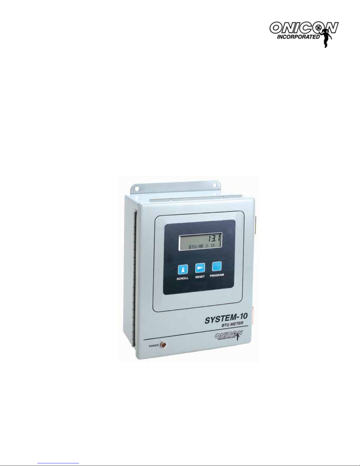
System-10 BTU Meter
LonWorks Network Interface Installation Guide
1500 North Belcher Road, Clearwater, FL 33765 • Tel (727) 447-6140 • Fax (727) 442-5699
0654-4 / 16751
www.onicon.com • sales@onicon.com
07-13
Page 2

1500 North Belcher Road, Clearwater, FL 33765 • Tel (727) 447-6140 • Fax (727) 442-5699 • sales@onicon.com
System-10-LON Network Interface Installation Guide 07/13 - 0654-4 / 16751 Page 2
Page 3

TABLE OF CONTENTS
1.0 INTRODUCTION ..................................................................................................5
1.1 PURPOSE OF THIS GUIDE .......................................................................5
1.2 TYPICAL SYSTEM-10 FLOW DISPLAY ...................................................5
1.3 SPECIFICATIONS ......................................................................................5
1.4 NETWORK SIGNAL CONNECTIONS .......................................................6
1.4.1 Lon Talk ...........................................................................................6
1.4.2 Optional Network Interface with
Isolated Digital Pulse Input (Di3) ................................................... 7
1.5 NETWORK ADDRESSING .......................................................................10
1.5.1 LonWorks Network Addressing ...................................................10
1.6 COMMISSIONING THE BTU METER ....................................................10
1.6.1 Service Pin LED States ..................................................................10
1.7 LONWORKS XIF FILES ...........................................................................10
1.7.1 Output Network Variables ............................................................10
1.7.2 Integer Format Output Network Variables ................................... 11
1.7.3 Input Network Variables ............................................................... 12
1.7.4 Node Object Network Variables ...................................................12
1.7.4.1 nviRequest ....................................................................... 12
1.7.4.2 nvoStatus ......................................................................... 13
1.7.5 Resetting Totals via the Network ..................................................13
1.7.6 Rollover of Totals ..........................................................................14
2.0 NETWORK TROUBLESHOOTING TIPS ...........................................................15
2.1 TROUBLESHOOTING .............................................................................15
APPENDIX A – DRAWINGS
A-1 BTU COMPUTER BOARD
A-2 SYSTEM-10-LON BTU METER LON BOARD
A-3 LON BOARD WITH DIGITAL INPUT PULSE (Di3)
A-4/A-5 INTEGER FORMAT OUTPUT NETWORK VARIABLES (2 PAGES)
A-6 LONWORKS TWISTED PAIR NETWORK TERMINATION
1500 North Belcher Road, Clearwater, FL 33765 • Tel (727) 447-6140 • Fax (727) 442-5699 • sales@onicon.com
System-10-LON Network Interface Installation Guide 07/13 - 0654-4 / 16751 Page 3
Page 4

1500 North Belcher Road, Clearwater, FL 33765 • Tel (727) 447-6140 • Fax (727) 442-5699 • sales@onicon.com
System-10-LON Network Interface Installation Guide 07/13 - 0654-4 / 16751 Page 4
Page 5

SECTION 1: INTRODUCTION
1.1 PURPOSE OF THIS GUIDE
The purpose of this guide is to provide installation and commissioning procedures and basic
operating and servicing instructions for the ONICON System-10 BTU Meter.
1.2 TYPICAL SYSTEM-10 BTU METER
ONICON’S System-10 is a true heat (Btu) computer which accepts data from several sensors,
performs a series of computations with that data, and displays and/or transmits the results as an
indication of the amount of heat (Btu’s) being transferred per unit time or as a totalized amount.
Local display of flow, temperature and
POWER
3864
SCROLL RESET PROGRAM
SYSTEM-10
BTU METER
ONICON
energy data
FLOW DIRECTION
flow meter purchased
24 VAC INPUT
Lon Talk
COMMUNICATIONS
TO NETWORK
ONICON insertion
separately
24 OR 120 VAC
Input Power
Individual Chiller
or Boiler
RETURN
SUPPLY
RETURN
TEMP
SENSOR
SUPPLY
TEMP
SENSOR
System
Mains
1.3 SPECIFICATIONS
LON TALK NETWORK INTERFACE
Twisted Pair / Free Topology
Transceiver: TP/FT-10F, 2-wire, non-polarized, transformer isolated connection
Device Address: 48-bit Neuron ID
Communications Rate: 78 kbps
Termination: None provided
Maximum Lead Length: 1640 ft (500m) free topology
1500 North Belcher Road, Clearwater, FL 33765 • Tel (727) 447-6140 • Fax (727) 442-5699 • sales@onicon.com
System-10-LON Network Interface Installation Guide 07/13 - 0654-4 / 16751 Page 5
Page 6

1.4 NETWORK SIGNAL CONNECTIONS
!
!
1.4.1 Lon Talk
Lon Talk, 2-wire serial output connections are connected to terminal T1 as shown. Do not
exceed 4.4 in-lb (0.5 Nm) of torque when tightening.
CAUTION
Only qualied service personnel should make connections between the System-10 BTU Meter
and the user’s external equipment. ONICON assumes no responsibility for damage caused to
the external equipment as a result of an improper installation.
Incoming and outgoing cable shield wires should be connected together, but must not be
connected to the System-10.
1500 North Belcher Road, Clearwater, FL 33765 • Tel (727) 447-6140 • Fax (727) 442-5699 • sales@onicon.com
System-10-LON Network Interface Installation Guide 07/13 - 0654-4 / 16751 Page 6
T1
CAUTION
Page 7

1.4.2 Optional Network Interface With Isolated Digital Pulse Input (Di3)
The System-10 BTU Meter can be provided with an auxiliary pulse input for totalizing
pulse outputs from external devices such as water or gas meters. Pulses are accumulated
in an internal register, and the totalized value is available on the network. This register
can be zeroed via the network. The maximum register total is 9,999,999. The register will
rollover to zero when this value is exceeded.
If the auxiliary pulse input option was ordered at the same time the Btu meter was
ordered, it will arrive fully congured and ready to use. If it was ordered after the Btu
meter was delivered and is being installed as a eld upgrade, it may be necessary to
congure the pulse input. The information is required to congure the input provided
below and on the following pages:
The input pulse must meet the following criteria:
1. Frequency input range, 50 Hz maximum
2. 10 millisecond minimum pulse duration
Input Pulse Denition:
In order to congure the communications card auxiliary pulse input, you must rst
determine which type of pulse your meter produces. The allowable types of input
pulses are described on the following pages. Based on the type of pulse, set the selector
switch (S1) on the communications circuit board (Fig. 1) to the correct setting.
Fig. 1
AUX PULSE INPUT (Di3)
CONNECTOR (T2)
1500 North Belcher Road, Clearwater, FL 33765 • Tel (727) 447-6140 • Fax (727) 442-5699 • sales@onicon.com
System-10-LON Network Interface Installation Guide 07/13 - 0654-4 / 16751 Page 7
Page 8

Powered Pulse:
This type of output refers to a pulse which has an associated voltage with it (see Fig. 2).
Set the selector switch, S1 to Pwrd Pulse. The allowable voltage range is 5-24 VDC. The
input impedance is set at the factory to be 11 KOHM via the impedance selector jumper
(J1, see Fig. 1). A lower impedance, 3 KOHM can be selected if required by the instrument
providing the pulse output. Consult the instrument manufacturer or ONICON if you are
uncertain as to the proper jumper selection.
Fig. 2
Di3 In (+)
Di3 In (-)
Open Collector (Sourcing):
This type of output refers to an open Collector Switch congured for a sourcing function
(see Fig. 3). Set the selector switch, S1 to SRC. The switch must be rated for at least 20mA
at 20VDC.
Fig. 3
Di3 In (+)
Di3 In (-)
1500 North Belcher Road, Clearwater, FL 33765 • Tel (727) 447-6140 • Fax (727) 442-5699 • sales@onicon.com
System-10-LON Network Interface Installation Guide 07/13 - 0654-4 / 16751 Page 8
Page 9

Open Collector Sinking or Dry Contact:
This type of output refers to an open collector switch congured in a current sinking
arrangement or a dry contact switch (see Fig. 4 and 5). Set the selector switch, S1 to Sink.
In either case, the switch must be rated for at least 20mA at 20 VDC.
Fig. 4
Di3 In (+)
Di3 In (-)
Fig. 5
Di3 In (+)
Di3 In (-)
1500 North Belcher Road, Clearwater, FL 33765 • Tel (727) 447-6140 • Fax (727) 442-5699 • sales@onicon.com
System-10-LON Network Interface Installation Guide 07/13 - 0654-4 / 16751 Page 9
Page 10

1.5 NETWORK ADDRESSING
The Btu meter contains two microprocessors, the heat computer board processor and the Echelon
TP/FT-10F transceiver with its Neuron processor. The TP/FT-10F transceiver is located on the
LON board. The two processors communicate with each other using a serial channel. This serial
channel device address is xed at 017 and cannot be changed.
1.5.1 LonWorks Network Addressing
Every Neuron processor has a unique 48 bit address kown as the Neuron ID. This address
is generally used as the Node ID. It is combined with the Domain ID and Subnet ID to form
the device address. In most installations, the device address is created dynamically by the
network.
1.6 COMMISSIONING THE SYSTEM-10-LON
Pressing the Service Pin on the LON board (see Appendix 2) generates a service pin message
on the network. The message contains the Neuron ID and the standard program identier
(SPID). The network conguration tool then maps the System-10-LON Neuron ID into the
domain/subnet/node ID addressing scheme for the network, creating the device address.
1.6.1 Service Pin LED States
The yellow service pin LED indicates the status of the Lon Talk network connection.
• LED blinking at ½ Hz rate indicates that the meter is in an decommissioned state.
• LED off indicates that the meter is commissioned and operating normally.
1.7 LONWORKS XIF FILES
Each System-10-LON BTU Meter is shipped with a diskette or CD containing the XIF le. It also
contains the Neuron executable le in various formats and documentation describing the
network variables in detail.
1.7.1 Output Network Variables
The System-10-LON BTU Meter transmits data to the network using Standard Network
Variable Types (SNVTs). Volume ow rate, and volume total are provided in oating point
format.
Display operating mode and mode status information is provided in ASCII character format.
The oating point output network variables are described in the table on the next page.
Column 1 contains a brief description of the network variables. Column 2 contains the
network variable names. Column 3 contains the Lon SNVTs used for each variable.
1500 North Belcher Road, Clearwater, FL 33765 • Tel (727) 447-6140 • Fax (727) 442-5699 • sales@onicon.com
System-10-LON Network Interface Installation Guide 07/13 - 0654-4 / 16751 Page 10
Page 11

FLOATING POINT OUTPUT NETWORK VARIABLES
Description Variable Name SNVT Name Engineering Units Valid Range
Flow (volume) rate nvoVolRateLf SNVT_ow_f Liters/Sec 0 to 10
Flow (volume) total -1 nvoVol1Lf SNVT_vol_f Liters 0 to 10
Flow (volume) total -2 nvoVol2Lf SNVT_vol_f Liters 0 to 10
Supply temperature nvoSupplyTempf SNVT_temp_f ° C -17.778 to 148.889
Return temperature nvoReturnTempf SNVT_temp_f ° C -17.778 to 148.889
Energy rate nvoEnrRateWf SNVT_power_f Watts 0 to 10
*Displayed energy rate nvoDispEnrRatef SNVT_count_f *See note 0 to 10
Energy total -1 nvoBTU1f SNVT_BTU_f Btu 0 to 10
*Displayed energy total-1 nvoDispEnergy1f SNVT_count_f *See note 0 to 10
Energy total-2 nvoBTU2f SNVT_BTU_f Btu 0 to 10
*Displayed energy total-2 nvoDispEnergy2f SNVT_count_f *See note 0 to 10
Auxiliary pulse input (Di3) nvoAuxIn1 SNVT_count_f None 0 to 10
* These network variables transmit energy rate and total data exactly as it is displayed on the
System-10 front panel display. The value transmitted will not include any multiplier associated
with displayed total.
12
12
12
12
12
12
12
12
12
12
The ASCII character status output network variables are described in the table below.
Column 1 contains a brief description of the network variables. Column 2 contains the
network variable names. Column 3 contains the Lon SNVT used for each variable.
Column 4 contains the ASCII single characters that may be transmitted by the meter
along with a description of what they indicate.
ASCII STATUS OUTPUT NETWORK VARIABLES
Description Variable Name SNVT Name Valid ASCII Characters*
Meter operating
mode indicator
nvoMeterMode SNVT_char_ascii
S = Single mode (83)
D = Dual mode (68)
B = Bidirectional mode (66)
N = Communication lost (78)
Z = Communication restored waiting for
Mode status
indicator
nvoModeStatus SNVT_char_ascii
update (90)
H = Heating mode (mode 1) (72)
C = Cooling mode (mode 2) (67)
F = Forward ow (mode 1) (70)
R = Reverse ow (mode 2) (82)
* Systems that are not set to decode ASCII characters will display the decimal equivalent.
These values are shown in parentheses.
1.7.2 Integer Format Output Network Variables
ONICON provides rate and total data to the network in integer format for systems that
cannot accept the oating point data. Refer to Appendices 4 and 5 for information on the
use of integer format SNVTs.
1500 North Belcher Road, Clearwater, FL 33765 • Tel (727) 447-6140 • Fax (727) 442-5699 • sales@onicon.com
System-10-LON Network Interface Installation Guide 07/13 - 0654-4 / 16751 Page 11
Page 12

1.7.3 Input Network Variables
The System-10-LON BTU Meter receives remote commands to reset totals from the
network using Standard Network Variable Types (SNVTs). The input network variables are
in ASCII format. They are used to zero the ow, energy and auxiliary pulse totals
transmitted in the output variables listed in section 1.7.1.
The ASCII character reset input network variables are described in the table below.
Column 1 contains a brief description of the network variables. Column 2 contains the
network variable names. Column 3 contains the Lon SNVT used for each variable. Column
4 contains the ASCII single characters that must be transmitted to the meter along with a
description of what they indicate.
ASCII RESET INPUT VARIABLES
Description Variable Name SNVT Name Valid Characters*
Reset Energy-1 nviResetBTU1a SNVT_char_ascii
Reset Volume-1 nviResetVol1a SNVT_char_ascii
Reset Energy-2 nviResetBTU2a SNVT_char_ascii
Reset Volume-2 nnviResetVol2a SNVT_char_ascii
Write an ASCII 1 (49) to reset the
selected total. Once the total has
reset, change the value to back to
ASCII 0 (48).
Reset Auxin1 (Di3) nviResetAuxIn1a SNVT_char_ascii
*Systems that are not set to decode ASCII characters will use and display the decimal
equivalent. These values are shown in parentheses.
1.7.4 Node Object Network Variables
The System-10 LON BTU Meter node object utilizes one output network variable and one
input network variable. These are described in the table below.
NODE OBJECT NETWORK VARIABLES
Description Variable Name SNVT Name
Node object control input nviRequest SNVT_obj_request
Node object response output nvoStatus SNVT_obj_status
1.7.4.1 nviRequest
Five input variable requests have been implemented. These are listed in the table
on the next page. Three of the requests are mandatory functions. They are
Normal, Update Mask and Report Mask. The other two are used to reset totals in
the Btu meter. They are Reset and Clear Reset.
The requests can be used on the node object or on selected function blocks. The
tables on the next page describe the requests and the function blocks associated
with totals in the Btu meter.
1500 North Belcher Road, Clearwater, FL 33765 • Tel (727) 447-6140 • Fax (727) 442-5699 • sales@onicon.com
System-10-LON Network Interface Installation Guide 07/13 - 0654-4 / 16751 Page 12
Page 13

NODE OBJECT REQUESTS
Node Object
Requests
Function
Blocks
Affected
Comments
RQ_NORMAL 0-27 This request clears the status registers. Function block 0 clears
all function block status registers. Selecting function blocks 1- 27
only clears the selected status register.
RQ_UPDATE_MASK 0-27 This request updates the selected status register.
RQ_REPORT_MASK 0-27 This request displays the available Object Status functions.
RQ_RESET 0, 3, 6, 17,
21, 27
This request zeroes the various ow, energy and auxiliary pulse
totals. If the Object ID 0 request RQ_RESET is selected then all
totals are cleared. If the Object ID of 3, 6, 17, 21 or 27 RQ_RESET
is selected then only the appropriate total is cleared.
RQ_CLEAR_RESET 0, 3, 6, 17,
21, 27
This request clears reset status ags. Object ID of 0 clears all
“reset_complete” ags. Object IDs 3, 6, 17, 21, 27: Clears the
selected “reset_complete” ags.
SELECT FUNCTION BLOCKS, BTU METER TOTALS & BTU METER OPERATING MODES
Functional
Block
3 Flow (volume) - 1 Heat or Cool Heating Forward Flow
6 Flow (volume) - 2 Inactive Cooling Reverse Flow
17 Energy-1 Heat or Cool Heating Forward Flow
21 Energy-2 Inactive Cooling Reverse Flow
27 Auxiliary Pulse (Di3) Active Active Active
Btu Meter Total
Single Dual Bidirectional
Btu Meter Operating Mode
1.7.4.2 nvoStatus
Six status object functions are mechanized to report status information to
the network. These are listed in the table below. The table also lists
function blocks associated with each status ag.
nvoStatus Object Functions Functional Blocks
object_id All
invalid_id All
invalid_request All
comm_failure 0
report_mask All
reset_complete 0, 3, 6, 17, 21, 27
1.7.5 Resetting Totals via the Network
Totals are held in non-volatile memory within the Btu meter. Each total (ow, energy or
auxiliary input) has a corresponding output variable that transmits the information from
the meter to the network. There are two ways to remotely reset totals in the display. This
can be done using individual input variables to command the display to reset specic
totals or it can be done using the nviRequest variable. Using nviRequest allows you to
reset each total individually or all totals simultaneously with one command. See sections
1.7.3 and 1.7.4.1 for specic instructions on how to reset totals.
1500 North Belcher Road, Clearwater, FL 33765 • Tel (727) 447-6140 • Fax (727) 442-5699 • sales@onicon.com
System-10-LON Network Interface Installation Guide 07/13 - 0654-4 / 16751 Page 13
Page 14

1.7.6 Rollover of Totals
The totals stored in the ow Btu meter memory will roll over to zero when the maximum
count is exceeded. When this occurs, the network totals will also roll over to zero. The
point at which the rollover occurs is a function of the displayed engineering units and
multipliers programmed into the System-10.
The examples below show the rollover point in the engineering units transmitted by the
network variable (SNVT) for common totals shown on the System-10-LON BTU Meter.
VOLUME TOTAL
System-10 BTU Meter
Engineering Units
Gallons X 100 SNVT_vol_f – Liters 3,785,411,621 Liters
Liters X 1000 SNVT_vol_f – Liters 9,999,999,000 Liters
M³ X 1 SNVT_vol_f – Liters 9,999,999,000 Liters
ENERGY TOTAL
System-10 BTU Meter
Engineering Units
Btu X 10k SNVT_Btu_f – Btu 99,999,990,000 Btu
kWhr X 10 SNVT_Btu_f – Btu 341,214,065,900 Btu
Tonhr X 1 SNVT_Btu_f – Btu 119,999,998,000 Btu
System-10 BTU
Meter
Multiplier
System-10 BTU
Meter
Multiplier
LonWorks SNVT and
Transmitted
Engineering Units
LonWorks SNVT and
Transmitted
Engineering Units
Maximum Total Transmitted
Over the Network
Maximum Total Transmitted
Over the Network
1500 North Belcher Road, Clearwater, FL 33765 • Tel (727) 447-6140 • Fax (727) 442-5699 • sales@onicon.com
System-10-LON Network Interface Installation Guide 07/13 - 0654-4 / 16751 Page 14
Page 15

SECTION 2.0: NETWORK TROUBLESHOOTING TIPS
2.1 TROUBLESHOOTING
REPORTED PROBLEM POSSIBLE SOLUTIONS
For turbine meters No Flow Signal/ Energy Rate
(while hydronic system is
active)
Displayed ow rate too high
or too low
Displayed temperature(s) too
high or too low vs. expected
values
Device is not communicating
with the Lon Talk network.
• Verify 24 VDC supply voltage to the ow meter.
• For insertion meters, verify the ow meter is correctly inserted
into the pipe (using depth gage).
• For insertion meters, verify that the ow meter electronics
enclosure is parallel with the pipe.
• Verify correct wiring to the ow meter (see wiring diagram).
• For turbine meters, check turbine(s) for clogging due to debris.
• If none of the above, check hydronic system to ensure that ow is
really present in the line.
• NOTE: Flow meter function cannot be veried by blowing on the
turbine(s). The sensing system requires a conductive liquid to
operate. You can test it by swirling it around in a bucket of water
and looking for the ow indicator LED to ash at the System-10.
• Verify pipe size. Contact ONICON if pipe size is different from
calibration tag.
• For insertion meters, verify that meter is inserted correctly into the
pipe (using depth gage).
• For insertion meters, verify that the ow meter electronics
enclosure is parallel with the pipe.
• For dual turbine meters, conrm that both turbines produce
pulses.
• For turbine meters, check turbine(s) for debris.
• Verify supply voltages (to Btu meter and ow meter).
• Verify wiring to temperature sensor(s), including polarity.
• Verify that thermowells are inserted into the ow stream and
that the temperature sensors are completely inserted into the
thermowells.
• What is the state of the service pin LED?
• Is it ashing? A ashing service pin LED indicates that the Lon
module has not been commissioned.
Communications with
the Lon Talk network is
intermittent.
For technical assistance, contact ONICON at (727) 447-6140.
1500 North Belcher Road, Clearwater, FL 33765 • Tel (727) 447-6140 • Fax (727) 442-5699 • sales@onicon.com
System-10-LON Network Interface Installation Guide 07/13 - 0654-4 / 16751 Page 15
• Is it off? A service pin LED that is off indicates that the Lon
module is commissioned and operating normally.
• Is the network properly terminated? The Lon TP/FT bus can be
terminated in 2 different ways.
• A single RC lter can installed at any point on a free topology
network. A dual termination scheme is used with 2 RC lters
installed at the ends of bus networks. Refer to the Appendix A-6
for details.
• What type of cable is used to wire the network? TP/FT networks
should only use twisted shielded pair cable. (Belden 85102 or
equiv.)
Page 16

APPENDIX A – DRAWINGS
A-1 BTU COMPUTER BOARD
A-2 SYSTEM-10-LON BTU METER LON BOARD
A-3/A-4 INTEGER FORMAT OUTPUT NETWORK VARIABLES (2 PAGES)
A-5 LONWORKS TWISTED PAIR NETWORK TERMINATION
1500 North Belcher Road, Clearwater, FL 33765 • Tel (727) 447-6140 • Fax (727) 442-5699 • sales@onicon.com
System-10-LON Network Interface Installation Guide 07/13 - 0654-4 / 16751 Page 16
Page 17

SYSTEM-10 BTU METER COMPUTER BOARD
Reset
Temp Test
Prog Mode
Enable
Device Address
Program Enable
Serial Comm
1500 North Belcher Road, Clearwater, FL 33765 • Tel (727) 447-6140 • Fax (727) 442-5699 • sales@onicon.com
System-10-LON Network Interface Installation Guide 07/13 - 0654-4 / 16751 Page A-1
Page 18

SYSTEM-10-LON BTU METER LON BOARD
1500 North Belcher Road, Clearwater, FL 33765 • Tel (727) 447-6140 • Fax (727) 442-5699 • sales@onicon.com
System-10-LON Network Interface Installation Guide 07/13 - 0654-4 / 16751 Page A-2
Page 19

INTEGER FORMAT OUTPUT NETWORK VARIABLES
Integer format output variables are limited to 2 bytes of data. For this reason, the maximum number that
can be transmitted in this format is 65,535. Values for both rate and total data from the Btu meter will often
exceed this limit. For this reason, energy rate data is scaled and energy totals are transmitted in segments
using multiple variables. This is explained in detail below.
Volume and Energy Rate Variables
The integer output network variables for volume and energy rate are described in the table below. Column
1 contains a brief description of the network variables. Column 2 contains the network variable names.
Column 3 contains the Lon SNVTs used for each variable. Column 4 contains the engineering units and
column 5, the valid range for each variable. Please note that while the oating point variable for energy
rate is transmitted in Watts, the integer network variable is transmitted in kW to ensure that the maximum
rate never exceeds the register capacity.
Integer Output Network Variables
Description Variable Name SNVT Name Engineering Units Valid Range
Flow (volume) rate nvoVolRateLi SNVT_ow Liters/Sec 0 to 65535
Mode status indicator nvoModeStatus SNVT_char_ascii
Supply temperature nvoSupplyTempi SNVT_temp_p ° C -17.778 to 260.0
Return temperature nvoReturnTempi SNVT_temp_p ° C -17.778 to 260.0
Delta temperature nvoDeltaTempi SNVT_temp_diff_p ° C -327.68 to 327.66
Energy rate nvoEnrRateKWi SNVT_power_kilo KWatts 0 to 65535
Volume and Energy Total Variables
The integer output network variables for volume and energy total are described in the table below. Column
1 contains a brief description of the network variables. Column 2 contains the network variable names.
Column 3 contains the Lon SNVTs used for each variable. Column 4 contains the engineering units and
column 5, the valid range for each variable.
Please note that while the oating point variable for volume total is transmitted in liters, the integer
network variable for volume total is transmitted in kLiters. This is done to increase the maximum total
that can be transmitted via the integer variable. Total(s) must be reset before the accumulated value
exceeds 6553.5 kliters using nviResetVol1a and/or nviResetVol2a. If this is not done, nvoVol1KLi and/or
nvoVol2KLi will over range and continue to indicate 6,553.5 kliters (1,731,252 gallons) until the
System-10’s internal total rolls over to zero.
A separate integer SNVT is also available to transmit ow totals in liters. This variable is only used in
special small pipe applications as the maximum total it can accumulate is only 65,535 liters (17,312
gallons) before it must be reset.
Energy totals are handled in a slightly different way. The oating point variable for energy total is
transmitted in Btu but the integer network variable for energy total is MBtu. This total will over range at
65,535 MBtu. The internal total stored in the Btu meter will not roll over until it exceeds 99,999.99 MBtu.
1500 North Belcher Road, Clearwater, FL 33765 • Tel (727) 447-6140 • Fax (727) 442-5699 • sales@onicon.com
System-10-LON Network Interface Installation Guide 07/13 - 0654-4 / 16751 Page A-3
Page 20

INTEGER FORMAT OUTPUT NETWORK VARIABLES
(continued)
In order to prevent the loss of data nvoMegaBTU1i and/or nvoMegaBTU2i must be reset before the
accumulated value exceeds 65,535 MBtu.
A second variable is available for energy totals. It is kBtu. This variable will roll over to zero whenever
the accumulated value exceeds 65,535 kBtu. This variable has been provided to accommodate small pipe
applications where MBtu is not appropriate. The two energy variables (MBtu and KBtu) can be combined
to produce a total with resolution to 1000 Btu (1kBtu). Programming for this calculation is given below.
Integer Output Network Variables
Description Variable Name SNVT Name Engineering Units Valid Range
* Flow (volume) total -1 nvoVol1Li SNVT_vol Liters 0 to 65535
Flow (volume) total -1 nvoVol1KLi SNVT_vol KLiters 0 to 6553.5
* Flow (volume) total -2 nvoVol2Li SNVT_vol Liters 0 to 65535
Flow (volume) total -2 nvoVol2KLi SNVT_vol KLiters 0 to 6553.5
Energy total -1 nvoKiloBTU1i SNVT_btu_kilo KBtu 0 to 65535
Energy total -1 nvoMegaBTU1i SNVT_btu_mega MBtu 0 to 65535
Energy total -2 nvoKiloBTU2i SNVT_btu_kilo KBtu 0 to 65535
Energy total -2 nvoMegaBTU2i SNVT_btu_mega MBtu 0 to 65535
* Special small pipe volume total variables
Totalizing Using Both the MBtu and KBtu Variables Combined
MBtu (Btu x 1,000,000) is value in nvoMegaBTU1i (or nvoMegaBTU2i)
KBtu (Btu x 1,000,000) is value in nvoKiloBTU1i (or nvoKiloBTU2i)
Combined total = MBtu x 1000 + X
Where X = KBtu - [int (KBtu/1000) x 1000]
Example:
nvoMEGABTU1i present value = 4006 MBtu
nvoKILOBTU!i present value = 6200 KBtu
Combined total = (4006 x 1000) + (6200 - [int(6200/1000) x 1000])
Combined total = 4006000 + (6200 - 6000)
Combined total = 4006200 KBtu
1500 North Belcher Road, Clearwater, FL 33765 • Tel (727) 447-6140 • Fax (727) 442-5699 • sales@onicon.com
System-10-LON Network Interface Installation Guide 07/13 - 0654-4 / 16751 Page A-4
Page 21

LONWORKS TWISTED PAIR NETWORK TERMINATION
LonWorks Twisted Pair Network Termination
(Recommended Cable: Belden 85102 or equiv.)
Free Topology Network (Single Termination)
C1
100 uf electrolytic
+
R1
52.3 Ohm
+
C2
100 uf electrolytic
Connect across Lon
bus at any point.
Bus Network (Dual Termination)
C1
100 uf electrolytic
+
R1
105 Ohm
Connect across Lon network
at each end of the bus.
+
C2
100 uf electrolytic
1500 North Belcher Road, Clearwater, FL 33765 • Tel (727) 447-6140 • Fax (727) 442-5699 • sales@onicon.com
System-10-LON Network Interface Installation Guide 07/13 - 0654-4 / 16751 Page A-5
 Loading...