

Page 1
FT-3100 Transmitter
Inline Electromagnetic Flow Meter
Programming Guide
ONICON
Flow and Energy Measurement
Page 2

TABLE OF CONTENTS
1.0 INTRODUCTION .........................................................................................................................5
1.1 Purpose of this Guide ...................................................................................................................................... 5
1.2 Display and User Interface ............................................................................................................................. 5
1.3 Accessing the Programming Menus .......................................................................................................... 6
2.0 QUICK START MENU ..................................................................................................................6
2.1 MENU - QUICK START ..................................................................................................................................... 7
Empty Pipe Detector [E.P.Detect=ON] .................................................................................................... 7
Empty Pipe Threshold [R max=kohm XXXX] ......................................................................................... 7
Scaled Pulse Output 2 [Pls2=Gal X.XXXX] ............................................................................................. 7
Output 2 Pulse Duration [Tpls2=ms X.XXXX] ........................................................................................ 8
Analog Output 1 Full Scale Value [A1S=Gal/m XXXXXX] ................................................................. 8
3.0 MAIN MENU ............................................................................................................................... 9
3.1 MENU 1 - SENSOR ............................................................................................................................................ 9
Sensor Body Model [S.Model=XXX] ......................................................................................................... 9
Liner Material [Lining=XXXXXX] ...............................................................................................................10
Unit Type [U.type=XXXXXX] .......................................................................................................................10
Diameter [Diam.=XXX] .................................................................................................................................10
KA [KA=±XX.XXX] ..........................................................................................................................................10
KZ [KZ=±XXXX] ..............................................................................................................................................10
Empty Pipe Detector [E.P.Detect=ON] ..................................................................................................11
Empty Pipe Threshold [R max=kohm XXXX] .......................................................................................11
Electrode Cleaning [El. Cleaning=MIN] .................................................................................................11
Sensor Cable Length [S.cable=ft XXX] ...................................................................................................12
Alarm Delay Interval [S.err.delay=m XXX] ............................................................................................12
FT-3100 TRANSMITTER PROGRAMMING GUIDE
3.2 MENU 2 - UNITS .............................................................................................................................................13
Diameter Unit Type [Diam.=in] .................................................................................................................13
Remote Mount Cable Unit Type [S.cable=ft] ......................................................................................13
Flow Rate Unit Type [FR unit=IMPERIAL] .............................................................................................13
Pulse 1 Unit Type [Pl1 unit=IMPERIAL] ..................................................................................................14
Pulse 2 Unit Type [Pl2 unit=IMPERIAL] ...................................................................................................14
Total Forward Flow Totalizer Unit Type [T+ unit=IMPERIAL] ..........................................................14
Total Forward Flow Totalizer Units [T+ unit=Gal] ...............................................................................14
Total Forward Flow Totalizer Decimal Point Position [T+ D.P.=X] ................................................14
Partial Forward Flow Totalizer Unit Type [P+ unit=IMPERIAL] .......................................................14
Partial Forward Flow Totalizer Units [P+ unit=Gal] ............................................................................15
Partial Forward Flow Totalizer Decimal Point Position [P+ D.P.=X] .............................................15
Total Reverse Flow Totalizer Unit Type [T- unit=IMPERIAL] ............................................................15
Total Reverse Flow Totalizer Units [T- unit=Gal] .................................................................................15
Total Reverse Flow Totalizer Decimal Point Positiion [T- D.P.=X] .................................................15
Partial Reverse Flow Totalizer Unit Type [P- unit=IMPERIAL] .........................................................15
Partial Reverse Flow Totalizer Units [P- unit=Gal] ..............................................................................15
Partial Reverse Flow Totalizer Decimal Point Position [P- D.P.=X] ...............................................16
Temperature Unit Type [Temp. unit= °F] ................................................................................................ 16
Mass Units Enable [Mass units=OFF] ......................................................................................................16
Specic Gravity Coecient [Sg=kg/dm3 X.XXXX] ..............................................................................16
ONICON Incorporated 727.447.6140 Page 2 onicon.com
Page 3

FT-3100 TRANSMITTER PROGRAMMING GUIDE
3.3 MENU 3 - SCALES ...........................................................................................................................................17
Full Scale Flow Rate 1 [FS1= Gal/m XXX.X] ...........................................................................................17
Full Scale Flow Rate 2 [FS2 = Gal/m XXX.X] ..........................................................................................18
Scaled Pulse Output 1 [Pls1 = Gal X.XXXX] ...........................................................................................18
Output 1 Pulse Duration [Tpls1 = ms X.XXXX] .....................................................................................19
Output 1 Full Scale Frequency [Frq1 = Hz X.XXXXX] ........................................................................19
Scaled Pulse Output 2 [Pls2 = Gal X.XXXX] ...........................................................................................19
Output 2 Pulse Duration [Tpls2 = ms X.XXXX] .....................................................................................20
Output 2 Full Scale Frequency [Frq2 = Hz X.XXXXX] ........................................................................20
3.4 MENU 4 - MEASURE.......................................................................................................................................21
Flow Signal Damping [Damping=SMART] ............................................................................................21
Low Flow Cut-o [Cut-o = % XXX] ........................................................................................................22
Autorange [Autorange=OFF]......................................................................................................................22
High Immunity Input Filter [H.im.imp.=OFF] ........................................................................................22
3.5 MENU 5 - ALARMS ........................................................................................................................................23
Maximum Forward Flow Alarm Threshold [Max+ = Gal/m OFF] ................................................23
Maximum Reverse Flow Alarm Threshold [Max - = Gal/m OFF] .................................................23
Minimum Forward Flow Alarm Threshold [Min + = Gal/m OFF] ................................................23
Minimum Reverse Flow Alarm Threshold [Min - = Gal/m OFF] ..................................................24
Alarm Hysteresis Threshold [Hysteresis=%XXX] ................................................................................24
mA Output Value When in Alarm State [mA v.alarm=%XXX] .......................................................24
Frequency Output Value When in Alarm State [Hz v.alarm = %XXX} ........................................25
3.6 MENU 6 - INPUTS...........................................................................................................................................26
Total Forward Flow Totalizer Reset Enable [T+reset=ON] .............................................................26
Partial Forward Flow Totalizer Reset Enable [P+reset=OFF] .........................................................26
Total Reverse Flow Totalizer Reset Enable [T-reset=OFF] ...............................................................26
Partial Reverse Flow Totalizer Reset Enable [P-reset=OFF] ............................................................26
Disable Totalizers via Pulse Input [Meas. Lock=OFF] ....................................................................... 26
Activate Autozero Calibration via Pulse Input [Calibration=OFF] ...............................................27
Change Flow Range via Pulse Input [Range change=OFF] ...........................................................27
3.7 MENU 7 - OUTPUTS ......................................................................................................................................28
Digital Output 1 Function Select [Out1=XXXXXX] ............................................................................28
Digital Output 2 Function Select [Out2=XXXXXX] ............................................................................28
mA Output 1 Function & Scaling [Out mA1=4_20+/-] ...................................................................29
Analog Output 1 Full Scale Value [A1S=Gal/m XXXXXX] ...............................................................29
3.8 MENU 9 - DISPLAY .........................................................................................................................................30
Display Language [Language=GB] ..........................................................................................................30
Contrast Adjustment [Contrast=X] .........................................................................................................30
Display/User Interface Inactivity Time Interval [Disp. times=sXXX] ...........................................30
Display Refresh Frequency [D.rate=Hz X].............................................................................................30
Display Lock [Disp. lock=OFF]...................................................................................................................31
Enable Partial Totalizers [Part. tot.=OFF] ...............................................................................................31
Enable Negative Totalizers [Neg. tot. = OFF] ....................................................................................... 31
Enable Net Totalizers [Net tot.=OFF] .....................................................................................................32
Enable Quick Start Menu [Quick start=ON] ........................................................................................32
Default Display Page [Disp. fn = X] ..........................................................................................................33
ONICON Incorporated 727.447.6140 Page 3 onicon.com
Page 4

FT-3100 TRANSMITTER PROGRAMMING GUIDE
3.9 MENU 11 - FUNCTIONS ..............................................................................................................................34
Reset Total Forward (+) Totalizer [T + reset] .......................................................................................34
Reset Partial Forward (+) Totalizer [P + reset] ....................................................................................34
Reset Total Reverse (-) Totalizer [T - reset] ........................................................................................... 34
Reset Partial Reverse (-) Totalizer [P - reset] ........................................................................................34
Load Factory Default Sensor Body Settings [Load sens.f.def] ......................................................34
Load Factory Default Transmitter Settings [Load Conv.f.def] .......................................................34
3.10 MENU 12 - DIAGNOSTIC ............................................................................................................................35
Self Diagnostic Test [Self test] ................................................................................................................... 35
Test Display [Display test] ........................................................................................................................... 35
Simulate Flow Rate [Flow sim. = OFF] ...................................................................................................35
Firmware Information [Firmware info] ...................................................................................................35
Serial Number [S/N = XXXXXX] ................................................................................................................35
Working Time [WT = XXXX:XX:XX:XX] ...................................................................................................35
ONICON Incorporated 727.447.6140 Page 4 onicon.com
Page 5
SECTION 1.0: INTRODUCTION
FT-3100 TRANSMITTER PROGRAMMING GUIDE
1.1 PURPOSE OF THIS GUIDE
1.2 DISPLAY AND USER INTERFACE
Gal/m
2 ALARM(S)
ONICON
Flow and Energy Measurement
+0.00
SHORT PUSH LONG PUSH
The purpose of this guide is to provide programming information for the FT-3100
transmitter congured with the following options:
• One (1) analog output
• Two (2) digital outputs
• One (1) digital input
It does not include information on serial communications or data logging.
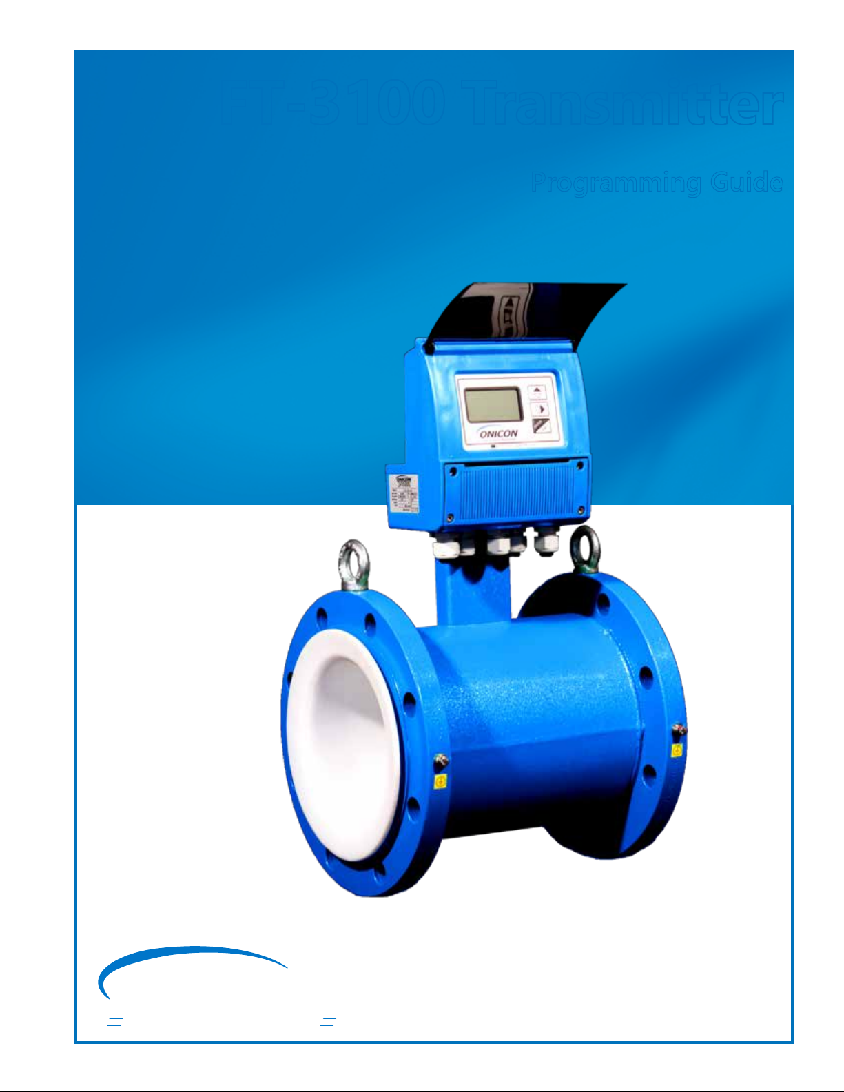
The FT-3100 transmitter is equipped with a lighted graphic display and 3-button
user interface as shown below.
0
Briefly press the middle button to advance
to the next menu page.
ENTER
ESC
The ENTER button is used in programming.
STATUS ICONS
Icon Description Icon Description
Empty Pipe Signal Error
Low Flow Alarm Excitation Error
High Flow Alarm General Alarm (Flashing)
Flow Rate Overow Flow Rate Simulation (Flashing)
Pulse 1 Overow Pulse 2 Overow
Generic Alarm (Flashing) Calibration (Flashing)
A multicolored LED inside the eld wiring compartment provides
addition information on the operating status.
Red LED: Alarm
Blue LED: USB comm enabled
Green LED: Normal Operation
ONICON Incorporated 727.447.6140 Page 5 onicon.com
Page 6
FT-3100 TRANSMITTER PROGRAMMING GUIDE
ACCESS CODE
Code : 4
999999990
*******
QUICK START
E. P. Detect=
R max=kohm
Pls2=Gal
Tpls2=ms
A1S=Gal/m
Main Menu
ON
0220
1000.0
0500.0
004500
2 ALARM(S)
0
+0.00
Gal/m
1.3 ACCESSING THE
PROGRAMMING MENUS
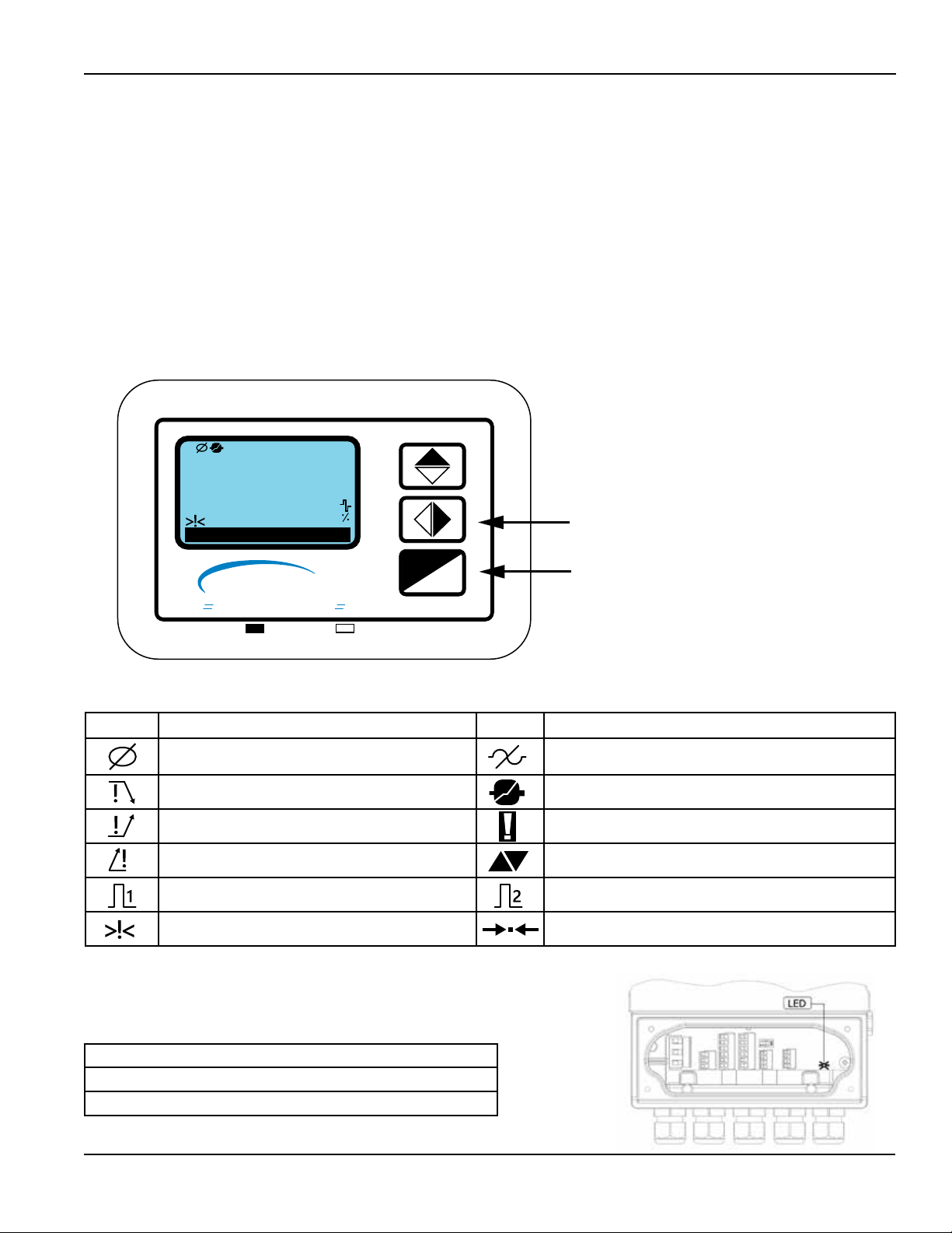
Access to the programming menus is password protected. The factory default
access code is 4********. The three user interface push-button functions described
below change when operating in the program mode.
Push Button Short Press
(<1 second)
• Increments the numeric value or selected
parameter
• Returns to the previous menu item
• Moves the cursor to the right on input elds
• Advances to the next menu item
• Changes the process data display
• Enters or leaves the selected function
ENTER
ESC
SECTION 2.0:
QUICK START MENU
• Enters the program mode
• Cancels the selected function in progress
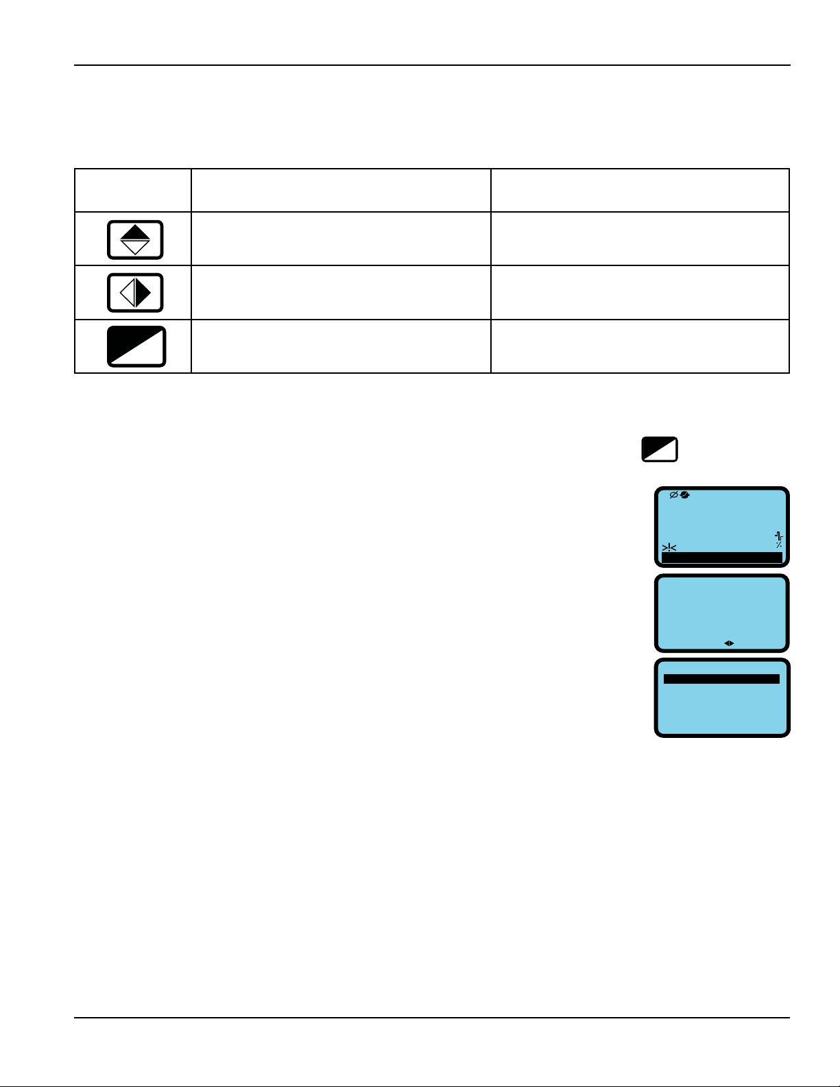
The most commonly used programming functions are available in the Quick Start
menu. The menu can be accessed by briey pressing the
the access code 4*******. Additional programming options are accessed via the
Main Menu.
Long Press
(>1 second)
• Decrements the numeric value
• Advances to the next menu item
• Moves the cursor to the left on input elds
• Returns to the previous menu item
• Exits the current menu
• Conrms the selected function to enable the
totalizer reset request, when enabled.
key and entering
ENTER
ESC
1. From the main screen, quickly press the
Enter key.
2. Enter the access code.
3. Enter into the Quick Start menu.
ONICON Incorporated 727.447.6140 Page 6 onicon.com
Page 7

FT-3100 TRANSMITTER PROGRAMMING GUIDE
2.1 MENU - QUICK START
Empty Pipe Detector
[E.P.Detect = ON]
Empty Pipe Threshold
[R max = kohm XXXX]
Empty Pipe Detector [E.P.Detect = ON]
Empty Pipe Threshold [R max = kohm XXXX]
Scaled Pulse Out 2 Volume [Pls2 = Gal XXX.XXX]
Output 2 Pulse Duration [Tpls2 = XXXX.X]
Analog Output 1 Full Scale Value [A1S = Gal/m XXXXXX]
MAIN MENU
This setting enables or disables the empty pipe detector.
The Empty Pipe Detector senses when uid is drained from the pipe and the ow
sensing electrodes are exposed to air. When this occurs, the displayed ow rate
will drop to zero and the empty pipe icon will be displayed in the upper lefthand side of the display window. If the current (mA) output alarm is active, the
milliamp output will also indicate an alarm condition.
To change the existing setting, press enter to access the function and use the up
arrow key to turn the function on or o. Press enter to accept the change and
exit the function. Press escape to exit the program mode. Table of Contents
The empty pipe threshold function is used to set the maximum allowable
resistance value between the ow sensing electrodes in the transmitter. The
transmitter will go into empty pipe alarm when the value is exceeded. The default
value is 500. The maximum allowable value is 9,999.
Scaled Pulse Output 2
[Pls2 = Gal X.XXXX]
To enter a new value, press enter to access the function. Use the right arrow key
to move the cursor and the up arrow key to change the resistance. Press enter to
accept the change and exit the function. Press escape to exit the program mode.
Table of Contents
This function is only available when output pulse 2 in OUTPUTS menu (menu 7)
[Out2 = XXXXX] is set to Pulses+, Pulses- or Pulses±. When active, Scaled Output
Pulse 2 sets the unit of measure and the volume or mass that equates to one
pulse. This pulse weight setting is limited by the diameter of the ow sensor.
The list of units of measure available for selection can be in US/IMPERIAL or SI
units depending on the pulse 2 unit type [Pl2 unit = IMPERIAL] setting in UNITS
menu (menu 2). In the same way, the list will show mass units, if mass units are
enabled [Mass units = OFF] in menu 2. The tables below show the available units
of measure.
ONICON Incorporated 727.447.6140 Page 7 onicon.com
Page 8

FT-3100 TRANSMITTER PROGRAMMING GUIDE
US/IMPERIAL Volume Units
3
in
Cubic Inch
Gal US Gallon
ttG US Gallon x 10,000
3
ft
Cubic Foot
bbl Standard Barrel
BBL Barrel of Oil
3
hf
Kf
3
Cubic Foot x 100
Cubic Foot x 1,000
KGL US Gallon x 1,000
IGL Imperial Gallon
IKG Imperial Gallon x 1,000
Aft Acre Foot
MGL Mega Gallon (US)
IMG Imperial Mega Gallon
SI/METRIC Volume Units
3
cm
Cubic Centimeter
ml Mililiter
l Liter
3
dm
Cubic Decimeter
dal Decaliter
hl Hectoliter
3
m
Cubic Meter
ML Megaliter
US/IMPERIAL Mass Units
Oz Ounce
Lb Pound
Ton Short Ton (2,000 lbs)
SI/METRIC Mass Units
g Gram
kg Kilogram
t Metric Ton (1,000 kg)
Output 2 Pulse Duration
[Tpls2 = ms X.XXXX]
Analog Output 1 Full
Scale Value
[A1S = Gal/m XXXXXX]
To enter a new value, press enter to access the function and use the right arrow
key to move the cursor and the up arrow key to change the entry. Press enter to
accept the change and exit the function. Press escape to exit the program mode.
Table of Contents
Output 2 pulse duration is only active when scaled pulse output 2 [Pls2= Gal
X.XXXX] is active. It is used to set the duration of each pulse. The duration is set
in milliseconds with a range of 0.4 to 9999.99.
Note: Pulse durations must match the requirements of the input they are
connected to. Very short pulse times may not be counted by the input and long
duration pulsed may damage electromechanical registers.
To enter a new value, press enter to access the function. Use the right arrow
key to move the cursor and the up arrow key to change the pulse duration.
Press enter to accept the change and exit the function. Press escape to exit the
program mode. Table of Contents
This function sets the full scale ow value for the analog output.
The maximum allowable ow rate is a function of the diameter of the ow sensor.
Regardless of the diameter, the maximum ow rate setting cannot exceed a
velocity of 10 m/s.
To enter a new value, press enter to access the function. Use the right arrow key
to move the cursor and the up arrow key to change the value. Press enter to
accept changes and exit the function. Press escape to exit the program mode.
Table of Contents
ONICON Incorporated 727.447.6140 Page 8 onicon.com
Page 9
FT-3100 TRANSMITTER PROGRAMMING GUIDE
SECTION 3.0: MAIN MENU
3.1 MENU 1 - SENSOR
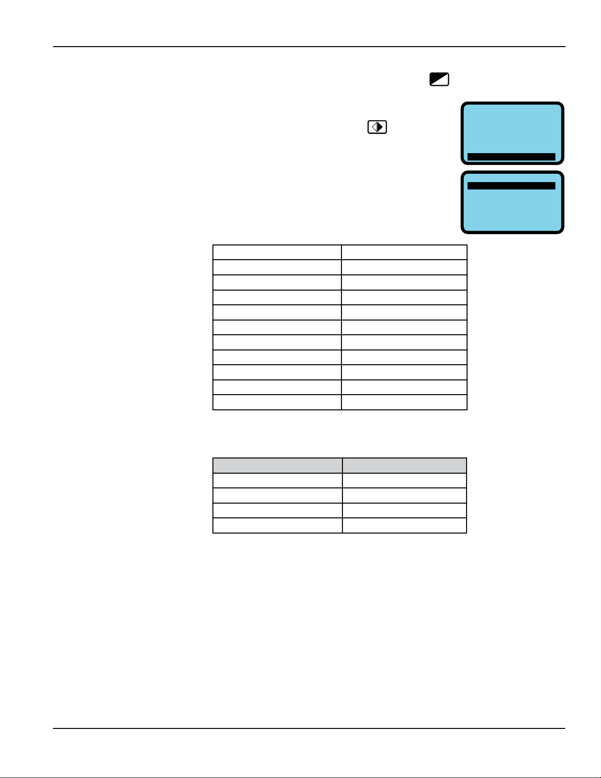
The menu can be accessed by briey pressing the
access code 4*******.
1. From Quick Start menu, push
repeatedly
until Main Menu is highlighted.
2. Enter into the main menu.
Sensor Body Model [S Model = XXX]
Liner Material [Lining = XXXXXX]
Unit Type [U type = XXXXXX]
Diameter [Diam. = in XXX]
KA [KA = ± XX.XXX]
KZ [KZ = ± XXXX]
Empty Pipe Detector [E.P.Detect = ON]
Empty Pipe Threshold [R max = kohm XXXX]
Elecrode Cleaning [El. Cleaning = MIN]
Sensor Cable Length [S.Cable = ft XXX]
Alarm Delay Interval [S.err.delay = XXX]
key and entering the
ENTER
ESC
QUICK START
E. P. Detect=
R max=kohm
Pls2=Gal
Tpls2=ms
A1S=Gal/m
Main Menu
MAIN MENU
1-Sensor
2-Units
3-Scales
4-Measure
5-Alarms
6-Inputs
ON
0220
1000.0
0500.0
004500
Sensor Body Model
[S.Model = XXX]
Enter the numeric code for the type of sensor body connected to the transmitter.
Body Type Sensor Code
Threaded Steel 011
Threaded Polypropylene 013
Wafer 002
Flanged 004
To change the setting, press enter to access the function. Use the right arrow key
to move the cursor and the up arrow key to change the code as per the table
above. Press enter to accept the change and exit the function. Press escape to
exit the program mode. Table of Contents
ONICON Incorporated 727.447.6140 Page 9 onicon.com
Page 10

FT-3100 TRANSMITTER PROGRAMMING GUIDE
Liner Material
[Lining = XXXXXX]
Unit Type
[U.type = XXXXXX]
Diameter
[Diam. = in XXX]
Select the sensor body liner material from the following list.
Liner Material* Code
PTFE PTFE
Polypropylene PP
Ebonite HR
*Disregard all liner material options that are not shown in this list.
To change the setting, press enter to access the function. Use the right arrow key
to move the cursor and the up arrow key to change the code as per the table
above. Press enter to accept the change and exit the function. Press escape to
exit the program mode. Table of Contents
This parameter congures the transmitter for U.S. (imperial) or SI (metric) units.
To change the existing setting, press enter to access the function and use the up
arrow key to change the setting. Press enter to accept the change and exit the
function. Press escape to exit the program mode. Table of Contents
This must be set to match the nominal diameter of the sensor body connected
to the transmitter. If the Unit Type is set to U.S. units, the nominal sizes will be in
inches. For SI units, the nominal sizes will be in millimeters.
KA
[KA = ± XX.XXX]
KZ
[KZ = ± XXXX]
To enter a new diameter, press enter to access the function. Use the right arrow
key to move the cursor and the up arrow key to change the value. Press enter to
accept changes and exit the function. Press escape to exit the program mode.
Table of Contents
KA is one of two coecients of calibration that are derived during the sensor
body factory calibration. Both variables must be programmed in to the
transmitter to ensure accurate ow measurement. The KA value is provided on
the certicate of calibration and on a label on the sensor body.
To enter a new coecient, press enter to access the function. Use the right arrow
key to move the cursor and the up arrow key to change the value. Press enter to
accept changes and exit the function. Press escape to exit the program mode.
Table of Contents
KZ is the second of two coecients of calibration that are derived during the
sensor body factory calibration. Both variables must be programmed in to the
transmitter to ensure accurate ow measurement. The KZ value is provided on
the certicate of calibration and on a label on the sensor body.
To enter a new coecient, press enter to access the function. Use the right arrow
key to move the cursor and the up arrow key to change the value. Press enter to
accept changes and exit the function. Press escape to exit the program mode.
Table of Contents
ONICON Incorporated 727.447.6140 Page 10 onicon.com
Page 11

FT-3100 TRANSMITTER PROGRAMMING GUIDE
Empty Pipe Detector
[E.P.Detect = ON]
Empty Pipe Threshold
[R max = kohm XXXX]
Electrode Cleaning
[El. Cleaning = MIN]
This setting enables or disables the empty pipe detector.
The Empty Pipe Detector senses when uid is drained from the pipe and the ow
sensing electrodes are exposed to air. When this occurs, the displayed ow rate
will drop to zero and the empty pipe icon will be displayed in the upper left-hand
side of the display window. If the current (mA) output alarm is active the milliamp
output will also indicate an alarm condition.
To change the existing setting, press enter to access the function and use the up
arrow key to turn the function on or off. Press enter to accept the change and
exit the function. Press escape to exit the program mode. Table of Contents
The empty pipe threshold function is used to set the maximum allowable
resistance value between the ow sensing electrodes in the transmitter. The
transmitter will go into empty pipe alarm when the value is exceeded. The default
value is 500. The maximum allowable value is 9,999.
To enter a new value, press enter to access the function. Use the right arrow key
to move the cursor and the up arrow key to change the resistance. Press enter to
accept the change and exit the function. Press escape to exit the program mode.
Table of Contents
When enabled, the electrode cleaning function transmits a depolarizing signal to
the electrodes in between ow measurement cycles. This function is enabled by
default whenever the empty pipe alarm is active. The default setting, when active,
is AVG. It should only be used with uid conductivities >100µS/cm.
Electrode Cleaning Settings Code
O OFF
Minimum MIN
Average AVG
Maximum MAX
To change the existing setting, press enter to access the function and use the up
arrow key to change the setting. Press enter to accept the change and exit the
function. Press escape to exit the program mode. Table of Contents
ONICON Incorporated 727.447.6140 Page 11 onicon.com
Page 12

FT-3100 TRANSMITTER PROGRAMMING GUIDE
Sensor Cable Length
[S.cable = ft XXX]
Enter the remote transmitter cable length. The allowable cable length is a
function of the uid conductivity with a maximum allowable cable length of 164ft
(50m). Use of the remote mount transmitter option with conductivity levels of
less the 15µS/cm is not recommended. Use the table below to determine the
maximum cable length for your installation.
Alarm Delay Interval
[S.err.delay = m XXX]
To enter a new value, press enter to access the function. Use the right arrow key
to move the cursor and the up arrow key to change the length. Press enter to
accept the change and exit the function. Press escape to exit the program mode.
Table of Contents
This function delays the activation of empty pipe, excitation error and signal error
alarms. The range of the delay interval is from 0 to 500 measurement cycles. For
meters up to 10” (250mm) in diameter this equates to 0 to 10 seconds. For 12” to
20” (300 to 500mm) meters, the interval range is from 0 to 25 seconds.
To enter a new value, press enter to access the function. Use the right arrow key
to move the cursor and the up arrow key to change the interval. Press enter to
accept the change and exit the function. Press escape to exit the program mode.
Table of Contents
ONICON Incorporated 727.447.6140 Page 12 onicon.com
Page 13

FT-3100 TRANSMITTER PROGRAMMING GUIDE
3.2 MENU 2 - UNITS
Diameter Unit Type [Diam = in]
Remote Mount Cable Unit Type [S.cable = ft]
Flow Rate Unit Type [FR unit = IMPERIAL]
Pulse 1 Unit Type [Pl1 unit = IMPERIAL]
Pulse 2 Unit Type [Pl2 unit = IMPERIAL]
Total Forward Flow Totalizer Unit Type [T+unit = IMPERIAL]
Total Forward Flow Totalizer Units [T+unit = Gal]
Total Forward Flow Totalizer Decimal Point Position [T+D.P. = X]
Partial Forward Flow Totaliazer Unit Type [P+unit = IMPERIAL]
Partial Forward Flow Totalizer Units [P+unit = Gal]
Partial Forward Flow Totalizer Decimal Point Position [P+D.P. = X]
Total Reverse Flow Totalizer Unit Type [T-unit = IMPERIAL]
Total Reverse Flow Totalizer Units [T-unit = Gal]
Total Reverse Flow Totalizer Decimal Point Position [T-D.P. = X]
Partial Reverse Flow Totalizer Unit Type [P-unit = IMPERIAL]
Partial Reverse Flow Totalizer Units [P-unit = Gal]
Partial Reverse Flow Totalizer Decimal Point Position [P-D.P. = X]
Temperature Unit Type [Temp.unit = °F]
Mass Units Enable [Mass units = OFF]
Specic Gravity Coecient [Sg = kg/dm
3
X.XXXX]
Diameter Unit Type
[Diam. = in]
Remote Mount Cable Unit Type
[S.cable = ft]
Flow Rate Unit Type
[FR unit = IMPERIAL]
This function sets the nominal diameter of the sensor body for U.S. (imperial) or
SI (metric) units. This setting changes the list of nominal diameters in SENSOR
menu (menu 1) [Diam. = ft XXX] from U.S to SI units.
To change the existing setting, press enter to access the function. Use the right
arrow key to change the selection. Press enter to accept the change and exit the
function. Press escape to exit the program mode. Table of Contents
This function sets the cable length measurement units for U.S. (imperial) or SI
(metric). This setting changes the way cable lengths are entered in SENSOR menu
(menu 1) [S.cable = ft XXX].
To change the existing setting, press enter to access the function. Use the right
arrow key to change the selection. Press enter to accept the change and exit the
function. Press escape to exit the program mode. Table of Contents
This function sets the list of ow measurement units for U.S (imperial) or SI
(metric).
To change the existing setting, press enter to access the function. Use the right
arrow key to change the selection. Press enter to accept the change and exit the
function. Press escape to exit the program mode. Table of Contents
ONICON Incorporated 727.447.6140 Page 13 onicon.com
Page 14

FT-3100 TRANSMITTER PROGRAMMING GUIDE
Pulse 1 Unit Type
[Pl1 unit = IMPERIAL]
Pulse 2 Unit Type
[Pl2 unit = IMPERIAL]
Total Forward Flow
Totalizer Unit Type
[T+ unit = IMPERIAL]
This function sets the list of totalizer measurement units for U.S. (imperial) or
SI (metric) for output 1. The function is only active when the output 1 function
selection [Out1 = XXXXXX] is set for scaled pulse
To change the existing setting, press enter to access the function. Use the right
arrow key to change the selection. Press enter to accept the change and exit the
function. Press escape to exit the program mode. Table of Contents
This function sets the list of totalizer measurement units for U.S. (imperial) or
SI (metric) for output 2. The function is only active when the output 2 function
selection [Out2 = XXXXXX] is set for scaled pulse
To change the existing setting, press enter to access the function. Use the right
arrow key to change the selection. Press enter to accept the change and exit the
function. Press escape to exit the program mode. Table of Contents
This function sets the list of forward ow totalizer measurement units for U.S
(imperial) or SI (metric).
To change the existing setting, press enter to access the function. Use the right
arrow key to change the selection. Press enter to accept the change and exit the
function. Press escape to exit the program mode. Table of Contents
Total Forward Flow
Totalizer Units
[T+ unit = Gal]
Total Forward Flow Totalizer
Decimal Point Position
[T+ D.P. = X]
Partial Forward Flow
Totalizer Unit Type
[P+ unit = IMPERIAL]
This function sets measurement unit for the forward ow totalizer.
To change the existing setting, press enter to access the function. Use the up
arrow key to change the selection. Press enter to accept the change and exit the
function. Press escape to exit the program mode. Table of Contents
This function sets the position of the decimal point when displaying the forward
ow total.
To move the decimal point, press enter to access the function. Use the up and/
or right arrow keys to change the selection. Press enter to accept the change and
exit the function. Press escape to exit the program mode. Table of Contents
This function sets the list of partial forward ow totalizer measurement units for
U.S (imperial) or SI (metric).
To change the existing setting, press enter to access the function. Use the right
arrow key to change the selection. Press enter to accept the change and exit the
function. Press escape to exit the program mode. Table of Contents
ONICON Incorporated 727.447.6140 Page 14 onicon.com
Page 15

FT-3100 TRANSMITTER PROGRAMMING GUIDE
Partial Forward Flow
Totalizer Units
[P+ unit = Gal]
Partial Forward Flow Totalizer
Decimal Point Position
[P+ D.P. = X]
Total Reverse Flow
Totalizer Unit Type
[T- unit = IMPERIAL]
Total Reverse Flow
Totalizer Units
[T- unit = Gal]
This function sets measurement unit for the partial forward ow totalizer.
To change the existing setting, press enter to access the function. Use the up
arrow key to change the selection. Press enter to accept the change and exit the
function. Press escape to exit the program mode. Table of Contents
This function sets the position of the decimal point when displaying the forward
ow total.
To move the decimal point, press enter to access the function. Use the up and/
or right arrow keys to change the selection. Press enter to accept the change and
exit the function. Press escape to exit the program mode. Table of Contents
This function sets the list of reverse ow totalizer measurement units for U.S
(imperial) or SI (metric).
To change the existing setting, press enter to access the function. Use the right
arrow key to change the selection. Press enter to accept the change and exit the
function. Press escape to exit the program mode. Table of Contents
This function sets measurement unit for the reverse ow totalizer.
To change the existing setting, press enter to access the function. Use the up
arrow key to change the selection. Press enter to accept the change and exit the
function. Press escape to exit the program mode. Table of Contents
Total Reverse Flow Totalizer
Decimal Point Position
[T- D.P. = X]
Partial Reverse Flow
Totalizer Unit Type
[P- unit = IMPERIAL]
Partial Reverse Flow
Totalizer Units
[P- unit = Gal]
This function sets the position of the decimal point when displaying the reverse
ow total.
To move the decimal point, press enter to access the function. Use the up and/
or right arrow keys to change the selection. Press enter to accept the change and
exit the function. Press escape to exit the program mode. Table of Contents
This function sets the list of partial reverse ow totalizer measurement units for
U.S (imperial) or SI (metric).
To change the existing setting, press enter to access the function. Use the right
arrow key to change the selection. Press enter to accept the change and exit the
function. Press escape to exit the program mode. Table of Contents
This function sets measurement unit for the partial reverse ow totalizer.
To change the existing setting, press enter to access the function. Use the up
arrow key to change the selection. Press enter to accept the change and exit the
function. Press escape to exit the program mode. Table of Contents
ONICON Incorporated 727.447.6140 Page 15 onicon.com
Page 16

FT-3100 TRANSMITTER PROGRAMMING GUIDE
Partial Reverse Flow Totalizer
Decimal Point Position
[P- D.P. = X]
Temperature Unit Type
[Temp. unit = °F]
Mass Units Enable
[Mass units = OFF]
Specic Gravity Coecient
[Sg = kg/dm3 X.XXXX]
This function sets the position of the decimal point when displaying the reverse
ow total.
To move the decimal point, press enter to access the function. Use the up and/
or right arrow keys to change the selection. Press enter to accept the change and
exit the function. Press escape to exit the program mode. Table of Contents
This function sets the measurement units for the on-board temperature sensor.
To change the existing setting, press enter to access the function. Use the right
arrow key to change the selection. Press enter to accept the change and exit the
function. Press escape to exit the program mode. Table of Contents
Enables or disables the mass measurement function. When enabled,
measurement unit lists for ow rates and totals will be in mass units.
To change the existing setting, press enter to access the function and use the up
arrow key to turn the function on or off. Press enter to accept the change and
exit the function. Press escape to exit the program mode. Table of Contents
This function is only enabled when mass units are enabled. The static value
entered here will be used to convert volumetric ow into mass ow.
To enter a new value, press enter to access the function. Use the right arrow key
to move the cursor and the up arrow key to change the coecient. Press enter to
accept the change and exit the function. Press escape to exit the program mode.
Table of Contents
ONICON Incorporated 727.447.6140 Page 16 onicon.com
Page 17

FT-3100 TRANSMITTER PROGRAMMING GUIDE
3.3 MENU 3 - SCALES
Full Scale Flow Rate 1
[FS1= Gal/m XXX.X]
Full Scale Flow Rate 1 [FS1 = Gal/m XXX.X]
Full Scale Flow Rate 2 [FS2 = Gal X.XX.X]
Pulse Output 1 Unit and Multiplier [Pls1 = X.XXXXX]
Pulse Output 1 Duration [Tpls1 = ms X.XXXXX]
Pulse Output 2 Unit and Multiplier [Pls2 = Gal X.XXXXX]
Pulse Output 2 Duration [Tpls2 = ms X.XXXXX
Frequency Output 1 Full Scale Frequency [Frq1 = Hz X.XXXXX]
Frequency Output 2 Full Scale Frequency [Frq2 = Hz X.XXXXX]
The full scale ow rate 1 function sets the unit of measure and time base for the
meter and the maximum ow rate for range 1. This eects the ow rate display
and the alarm function. It also sets the unit of measure and time base for the
analog output.
The maximum allowable ow rate is a function of the diameter of the ow sensor.
Regardless of the diameter, the maximum ow rate setting cannot exceed a
velocity of 10 m/s. The following rules apply to the maximum ow rate setting.
These may also aect the selection of the unit of measure and the time base.
• The largest numeric value representing ow is 9999. Larger values use units
with multipliers.
• The full scale ow rate setting cannot exceed 10 m/s
• The full scale ow rate must be greater than 0.4 m/s
US/IMPERIAL Volume Units
3
in
Cubic Inch
Gal US Gallon
ttG US Gallon x 10,000
3
ft
Cubic Foot
bbl Standard Barrel
BBL Barrel of Oil
3
hf
Kf
3
Cubic Foot x 100
Cubic Foot x 1,000
KGL US Gallon x 1,000
IGL Imperial Gallon
IKG Imperial Gallon x 1,000
Aft Acre Foot
MGL Mega Gallon (US)
IMG Imperial Mega Gallon
The list of units of measure available for selection can be in US/IMPERIAL or
SI units depending on the ow rate unit type [FR unit = IMPERIAL] selected in
UNITS menu (menu 2). In the same way, the list will show mass units, if mass units
are enabled [Mass units= OFF] in menu 2.
The tables below show the available units of measure.
Time Base
s Seconds
m Minutes
h Hours
US/IMPERIAL Mass Units
Oz Ounce
Lb Pound
Ton Short Ton (2,000 lbs)
d Days
SI/METRIC Volume Units
3
cm
Cubic Centimeter
ml Mililiter
l Liter
3
dm
Cubic Decimeter
dal Decaliter
hl Hectoliter
3
m
Cubic Meter
ML Megaliter
SI/METRIC Mass Units
g Gram
kg Kilogram
t Metric Ton (1,000 kg)
To enter a new value, press enter to
access the function. Use the right
arrow key to move the cursor and
the up arrow key to change the
entry. Press enter to accept the
change and exit the function. Press
escape to exit the program mode.
Table of Contents
ONICON Incorporated 727.447.6140 Page 17 onicon.com
Page 18

FT-3100 TRANSMITTER PROGRAMMING GUIDE
Full Scale Flow Rate 2
[FS2 = Gal/m XXX.X]
Scaled Pulse Output 1
[Pls1 = Gal X.XXXX]
The full scale ow rate 2 function sets the maximum ow rate for range 2, when
the autorange function [Autorange = ON/OFF] in MEASURE menu (menu 4) is
turned on. Range 2 uses the unit of measure and time base setting from full scale
ow rate 1.
The maximum allowable ow rate is a function of the diameter of the ow sensor.
Regardless of the diameter, the maximum ow rate setting cannot exceed a
velocity of 10 m/s. The following rules apply to the maximum ow rate setting.
These may also aect the selection of the unit of measure and the time base.
• The largest numeric value representing ow is 9999. Larger values use units
with multipliers.
• The full scale ow rate setting cannot exceed 10 m/s
• The full scale ow rate must be greater than 0.4 m/s
To enter a new value, press enter to access the function. Use the right arrow key
to move the cursor and the up arrow key to change the entry. Press enter to
accept the change and exit the function. Press escape to exit the program mode.
Table of Contents
This function is only available when output pulse 1 in OUTPUTS menu (menu 7)
[Out1 = XXXXX] is set to Pulses+, Pulses- or Pulses±. When active, scaled output
pulse 1 sets the unit of measure and the volume or mass that equates to one
pulse. This pulse weight setting is limited by the diameter of the ow sensor.
The list of units of measure available for selection can be in US/IMPERIAL or SI
units depending on the pulse 1 unit type [Pl1 unit = IMPERIAL] setting in UNITS
menu (menu 2). In the same way, the list will show mass units, if mass units are
enabled [Mass units= OFF] in menu 2. The tables below show the available units
of measure.
US/IMPERIAL Volume Units
3
in
Cubic Inch
Gal US Gallon
ttG US Gallon x 10,000
3
ft
Cubic Foot
bbl Standard Barrel
BBL Barrel of Oil
3
hf
Kf
3
Cubic Foot x 100
Cubic Foot x 1,000
KGL US Gallon x 1,000
IGL Imperial Gallon
IKG Imperial Gallon x 1,000
Aft Acre Foot
MGL Mega Gallon (US)
IMG Imperial Mega Gallon
SI/METRIC Volume Units
3
cm
Cubic Centimeter
ml Mililiter
l Liter
3
dm
Cubic Decimeter
dal Decaliter
hl Hectoliter
3
m
Cubic Meter
ML Megaliter
US/IMPERIAL Mass Units
Oz Ounce
Lb Pound
Ton Short Ton (2,000 lbs)
SI/METRIC Mass Units
g Gram
kg Kilogram
t Metric Ton (1,000 kg)
To enter a new value, press enter to access the function. Use the right
arrow key to move the cursor and the up arrow key to change the entry.
Press enter to accept the change and exit the function. Press escape to exit
the program mode. Table of Contents
ONICON Incorporated 727.447.6140 Page 18 onicon.com
Page 19

FT-3100 TRANSMITTER PROGRAMMING GUIDE
Output 1 Pulse Duration
[Tpls1 = ms X.XXXX]
Output 1 Full Scale Frequency
[Frq1 = Hz X.XXXXX]
Output 1 pulse duration is only active when scaled pulse output 1 [Pls1 = Gal
X.XXXX] is active. It is used to set the duration of each pulse. The duration is set
in milliseconds with a range of 0.4 to 9999.99.
Note: Pulse durations must match the requirements of the input they are connected
to. Very short pulse times may not be counted by the input and long duration
pulsed may damage electromechanical registers.
To enter a new value, press enter to access the function. Use the right arrow key
to move the cursor and the up arrow key to change the pulse length. Press enter
to accept the change and exit the function. Press escape to exit the program
mode. Table of Contents
This function is only available when output pulse 1 in OUTPUTS menu (menu 7)
[Out1 = XXXXX] is set to Freq+, Freq- or Freq±. When active, output 1 full scale
frequency sets maximum frequency for the output. This maximum frequency
equals the maximum ow rate set by full scale ow rate 1 [FS1 = Gal/m XXX.X] in
SCALES menu (menu 3).
To enter a new value, press enter to access the function. Use the right arrow key
to move the cursor and the up arrow key to change the pulse length. Press enter
to accept the change and exit the function. Press escape to exit the program
mode. Table of Contents
Scaled Pulse Output 2
[Pls2 = Gal X.XXXX]
This function is only available when output pulse 2 in OUTPUTS menu (menu 7)
[Out2 = XXXXX] is set to Pulses+, Pulses- or Pulses±. When active, scaled output
pulse 2 sets the unit of measure and the volume or mass that equates to one
pulse. This pulse weight setting is limited by the diameter of the ow sensor.
The list of units of measure available for selection can be in US/IMPERIAL or SI
units depending on the pulse 2 unit type [Pl2 unit= IMPERIAL] setting in UNITS
menu (menu 2). In the same way, the list will show mass units, if mass units are
enabled [Mass units = OFF] in menu 2. The tables below show the available units
of measure.
The tables shown for scaled pulse output 1 units of measure also apply to this
output.
To enter a new value, press enter to access the function. Use the right arrow key
to move the cursor and the up arrow key to change the entry. Press enter to
accept the change and exit the function. Press escape to exit the program mode.
Table of Contents
ONICON Incorporated 727.447.6140 Page 19 onicon.com
Page 20

FT-3100 TRANSMITTER PROGRAMMING GUIDE
Output 2 Pulse Duration
[Tpls2 = ms X.XXXX]
Output 2 Full Scale
Frequency
[Frq2 = Hz X.XXXXX]
Output 2 Pulse Duration is only active when scaled pulse output 2 [Pls2 = Gal
X.XXXX] is active. It is used to set the duration of each pulse. The duration is set
in milliseconds with a range of 0.4 to 9999.99.
Note: Pulse durations must match the requirements of the input they are connected
to. Very short pulse times may not be counted by the input and long duration
pulsed may damage electromechanical registers.
To enter a new value, press enter to access the function. Use the right arrow key
to move the cursor and the up arrow key to change the pulse length. Press enter
to accept the change and exit the function. Press escape to exit the program
mode. Table of Contents
This function is only available when output pulse 2 in OUTPUTS menu (menu 7)
[Out2 = XXXXX] is set to Freq+, Freq- or Freq±. When active, output 2 full scale
frequency sets maximum frequency for the output. This maximum frequency
equals the maximum ow rate set by full scale ow rate 2 [FS2 = Gal/m XXX.X] in
SCALES menu (menu 3).
To enter a new value, press enter to access the function. Use the right arrow key
to move the cursor and the up arrow key to change the pulse length. Press enter
to accept the change and exit the function. Press escape to exit the program
mode. Table of Contents
ONICON Incorporated 727.447.6140 Page 20 onicon.com
Page 21

FT-3100 TRANSMITTER PROGRAMMING GUIDE
FLOWRATE(%)
Example wtih damping to OFF
FILTERS
Damping = OFF
60
50
40
30
20
10
0
0 2 4 6 8 10 12 14 16 18 20 22
IN
>>>>>
.FLOWRATE
OUT
>>>>>
TIME (Sec)
.MEASURE
3.4 MENU 4 - MEASURE
Flow Signal Damping
[Damping = SMART]
Flow Signal Damping [Damping=SMART]
Low Flow Cut-o [Cut-o=%XXX]
Autorange [Autorange= OFF]
High Immunity Input Filter [H.im.inp = OFF]
The ow signal damping function allows the user to smooth out the eects of
sudden changes in the ow readings on the display and the output. Damping
may be applied using the “Smart” lter or by setting xed time interval ltering. It
is recommended to start with no damping.
Smart ltering automatically adapts to changing ow conditions. This lter will
provide signicant ltering when large, rapid changes are detected and minimal
ltering when ow is more stable. This type of ltering is useful when large
changes in ow occur at random intervals.
Time based ltering applies a xed time constant to the ltering algorithm.
Longer time constants increase the damping eect, but they also reduce
response time. See examples below. This type of ltering is useful when the
variations in ow are relatively constant and repeatable. Damping time interval
are 0.2, 0.5, 1, 2, 5, 10, 20, 50, 100, 200, 500 & 1000 seconds.
60
Example wtih damping to OFF
50
40
30
FLOWRATE(%)
20
10
0
0 2 4 6 8 10 12 14 16 18 20 22
.FLOWRATE
>>>>>
Damping = OFF
FILTERS
IN
TIME (Sec)
OUT
>>>>>
60
Example wtih damping to 5,0sec.
50
40
30
FLOWRATE(%)
20
.MEASURE
IN
10
0
0 2 4 6 8 10 12 14 16 18 20 22
.FLOWRATE
>>>>>
FILTERS
Damping = from 0.2s to 1000s
TIME (Sec)
OUT
>>>>>
.MEASURE
To enter a new value, press enter to access the function. Use the right arrow key
to move the cursor and the up arrow key to change the lter setting. Press enter
to accept the change and exit the function. Press escape to exit the program
mode. Table of Contents
ONICON Incorporated 727.447.6140 Page 21 onicon.com
Page 22

FT-3100 TRANSMITTER PROGRAMMING GUIDE
Low Flow Cut-o
[Cut-o = % XXX]
Autorange
[Autorange = OFF]
This function sets the low ow cut-o for ow measurement. The meter will
report all ow measurements below the threshold as zero ow. This cuto function is necessary to prevent small random noise signals from being
reported as ow. It is based on a percentage of the full scale ow rate 1 [FS1=
Gal/m XXX.X] in SCALES menu (menu 3). The allowable settings are between
0 and 25% of full scale. For most applications a value between 0.1 and 1.0% is
recommended.
To enter a new value, press enter to access the function. Use the right arrow
key to move the cursor and the up arrow key to change the cut-o percentage.
Press enter to accept the change and exit the function. Press escape to exit the
program mode. Table of Contents
When autorange is enabled the meter will operate with two dierent ow ranges.
In order to get the best results, range 1 [FS1= Gal/m XXX.X] in SCALES menu
(menu 3) must be larger than range 2 [FS2= Gal/m XXX.X].
When the ow rate increases and reaches the 100% of the full scale 1, then the
meter automatically switches to full scale 2. When the ow rate decreases to a
value on full scale 2 equal to the 90% of full scale.1, then the meter reverts to full
scale 1.
When autorange is enabled, the manual range change function [Range change=
OFF] in INPUTS menu (menu 6) cannot be used.
High Immunity Input Filter
[H. im. inp. = OFF]
Note: This function does NOT increase the accuracy of the measurement; it only
increases the resolution of the 4-20 mA output when the meter is operating at very
low ow rates (e.g. The ow rate of a domestic water distribution with much higher
daytime ow versus nighttime ow).
To change the existing setting, press enter to access the function and use the up
arrow key to turn the function on or off. Press enter to accept the change and exit
the function. Press escape to exit the program mode. T
able of Contents
When enabled, the high immunity input lter will increase ltering at the input
circuitry. This ltering is only eective when conductivity levels are greater than
500 µS/cm. It should only be used after all other methods of minimizing noise
have been employed as this will aect the ow measurement. The default setting
is o.
Note: The use of this lter will reduce ow measurement accuracy.
To change the existing setting, press enter to access the function. Use the up
arrow key to turn the function on or off. Press enter to accept the change and exit
the function. Press escape to exit the program mode. Table of Contents
ONICON Incorporated 727.447.6140 Page 22 onicon.com
Page 23

FT-3100 TRANSMITTER PROGRAMMING GUIDE
3.5 MENU 5 - ALARMS
Maximum Forward Flow
Alarm Threshold
[Max+ = Gal/m OFF]
Maximum Forward Flow Alarm Threshold [Max + = Gal/m OFF]
Maximum Reverse Flow Alarm Threshold [Max - = Gal/m OFF]
Minimum Forward Flow Alarm Threshold [Min + = Gal/m OFF]
Minimum Reverse Flow Alarm Threshold [Min - = Gal/m OFF]
Hysteresis Threshold [Hysteresis = % XX]
Current Output Alarm State Value [mA v.alarm = % XXX]
Frequency Output Alarm State Value [Hz v.alarm = % XXX]
This function sets the alarm threshold for maximum forward ow. Flow rates
above this threshold will trigger the alarm. The threshold value is entered as a
ow rate in the engineering units shown. The minimum value must be ≥1% of
the full scale maximum ow rate of the meter (10m/s or 32.8ft/s velocity). Alarm
threshold values are entered in 1% increments of the full scale limit up to 100%.
Example: In a 6” pipe 32.8 ft/s is equal to 2853 GPM. 1% of this value would be
approximately 28.5GPM. Alarm threshold values would be entered in increments
of 28.5 GPM.
To enter a value, press enter to access the function. Use the up arrow and right
arrow keys change the threshold value. Press enter to accept the change and exit
the function. Press escape to exit the program mode. T
able of Contents
Maximum Reverse Flow
Alarm Threshold
[Max - = Gal/m OFF]
Minimum Forward Flow
Alarm Threshold
[Min + = Gal/m OFF]
This function sets the alarm threshold for maximum reverse ow. Flow rates
above this threshold will trigger the alarm. The threshold value is entered as a
ow rate in the engineering units shown. The minimum value must be ≥1% of
the full scale maximum ow rate of the meter (10m/s or 32.8ft/s velocity). Alarm
threshold values are entered in 1% increments of the full scale limit up to 100%.
Example: In a 6” pipe 32.8 ft/s is equal to 2853 GPM. 1% of this value would be
approximately 28.5GPM. Alarm threshold values would be entered in increments
of 28.5 GPM.
To enter a value, press enter to access the function. Use the up arrow and right
arrow keys change the threshold value. Press enter to accept the change and exit
the function. Press escape to exit the program mode. Table of Contents
This function sets the alarm threshold for minimum forward ow. Flow rates
below this threshold will trigger the alarm. The threshold value is entered as a
ow rate in the engineering units shown. The minimum value must be ≥1% of
the full scale maximum ow rate of the meter (10m/s or 32.8ft/s velocity). Alarm
threshold values are entered in 1% increments of the full scale limit up to 100%.
Example: In a 6” pipe 32.8 ft/s is equal to 2853 GPM. 1% of this value would be
approximately 28.5GPM. Alarm threshold values would be entered in increments
of 28.5 GPM.
To enter a value, press enter to access the function. Use the up arrow and right
arrow keys change the threshold value. Press enter to accept the change and exit
the function. Press escape to exit the program mode. Table of Contents
ONICON Incorporated 727.447.6140 Page 23 onicon.com
Page 24

FT-3100 TRANSMITTER PROGRAMMING GUIDE
Minimum Reverse Flow
Alarm Threshold
[Min - = Gal/m OFF]
Alarm Hysteresis Threshold
[Hysteresis = % XXX]
This function sets the alarm threshold for minimum reverse ow. Flow rates
below this threshold will trigger the alarm. The threshold value is entered as a
ow rate in the engineering units shown. The minimum value must be ≥1% of
the full scale maximum ow rate of the meter (10m/s or 32.8ft/s velocity). Alarm
threshold values are entered in 1% increments of the full scale limit up to 100%.
Example: In a 6” pipe 32.8 ft/s is equal to 2853 GPM. 1% of this value would be
approximately 28.5GPM. Alarm threshold values would be entered in increments
of 28.5 GPM.
To enter a value, press enter to access the function. Use the up arrow and right
arrow keys change the threshold value. Press enter to accept the change and exit
the function. Press escape to exit the program mode. T
able of Contents
This function is used to dene the ow value where the meter exits the minimum
or maximum ow alarm state. When ows drop below the threshold for the
maximum ow alarm or rises above the minimum ow alarm by more than
the hysteresis percentage value, the meter exits the alarm state. It is set as a
percentage of the full scale ow rate 1 [FS1 = Gal/m XXX.X] in SCALES menu
(menu 3. The range of settings is 0-25% of full scale.
To enter a new value, press enter to access the function. Use the right arrow key
to move the cursor and the up arrow key to change the threshold percentage.
Press enter to accept the change and exit the function. Press escape to exit the
program mode. Table of Contents
mA Output Value When in
Alarm State
[mA v.alarm = % XXX]
This function establishes the 0/4-20mA output level when the meter is in an
alarm condition caused by an empty pipe, ADC error or an open coil indication.
The alarm value is set as a percentage of the 0/4 – 20mA output. The valid range
is 0-125% of 20mA. For example, a setting of 10% would cause the output to go
to 2mA when the meter is in the alarm state. One or more alarm icons will also be
displayed in the upper left hand side of the display when this alarm is active.
The default setting is 20% (4mA.
To enter a new value, press enter to access the function. Use the right arrow key
to move the cursor and the up arrow key to change the value. Press enter to
accept changes and exit the function. Press escape to exit the program mode.
Table of Contents
ONICON Incorporated 727.447.6140 Page 24 onicon.com
Page 25

FT-3100 TRANSMITTER PROGRAMMING GUIDE
Frequency Output Value When
in Alarm State
[Hz v.alarm = % XXX]
This function establishes the frequency output level for output 1 or output 2
when the meter is in an alarm condition caused by an empty pipe, ADC error or
an open coil indication.
This function is only available when either output pulse 1or output pulse 2 in
OUTPUTS menu (menu 7) [Out1 = XXXXX] [Out2 = XXXXX] is set to Freq+, Freqor Freq±.
The alarm value is set as a percentage of the full scale frequency. The valid range
is 0 – 125%. The default setting is 0%. One or more alarm icons will also be
displayed in the upper left hand side of the display when this alarm is active.
The default setting will cause the frequency output to indicate 0 Hz when in the
alarm state.
To enter a new value, press enter to access the function. Use the right arrow key
to move the cursor and the up arrow key to change the value. Press enter to
accept changes and exit the function. Press escape to exit the program mode.
Table of Contents
ONICON Incorporated 727.447.6140 Page 25 onicon.com
Page 26

FT-3100 TRANSMITTER PROGRAMMING GUIDE
3.6 MENU 6 - INPUTS
Total Forward Flow
Totalizer Reset Enable
[T+ reset = ON]
Partial Forward Flow
Totalizer Reset Enable
[P+ reset = OFF]
Total Forward Flow Totalizer Reset Enable [T+ reset = ON]
Partial Forward Flow Totalizer Reset Enable [P+ reset = OFF]
Total Reverse Flow Totalizer Reset Enable [T- reset = OFF]
Partial Reverse Flow Totalizer Reset Enable [P- reset = OFF]
Disable Flow Measurement via Pulse Input [Meas. lock = OFF]
Activate Autozero Calibration via Pulse Input [Calibration = OFF]
Change Flow Range via Pulse Input [Range change = OFF]
When enabled, this function allows the forward ow totalizer to be remotely
reset via the transmitter’s pulse input.
To change the existing setting, press enter to access the function and use the up
arrow key to turn the function on or off. Press enter to accept the change and
exit the function. Press escape to exit the program mode. Table of Contents
When enabled, this function allows the partial forward ow totalizer to be
remotely reset via the transmitter’s pulse input.
To change the existing setting, press enter to access the function and use the up
arrow key to turn the function on or off. Press enter to accept the change and
exit the function. Press escape to exit the program mode. Table of Contents
Total Reverse Flow Totalizer
Reset Enable
[T- reset = OFF]
Partial Reverse Flow Totalizer
Reset Enable
[P- reset = OFF]
Disable Totalizers via
Pulse Input
[Meas. Lock = OFF]
When enabled, this function allows the total reverse ow totalizer to be remotely
reset via the transmitter’s pulse input.
To change the existing setting, press enter to access the function and use the up
arrow key to turn the function on or off. Press enter to accept the change and
exit the function. Press escape to exit the program mode. Table of Contents
When enabled, this function allows the partial reverse ow totalizer to be
remotely reset via the transmitter’s pulse input.
To change the existing setting, press enter to access the function and use the up
arrow key to turn the function on or off. Press enter to accept the change and
exit the function. Press escape to exit the program mode. Table of Contents
When enabled, this function allows the all ow totalizers to be remotely disabled
via the transmitter’s pulse input.
To change the existing setting, press enter to access the function and use the up
arrow key to turn the function on or off. Press enter to accept the change and
exit the function. Press escape to exit the program mode. Table of Contents
ONICON Incorporated 727.447.6140 Page 26 onicon.com
Page 27

FT-3100 TRANSMITTER PROGRAMMING GUIDE
Activate Autozero Calibration
via Pulse Input
[Calibration = OFF]
Change Flow Range via
Pulse Input
[Range change = OFF]
When enabled, this function allows the autozero calibration function to be
remotely activated via the transmitter’s pulse input.
To change the existing setting, press enter to access the function and use the up
arrow key to turn the function on or off. Press enter to accept the change and
exit the function. Press escape to exit the program mode. Table of Contents
When enabled, this function allows the pulse input to be used to remotely
change the ow range to full scale ow rate 2 [FS2 = Gal/m XXX.X] in SCALES
menu (menu 3).
Note: this function cannot be used when the autorange [Autorange = OFF] function
in MEASURE menu (menu 4) is enabled.
To change the existing setting, press enter to access the function and use the up
arrow key to turn the function on or off. Press enter to accept the change and
exit the function. Press escape to exit the program mode. Table of Contents
ONICON Incorporated 727.447.6140 Page 27 onicon.com
Page 28

FT-3100 TRANSMITTER PROGRAMMING GUIDE
3.7 MENU 7 - OUTPUTS
Digital Output 1
Function Select
[Out1 = XXXXXX]
Digital Output 2
Function Select
[Out2 = XXXXXX]
OFF: Disables output
MAX AL+: Maximum forward ow rate alarm (Energized = no alarm)
MIN AL+: Minimum forward ow rate alarm (Energized = no alarm)
MAX/MIN+: Maximum or minimum forward ow rate alarms (Energized = no alarm)
MAX AL-: Maximum reverse ow rate alarm (Energized = no alarm)
MIN AL-: Minimum reverse ow rate alarm (Energized = no alarm)
MAX/MIN-: Maximum or minimum reverse ow rate alarms (Energized = no alarm)
MAX/MIN +/-: Maximum and minimum ow rate alarm, either direction (Energized = no alarm)
P. EMPTY: Empty pipe alarm output (Energized = no alarm)
HARDW.AL.: Master alarm for open coil, empty pipe or measurement error (Energized = no alarm)
OVERFLOW: Flow out of range alarm (Energized = no alarm)
ALL ALARMS: Activates when any alarm is active (Energized = no alarm)
EXT. COMM.: Allows the pulse output state (high or low) to be set via MODBUS
F.R. SIGN: Flow direction indication (Energized = reverse (-) ow)
*SCALE: Indicates which scale is active (Energized = Scale2)
FREQ+: Frequency output proportional to forward (+) direction ow rate
FREQ-: Frequency output proportional to reverse (-) direction ow rate
FREQ+/-: Frequency output to forward (+) / reverse (-) direction ow rate
PULSES.+: Scaled pulse output for forward (+) direction ow rate
PULSES-: Scaled pulse output for reverse (-) direction ow rate
PULSES+/-: Scaled pulse output for forward (+) / reverse (-) direction ow rate
Digital Output 1 Function Select [Out1 = XXXXXX]
Digital Output 2 Function Select [Out2 = XXXXXX]
mA Output 1 Function & Scaling [Out mA1 = 4_20 +/-]
Analog Output 1 Full Scale Value [A1S = Gal/m XXXXXX]
The available functions for digital output 1 are listed in the table below.
The available functions for digital output 2 are listed in the table below.
Digital Output Functions
*This function is only available when either the autorange [Autorange= OFF] function in menu 4 or the
change ow range via pulse input [Range change= OFF] function INPUTS (MENU 6 are active.
To change the setting, press enter to access the function. Use the up and right arrow keys to change
the setting. Press enter to accept the change and exit the function. Press escape to exit the program
mode. Table of Contents
ONICON Incorporated 727.447.6140 Page 28 onicon.com
Page 29

FT-3100 TRANSMITTER PROGRAMMING GUIDE
mA Output 1 Function &
Scaling
[Out mA1 = 4_20 +/-]
OUTPUT CURRENT IN mA FOR THE ASSOCIATED % OF FULL SCALE FLOW
mA Output Conguration Options Reverse Flow Value Zero Direct Flow Value
The available functions for current (mA) output 1 are listed in the table below.
There are three elds to modify when setting up an output:
• Zero scale value: 0 or 4mA
• Full scale value: 20 or 22mA
• Output function: + = forward (+) ow, - = reverse (-) ow, blank = absolute
ow, -0+ = zero ow center scale
The values corresponding to the scale points are shown in the following chart:
≥ -110% -100% 0% +100% ≥ +110%
0 - 20 + 0 0 0 20 20
0 - 22 + 0 0 0 20 22
4 - 20 + 4 4 4 20 20
4 - 22 + 4 4 4 20 22
0 - 20 - 20 20 0 0 0
0 - 22 - 22 20 0 0 0
4 - 20 - 20 20 4 4 4
4 - 22 - 22 20 4 4 4
0 - 20 20 20 0 20 20
0 - 22 22 20 0 20 22
4 - 20 20 20 4 20 20
4 - 22 22 20 4 20 22
0 - 20 - 0+ 0 0 10 20 20
0 - 22 - 0+ 0 1 11 21 22
4 - 20 - 0+ 4 4 12 20 20
4 - 22 - 0+ 4 4 12 20 22
To change the setting, press enter to access the function. Use the right arrow
key to move the cursor and the up arrow key to change the value. Press enter to
accept changes and exit the function. Press escape to exit the program mode.
Table of Contents
Analog Output 1 Full
This function sets the full scale ow value for the analog output.
Scale Value
[A1S = Gal/m XXXXXX]
The maximum allowable
ow rate is a function of the diameter of the ow sensor.
Regardless of the diameter, the maximum ow rate setting cannot exceed a
velocity of 10 m/s.
To change the setting, press enter to access the function. Use the right arrow
key to move the cursor and the up arrow key to change the value. Press enter to
accept changes and exit the function. Press escape to exit the program mode.
Table of Contents
ONICON Incorporated 727.447.6140 Page 29 onicon.com
Page 30

FT-3100 TRANSMITTER PROGRAMMING GUIDE
3.8 MENU 9 - DISPLAY
Display Language
[Language = GB]
Contrast Adjustment
[Contrast = X]
Display Language [Language = GB]
Contrast Adjustment [Contrast = X]
Display/User Interface Inactivity Time Interval [Disp. times = s XXX]
Display Refresh Frequency [D. rate = Hz X]
Enable Partial Totalizers [Part. tot. = OFF]
Enable Negative Totalizers [Neg. tot. = OFF]
Enable Net Totalizers [Net tot. = OFF]
Enable Quick Start Menu [Quick start = ON]
Default Display Page [Disp. fn. = X]
Default Lock [Disp. lock = OFF]
Select English (GB) or Italian (IT) for display text.
To change the existing setting, press enter to access the function. Use the up
arrow key to change the setting. Press enter to accept the change and exit the
function. Press escape to exit the program mode. Table of Contents
Set the desired contrast level to optimize viewing. The allowable range is 0 to 9.
To change the existing setting, press enter to access the function. Use the up
arrow key to change the setting. Press enter to accept the change and exit the
function. Press escape to exit the program mode. Table of Contents
Display/User Interface
Inactivity Time Interval
[Disp. times = s XXX]
Display Refresh Frequency
[D. rate = Hz X]
This function sets the time interval for returning to normal operation following
a period of inactivity when using the display/user interface. Allowable settings
range from 20 to 255 seconds.
To change the setting, press enter to access the function. Use the right arrow
key to move the cursor and the up arrow key to change the value. Press enter to
accept changes and exit the function. Press escape to exit the program mode.
Table of Contents
This function sets the display refresh rate. It is used to optimize viewing. It does
not aect the data refresh rate. The settings are 1, 2, 5 or 10 Hz.
To change the existing setting, press enter to access the function. Use the up
arrow key to change the setting. Press enter to accept the change and exit the
function. Press escape to exit the program mode. Table of Contents
ONICON Incorporated 727.447.6140 Page 30 onicon.com
Page 31

FT-3100 TRANSMITTER PROGRAMMING GUIDE
2 ALARM(S)
0.000GalP+
0
2 ALARM(S)
0
0.000
Gal/m
GalT+
0.000GalP+
0.204GalT-
0.000GalP-
2 ALARM(S)
0
0.000
Gal/m
GalT+
0.000GalP+
0.204GalT-
0.000GalP-
0
Enable Partial Totalizers
[Part. tot. = OFF]
This function enables or disables the display of partial totalizer data. When
enabled, the following pages are visible on the display.
To change the existing setting, press enter to access the function and use the up
arrow key to turn the function on or off. Press enter to accept the change and
exit the function. Press escape to exit the program mode. Table of Contents
9
5
2
Gal/m
Gal
T+
Gal
P+
2 ALARM(S)
6
P-
Gal
2 ALARM(S)
0.000
0.000
0.000GalT+
0.000GalP+
0.204GalT-
0.000
Enable Negative Totalizers
[Neg. tot. = OFF]
This function enables or disables the display of negative totalizer data. When
enabled, the following pages are visible on the display.
10
0.204GalT-
2 ALARM(S)
3
Gal/m
Gal
T-
Gal
P-
2 ALARM(S)
To change the existing setting, press enter to access the function and use the up
arrow key to turn the function on or off. Press enter to accept the change and exit
the function. Press escape to exit the program mode. T
0.204
0.000
5
11
2 ALARM(S)
0.000GalP-
6
P-
Gal
2 ALARM(S)
able of Contents
0.000GalT+
0.000GalP+
0.204GalT-
0.000
ONICON Incorporated 727.447.6140 Page 31 onicon.com
Page 32

FT-3100 TRANSMITTER PROGRAMMING GUIDE
2 ALARM(S)
0
+0.000
-0.204
Gal/m
Gal
Gal
TN
PN
Enable Net Totalizers
[Net tot. = OFF]
Enable Quick Start Menu
[Quick start = ON]
This function enables or disables the display of net totalizer data.
Note: This function is only available when negative totalizers are enabled [Neg.
tot.= ON] in DISPLAY menu (menu 9). When enabled, the following page is visible
on the display.
4
To change the existing setting, press enter to access the function and use the up
arrow key to turn the function on or off. Press enter to accept the change and
exit the function. Press escape to exit the program mode. Table of Contents
This function enables or disables the display of the quick start menu page.
To change the existing setting, press enter to access the function and use the up
arrow key to turn the function on or off. Press enter to accept the change and
exit the function. Press escape to exit the program mode. Table of Contents
ONICON Incorporated 727.447.6140 Page 32 onicon.com
Page 33

FT-3100 TRANSMITTER PROGRAMMING GUIDE
2 ALARM(S)
0
+0.00
Gal/m
0
0
2 ALARM(S)
0
+0.000
-0.204
Gal/m
Gal
Gal
TN
PN
2 ALARM(S)
0
0.000
Gal/m
GalT+
0.000GalP+
0.204GalT-
0.000GalP-
3 ALARM(S)
EXCITATION ERROR
PIPE EMPTY
2 ALARM(S)
0.000GalP+
2 ALARM(S)
0.127
E1 V
0.168E2 V
>10000.0E1 R kΩ
>10000.0E2 R kΩ
0
Gal/m
ft/s +0.000
100
75
50
25
0
Default Display Page
[Disp. fn = X]
1*
5
9
This function sets the default display page. This page will be displayed rst when
the transmitter exits the programming mode or when power is cycled. There are
13 possible display pages. They are numbered 0 -12. The display pages, with their
corresponding numbers, are shown below. Not all pages may be enabled on your
meter.
2
Gal/m
Gal
T+
Gal
P+
2 ALARM(S)
6
P-
Gal
2 ALARM(S)
10
0.000
0.000
0.000GalT+
0.000GalP+
0.204GalT-
0.000
3
Gal/m
Gal
T-
Gal
P-
2 ALARM(S)
7*
11
4
0.204
0.000
8*
0.000GalT+
2 ALARM(S)
12*
0*
*Factory default settings pages
Default Lock
[Disp. lock = OFF]
0.204GalT-
2 ALARM(S)
To change the existing setting, press enter to access the function. Use the up
arrow key to change the setting. Press enter to accept the change and exit the
function. Press escape to exit the program mode. Table of Contents
This function locks the default display page. When enabled, only the default
page is visible on the display.
To change the existing setting, press enter to access the function and use the up
arrow key to turn the function on or off. Press enter to accept the change and
exit the function. Press escape to exit the program mode. Table of Contents
2 ALARM(S)
0.000GalP-
ONICON Incorporated 727.447.6140 Page 33 onicon.com
Page 34

FT-3100 TRANSMITTER PROGRAMMING GUIDE
3.9 MENU 11 - FUNCTIONS
Reset Total Forward (+) Totalizer
[T+ reset]
Reset Partial Forward (+)
Totalizer
[P+ reset]
Reset Total Forward (+) Totalizer [T+ reset]
Reset Partial Forward (+) Totalizer [P+ reset]
Reset Total Reverse (-) Totalizer [T- reset]
Reset Partial Reverse (-) Totalizer [P- reset]
Load Factory Default Sensor Body Settings [Load Sens.f.def]
Load Factory Default Transmitter Settings [Load Conv.f.def]
To reset the following totals or reload factory defaults, press enter to access
the function and use the escape (ESC) key to confirm. Press enter to accept the
change and exit the function. Press escape to exit the program mode. Table of
Contents
This function resets the total forward (+) totalizer.
This function resets the partial forward (+) totalizer.
Reset Total Reverse (-) Totalizer
[T - reset]
Reset Partial Reverse (-)
Totalizer
[P - reset]
Load Factory Default
Sensor Body Settings
[Load Sens.f.def]
Load Factory Default
Transmitter Settings
[Load Conv.f.def]
This function resets the total reverse (-) totalizer.
This function resets the partial reverse (-) totalizer.
This function loads the factory default operating parameters for the sensor body.
Note: Reloading these values will void the factory calibration.
This function loads the factory default operating parameters for the sensor body.
ONICON Incorporated 727.447.6140 Page 34 onicon.com
Page 35

FT-3100 TRANSMITTER PROGRAMMING GUIDE
3.10 MENU 12 - DIAGNOSTIC
Self Diagnostic Test
[Self test]
Test Display
[Display test]
Self Diagnostic Test [Self test]
Test Display [Display test]
Simulate Flow Rate [Flow sim. = OFF]
Firmware Information [Firmware info]
Serial Number [S/N = XXXXXX]
Working Time [WT = XXXX:XX:XX:XX]
This function interrupts normal operation and performs a complete test cycle on
the measurement input circuits and on the coil excitation circuitry.
At the end of test the transmitter will revert to normal operation. This function is
automatically performed whenever power is cycled. This function also restarts the
transmitter.
Press enter to activate this function., Press escape when: “CONFIRM EXEC.?”
appears on the display to start the test. Press any other key to exit without
performing the test.
This function performs a pixel test on the display.
Press enter to perform the test.
Simulate Flow Rate
[Flow sim. = OFF]
Firmware Information
[Firmware info]
Serial Number
[S/N = XXXXXX]
This function activates an internal signal that simulates a ow rate. This allows
the outputs to be tested. The simulated ow rate is set as a percentage of the full
scale ow rate.
When enabled, the following ashing icon is displayed on the upper left side of
the display.
To enable simulation, press enter to access the function and use the up arrow key
to turn the function on. Press enter to accept the change and exit the function
The ow rate simulation percentage can be set by pressing the enter key from
any ow display page. Use the right arrow to move the cursor and the up arrow
key to change the value. Press enter to accept the ow rate percentage and
return to the display
Press the enter key followed by the escape key to end the simulation.
Displays a read only record of the current rmware and the date it was loaded.
Display a read only record of the electronics serial number
Working Time
Display of the accumulated operating time for the meter.
[WT = XXXX:XX:XX:XX]
ONICON Incorporated 727.447.6140 Page 35 onicon.com
Page 36

Flow and Energy Measurement
FT-3100 TRANSMITTER PROGRAMMING GUIDE
For questions regarding this manual, please contact the ONICON Technical Support
Department at 727-447-6140.
DOC-0000680
ONICON
ONICON Incorporated 11451 Belcher Road South, Largo, FL 33773 USA
727-447-6140 • www.onicon.com • sales@onicon.com
April 2019
 Loading...