

Page 1

FB-3500 BI-DIRECTIONAL ELECTROMAGNETIC FLOW METER
Installation and Operation Guide
11451 Belcher Road South, Largo, FL 33773 • USA • Tel +1 (727) 447-6140 • Fax (727) 442-5699
www.onicon.com • sales@onicon.com
05-140718-3 / 18611
Page 2

SAFETY INFORMATION
i
!
!
This meter was calibrated at the factory before shipment. To ensure correct use of the meter, please read
this manual thoroughly.
Regarding this Manual:
• This manual should be passed on to the end user.
• Before use, read this manual thoroughly to comprehend its contents.
• The contents of this manual may be changed without prior notice.
• All rights reserved. No part of this manual may be reproduced in any form without
ONICON’s written permission.
• ONICON makes no warranty of any kind with regard to this material, including, but not
limited to, implied warranties of merchantability and suitability for a particular purpose.
• All reasonable effort has been made to ensure the accuracy of the contents of this manual.
However, if any errors are found, please inform ONICON.
• ONICON assumes no responsibilities for this product except as stated in the warranty.
• If the customer or any third party is harmed by the use of this product, ONICON assumes
no responsibility for any such harm owing to any defects in the product which were not
predictable, or for any indirect damages.
Safety Precautions:
The following general safety precautions must be observed during all phases of installation,
operation, service, and repair of this product. Failure to comply with these precautions or with
specic WARNINGS given elsewhere in this manual violates safety standards of design,
manufacture, and intended use of the product. ONICON Incorporated assumes no liability for the
customer’s failure to comply with these requirements. If this product is used in a manner not
specied in this manual, the protection provided by this product may be impaired.
The following symbols are used in this manual:
WARNING
Messages identied as “Warning” contain information regarding the personal safety of
individuals involved in the installation, operation or service of this product.
CAUTION
Messages identied as “Caution” contain information regarding potential damage to the
product or other ancillary products.
IMPORTANT NOTE
Messages identied as “Important Note” contain information critical to the proper operation of
the product.
1 1451 Belcher Road South, Largo, FL 33773 • USA • Tel +1 (727) 447-6140 • Fax (727) 442-5699 • sales@onicon.com
FB-3500 Bi-Directional Insertion Electromagnetic Flow Meter Manual 05/14 - 0718-3 Page 2
Page 3

TABLE OF CONTENTS
1.0 INTRODUCTION .................................................................................................5
1.1 PURPOSE OF THIS GUIDE .......................................................................5
1.2 TYPICAL INSERTION ELECTROMAGNETIC FLOW METER ................5
1.3 STANDARD FEATURES AND SPECIFICATIONS ....................................6
1.4 ADDITIONAL REQUIRED HARDWARE ...................................................7
1.5 ADDITIONAL HARDWARE THAT MAY BE REQUIRED .........................8
1.5.1 Grounding Rings .......................................................................... 8
2.0 UNPACKING ...................................................................................................... 9
2.1 CHECKING THAT YOU HAVE RECEIVED EVERYTHING ......................9
3.0 INSTALLATION, REMOVAL & ADJUSTMENT ................................................10
3.1 INSTALLATION SITE SELECTION ........................................................10
3.1.1 General Site Selection Guidelines ............................................10
3.1.2 Insufcient Straight Run Site Selection Guidelines .................11
3.2 MECHANICAL INSTALLATION ............................................................. 12
3.2.1 Installation Kit ...........................................................................13
3.2.2 ONICON Standard Installation Hardware Kit ..........................13
3.2.3 ONICON Hot Tap Installation Hardware Kit ............................ 13
3.2.4 Customer Supplied Installation Hardware ............................... 14
3.2.5 Conrming the Stack Height .....................................................15
3.2.6 Installing the Flow Meter ..........................................................16
3.3 INSERTION OF THE METER ..................................................................17
3.3.1 Inserting the Flow Meter ...........................................................17
3.4 REMOVAL OF THE METER .................................................................... 18
3.5 WIRING CONNECTIONS ........................................................................20
3.5.1 Signal & Power Wiring Connections ......................................... 21
3.5.2 Earth Connections ......................................................................22
4.0 START-UP & COMMISSIONIING FOR ONICON INSERTION
ELECTROMAGNETIC FLOW METERS ............................................................. 23
4.1 HELPFUL HINTS FOR START-UP AND COMMISSIONING .................23
4.2 START-UP AND COMMISSIONING ....................................................... 24
4.3 START-UP AND COMMISSIONING WORKSHEET ............................... 25
4.4 TROUBLESHOOTING GUIDE ................................................................. 26
4.4.1 Earth Connections & Electrical Noise Reduction .....................26
APPENDIX
Conditions of Sale
1 1451 Belcher Road South, Largo, FL 33773 • USA • Tel +1 (727) 447-6140 • Fax (727) 442-5699 • sales@onicon.com
FB-3500 Bi-Directional Insertion Electromagnetic Flow Meter Manual 05/14 - 0718-3 Page 3
Page 4

1 1451 Belcher Road South, Largo, FL 33773 • USA • Tel +1 (727) 447-6140 • Fax (727) 442-5699 • sales@onicon.com
FB-3500 Bi-Directional Insertion Electromagnetic Flow Meter Manual 05/14 - 0718-3 Page 4
Page 5
!
SECTION 1.0: INTRODUCTION
We, at ONICON Incorporated, would like to thank you for purchasing our quality American made
FB-3500 Bi-Directional Electromagnetic Flow Meter. As our valued customer, our commitment to you
is to provide fast reliable service, while continuing to offer you quality products to meet your growing
ow measurement needs.
1.1 PURPOSE OF THIS GUIDE
We have written this guide to provide the persons responsible for the installation, operation and
maintenance of your ow meter with the most specic equipment information they will need.
This is NOT an electrical or plumbing trade manual.
WARNING
Please do not permit persons to install, operate or maintain this equipment unless they have a
complete knowledge of their trade skills and are competent to work on high pressure hot and cold
water and steam systems, according to their individual trades. Death or permanent injury may
result from accidents with these systems.
This guide is the basic reference tool for all ONICON FB-3500 Bi-Directional Electromagnetic
Flow Meters. If you have not purchased all of the options, there will be references in this manual
which are not applicable to your meter(s).
1.2 TYPICAL INSERTION ELECTROMAGNETIC FLOW METER
Faraday’s Law of electromagnetic induction states that a voltage will be induced in a conductor
when it passes through a magnetic eld, and the induced voltage will be directly proportional to
the velocity of the conductor.
ONICON FB-3500 Bi-Directional Electromagnetic Flow Meters generate pulsating magnetic elds
that are used to induce a voltage into the conductive uid owing through the pipe. Electrodes
located on the ow meter sensor head measure the induced voltage. Circuitry within the ow
meter electronics enclosure then converts the voltage to digital and analog signals that convey
ow rate and total data via connecting the cable to any of ONICON’s display devices, Btu meters
and/or to a data acquisition system.
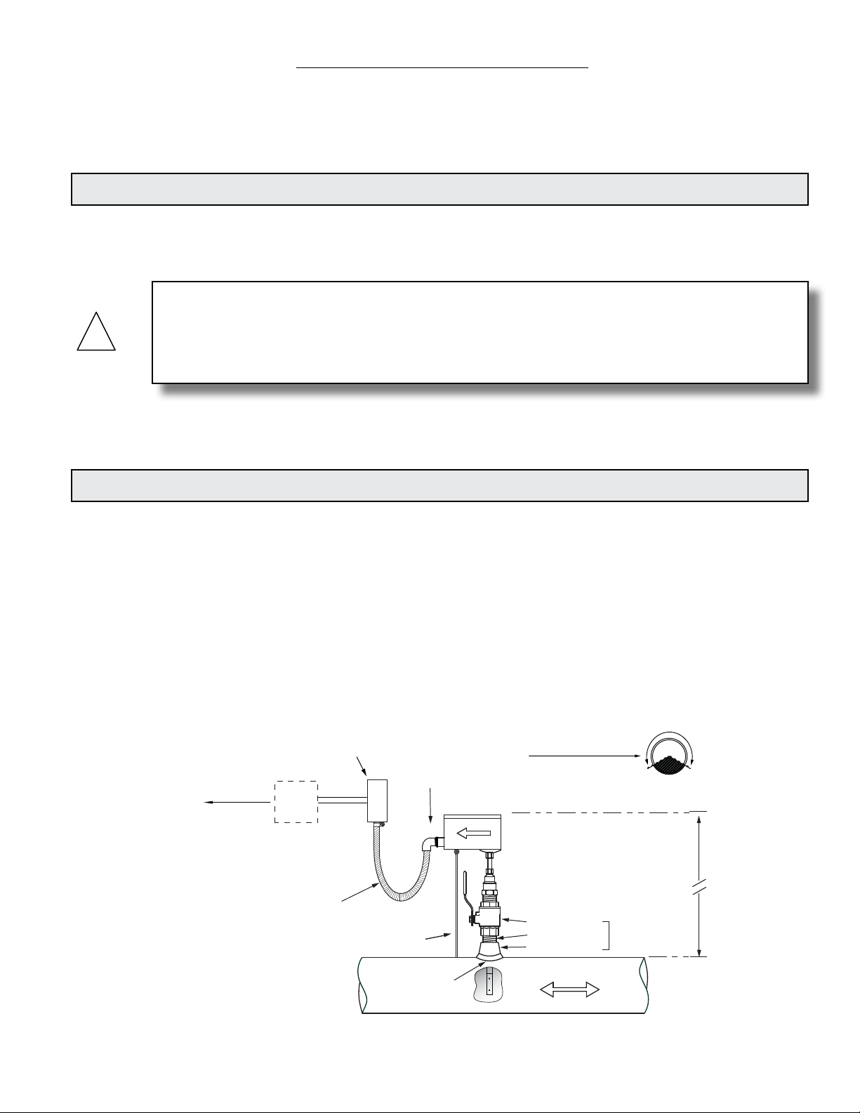
Typical Meter Installation
(New construction or scheduled shutdown)
Output signal(s)
to control
system
ONICON
Display or
BTU Meter
(Optional)
Allow enough slack
in the flexible conduit
to permit the meter
to be removed
from the valve.
Customer provided
conduit and adapters
Insertion depth
gage provided
with each meter
½" FNPT
conduit connection
• Install in vertical or horizontal pipe
• For horizontal pipe position meter
anywhere in upper 240˚
Standard Installation
Kit for Steel Pipe
1" Full port ball valve
1" Close nipple
1" Branch outlet
CLEARANCE
REQUIRED
FOR INSTALLATION
Typically
30" - 40"
depending on
pipe size and
height of valve
assembly.
1¼" for
hot tap
Minimum Hole Size = 1"
Must be centered
Note: Installation kits vary based on pipe material and application. For installations in pressurized (live)
systems, use "Hot tap" 1¼ inch installation kit and drill hole using a 1 inch wet tap drill.
FLOW
1 1451 Belcher Road South, Largo, FL 33773 • USA • Tel +1 (727) 447-6140 • Fax (727) 442-5699 • sales@onicon.com
FB-3500 Bi-Directional Insertion Electromagnetic Flow Meter Manual 05/14 - 0718-3 Page 5
Page 6

1.3 STANDARD FEATURES AND SPECIFICATIONS
Accuracy
± 1.0% of reading from 2 to 20 ft/sec
± 0.02 ft/sec below 2 ft/sec
Sensing Method
Electromagnetic, no moving parts
Pipe Size Range
3” through 72” nominal
Input Power
20 - 28 VAC 50/60 Hz, 250 mA maximum
20 - 28 VDC, 250 mA maximum
Liquid Temperature Range
15° to 250° F
Ambient Temperature Range
-5° to 150° F
Operating Pressure
400 PSI maximum
Pressure Drop
Less than 0.1 psi at 12 ft/s velocity in 3” and larger pipes
Materials of Construction
Wetted metal components - 316L stainless steel
Sensor head - Polypropylene
Electronics enclosure - Powder coat painted cast aluminum
Enclosure Rating
Weathertight, NEMA 4
Electrical Connections
10’ of PVC jacketed cable with ½” NPT conduit connection
OUTPUT SIGNALS PROVIDED
Analog Output (Isolated)
Selectable: 4-20 mA, 0-10 V or 0-5 V
Frequency Output
0 – 15 VDC, 0 – 500 Hz
Pulse/Contact Closure Outputs (four)
Isolated solid state dry contact
Contact maximum ratings: 100 mA, 50 VDC
Scalable Pulse Outputs (two)
Forward & Reverse Flow Totalization
Pulse Duration: 0.5, 1, 2 or 6 seconds
Directional Contact Output:
Switch closed when ow is in direction of ow arrow on enclosure
Latches at 0.2 ft/s
Switches within 20 seconds of direction change
Master Alarm Output:
Switch closed indicates alarm condition
This product is covered by one or more of the following patents: 6,431,011 and 6,463,807.
1 1451 Belcher Road South, Largo, FL 33773 • USA • Tel +1 (727) 447-6140 • Fax (727) 442-5699 • sales@onicon.com
FB-3500 Bi-Directional Insertion Electromagnetic Flow Meter Manual 05/14 - 0718-3 Page 6
Page 7
1.4 ADDITIONAL REQUIRED HARDWARE
All ONICON insertion type meters can be installed and removed via
a 1” or larger full port ball valve without system shutdown. The
terms “Standard” and “Hot Tap” refer to the installation method of
the isolation valve kit only.
Standard Installation Hardware: For new construction or
scheduled shutdown, once kit is installed, the ow meter can
be installed or removed without system shutdown.
Hot Tap Installation Hardware: For applications which require the
access hole in the pipe to be drilled through the valve using a
wet tap drilling machine while the hydronic system is
pressurized and operating.
NOTE: Installation hardware materials vary greatly based on pipe material, pipe size and
standard vs. hot tap versions.
1 1451 Belcher Road South, Largo, FL 33773 • USA • Tel +1 (727) 447-6140 • Fax (727) 442-5699 • sales@onicon.com
FB-3500 Bi-Directional Insertion Electromagnetic Flow Meter Manual 05/14 - 0718-3 Page 7
Page 8
1.5 ADDITIONAL HARDWARE THAT MAY BE REQUIRED
5/8
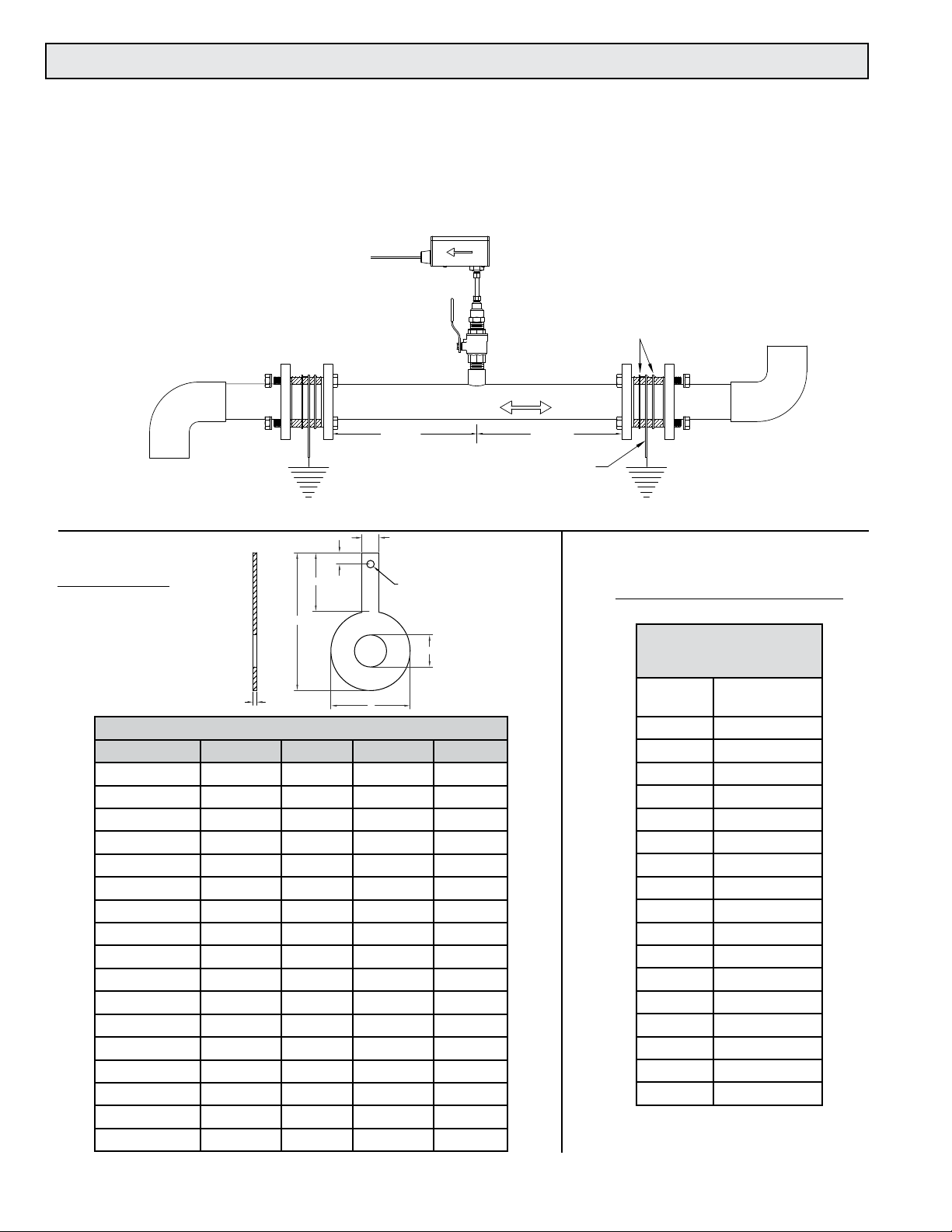
1.5.1 Grounding Rings
Grounding rings may be required whenever meters are installed in non-metallic or lined pipes.
Grounding rings placed before and after the meter eliminate electrical noise that will interfere
with the proper operation of the meter. ONICON provides grounding rings as an optional
accessory. Grounding ring dimensional information and part numbers are listed below. For proper
operation, grounding rings are required before and after the meter.
Typical Installation
Non-conductive Pipe
Gasket (4PL)
Flow Direction
DIMENSIONS
Nominal Size Bore A C D
1” 1 - 1/16 2 - 5/8 4 - 9/16 1 - 15/16
1.5” 1 – 9/16 3 – 3/8 5 - 5/16 1 - 15/16
2” 2 – 1/16 4 – 1/8 6 - 1/16 1 - 15/16
3” 3 – 1/16 5 – 3/8 7 - 5/16 1 - 15/16
4” 4 – 1/16 6 – 7/8 8 - 13/16 1 - 15/16
6” 6 8 – 3/4 10 - 11/16 1 - 15/16
8” 8 11 12 - 15/16 1 - 15/16
10” 9 – 1/2 13 – 3/8 15 - 5/8 2 - 1/4
12” 11 – 9/16 16 – 1/8 18 - 9/16 2 - 7/16
14” 13 – 1/2 17 – 3/4 20 - 3/8 2 - 5/8
16” 15 – 1/4 20 – 1/4 22 - 7/8 2 - 5/8
18” 17 – 3/8 21 – 5/8 24 - 1/4 2 - 5/8
20” 19 23 - 7/8 26 - 11/16 2 - 13/16
24” 23 28 – 1/4 31 - 1/8 2 - 7/8
30” 29 34 – 3/4 38 3 - 1/2
36” 35 41 – 1/4 45 - 1/4 4
42” 41 48 52 - 1/2 4 - 1/2
3/8
D
C
1/8”
A
Grounding Ring Dimensions
10 DIA
1/4
Bore
10 DIA
Grounding Ring (2PL)
ORDERING INFORMATION
ANSI Class 150
316 Stainless Steel
Grounding Rings (pair)
Nominal
Size
1” 19265
1½” 19266
2” 19267
3” 19268
4” 19269
6” 19270
8” 19271
10” 19272
12” 19273
14” 19274
16” 19275
18” 19276
20” 19277
24” 19278
30” 19279
36” 19280
42” 19281
ONICON Part
Number
1 1451 Belcher Road South, Largo, FL 33773 • USA • Tel +1 (727) 447-6140 • Fax (727) 442-5699 • sales@onicon.com
FB-3500 Bi-Directional Insertion Electromagnetic Flow Meter Manual 05/14 - 0718-3 Page 8
Page 9

SECTION 2.0: UNPACKING
ONICON insertion magnetic ow meters are packed and shipped in individual cartons. An optional
installation hardware kit INSTL 1 or INSTL 2, if ordered, will be packaged with each meter. All other
installation hardware and peripheral devices, including Btu meters and display modules, will be packaged
and shipped separately.
Please open all packages with care to prevent damage to their contents. Carefully inspect each item for
signs of damage in transit. The ow meter stem should be straight and free of blemishes or abrasions. The
sensor head should have a smooth continuous surface that is free of abrasions.
All ONICON products are shipped insured unless the customer specically requests otherwise. Please
notify the shipping company and ONICON immediately if any items are damaged in transit. Save all
packing material for inspection by the shipper.
2.1 CHECKING THAT YOU HAVE RECEIVED EVERYTHING
• Standard Documentation
Enclosed with each meter is a comprehensive documentation package that includes the
following items:
Installation and Operation Guide
Flow Meter Certicate of Calibration
Please notify the ONICON if any of these documents are missing.
FB-3500 Bi-Directional Insertion Electromagnetic Flow Meter
Optional INSTL1 or INSTL2 Installation Hardware Kit, if ordered
1 1451 Belcher Road South, Largo, FL 33773 • USA • Tel +1 (727) 447-6140 • Fax (727) 442-5699 • sales@onicon.com
FB-3500 Bi-Directional Insertion Electromagnetic Flow Meter Manual 05/14 - 0718-3 Page 9
Page 10

SECTION 3.0: INSTALLATION, REMOVAL AND ADJUSTMENT
!
WARNING
Insertion ow meters may be installed in pipes which are under high pressure. Accidents with
these systems can cause serious injury or death. Only persons experienced with high pressure
systems and related knowledge in the heating, cooling and uid metering elds should attempt
to install, adjust, or remove the ow meter. Please read all instructions before attempting to
insert or remove a ow meter.
ONICON will be happy to assist with technical recommendations and to provide guidance by
telephone or e-mail. On-site eld engineering, installation and service is also available at additional cost.
3.1 INSTALLATION SITE SELECTION
Install the ow meter where it will be accessible for personnel to perform necessary periodic
maintenance. The clearance required for installation is typically 30”- 40” from the pipe wall to
the nearest obstruction above the valve assembly. This clearance dimension will increase with
large diameter pipes. The environment should be free of corrosive liquids/fumes, temperature
extremes and heavy vibration. The following diagrams should be used as a guide to the proper
location for installing the meter.
3.1.1 General Site Selection Guidelines
GENERAL PRACTICES:
1. For best results, install the ow meter in a straight run of pipe, free of bends, tees,
valves, transitions and obstructions.
2. Straight run recommendations vary based on the nature of the upstream obstruction.
See the table below for guidelines in determining upstream straight run
recommendations based on the nature of the obstruction. Please note that depending
upon specic location details, more or less straight run may be required to produce a
satisfactory ow prole.
For 3” and larger pipe diameters
Obstruction on either side of meter
Single bend preceded by ≥ 9 diameters of
straight pipe
Pipe size reduction / expansion in straight
pipe run
Single bend preceded by ≤ 9 diameters of
straight pipe
Outowing tee / pump outow 20 Diameters
Multiple bends out of plane 30 Diameters
Inowing tee 30 Diameters
Control / modulating valve 30 Diameters
Straight run distance recommended
between meter and obstruction
10 Diameters
10 Diameters
15 Diameters
1 1451 Belcher Road South, Largo, FL 33773 • USA • Tel +1 (727) 447-6140 • Fax (727) 442-5699 • sales@onicon.com
FB-3500 Bi-Directional Insertion Electromagnetic Flow Meter Manual 05/14 - 0718-3 Page 10
Page 11

! i !
How To Determine The Available Straight Pipe Diameters:
For each application, locate the longest straight, unobstructed section of pipe (no bends, tees, valves,
other insertion probes, size transitions).
The longest straight pipe run in inches divided by nominal pipe size in inches equals
“diameters of straight pipe.”
For closed loop applications, consider both the supply and return lines as possible locations.
IMPORTANT NOTE
Always use the maximum available straight run. When more than the minimum required straight
run is available, place the meter such that the excess straight run is maximized on both sides of
the meter location.
• Acceptable to install in vertical pipe
• Position meter anywhere in upper 240°
for horizontal pipe
CLEARANCE
REQUIRED FOR
INSTALLATION
50%
Upstream
Downstream
3.1.2 Insufcient Straight Run Site Selection Guidelines
If there is insufcient available straight run, allow 50% of the run upstream and 50%
of the run downstream. If the total length of straight run is less than 20 diameters,
performance may degrade and consideration should be given to changing to the F-3100 or
F-3200 In-Line Electromagnetic Flow Meters.
Typically 30” - 40”
depending on pipe size
and height of valve
assembly.
50%
Some installations may work better with straight run optimized for ow in one direction.
For example, with ow meters installed in the bypass line between de-coupled constant
volume primary and variable secondary loops, it may be more important to accurately
measure positive ow (from supply to return.) Negative ow measurements (from return
to supply) are generally less critical, and it may be enough just to know that any negative
ow is present. In this scenario, maximizing straight run for positive ow might be a
preferred strategy.
1 1451 Belcher Road South, Largo, FL 33773 • USA • Tel +1 (727) 447-6140 • Fax (727) 442-5699 • sales@onicon.com
FB-3500 Bi-Directional Insertion Electromagnetic Flow Meter Manual 05/14 - 0718-3 Page 11
Page 12

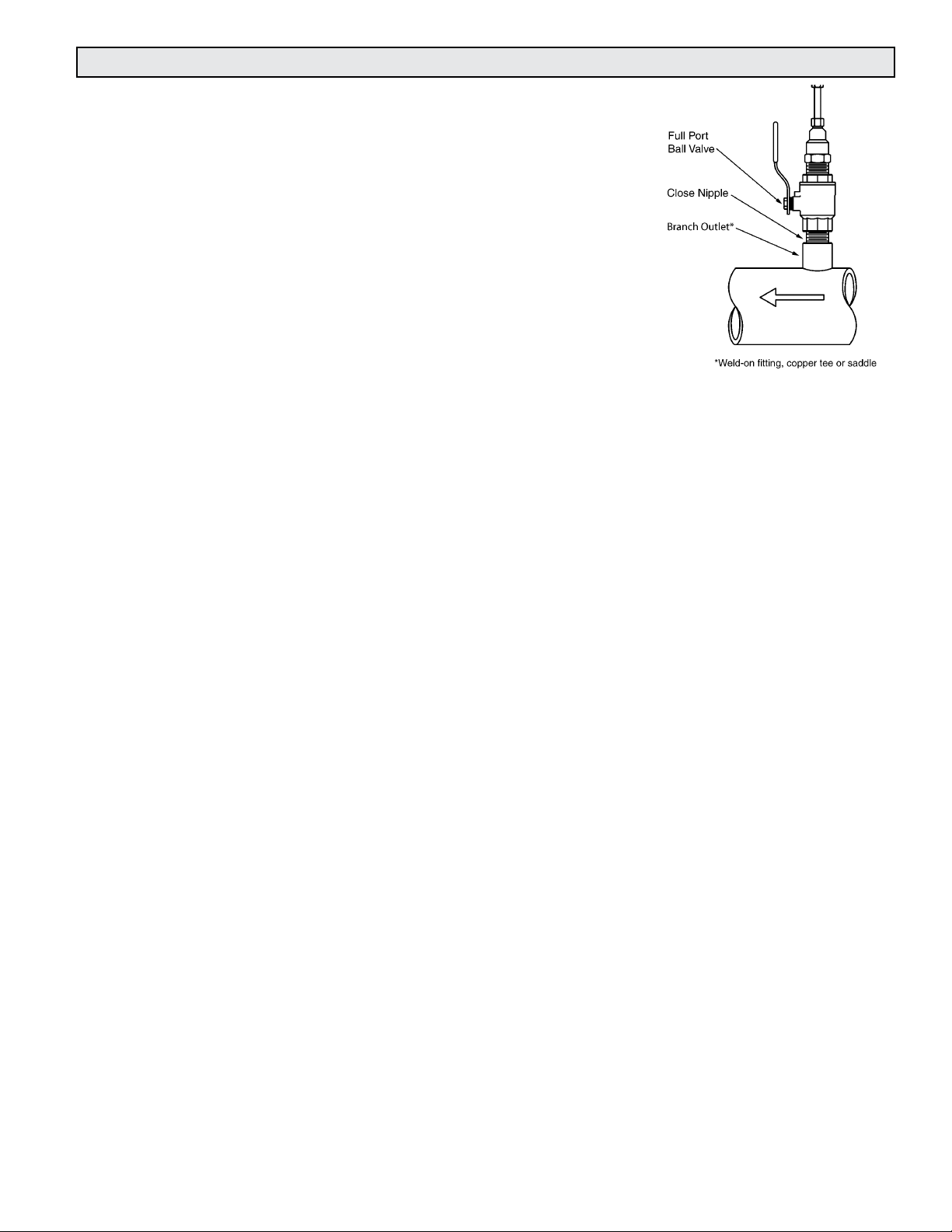
3.2 MECHANICAL INSTALLATION
!
! i !
ONICON Insertion Electromagnetic Flow Meters employ a hot tap adapter design that allows for
insertion and removal, when necessary, without interrupting ow and draining the pipe. To take
advantage of this feature, the ow meter must be installed through an isolation valve. The
installation must allow for sufcient overhead clearance to fully extract the meter, and a full 1”
opening in the pipe wall is required to clear the sensor head and allow for insertion. Make sure
that your valves and ttings are full port and at least 1” in actual internal diameter.
CLEARANCE
REQUIRED
FOR INSTALLATION
Typically
30" - 40"
depending on
pipe size and
height of valve
assembly.
Standard Installation
Kit for Steel Pipe
Minimum Hole Size = 1"
Must be centered
1" Full port ball valve
1" Close nipple
1" Branch outlet
NOTE: Use stainless steel or brass
close nipple only.
1¼" for
hot tap
CAUTION
ONICON insertion style ow meters must be installed through a valve assembly. Failure to do so
negates the ability to remove the meter without shutting down and draining the system. It will
also result in an excessive amount of stem protruding from the pipe. Excessive stem lengths
unneccessarily expose the meter to incidental damage.
IMPORTANT NOTE
1 1451 Belcher Road South, Largo, FL 33773 • USA • Tel +1 (727) 447-6140 • Fax (727) 442-5699 • sales@onicon.com
FB-3500 Bi-Directional Insertion Electromagnetic Flow Meter Manual 05/14 - 0718-3 Page 12
Flow meters installed through oversized access holes will be subjected to undesirable turbulence
that may affect the accuracy of the meter.
Page 13

3.2.1 Installation Kit
ONICON offers a wide range of installation hardware kits for commonly used pipe
materials. The kits are specically designed for ONICON ow meters, and their use is
recommended.
The use of ONICON installation hardware kits accomplishes two important objectives.
First, it ensures that the proper hardware is used. Second, it simplies order processing
by standardizing the dimensions of the installation hardware. ONICON must have an
accurate measurement of the overall height of the installation hardware as measured from
the outside wall of the pipe to the top of the valve in order to determine the correct stem
length when assembling the meter in our factory. ONICON documents refer to this
dimension as the stack height.
ONICON installation hardware kits consist of three separate component parts:
Some type of
threaded branch
outlet,
interconnecting
An
close nipple,
Different pipe materials require different branch outlets and may include additional
bushings to properly size the opening.
3.2.2 ONICON Standard Installation Hardware Kit
And a full port
isolation valve.
Standard installation hardware kits are designed to be installed on piping systems that
are drained and at atmospheric pressure. The access hole is drilled (1” minimum) prior
to installation of the branch outlet with 1” NPT threads, close nipple and full port ball
valve. Once the isolation valve is installed, the piping system can be ushed, lled and
pressurized. The ow meter may now be inserted or removed by hand without having to
drain the system. Please read all instructions before proceeding with meter insertion.
3.2.3 ONICON Hot Tap Installation Hardware Kit
ONICON offers an alternative installation hardware kit when it is not practical to relieve
pressure and drain the system. In this case, a 1¼” branch outlet, close nipple and 1¼” full
port ball valve are installed rst. Then, a hot tap drilling apparatus is used to drill a 1”
diameter hole through the valve. This eliminates the need to shut down and drain the
pipe. Please read all instructions before proceeding with meter insertion.
1 1451 Belcher Road South, Largo, FL 33773 • USA • Tel +1 (727) 447-6140 • Fax (727) 442-5699 • sales@onicon.com
FB-3500 Bi-Directional Insertion Electromagnetic Flow Meter Manual 05/14 - 0718-3 Page 13
Page 14

!
3.2.4 Customer Supplied Installation Hardware
!
!
There are occasions where circumstances require that the customer provide the
installation hardware or that the ow meter be installed through existing hardware. In
these cases, it is important to conrm that the installation hardware is suitable for use
with the ow meter provided by ONICON before it is installed. The installation must
allow for sufcient overhead clearance to fully extract the meter and a full 1” opening in
the pipe wall is required to clear the sensor head and allow for insertion. Make sure that
your valves and ttings are full port and at least 1” in actual internal diameter.
Installation hardware generally consists of three separate component parts:
Some type of
threaded branch
outlet,
An
interconnecting
close nipple,
And a full port
isolation valve.
CAUTION
Do not use threaded steel or slip PVC tees to provide the 1” opening in the pipe. Tees of this
type will cause signicant errors in the ow measurement.
CAUTION
In order to provide the ow meter with the correct stem length, ONICON must know the
overall height of the installation hardware as measured from the outside wall of the pipe to
the top of the valve where the meter is installed.
CAUTION
Use stainless steel or brass nipple only.
1 1451 Belcher Road South, Largo, FL 33773 • USA • Tel +1 (727) 447-6140 • Fax (727) 442-5699 • sales@onicon.com
FB-3500 Bi-Directional Insertion Electromagnetic Flow Meter Manual 05/14 - 0718-3 Page 14
Page 15

3.2.5 Conrming the Stack Height
ONICON insertion ow meter stem lengths vary according to the pipe diameter and the
height of the installation hardware stack. ONICON records the stack height dimension
provided by the customer at the time of order entry, and the information is used to size the
stem. The dimension is shown on the laminated insertion depth gage tag attached to the
meter.
Prior to installing the meter, conrm that the stack height recorded on the tag is close
to the actual stack height. Flow meter stems are intentionally over sized to allow for
variations of at least 2” in the stack height. Contact ONICON prior to installation if there is
any question regarding stack height or stem length. This way ONICON can offer you credit
for your meter if you decide to exchange the meter for one with a different stem length.
Returns may be subject to a restocking fee.
1 1451 Belcher Road South, Largo, FL 33773 • USA • Tel +1 (727) 447-6140 • Fax (727) 442-5699 • sales@onicon.com
FB-3500 Bi-Directional Insertion Electromagnetic Flow Meter Manual 05/14 - 0718-3 Page 15
Page 16

!
3.2.6 Installing the Flow Meter
!
When you are ready to rell the system, make sure that all lines are lled with water before
inserting the meter into the ow stream. If the lines are not lled and this is a hot water
system, some water may ash to steam and exceed the high temperature limit for the sensor
head assembly. This ash over could also exceed the pressure ratings of the meter and the
assembly could fail allowing steam and hot water to escape causing serious injury.
Tools needed for standard installation:
• 1 5/16” wrench or adjustable wrench
• 5/8” wrench or small adjustable wrench
• pipe wrench (to hold valve in place)
• pipe thread sealant
Flush, ll and pressure test the piping system prior to installing the meter. Loosen
clamping nut to facilitate installation.
WARNING
Clamping nut
Apply paste or
Teon tape as
necessary.
Keep sensor
head fully
withdrawn
during
installation.
Thread hot
tap adaper on
to ball valve
and tighten as
necessary.
Maintain a rm
grip on the
enclosure when
opening valve.
Crack
valve to
test for
leaks.
CAUTION
If there are any leaks around the clamping nut or stem, DO NOT ATTEMPT TO STOP THE
LEAKAGE BY OVERTIGHTENING THE CLAMPING NUT. Damage to this nut or the clamping
ring under the nut may prevent the assembly from properly holding the meter in the pipe. The
clamping nut is not part of the sealing mechanism. Any leaks in this area indicate that the “O”
ring is not sealing properly and you must contact ONICON for assistance.
1 1451 Belcher Road South, Largo, FL 33773 • USA • Tel +1 (727) 447-6140 • Fax (727) 442-5699 • sales@onicon.com
FB-3500 Bi-Directional Insertion Electromagnetic Flow Meter Manual 05/14 - 0718-3 Page 16
Page 17

!
3.3 INSERTION OF THE METER
WARNING
SYSTEM MAY BE UNDER HIGH PRESSURE. When adjusting the meter position or removing
it, be sure to hold the electronics enclosure rmly by hand before SLOWLY loosening the
positioning clamping nut. Failure to do this will allow the pressure to suddenly and rapidly
force the meter from the pipe causing serious injury. The meter could also be damaged or break
apart causing a break in the water seal with the resultant loss of large amounts of water. The
hand effort required to hold the meter will be 0.11 times the pipe pressure.
Begin by calculating the effort that will be required to hold the meter. Establish adequate footing
for this task, taking extra caution when working from a ladder or platform. Use the following
formula:
E=0.11 x P Where: E = effort in pounds
P = system pressure in pounds per square inch
Example: In a 300 PSI system, 33 pounds of effort is required to insert the meter into the pipe.
3.3.1 Inserting the Flow Meter
Step 1:
Maintain a rm grip
on the enclosure
to counteract
the effects of the
pressure in the pipe.
Step 2:
Slowly open the
valve to the full
open position.
Step 4:
Orient the enclosure to parallel with the pipe and
in alignment with the ow direction arrow.
Step 6:
Carefully tighten
the clamping
nut. DO NOT
OVERTIGHTEN.
Step 5:
Slowly push down on
the ow meter until
the bottom of the
enclosure rests on the
top of the depth gage.
Step 3:
Use the end of the depth gage to pierce any
insulation that may be present and rest the
gage on the outside wall of the pipe.
1 1451 Belcher Road South, Largo, FL 33773 • USA • Tel +1 (727) 447-6140 • Fax (727) 442-5699 • sales@onicon.com
FB-3500 Bi-Directional Insertion Electromagnetic Flow Meter Manual 05/14 - 0718-3 Page 17
Page 18

!
3.4 REMOVAL OF THE METER
SYSTEM MAY BE UNDER HIGH PRESSURE. When removing the ow meter, be sure to hold
the electronics enclosure rmly by hand before slowly loosening the positioning clamping
nut. Failure to do this will allow the pressure in the pipe to suddenly and rapidly force the
meter from the pipe causing serious injury. The meter could also be damaged or break apart
causing a break in the water seal with the resultant loss of large amounts of water. The hand
effort required to hold the meter will be 0.11 times the pipe pressure.
WARNING
Step 1:
Slowly loosen the position
clamping nut while
maintaining a rm grip on the
enclosure to counteract the
effect of pressure in the pipe.
1 1451 Belcher Road South, Largo, FL 33773 • USA • Tel +1 (727) 447-6140 • Fax (727) 442-5699 • sales@onicon.com
FB-3500 Bi-Directional Insertion Electromagnetic Flow Meter Manual 05/14 - 0718-3 Page 18
Step 2:
Carefully withdraw the
ow meter stem from
the pipe until the sensor
head is fully inside the
hot tap adapter.
Page 19

!
!
NOTE:
The hot tap adapter will contain
a small amount of water.
Step 3:
After the meter is completely
withdrawn, slowly close the
valve to isolate ow.
Step 4:
After the valve is completely closed,
unscrew the hot tap adapter from the
valve. For hot water meters, partially
unscrew the adapter to vent pressure
before fully removing the meter.
CAUTION
The main cause of damage to meters comes from accidentally closing the valve on the sensor
head. To avoid this, gently rotate the meter by twisting the electronics enclosure back and forth
(twist the stem, do not bend it) while you slowly close the valve. If the valve touches any part of
the meter, you will feel it as you are twisting the meter. If the valve touches anything, it means
the meter is not fully withdrawn. Usually a gentle twisting motion while withdrawing the meter
will clear any obstruction and permit the meter to withdraw completely. (Excessive build-up on
the stem may require the hot tap “O” ring to be lubricated with silicone.)
WARNING
In hot water systems, even a small amount of water can cause serious personal injury. Use extra
caution when working with hot water meters.
1 1451 Belcher Road South, Largo, FL 33773 • USA • Tel +1 (727) 447-6140 • Fax (727) 442-5699 • sales@onicon.com
FB-3500 Bi-Directional Insertion Electromagnetic Flow Meter Manual 05/14 - 0718-3 Page 19
Page 20

3.5 WIRING CONNECTIONS
!
!
Make all connections to the attached 10ft cable.
The most common causes of electronic failures are miswired connections during installation.
When adding additional cable, record and carefully document any substitution of wire colors.
Additional cable may be purchased from ONICON that will allow you to maintain the existing
color coding.
All electrical connections to the FB-3500 must be made through the 10ft cable provided with the
meter. This cable is not designed to be removed in the eld, and any attempt to do so will
compromise the weather tight integrity of the enclosure.
The cable provided contains 22 AWG color-coded wires for signal and power and a separate
18 AWG green/yellow earth wire.
Special care is required to ensure that the FB-3500 is connected to earth through the green/yellow
earth wire. This connection is required to prevent random electrical noise from interfering with
the operation of the meter. (See section 3.5.2 for details.)
CAUTION
Do not attempt to remove the existing cable or to remove the factory installed connection tting.
Doing so will compromise the weather tight integrity of the enclosure and may void the warranty.
CAUTION
Only qualied personnel should attempt to make electrical connections to the FB-3500. Failure
to properly connect the FB-3500 power, signal or earth connections may result in damage to the
FB-3500 and/or to associated peripheral equipment.
1 1451 Belcher Road South, Largo, FL 33773 • USA • Tel +1 (727) 447-6140 • Fax (727) 442-5699 • sales@onicon.com
FB-3500 Bi-Directional Insertion Electromagnetic Flow Meter Manual 05/14 - 0718-3 Page 20
Page 21

!
3.5.1 Signal and Power Wiring Connections
Customer provided
conduit and adapters
Output signal(s)
to control
system
ONICON
Display or
BTU Meter
(Optional)
Allow enough slack
in the flexible conduit
to permit the meter
to be removed
from the valve.
Insertion depth
gage provided
with each meter
½" FNPT
conduit connection
FLOW
Wire Color Description Notes
Red (+) Supply voltage: 24±4 VDC @ 250 mA or 24±4 VAC,
60 Hz, 6 VAC
Black (-) Isolated supply voltage common Connect to power supply (-): DC (-) or
Green / Y ellow Earth ground connection Required to operate the meter
Green (+) Isolated frequency output Required when connecting to ONICON
Yellow (-) Frequency output common
Blue (+) Isolated analog output Congurable as a 4-20 mA, 0-10 V or
Brown (-) Isolated analog output common
Gray Forward ow, scaled output, isolated dry contact Scalable dry contact pulse output for
Violet
Gray / Black Reverse ow, scaled output, isolated dry contact Scalable dry contact pulse output for
Violet / Black
Orange / Black Flow direction indicator, isolated dry contact Contact closed when ow is in direction
White / Black
Diagnostic Signals
Orange Master alarm, isolated dry contact Dry contact closure signal indicating
White
Connect to power supply (+): DC (+) or
AC (line)
AC (neutral)
display or BTU meter
0-5 V output
forward ow totalization
reverse ow totalization
of arrow on meter
fault condition
CAUTION
Failure to provide a proper earth connection to the meter may result in excessive electrical
noise that will interfere with the operation of the meter.
1 1451 Belcher Road South, Largo, FL 33773 • USA • Tel +1 (727) 447-6140 • Fax (727) 442-5699 • sales@onicon.com
FB-3500 Bi-Directional Insertion Electromagnetic Flow Meter Manual 05/14 - 0718-3 Page 21
Page 22

! i ! ! i !
3.5.2 Earth Connection
FB-3500 Bi-Directional Electromagnetic Flow Meters are designed to detect microvolt
signal levels at the electrodes located on the sensor head. These signals are generated
as conductive uids ow through the magnetic eld generated by the meter. If enough
random electrical noise is present at the electrodes, it can interfere with the ow
measurement. Care must be taken during installation to minimize the effects of electrical
noise on the ow meter.
The most effective way to minimize the effects of electrical noise is to make sure that
the pipe, the uid and the ow meter body are all connected to earth ground. This
accomplishes two important goals. First, it ensures that the pipe, uid and ow meter are
all at the same electrical potential, and second, it ensures that this electrical potential is
the same as earth ground.
In order to be certain that the meter is properly connected to earth, the ow meter earth
cable should be run directly to a known earth connection. The length of this earth cable
should be as short as practically possible, preferably ≤25 feet in length. The table below
lists earth connections from best to worst. If necessary, a separate earth cable should be
connected to the metal pipe near the meter.
IMPORTANT NOTE
Non-metallic pipes are more susceptible to electrical noise. Grounding rings installed upstream
and downstream of the meter location to reduce the electrical noise present in the pipe may be
required for proper operation. Refer to section 1.5.1 of this manual for additional information on
the use of grounding rings.
Earth Connections (stranded wire 14 – 18 AWG)
Best Earth grounding rod driven into the ground
Earth wire connected directly to the building electrical service panel.
Worst Earth wire connection inside an electrical outlet near the meter.
IMPORTANT NOTE
Under certain circumstances, connecting the meter to earth through the green/yellow earth wire
may increase the amount of electrical noise present at the meter. Contact ONICON for technical
assistance if you experience increased noise levels with the earth wire connected to earth.
1 1451 Belcher Road South, Largo, FL 33773 • USA • Tel +1 (727) 447-6140 • Fax (727) 442-5699 • sales@onicon.com
FB-3500 Bi-Directional Insertion Electromagnetic Flow Meter Manual 05/14 - 0718-3 Page 22
Page 23

SECTION 4.0: START-UP & COMMISSIONING FOR ONICON
INSERTION ELECTROMAGNETIC FLOW METERS
4.1 HELPFUL HINTS FOR START-UP AND COMMISSIONING
A step-by-step procedure and companion worksheet are located on the next two pages. Please
read all installation instructions carefully before proceeding with installation, start-up and
commissioning.
1. ONICON ow meters are individually calibrated for a particular application. Be
sure to verify the pipe size and location.
2. The electronic ow sensing systems will not work in air.
3. When measuring analog output signals, remember that current (mA) must be
measured in series, while voltage is measured in parallel. If the 4-20 mA signal
is already connected to a control system, you must break the connection and
measure the signal in series.
4. When measuring frequency outputs in Hz, take your multimeter out of “autorange
mode” and manually set the range for a voltage level above 15 VDC. This will
prevent false readings when signal is not present.
5. All wiring connections should be made at the end of the factory cable. Do not
attempt to remove the factory installed cable or change the orientation of the
electronics enclosure.
6. Never connect power to analog or frequency output signal wires. ONICON FB-3500
ow meters are not “loop powered” devices.
1 1451 Belcher Road South, Largo, FL 33773 • USA • Tel +1 (727) 447-6140 • Fax (727) 442-5699 • sales@onicon.com
FB-3500 Bi-Directional Insertion Electromagnetic Flow Meter Manual 05/14 - 0718-3 Page 23
Page 24

4.2 START-UP AND COMMISSIONING
Please read the entire procedure before proceeding. A worksheet for checking off the following
steps and recording measured values is located on the next page.
1. Conrm ow meter
location. Conrm adequate
straight pipe run to achieve
desired results.
2. Conrm pipe size. Conrm that the meter is tagged for the pipe size in which it is installed. When in doubt,
3. Conrm insertion depth and
orientation.
4. Conrm control system
programming.
5. Conrm connection to
correct ONICON display or
Btu meter (if ordered).
6. Verify wiring before
connecting power.
7. Conrm correct supply voltage. Verify that 24 (±4) V is available.
8. Connect power. Wait approximately 45 seconds after power-on before proceeding further.
The following steps require ow in the pipe. Flow signal readings should be taken while holding the ow rate constant, if possible.
Otherwise, take the various output readings as quickly as possible.
9. Test ow direction indicator.
Conrm that ow direction
contact closure output
changes state when the ow
direction reverses.
10. Measure and record
frequency output.
Is the meter located in the correct location as required by the plans?
Compare actual straight pipe upstream and downstream of the meter location to
recommended distances identied in this manual. Contact ONICON’s technical support
department to discuss specics of your application. If straight pipe run is very short,
consult factory PRIOR to installing the meter to discuss possibility of upgrade to an
F-3000 series in-line meter.
measure the circumference of the pipe. Pipe O.D. = (circumference / 3.14) – (insulation
thickness x 2).
Each ow meter comes with an attached insertion gage and instruction tag. Ensure that
the meter is inserted to the correct depth and that the electronics enclosure is parallel to
the pipe with the arrow in the direction of ow.
Conrm that the control system input point is properly congured for the analog range
(or scale factor) identied on the calibration tag & certicate.
Conrm that the ow meter serial number matches the ONICON display or Btu meter
serial number (when ordered together).
Prior to connecting the power, verify that the wiring is correct as shown in this manual and/
or the additional wiring diagram provided with ONICON display or Btu meter. If in doubt,
contact ONICON for assistance before proceeding further.
Following the steps outlined in sections 3.3.1 of this manual, loosen the clamping nut, rotate
the enclosure 180° and conrm that the ow direction contact closure changes state.
Return the meter to its correct orientation in the pipe, reset the insertion depth and tighten
the clamping nut.
The frequency output signal is a 0-15 VDC pulsed output ranging up to 200 Hz and must
be measured with a multimeter. Measue DC frequency (Hz) from GREEN (+) to YELLOW
(-). Also measure DC volts on same wires. Five to seven is normal for a pulsating output.
Zero VDC indicates no output.
GPM = frequency in Hz X 60
meter factor in ppg (Refer to calibration tag for meter factor.)
11. Measure and record
analog or pulse outputs.
Current Output:
Voltage Output:
Scaled Output:
12. Compare various output
signals to each other and to
the ow rate displayed by the
control system.
End of standard start-up and commissioning. Please contact ONICON at (727) 447-6140 with any questions.
Refer to ow meter wiring diagram for wire colors for the various outputs available, based
on your
particular ow meter model. Use the following formulas to calculate ow rate from
measured analog signals:
GPM = (measured current in mA - 4) X Full Scale Analog Flow Rate
16
GPM = measured VDC X Full Scale Analog Flow Rate
10
Each contact closure = unit volume identied as “Scale Factor” (measure and record time
interval between contact closures)
Compare the ow rates calculated in steps 10 and 11 to each other and to the ow
rate indicated by the control system. Refer to troubleshooting guide when readings are
inconsistent.
1 1451 Belcher Road South, Largo, FL 33773 • USA • Tel +1 (727) 447-6140 • Fax (727) 442-5699 • sales@onicon.com
FB-3500 Bi-Directional Insertion Electromagnetic Flow Meter Manual 05/14 - 0718-3 Page 24
Page 25

4.3 START-UP AND COMMISSIONING WORKSHEET
Please read all installation instructions carefully prior to proceeding with these steps. Use the
following worksheet for checking off the commissioning steps and recording measured values.
Steps 9 - 12 require ow in the pipe. Flow signal readings should be taken while holding
the ow rate constant, if possible. Otherwise, take the various output readings as quickly as
possible.
STEP TEST/MEASUREMENT S/N: _________ S/N: ________ S/N: ________ S/N: _________
1. Meter location:
2.
3. Insertion depth
4. Control system
5. Match display or Btu
6. Signal connections
7. Supply voltage veried:
8. Connect power:
The following steps require ow in the pipe. Flow signal readings should be taken while holding the ow rate
constant if possible. Otherwise, take the various output readings as quickly as possible.
9. Flow direction indicator
10. Frequency output(s):
Conrm pipe size:
and orientation:
programming:
meter serial number
(S/N) if ordered:
veried:
changes state (Y/N)
Avg = green
Average frequency (Hz):
Average frequency
(VDC):
Calculated ow rate:
11. Analog or pulse
output(s)
4-20 mA signal:
0-5 / 0-10 V signal:
Scaled output interval:
Calculated ow rate:
12. Flow rate displayed
by control system:
___________Hz
_________VDC
_________GPM
___________mA
_________VDC
_____________
_________GPM
_________GPM _________GPM _________GPM _________GPM
___________Hz
_________VDC
_________GPM
___________mA
_________VDC
_____________
_________GPM
___________Hz
_________VDC
_________GPM
___________mA
_________VDC
_____________
_________GPM
___________Hz
_________VDC
_________GPM
__________mA
_________VDC
_____________
_________GPM
1 1451 Belcher Road South, Largo, FL 33773 • USA • Tel +1 (727) 447-6140 • Fax (727) 442-5699 • sales@onicon.com
FB-3500 Bi-Directional Insertion Electromagnetic Flow Meter Manual 05/14 - 0718-3 Page 25
Page 26

4.4 TROUBLESHOOTING GUIDE
NOTE: Also refer to the START-UP AND COMMISSIONING GUIDE located on page 22.
REPORTED PROBLEM POSSIBLE SOLUTIONS
No signal • Verify that the meter is properly inserted into the pipe.
• Verify that the electronics enclosure is parallel with the pipe.
• Verify 24 V supply voltage.
• Verify correct wiring to control system (see wiring diagram).
• Verify that there is ow in the pipe.
• Verify that the meter earth cable is connected to earth.
• Check to see if the alarm contact closure output is closed (orange &
white wires). A closed contact could indicate either an empty pipe or
excessive electrical noise, possibly due to a poor earth ground.
• Low conductivity water (≤ 20 µsiemens) may activate the empty pipe
detector and/or increase the potential for electrical noise problems.
Reading is too high or
low
• Verify pipe size. Contact ONICON if pipe size is different from
calibration tag.
• Verify that the meter is properly inserted into the pipe.
• Verify that the electronics enclosure is parallel with the pipe.
• Verify correct wiring to control system (see wiring diagram).
• Conrm that the output signals are consistent with each other
(frequency vs. analog, etc).
• Conrm that the control system is programmed for correct ow range or
scale factor.
• Verify that the meter earth cable is connected to earth. A poor earth
connection can lead to excessive noise that can affect the ow reading.
Flow direction
indicator does not
change state when ow
direction changes.
Analog signal seems
high or low and does
not correspond to
frequency output
• Meter will not switch at very low ow velocities. Conrm that ow
velocity exceeds 0.2 ft/sec.
• Check for open connections between each contact closure wire (orange /
black & white / black) and the control system input.
• Check for ground loop or offset voltage:
• Disconnect analog signal input from control system and measure analog
output directly from the ow meter. Reconnect signal input to control
system and measure the analog signals again. Any difference between
these readings indicates a potential ground loop or offset voltage. Please
contact ONICON for further assistance.
Control system displays
ow rate, but no ow
rate is indicated on the
local display module or
• Verify that all wires from the ow meter are connected to the display
module or Btu meter.
• The frequency output wires (green and yellow) must be connected for
any ONICON display or Btu meter.
Btu meter
4.4.1 Earth Connections & Electrical Noise Reduction
Introduction
FB-3500 Electromagnetic Flow Meters are designed to detect microvolt signal levels at the
electrodes located on the sensor head. These signals are generated as conductive uids
ow through the magnetic eld generated by the meter. If enough random electrical noise
is present at the electrodes, it can interfere with the ow signal measurement. Care must
be taken during installation to minimize the effects of electrical noise on the ow meter.
1 1451 Belcher Road South, Largo, FL 33773 • USA • Tel +1 (727) 447-6140 • Fax (727) 442-5699 • sales@onicon.com
FB-3500 Bi-Directional Insertion Electromagnetic Flow Meter Manual 05/14 - 0718-3 Page 26
Page 27

! i !
Minimizing Electrical Noise
The most effective way to minimize the effects of electrical noise is to make sure that
the pipe, the uid and the ow meter body are all connected to earth ground. This
accomplishes two important goals. First, it ensures that the pipe, uid and ow meter are
all at the same electrical potential. Second, it ensures that this electrical potential is
the same as earth ground.
IMPORTANT NOTE
Non-metallic pipes are more susceptible to electrical noise. Grounding rings installed upstream
and downstream of the meter location to reduce the electrical noise present in the pipe may be
required for proper operation. Refer to section 1.5.1 of this manual for additional information
on the use of grounding rings.
In order to be certain that the meter is properly connected to earth, the ow meter earth
cable should be run directly to a known earth connection. The length of this earth cable
should be as short as practically possible, preferably ≤25 feet in length. The table below
lists earth connections from best to worst. If necessary, a separate earth cable should be
connected to the metal pipe near the meter.
Earth Connections (stranded wire 14 - 18 AWG)
Best Earth grounding rod driven into the ground to the depth of the water table.
Earth wire connected directly to the building electrical service panel.
Worst Earth wire connection inside an electrical outlet near the meter.
Diagnosing Electrical Noise Problems
When diagnosing electrical noise problems, it is important to understand that one of four
possible conditions are likely to exist. They are as listed in the table below. In order to
minimize the effects of noise, it is helpful to understand which of the following conditions
are present.
Earth Connection at
Flow Meter
Good earth connection
≤ 25 feet from ow meter
Good earth connection
≤ 25 feet from ow
meter
Poor earth connection Pipe & uid are
Pipe / Fluid Earth
Connection
Pipe & uid are
connected to earth
Pipe & uid are not
connected to earth
connected to earth
Poor earth connection Pipe & uid are not
connected to earth
Expected
Noise
Level
Low None required
Moderate A separate earth connection can be
made directly to the metal pipe or to the
uid. Non-metalic pipes may require
grounding rings installed upstream and
downstream of the meter location.
Moderate Removing the earth connection at the
ow meter may reduce the noise level.
If this is a long wire run, break the
connection where the wire connects to
the cable coming out of the ow meter. If
noise level is still too high, locate a better
earth connection for the ow meter.
High Locate a better earth connection for
the ow meter. If noise level is still too
high, locate a better earth connection
for the pipe or uid.
Possible Remedies
1 1451 Belcher Road South, Largo, FL 33773 • USA • Tel +1 (727) 447-6140 • Fax (727) 442-5699 • sales@onicon.com
FB-3500 Bi-Directional Insertion Electromagnetic Flow Meter Manual 05/14 - 0718-3 Page 27
Page 28

1. ACCEPTANCE: The following Conditions of Sale apply to all sales of ONICON’s products. These provisions shall apply even
CONDITIONS OF SALE
if ONICON fails to object to provisions appearing on, incorporated by, referenced in, or attached to Buyer’s purchase order
form. Buyer’s acceptance of delivery of ONICON’s products constitutes its acceptance of these Conditions of Sale.
2. DELIVERY AND TITLE: All product shipments are Ex Works shipping point and title passes to the Buyer at the time ONICON
delivers the merchandise to the carrier. Risk of loss or damage to the product passes to the Buyer at the time ONICON delivers
the product to the carrier. The Buyer immediately upon receipt should inspect all shipments, and should there be any evidence of
damage or loss in transit, Buyer must le claims or tracers upon carrier. ONICON will assist in tracing shipments upon request.
3. LIMITED WARRANTY: ONICON warrants that for a period of two (2) years following the date of original shipment of an
ONICON product: (i) the product will conform to ONICON’s standard written specications applicable to such product in effect
on the date of Buyer’s order, or as modied by ONICON’s quotation or Buyer’s purchase order accepted by ONICON, (ii) the
product will be free from defects in workmanship, and (iii) that ONICON has title to the product prior to shipment to the Buyer;
provided, however, that the warranties provided herein shall be void and may not apply in the event Buyer misuses or
damages a product, including, but not limited to, any use by the Buyer of a product for an application other than one of a type
approved by ONICON. ONICON’s sole liability and Buyer’s sole remedy for any breach of the foregoing warranty is for
ONICON to repair or replace, at ONICON’s option, any defective product that is returned to ONICON during the warranty
period. EXCEPT AS MAY BE SPECIFICALLY AGREED BY ONICON IN WRITING IN RELATION TO EACH SALE, NO
OTHER WARRANTIES SHALL APPLY, WHETHER EXPRESSED, IMPLIED OR STATUTORY, AND THERE SHALL BE NO
IMPLIED WARRANTIES OF MERCHANTABILITY AND FITNESS FOR A PARTICULAR PURPOSE.
4. REMEDIES: ONICON’s OBLIGATION UNDER THE FOREGOING WARRANTIES IS LIMITED SOLELY TO REPAIR OR
REPLACEMENT, AT ONICON’s OPTION, OF DEFECTIVE OR NONCONFORMING PRODUCTS. ONICON SHALL NOT BE
LIABLE FOR CONSEQUENTIAL, INDIRECT, PUNITIVE, INCIDENTAL, OR SPECIAL DAMAGES WHETHER FOUND ON
CONTRACT, TORT OR ANY OTHER THEORY OF LAW. No products shall be returned to ONICON without its prior consent
and transportation and insurance costs shall be prepaid. Any repair or replacement of ONICON’s products under the foregoing
warranty will be at no charge to the Buyer provided such repair is done at the ONICON factory or authorized service center.
ONICON products that are repaired or replaced under this warranty will be returned to Buyer via the same method of shipment
use to return the product to ONICON. Repair or replacement of ONICON products is conditioned upon ONICON’s
acknowledgement of any alleged defect or nonconformance during the warranty period and issuance of a Return
Authorization number. All product returns must reference the Return Authorization number on the outside of the shipping
carton and on any paperwork referencing the return.
5. PRICES AND PAYMENT TERMS: The prices set forth in the most recent quote or acknowledgement as applicable, supersede
all previous prices or quotations. All quotations are subject to change or withdrawal without notice except as may be specically
noted on the face of the quotation. The prices shown do not include sales, excise or government charges payable by ONICON to
Federal, State, or local authority. Any such tax or charge now or hereafter imposed upon the sale or shipment of the products
under this contract will be added to the purchase price. Buyer agrees to reimburse ONICON for such tax or charge or provide
ONICON with an acceptable exemption certicate. Payment of invoices will be due 30 days from the date of shipment of the
products contained therein. In the event that payment of an invoice is not received by the invoice due date, ONICON will assess
a late fee not to exceed 1.5% per month or 18% per year, or the maximum allowableby law whichever is lower.
6. CANCELLATION: Buyer may cancel its order, or any part of it, by sending written notice of cancellation to ONICON and
paying a reasonable cancellation fee as determined by ONICON. The reasonable cancellation fee will reect, among other
factors, the expenses already incurred and commitments made by ONICON, sales and administrative costs and prot as
determined by ONICON. If Buyer received a reduced price based on the quantity of products ordered, but has not purchased
the applicable quantity at the time of cancellation, Buyer will pay the price it would have paid had ONICON’s sale price been
based on the quantity actually purchased.
7. CHANGES: If Buyer makes any changes in its drawings, designs, or specications applicable in any contract with ONICON
that cause an increase or decrease in the cost of performance of the contract, or if such changes result in rework or obsolescence, an
equitable adjustment shall be made to the contract. Such changes are subject to ONICON’s prior written consent.
8. EXCUSABLE DELAY: ONICON shall under no circumstance be responsible for failure to ll any order or orders when due to: res,
oods, riots, strikes, freight embargoes or transportation delays, shortage of labor, inability to secure fuel, material supplies, or power
at current price or on account of shortages thereof, acts of God or of the public enemy, any existing or future laws or acts of the
Federal or State Government (including specically, but not exclusively, and orders, rules or regulations issued by any ofcial or
agency of any such government) affecting the conduct of ONICON’s business with which ONICON in its judgment and discretion
deems it advisable to comply as a legal or patriotic duty, or due to any cause beyond ONICON’s reasonable control.
9. PATENTS: ONICON shall defend all suits or proceedings brought against Buyer or its customers arising from claimed
infringements of any patent, trademark, service mark or copyright for any product furnished by ONICON and shall indemnify it
against all costs, fees, and damages on the condition Buyer promptly noties ONICON in writing and provides information and
assistance to enable ONICON to conduct the defense, provided that ONICON shall have no such obligation in case of
infringement resulting from ONICON’s conformance to special requirements of Buyer. If ONICON is not able to settle any such
suit or proceeding on acceptable terms, ONICON may, at its option, require return of the infringing product and refund the
purchase price to Buyer less a reasonable allowance for depreciation or use.
10. FAIR LABOR STANDARDS ACT: ONICON represents that all products delivered under this contract are furnished in
accordance with the applicable provisions of the Fair Labor Standards Act as amended.
11. APPLICABLE LAW: This document and any resulting contract shall be governed by and construed in accordance with the
laws of the State of Florida. The courts of the State of Florida and the federal courts located in Florida shall have jurisdiction
and venue with respect to litigation to this contract. In the event of litigation, the prevailing party shall be entitled to recover
attorney’s fees and costs from the non-prevailing party, including appellate attorney’s fees.
12. MODIFICATIONS: These Conditions of Sale along with the prices, quantities, delivery schedules and other provisions and
instructions in applicable quotations by ONICON or Buyer’s purchase orders accepted by ONICON shall constitute the entire
agreement between ONICON and Buyer pertaining to any resulting contract. They can be modied only in writing.
1 1451 Belcher Road South, Largo, FL 33773 • USA • Tel +1 (727) 447-6140 • Fax (727) 442-5699 • sales@onicon.com
FB-3500 Bi-Directional Insertion Electromagnetic Flow Meter Manual 05/14 - 0718-3 Page 28
 Loading...