

Page 1
F-5100 Inline
Thermal Mass Flow Meter
Installation and Operation Guide
11451 Belcher Road South, Largo, FL 33773 • USA • Tel +1 (727) 447-6140 • Fax (727) 442-5699
0686-11 / 18332
www.onicon.com • sales@onicon.com
05-15
Page 2

SAFETY INFORMATION
!
!
i
This meter was calibrated at the factory before shipment. To ensure correct use of the meter, please
read this manual thoroughly.
Regarding This Manual:
• This manual should be passed on to the end user.
• Before use, read this manual thoroughly to comprehend its contents.
• The contents of this manual may be changed without prior notice.
• All rights reserved. No part of this manual may be reproduced in any form without
ONICON’s written permission.
• ONICON makes no warranty of any kind with regard to this material, including, but not
limited to, implied warranties of merchantability and suitability for a particular purpose.
• All reasonable efforts have been made to ensure the accuracy of the contents of this
manual. However, if any errors are found, please inform ONICON.
• ONICON assumes no responsibilities for this product except as stated in the warranty.
• If the customer or any third party is harmed by the use of this product, ONICON assumes
no responsibility for any such harm owing to any defects in the product which were not
predictable, or for any indirect damages.
Safety Precautions:
The following general safety precautions must be observed during all phases of installation,
operation, service, and repair of this product. Failure to comply with these precautions or
with specic WARNINGS given elsewhere in this manual violates safety standards of design,
manufacture, and intended use of the product. ONICON Incorporated assumes no liability for
the customer’s failure to comply with these requirements. If this product is used in a manner not
specied in this manual, the protection provided by this product may be impaired.
The following symbols are used in this manual:
WARNING
Messages identied as WARNING contain information regarding the personal safety of individuals
involved in the installation, operation or service of this product.
CAUTION
Messages identied as CAUTION contain information regarding the potential damage to the product
or other ancillary products.
IMPORTANT NOTICE
Messages identied as IMPORTANT NOTICE contain information critical to the proper operation of
the product.
11451 Belcher Road South, Largo, FL 33773 • USA • Tel +1 (727) 447-6140 • Fax (727) 442-5699 • sales@onicon.com
F-5100 Inline Thermal Mass Flow Meter Manual 05/15 - 0686-11 / 18332 Page 2
Page 3

TABLE OF CONTENTS
1.0 INTRODUCTION ..................................................................................................5
1.1 PURPOSE OF THIS GUIDE .......................................................................5
1.2 TYPICAL INLINE THERMAL MASS FLOW METER ...............................5
1.3 STANDARD FEATURES AND SPECIFICATIONS .................................... 6
1.4 ADDITIONAL HARDWARE THAT MAY BE REQUIRED .........................7
1.4.1 Additional Remote Mount Cable ................................................7
1.4.2 Gaskets for Flanged Meters .........................................................7
1.5 WORKING ENVIRONMENT .....................................................................7
1.6 WARRANTY & SERIAL NUMBER ............................................................7
2.0 UNPACKING ...................................................................................................... 8
2.1 CHECKING TO SEE THAT YOU RECEIVED EVERYTHING ....................8
3.0 INSTALLATION ....................................................................................................9
3.1 INSTALLATION SITE SELECTION ..........................................................9
3.2 MECHANICAL INSTALLATION ............................................................. 12
3.2.1 Threaded Meter ..........................................................................12
3.2.2 Flanged Meter ............................................................................13
3.3 ELECTRICAL INSTALLATION ...............................................................15
3.3.1 Analog Output ...........................................................................15
3.3.2 Pulse Output ..............................................................................15
3.3.3 Integral Mount Wiring ...............................................................16
3.3.4 Using the Pulse Isolator Module ............................................... 17
3.3.5 Remote Mount Wiring ...............................................................18
4.0 START-UP & COMMISSIONING FOR ONICON INSERTION THERMAL
MASS FLOW METERS ....................................................................................... 19
4.1 DISPLAY ..................................................................................................19
4.2 POWERING THE METER ........................................................................19
4.3 HELPFUL HINTS FOR START-UP & COMMISSIONING ......................19
4.4 START-UP & COMMISSIONING ............................................................. 20
4.5 START-UP & COMMISSIONING WORKSHEET .....................................21
5.0 TROUBLESHOOTING GUIDE ............................................................................22
APPENDIX
A-1 REMOTE MOUNT MECHANICAL HARDWARE
A-2 CONDITIONS OF SALE
11451 Belcher Road South, Largo, FL 33773 • USA • Tel +1 (727) 447-6140 • Fax (727) 442-5699 • sales@onicon.com
F-5100 Inline Thermal Mass Flow Meter Manual 05/15 - 0686-11 / 18332 Page 3
Page 4

11451 Belcher Road South, Largo, FL 33773 • USA • Tel +1 (727) 447-6140 • Fax (727) 442-5699 • sales@onicon.com
F-5100 Inline Thermal Mass Flow Meter Manual 05/15 - 0686-11 / 18332 Page 4
Page 5
SECTION 1.0: INTRODUCTION
!
We, at ONICON Incorporated, would like to thank you for purchasing our quality American made
F-5100 Series Thermal Mass Flow Meter. As our valued customer, our commitment to you is to
provide fast reliable service, while continuing to offer you quality products to meet your growing
ow measurement needs.
1.1 PURPOSE OF THIS GUIDE
We have written this guide to provide the persons responsible for the installation, operation and
maintenance of your ow meter with the product specic information they will need. This is
NOT an electrical or plumbing trade manual.
WARNING
Please do not permit persons to install, operate or maintain this equipment unless they have a
complete knowledge of their trade skills and are competent to work on combustible gas and/or high
pressure compressed air systems, according to their individual trades. Death or permanent injury
may result from accidents with these systems.
This guide is the basic reference tool for all ONICON F-5100 Inline Thermal Mass Flow Meters.
If you have not purchased all of the options, there will be references in this manual which are not
applicable to your meter(s).
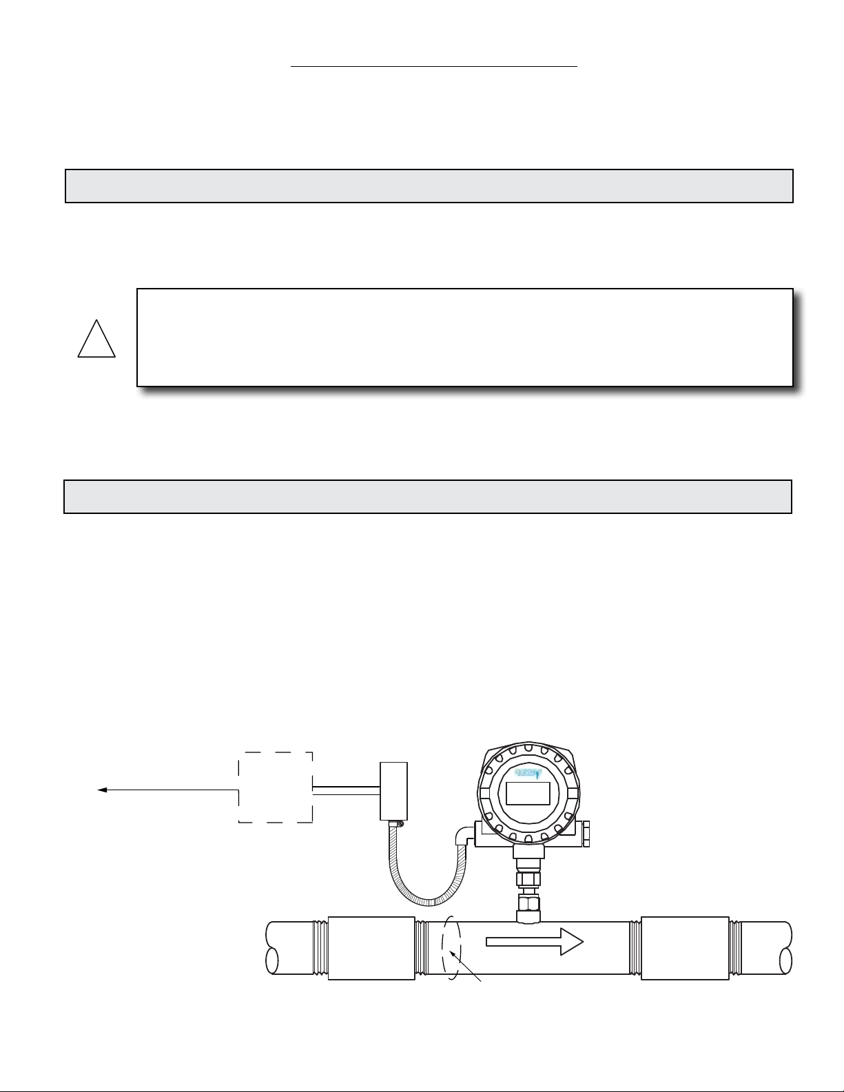
1.2 TYPICAL INLINE THERMAL MASS FLOW METER
Each ONICON thermal mass meter has a single pair of encapsulated platinum sensors that are
in direct contact with the gas. The sensors consist of highly stable reference-grade platinum
windings. One sensor is self-heated and serves as the ow sensor. The other acts as a reference
sensor, and measures the gas temperature. Our proprietary sensor circuitry maintains a constant
temperature differential between the ow sensor and the reference sensor.
As gas ows by the heated sensor (ow sensor), the molecules of owing gas carry heat away
and the sensor cools. The sensor circuitry continuously compensates for this cooling effect and
maintains a constant temperature differential between the two sensors. The energy required to
maintain this temperature differential is directly proportional to the mass ow. There is no need
for additional temperature or pressure compensation.
Output signal(s)
to control system
Optional
ONICON
Display
Clearwater, FL USA
F-5000 Series
www.onicon.com
Flow
Built-in flow conditioner
11451 Belcher Road South, Largo, FL 33773 • USA • Tel +1 (727) 447-6140 • Fax (727) 442-5699 • sales@onicon.com
F-5100 Inline Thermal Mass Flow Meter Manual 05/15 - 0686-11 / 18332 Page 5
Page 6

1.3 STANDARD FEATURES AND SPECIFICATIONS
CALIBRATION
Every ONICON thermal mass ow meter is wet calibrated in a ow laboratory against standards that are directly
traceable to N.I.S.T. A certicate of calibration accompanies every meter. Each meter is calibrated for use with a specic gas.
Standard Reference Conditions for Natural Gas: Standard Reference Conditions for Air:
Fluid: Methane Fluid: Air
Fluid Temperature: 60°F Fluid Temperature: 70° F
Fluid Pressure: 29.92” Hg (14.70 PSIA) Fluid Pressure: 29.92” Hg (14.70 PSIA)
Contact ONICON for reference conditions for other uid types.
ACCURACY
Natural Gas
± 1.0% of reading from 500 – 7000 SFPM
± 2.0 % of reading from 100 – 500 SFPM
Compressed Air
± 1.0 % of reading + 0.5% of scale over a
100:1 turndown
OVERALL FLOW RANGE
5 to 35,000 SFPM
SENSING METHOD
Thermal mass ow utilizing hybrid analog/digital sensing circuitry, no moving parts
INPUT POWER
Standard: 24 VDC ±10%, 100 mA maximum current
Optional: 90-265 VAC, 50/60 Hz
Optional: 12 VDC ±10%, 200 mA maximum current
FLUID TEMPERATURE RANGE
Standard: -40° to 200° F
Optional: 200° to 300° F
Optional: 300° to 450° F
Optional: 450° to 700° F
AMBIENT TEMPERATURE RANGE
-5° to 150° F
MAXIMUM OPERATING PRESSURE
Standard: 500 PSI
Optional: 1,000 PSI
MATERIALS OF CONSTRUCTION
Wetted metal components - 316L stainless steel
Sensor head - Platinum windings encapsulated in 316L stainless steel
Electronics enclosure - Powder coat painted cast aluminum
Remote mount enclosure - Cast aluminum
ENCLOSURE RATING
Weathertight, NEMA 4 (All versions)
APPROVALS
Integral and remote mount (24 VDC only) Class 1, Division 2, Groups B, C, & D,
(ATEX: Ex nA IIC T4X)
ELECTRICAL CONNECTIONS
Enclosed terminal blocks, cable access through two ½” NPT conduit ttings
PROGRAMMING / MEMORY
Factory programmed for specic application.
Non-volatile memory retains all program parameters and totalized values in the event of power loss.
OUTPUT SIGNAL(S)
Analog output: 4-20 mA
Scalable pulse output: Active 24 VDC pulse, 500ms duration
DISPLAY
Graphic OLED display indicates:
Bar graph indicating percentage of full scale ow
Flow rate: 7 digits
Flow total: 9 digits (Total rolls over to zero when maximum count is exceeded)
Fluid temperature: 3 digits
mWatts of energy used to heat ow sensor: 4 digits
Engineering units for rate and total
11451 Belcher Road South, Largo, FL 33773 • USA • Tel +1 (727) 447-6140 • Fax (727) 442-5699 • sales@onicon.com
F-5100 Inline Thermal Mass Flow Meter Manual 05/15 - 0686-11 / 18332 Page 6
Page 7
1.4 ADDITIONAL HARDWARE THAT MAY BE REQUIRED
i
1.4.1 Additional Remote Mount Cable
ONICON remote mount meters are provided with 25 ft of cable. Additional cable lengths
of up to 1000 ft may be added without affecting the calibration of the meter.
Part # Description
17350 25 ft of additional mount remote cable
17351 50 ft of additional remote mount cable
17352 100 ft of additional remote mount cable
1.4.2 Gaskets for Flanged Meters
For F-5100 Inline Thermal Mass Flow Meters provided with ANSI class 150 or class 300
anges require gaskets for proper installation. ONICON does not supply gaskets.
Gaskets used must comply with all relevant AGA and ANSI standards.
1.5 WORKING ENVIRONMENT
F-5000 series meters are designed for installation and use in typical industrial environments that
are free of corrosive liquids and fumes, direct liquid exposure, heavy condensation, temperature
extremes and vibrations. Do not install the meter in direct sunlight.
The operating ambient air temperature range is -5° to 150° F.
The electrical power should be relatively clean, free of high frequency noise, large voltage
transients, and protected from power surges and brown outs.
1.6 WARRANTY & SERIAL NUMBER
IMPORTANT NOTE
ONICON F-5000 series ow meters are individually calibrated. Remote mount electronics
enclosures and sensors must share the same serial number and must be installed together as a
system. Mixing components from different meters will result in signicant errors in calibration.
Warranty
ONICON provides a 2-year warranty for this product. Certain exclusions apply. Please refer to
Appendix A-2, ONICON’s Terms and Conditions of Sale for details.
Serial Number
The serial number of your F-5100 series ow meter is located on the nameplate attached to the
top of the enclosure. This serial number will also be located on the remote sensor for remote
mount meters.
11451 Belcher Road South, Largo, FL 33773 • USA • Tel +1 (727) 447-6140 • Fax (727) 442-5699 • sales@onicon.com
F-5100 Inline Thermal Mass Flow Meter Manual 05/15 - 0686-11 / 18332 Page 7
Page 8

SECTION 2.0: UNPACKING
ONICON Insertion Thermal Mass Flow Meters are packed and shipped in individual cartons. All other
peripheral devices will be packaged and shipped separately.
Please open all packages with care to prevent damage to their contents. Carefully inspect each item
for signs of damage in transit.
All ONICON products are shipped insured unless the customer specically requests otherwise. Please
notify the shipping company and ONICON Customer Service immediately if any items are damaged in
transit. Save all packing material for inspection by the shipper.
2.1 CHECKING TO SEE THAT YOU RECEIVED EVERYTHING
Standard Documentation
Enclosed with each meter is a comprehensive documentation package that includes the following
items:
• Installation and Operation Guide
• Flow Meter Calibration Certicate
• Product Data Sheet
• Scaled Pulse Isolator Module
Please notify the ONICON customer service department if any of these documents are missing.
Product
• F-5100 Inline Thermal Mass Flow Meter
11451 Belcher Road South, Largo, FL 33773 • USA • Tel +1 (727) 447-6140 • Fax (727) 442-5699 • sales@onicon.com
F-5100 Inline Thermal Mass Flow Meter Manual 05/15 - 0686-11 / 18332 Page 8
Page 9

SECTION 3.0: INSTALLATION
!
!
!
WARNING
This ow meter may be installed in pipes which are under high pressure or pipes lled with
combustible gases. Accidents with these systems can cause serious injury or death. Only persons
experienced with high pressure and/or combustible gas distribution systems and uid metering
should attempt to install, adjust, or remove the ow meter. Please read all instructions carefully
before attempting to install or service a ow meter.
ONICON will be happy to assist with technical recommendations and to provide guidance by phone
or e-mail. On-site eld engineering, installation and service are also available at an additional cost.
3.1 INSTALLATION SITE SELECTION
Install the ow meter where it will be accessible for personnel to perform necessary periodic
maintenance. The clearance required for installation is a minimum of 9” from the pipe wall
to the nearest obstruction above the electronics enclosure. Refer to Section 1.5 WORKING
ENVIRONMENT for additional considerations.
ONICON inline style ow meters must also be correctly oriented in the pipe with respect
to the direction of ow. On meters with an integrally mounted display, this will affect the
orientation of the display.
Flow
Flow
Flow
The drawings above illustrate the relationship between the integral display, the ow direction
and the orientation of the meter when installed in the pipe. Contact ONICON for assistance if
this relationship does not allow for viewing the display.
DO NOT LOOSEN
THESE FITTINGS
WARRANTY VOID
IF REMOVED
WARNING
11451 Belcher Road South, Largo, FL 33773 • USA • Tel +1 (727) 447-6140 • Fax (727) 442-5699 • sales@onicon.com
F-5100 Inline Thermal Mass Flow Meter Manual 05/15 - 0686-11 / 18332 Page 9
Page 10

GENERAL PRACTICES:
1. For best results, install the ow meter in a straight run of pipe, free of bends, tees,
valves, transitions and obstructions.
2. Straight run requirements vary based on the nature of the upstream obstruction.
See the table on page 12 for guidelines in determining upstream straight run
requirements. Depending upon specic location details, more or less straight run
may be required to produce a satisfactory ow prole.
3. If there is insufcient straight run, allow 80% of the run upstream and 20% of
the run downstream. If the total length of straight run is less than 75% of the
recommended distance, performance may seriously degrade.
How to Determine the Available Straight Pipe Run:
Locate the longest straight unobstructed section of pipe available. To be unobstructed, the
section of pipe must be free of bends, tees, size transitions, valves or insertion probes of
any kind.
In addition to the information provided above and on the
previous page, the diagrams shown below and the table
shown on the next page should be used as a guide to
identifying the best installation location for the meter.
Required upstream/downstream distances in inches
as measured from the process connections.
9"Minimum Height
Flow
Upstream
Downstream
EVALUATING UPSTREAM
PIPING CONDITIONS
Straight Pipe
Single Bend
Pipe Reduction
Multiple Bends in Same Plane
Pipe Expansions
Tees
Multiple Bends Out of Plane
Modulating or Regulating Valve
Worse Better
Flow
9"Minimum Height
Flow
Upstream
Downstream
Available Straight Run
Meter may be installed in a
vertical pipe with upward or
downward flow
11451 Belcher Road South, Largo, FL 33773 • USA • Tel +1 (727) 447-6140 • Fax (727) 442-5699 • sales@onicon.com
F-5100 Inline Thermal Mass Flow Meter Manual 05/15 - 0686-11 / 18332 Page 10
Page 11

Minimum Straight Run required upstream of ow meter process connection based on
i
the nature of the upstream obstruction.
Single bend
preceded by ≥ 9
Upstream
Obstructions
Nom. Dia.
¼” None 2.5” 2.5” 2.5” 2.5” None
⅜” 1.25” 3.75” 3.75” 3.75” 3.75” None
½” 1.5” 5” 5” 5” 5” None
¾” 2.25” 7.5” 7.5” 7.5” 7.5” 1”
1” 3” 10” 10” 10” 10” 1”
1¼” 3.75” 12.5” 12.5” 12.5” 12.5” 2”
1½” 4.5” 15” 15” 15” 15” 2”
2” 6” 20” 20” 20” 20” 4”
2½” 7.5” 25” 25” 25” 25” 7”
3” 9” 30” 30” 30” 30” 9”
4” 12” 40” 40” 40” 40” 12”
diameters of
straight pipe
Or
Pipe size
reduction in
straight pipe run
Multiple bends
in plane with
< 9 diameters
of straight pipe
between them
Or
Pipe size
expansion in
straight pipe run
Tees
Multiple
bends out
of plane
Modulating
or
Regulating
valves
Or
Roots or
Diaphram
Utility
Meters
Minimum Downstream
Straight Run Required
Process Connection
After Flow Meter
IMPORTANT NOTICE
Always use the maximum available straight run. When more than the minimum required straight
run is available place the meter such that the excess straight run is upstream of the meter location.
The ow meter must also be properly installed with respect to the direction of ow. Installing the
meter with the ow arrow pointing in the wrong direction will result in signicant errors in the
ow measurement.
11451 Belcher Road South, Largo, FL 33773 • USA • Tel +1 (727) 447-6140 • Fax (727) 442-5699 • sales@onicon.com
F-5100 Inline Thermal Mass Flow Meter Manual 05/15 - 0686-11 / 18332 Page 11
Page 12

D
L
H
3.2 MECHANICAL INSTALLATION
!
!
WARNING
DO NOT LOOSEN
THESE FITTINGS
WARRANTY VOID
IF REMOVED
ONICON Inline Thermal Mass Flow Meters are provided with either threaded of anged process
connections. Threaded meters are provided with male NPT threads and anged meters are
provided with ANSI class 150 or class 300 anges. Flow meters should be installed in accordance
with the requirements of section 3.1 INSTALLATION SITE SELECTION.
ONICON does not supply gaskets for anged meters.
Output signal(s)
to control system
Optional
ONICON
Display
Clearwater, FL USA
F-5000 Series
www.onicon.com
Flow
Built-in flow conditioner
3.2.1 Threaded Meter
D
H
Threaded inline sensor dimensions (inches)
L
¼ ⅜ ½ ¾ 1 1¼ 1½ 2 2½ 3 4
L 6 6 7 8 10 12 12 12 12 12 12
D 0.54 0.68 0.84 1.05 1.315 1.66 1.9 2.375 2.875 3.5 4.5
H 9.42 9.56 9.72 9.93 10.195 10.54 10.78 11.255 11.755 12.38 13.38
11451 Belcher Road South, Largo, FL 33773 • USA • Tel +1 (727) 447-6140 • Fax (727) 442-5699 • sales@onicon.com
F-5100 Inline Thermal Mass Flow Meter Manual 05/15 - 0686-11 / 18332 Page 12
Page 13

Installation Instructions
1. Apply AGA approved paste sealant or tape sealant to the male NPT threads.
2. Tighten ttings as per ANSI standards for NPT pipe ttings.
3. Leak test all connections.
3.2.2 Flanged Meter
H
D
L
ANSI Class 150 Flanged inline sensor dimensions (inches)
¼ ⅜ ½ ¾ 1 1¼ 1½ 2 2½ 3 4
L n/a n/a 7 8 10 12 12 12 12 12 12
D n/a n/a 3.5 2.88 4.25 4.62 5 6 7 7.5 9
H n/a n/a 12.38 12.76 13.13 13.5 13.88 14.88 15.88 16.38 17.88
ANSI Class 300 Flanged inline sensor dimensions (inches)
¼ ⅜ ½ ¾ 1 1¼ 1½ 2 2½ 3 4
L n/a n/a 7 7 8 10 12 12 12 12 12
D n/a n/a 3.75 4.62 4.88 5.25 6.12 6.5 7.5 8.25 10
H n/a n/a 12.63 13.5 13.76 14.13 15 15.38 16.38 17.13 18.88
Bolt pattern for 4”
anged meter
Bolt pattern for
½” - 3” anged meter
11451 Belcher Road South, Largo, FL 33773 • USA • Tel +1 (727) 447-6140 • Fax (727) 442-5699 • sales@onicon.com
F-5100 Inline Thermal Mass Flow Meter Manual 05/15 - 0686-11 / 18332 Page 13
Page 14

Installation Instructions
1. Thoroughly clean all ange surfaces removing all traces of any old gasket material
or any adhesive residue.
2. Inspect all ange surfaces for warping, pitting or other surface imperfections that
may prevent a good seal.
3. Use new bolts, nuts and hardened washers. Prior to installation,
lubricate the bolt threads, nuts, washer faces and the underside of each bolt head
with lubricant (Fel Pro C5A or equivalent). This lubricant is necessary to ensure
uniform stress distribution on the sealing surface. Use care not to get any
lubricant on the gasket material.
4. Center the new gasket on the ange face. Do not allow the gaskets to protrude into
the ow stream.
5. Use the torque specications provided by the gasket manufacturer to determine
the proper torque setting.
6. Using a torque wrench, tighten the bolts in at least three stages (30%, 60% &
100%) using a repeating pattern sequence of 12 o’clock to 6 o’clock to 3 o’clock to
9 o’clock around the ange as shown in the diagrams below.
7. Leak test all connections.
Bolt Tightening Sequence
11451 Belcher Road South, Largo, FL 33773 • USA • Tel +1 (727) 447-6140 • Fax (727) 442-5699 • sales@onicon.com
F-5100 Inline Thermal Mass Flow Meter Manual 05/15 - 0686-11 / 18332 Page 14
Page 15

!
!
!
i
3.3 ELECTRICAL INSTALLATION
The electrical installation of this product must comply with all federal, state and local building
codes. Connect and re-verify all output signal and safety earth wiring connections prior to
connecting power.
All connections must be made through the (2) ½’ NPT cable glands located on the enclosure.
To access the terminal wiring connections, remove the rear cover from the enclosure.
CAUTION
Cable glands seals shipped with the meter are for shipping purposes only. Remove and replace with
approved ttings when installing the meter.
WARNING
If the meter is being installed in a Class 1 hazardous location, the installation must comply with all
appropriate electrical codes.
WARNING
The meter must be connected to a protective earth wire at the transmitter and at the sensor for
remote mount meters as per electrical codes.
3.3.1 Analog Output
The F-5100 is provided with a single 4-20 mA output for instantaneous rate. This output is
electrically isolated from earth, but shares common with the scaled pulse output and, on
DC versions of the meter, with input power.
The output is programmed at the factory. Refer to the attached laminated tag or the
certicate of calibration for information regarding the programmed full scale ow.
Contact ONICON for assistance if the full scale ow rate requires reprogramming.
3.3.2 Pulse Output
The F-5100 is provided with a single scaled pulse output for totalizing ow. This is an
active pulse output with a nominal pulse amplitude of 24VDC (12VDC for 12V versions of
the meter). In all versions, the pulse duration is 500ms.
This DC pulse output is electrically isolated from earth, but shares common with the
analog output and, on DC versions of the meter, with input power. This output is
programmed at the factory. Refer to the attached laminated tag or the certicate of
calibration for information regarding the programmed pulse value.
Contact ONICON for assistance if the scaled pulse output requires reprogramming.
IMPORTANT NOTICE
The nominal pulse output voltage from this meter is 24 VDC. A pulse isolator module has been
provided with this meter that will convert this active pulse into an isolated dry contact output.
Refer to section 3.3.4 Using the Pulse Isolator Module for details.
11451 Belcher Road South, Largo, FL 33773 • USA • Tel +1 (727) 447-6140 • Fax (727) 442-5699 • sales@onicon.com
F-5100 Inline Thermal Mass Flow Meter Manual 05/15 - 0686-11 / 18332 Page 15
Page 16

3.3.3 Integral Mount Wiring
i
INSIDE REAR
COVER LABEL
A1 - RED - VELOCITY SENSOR WIRE (HEATED ELEMENT)
A2 - NO WIRE
A B C
1 RED AC1 COM 1
2
S1 AC2 B + 2
3
RED NU A – 3
4
WHITE NU 4
5
S2 4-20mA 5
6
WHITE SIG GND 6
INTEGRAL
TERMINAL BLOCK SIDE
VDC IN
+
VDC GND
–
24 VDC
PULSE
A3 - RED - VELOCITY SENSOR WIRE (HEATED ELEMENT)
A4 - WHITE - TEMPERATURE SENSOR WIRE
A5 - NO WIRE
A6 - WHITE - TEMPERATURE SENSOR WIRE
B1 - AC1 - AC VOLTAGE
B2 - AC2 - AC VOLTAGE
B3 - NU - NOT USED
B4 - 4 - 20 mA POWER
B5 - VDC IN - VOLTAGE DC - POSITIVE (+)
*
B6 - VDC GND - VOLTAGE DC - GROUND (-)
C1 - NOT USED
C2 - RS 485 (+)
C3 - RS 485 (-)
C4 - 24 VDC PULSE - 0 TO 24 DC PULSE OUTPUT
*
C5 - 4 - 20 mA - 4 TO 20 mA ANALOG OUTPUT
C6 - VDC GND - VOLTAGE DC - GROUND (-)
NO CUSTOMER ACCESS
DO NOT OPEN THIS SIDE
INSIDE BODY VIEW
A B C
1
2
3
4
5
6
1
2
3
4
5
6
USER ENTRY
FOR WIRING
½” NPT
½” NPT
USER ENTRY
FOR WIRING
(ONE ON EACH SIDE)
F-5100 Terminals
A B
C
1
2
3
4
5
6
A B
C
DISPLAY SIDE
1
2
3
4
5
6
Flow
*
Factory installed jumper and resistor.
Do not remove.
Control System
DC Pulse +
4-20mA +
+24 VDC
VDC Common
IMPORTANT NOTICE
The nominal pulse output voltage from this meter is 24 VDC. A pulse isolator module has been
provided with this meter that will convert this active pulse into an isolated dry contact output.
Refer to section 3.3.4 Using the Pulse Isolator Module for details.
11451 Belcher Road South, Largo, FL 33773 • USA • Tel +1 (727) 447-6140 • Fax (727) 442-5699 • sales@onicon.com
F-5100 Inline Thermal Mass Flow Meter Manual 05/15 - 0686-11 / 18332 Page 16
Page 17

F-5100 Terminals
Control System Enclosure
Scaled Pulse Isolator
Connection to F-5100
3.3.4 Using the Pulse Isolator Module
Scaled Pulse Isolator
Connection to F-5100
(Shown with Insertion Meter)
F-5100 Terminals
A B
C
Control System Enclosure
Control System
Analog / Pulse Inputs
1
2
3
4
5
6
A B
1
2
3
4
5
6
C
Scaled Pulse Isolator
Pulse Input
Non-polarized
Output
Field Wiring
The Pluse Isolator Module is designed to be mounted inside the control system enclosure. It
converts to active DC pulse output from the ow meter into an isolated dry contact closure
output. Using the pulse isolator does not change the pulse rate or duration.
11451 Belcher Road South, Largo, FL 33773 • USA • Tel +1 (727) 447-6140 • Fax (727) 442-5699 • sales@onicon.com
F-5100 Inline Thermal Mass Flow Meter Manual 05/15 - 0686-11 / 18332 Page 17
Page 18

3.3.5 Remote Mount Wiring
shown above
INSIDE REAR
COVER LABEL
A B C
1 RED AC
2
3
4
5
6
1
VDC IN
+
VDC GND
–
REMOTE
COM 1
24 VDC
PULSE
GREEN AC2 B + 2
BLUE NU A – 3
WHITE NU 4
BLACK 4-20mA 5
ORANGE SIG GND 6
TERMINAL BLOCK SIDE
½” NPT
USER ENTRY
FOR WIRING
(ONE ON EACH SIDE)
A1 - RED - VELOCITY SENSOR WIRE (HEATED ELEMENT)
A2 - GREEN - SENSE WIRE
A3 - BLUE - VELOCITY SENSOR WIRE (HEATED ELEMENT)
A4 - WHITE - TEMPERATURE SENSOR WIRE
A5 - BLACK SENSE WIRE
A6 - ORANGE - TEMPERATURE SENSOR WIRE
B1 - AC1 - AC VOLTAGE
B2 - AC2 - AC VOLTAGE
B3 - NU - NOT USED
B4 - 4 - 20 mA POWER
B5 - VDC IN - VOLTAGE DC - POSITIVE (+)
*
B6 - VDC GND - VOLTAGE DC - GROUND (-)
C1 - NOT USED
C2 - RS 485 (+)
C3 - RS 485 (-)
C4 - 24 VDC PULSE - 0 TO 24 DC PULSE OUTPUT
*
C5 - 4 - 20 mA - 4 TO 20 mA ANALOG OUTPUT
C6 - VDC GND - VOLTAGE DC - GROUND (-)
DISPLAY SIDE
NO CUSTOMER ACCESS
DO NOT OPEN THIS SIDE
INSIDE BODY VIEW
A B C
1
2
3
4
5
6
REMOTE CABLE
JUNCTION BOX
¾” NPT FOR
JUNCTION BOX
CONTAINS NO
ELECTRONICS,
JUST TERMINALS
1
2
3
4
5
6
½” NPT
USER ENTRY
FOR WIRING
¾” FNPT FOR
Conduit Connection
Factory installed jumper and resistor. Do not remove.
*
Remote Cable
Ground Screw
Metal conduit
is recommended
with appropriate
grounding to
minimize effects
from external
noise sources.
Interconnect Cable
Flow
Blue
Green
Red
Orange
Black
White
¾” NPT
conduit connection
To Terminal A1 to A6
11451 Belcher Road South, Largo, FL 33773 • USA • Tel +1 (727) 447-6140 • Fax (727) 442-5699 • sales@onicon.com
F-5100 Inline Thermal Mass Flow Meter Manual 05/15 - 0686-11 / 18332 Page 18
Page 19

SECTION 4.0: START-UP & COMMISSIONING FOR ONICON
4.1 DISPLAY
INLINE THERMAL MASS FLOW METERS
The F-5100 ow meter features a bright easy-to-read
graphic LED display that displays alphanumeric and
graphical data.
This display is provided with a screen saver function
that extends the life of the display. The display will
revert to the normal display mode whenever the
proximity sensor detects movement directly in front
of the meter.
Displayed Information:
1. Energy reading used to valid calibration
2. Graphical indication of percentage of full
scale ow rate
3. Flow rate
4. Flow total
5. Fluid temperature
6. Engineering units associated with ow rate and total
7. LED’s for Power, Serial Communications, and Pulse Output
4.2 POWERING THE METER
1
2
3
5
7
6
4
Upon initial power up, the meter will indicate ONICON F-5000 Series along with the current
rmware version and the serial number. Two additional messages will be displayed and then the
meter will advance to the normal run mode screen. If the meter is installed in a pipe with ow,
the meter will begin displaying ow and temperature data. After one minute of no movement,
the screen saver message will appear.
4.3 HELPFUL HINTS FOR START-UP & COMMISSIONING
A step-by-step procedure and companion worksheet are located on the next two pages. Please
read all installation instructions carefully before proceeding with start-up and commissioning.
Please read these helpful hints before proceeding with the start-up and commissioning procedure
on the next page.
1. When measuring analog output signals, remember that current (mA) must be measured
in series, while voltage is measured in parallel. If the 4-20 mA signal is already connected
to a control system, you must break the connection and measure the signal in series.
2. Do not attempt to rotate the electronics enclosure on the stem.
3. Never connect power to analog or pulse output signal wires. Standard ONICON F-5100
Flow Meters are not congured from the factory as “loop powered” devices.
11451 Belcher Road South, Largo, FL 33773 • USA • Tel +1 (727) 447-6140 • Fax (727) 442-5699 • sales@onicon.com
F-5100 Inline Thermal Mass Flow Meter Manual 05/15 - 0686-11 / 18332 Page 19
Page 20

4.4 START-UP & COMMISSIONING
Please read the entire procedure before proceeding. A worksheet for checking off the following
steps and recording measured values is located on the next page.
1. Conrm ow meter location.
Conrm adequate straight pipe run
to achieve desired results.
2. Conrm orientation. Refer to the information in section 3.1 of this manual to ensure
3. Conrm control system
programming.
4. Conrm connection to
correct ONICON display
5. Verify wiring before connecting
power.
6. Conrm correct supply voltage. Verify that the supply voltage matches the voltage listed on the
7. Connect power. Wait approximately 45 seconds after power-on before proceeding
Is the meter located in the correct location as required by the plans?
Compare actual straight pipe upstream and downstream of the meter location to recommended distances identied in this manual.
that the meter is properly oriented with respect to the direction of
ow.
Conrm that the control system input point is properly congured
for the analog range and/or scale factor identied on the calibration
tag
& certicate.
Conrm that the ow meter serial number matches the ONICON
display (when ordered together).
Prior to connecting the power, verify that the wiring is correct as
shown in this manual and/or on additional wiring diagrams provided with the ONICON display. If in doubt, contact ONICON for
assistance before proceeding further.
meter tag.
further.
The following steps require ow in the pipe. Flow signal readings should be taken while
holding the ow rate constant, if possible. Otherwise, take the various output readings as
quickly as possible.
8. Measure and record analog and
pulse outputs.
Refer to ow meter wiring diagram to locate the correct output
terminals. Use the following formula to calculate the ow rate from
the analog signal measurement:
Current Output:
Scaled Output:
9. Compare output signals to each
other and to the ow rate displayed
by the control system.
11451 Belcher Road South, Largo, FL 33773 • USA • Tel +1 (727) 447-6140 • Fax (727) 442-5699 • sales@onicon.com
F-5100 Inline Thermal Mass Flow Meter Manual 05/15 - 0686-11 / 18332 Page 20
SCFM = (measured current in mA - 4) X Full Scale Flow Rate
16
Each 24VDC pulse = unit volume identied as “Scale Factor” (measure and record time interval between pulses)
Compare the ow rate calculated in step 8 to the ow rate indicated
by the control system. Conrm that the control system is registering
scaled output pulses as they occur.
Refer to troubleshooting guide when readings are inconsistent.
Page 21

4.5 START-UP & COMMISSIONING WORKSHEET
Please read all installation instructions carefully prior to proceeding with these steps. Use the
following worksheet for checking off the commissioning steps and recording measured values.
STEP TEST/MEASUREMENT S/N: S/N: S/N: S/N:
1. Meter location:
2. Conrm pipe size:
3. Conrm orientation:
4. Control system
programming:
5. Match display
serial number
(S/N) if ordered:
6. Signal connections
veried:
7. Supply voltage veried:
8. Connect power:
The following steps require ow in the pipe. Flow signal readings should be taken while
holding the ow rate constant, if possible. Otherwise, take the various output readings as
quickly as possilbe.
9. Analog or pulse
output(s)
__________mA
4 - 20 mA signal:
____________
Scaled output interval:
_______SCFM
Calculated ow rate:
10. Flow rate displayed by
control system: _______SCFM _______SCFM _______SCFM _______SCFM
__________mA
____________
_______SCFM
__________mA
____________
_______SCFM
__________mA
____________
_______SCFM
11451 Belcher Road South, Largo, FL 33773 • USA • Tel +1 (727) 447-6140 • Fax (727) 442-5699 • sales@onicon.com
F-5100 Inline Thermal Mass Flow Meter Manual 05/15 - 0686-11 / 18332 Page 21
Page 22

SECTION 5.0: TROUBLESHOOTING GUIDE
NOTE: Also refer to the START-UP AND COMMISSIONING GUIDE located on page 19.
REPORTED PROBLEM POSSIBLE SOLUTIONS
No signal • Verify that the meter is properly installed in the pipe.
• Verify that the ow direction arrow is pointing in the right direction.
• Verify supply voltage.
• Verify correct wiring to control system (see wiring diagram).
• Verify that there is ow in the pipe.
• Please contact ONICON for further assistance.
Reading is too high or
low
Erratic readings • Conrm that the meter is connected to earth and all cabling is
• Verify that the meter is properly installed in the pipe.
• Verify that the ow direction arrow is pointing in the right direction.
• Verify correct wiring to control system (see wiring diagram).
• Conrm that the control system is programmed for correct ow range
or pulse scale factor.
• Verify that the meter cable shield is connected to earth at the control
system. Lack of proper shielding can lead to excessive noise that can
affect the ow reading.
• Verify that the meter is connected to earth.
• Check for ground loop or offset voltage: Disconnect analog signal
input from control system and measure analog output directly from
the ow meter. Reconnect signal input to control system and measure
the analog signal again. Any difference between these readings
indicates a potential ground loop or offset voltage.
• Meter is being used to measure ow of a different gas or gas mix than
the meter was specied and calibrated for.
• Please contact ONICON for further assistance.
properly shielded.
• Please contact ONICON for further assistance.
11451 Belcher Road South, Largo, FL 33773 • USA • Tel +1 (727) 447-6140 • Fax (727) 442-5699 • sales@onicon.com
F-5100 Inline Thermal Mass Flow Meter Manual 05/15 - 0686-11 / 18332 Page 22
Page 23

APPENDIX
A-1 REMOTE MOUNT MECHANICAL HARDWARE
A-2 CONDITIONS OF SALE
11451 Belcher Road South, Largo, FL 33773 • USA • Tel +1 (727) 447-6140 • Fax (727) 442-5699 • sales@onicon.com
F-5100 Inline Thermal Mass Flow Meter Manual 05/15 - 0686-11 / 18332 Page 23
Page 24

REMOTE MOUNT MECHANICAL HARDWARE
11451 Belcher Road South, Largo, FL 33773 • USA • Tel +1 (727) 447-6140 • Fax (727) 442-5699 • sales@onicon.com
F-5100 Inline Thermal Mass Flow Meter Manual 05/15 - 0686-11 / 18332 Page A-1
Page 25

CONDITIONS OF SALE
1. ACCEPTANCE: The following Conditions of Sale apply to all sales of ONICON’s products. These provisions shall apply even
if ONICON fails to object to provisions appearing on, incorporated by, referenced in, or attached to Buyer’s purchase order
form. Buyer’s acceptance of delivery of ONICON’s products constitutes its acceptance of these Conditions of Sale.
2. DELIVERY AND TITLE: All product shipments are Ex Works shipping point and title passes to the Buyer at the time ONICON
delivers the merchandise to the carrier. Risk of loss or damage to the product passes to the Buyer at the time ONICON delivers
the product to the carrier. The Buyer immediately upon receipt should inspect all shipments, and should there be any evidence of
damage or loss in transit, Buyer must le claims or tracers upon carrier. ONICON will assist in tracing shipments upon request.
3. LIMITED WARRANTY: ONICON warrants that for a period of two (2) year following the date of original shipment of an
ONICON product: (i) the product will conform to ONICON’s standard written specications applicable to such product in effect
on the date of Buyer’s order, or as modied by ONICON’s quotation or Buyer’s purchase order accepted by ONICON, (ii) the
product will be free from defects in workmanship, and (iii) that ONICON has title to the product prior to shipment to the Buyer;
provided, however, that the warranties provided herein shall be void and may not apply in the event Buyer misuses or
damages a product, including, but not limited to, any use by the Buyer of a product for an application other than one of a type
approved by ONICON. ONICON’s sole liability and Buyer’s sole remedy for any breach of the foregoing warranty is for
ONICON to repair or replace, at ONICON’s option, any defective product that is returned to ONICON during the warranty
period. EXCEPT AS MAY BE SPECIFICALLY AGREED BY ONICON IN WRITING IN RELATION TO EACH SALE, NO
OTHER WARRANTIES SHALL APPLY, WHETHER EXPRESSED, IMPLIED OR STATUTORY, AND THERE SHALL BE NO
IMPLIED WARRANTIES OF MERCHANTABILITY AND FITNESS FOR A PARTICULAR PURPOSE.
4. REMEDIES: ONICON’s OBLIGATION UNDER THE FOREGOING WARRANTIES IS LIMITED SOLELY TO REPAIR OR
REPLACEMENT, AT ONICON’s OPTION, OF DEFECTIVE OR NONCONFORMING PRODUCTS. ONICON SHALL NOT BE
LIABLE FOR CONSEQUENTIAL, INDIRECT, PUNITIVE, INCIDENTAL, OR SPECIAL DAMAGES WHETHER FOUND ON
CONTRACT, TORT OR ANY OTHER THEORY OF LAW. No products shall be returned to ONICON without its prior consent
and transportation and insurance costs shall be prepaid. Any repair or replacement of ONICON’s products under the foregoing
warranty will be at no charge to the Buyer provided such repair is done at the ONICON factory or authorized service center.
ONICON products that are repaired or replaced under this warranty will be returned to Buyer via the same method of shipment
use to return the product to ONICON. Repair or replacement of ONICON products is conditioned upon ONICON’s
acknowledgement of any alleged defect or nonconformance during the warranty period and issuance of a Return
Authorization number. All product returns must reference the Return Authorization number on the outside of the shipping
carton and on any paperwork referencing the return.
5. PRICES AND PAYMENT TERMS: The prices set forth in the most recent quote or acknowledgement as applicable, supersede
all previous prices or quotations. All quotations are subject to change or withdrawal without notice except as may be specically
noted on the face of the quotation. The prices shown do not include sales, excise or government charges payable by ONICON to
Federal, State, or local authority. Any such tax or charge now or hereafter imposed upon the sale or shipment of the products
under this contract will be added to the purchase price. Buyer agrees to reimburse ONICON for such tax or charge or provide
ONICON with an acceptable exemption certicate. Payment of invoices will be due 30 days from the date of shipment of the
products contained therein. In the event that payment of an invoice is not received by the invoice due date, ONICON will assess
a late fee not to exceed 1.5% per month or 18% per year, or the maximum allowable by law whichever is lower.
6. CANCELLATION: Buyer may cancel its order, or any part of it, by sending written notice of cancellation to ONICON and
paying a reasonable cancellation fee as determined by ONICON. The reasonable cancellation fee will reect, among other
factors, the expenses already incurred and commitments made by ONICON, sales and administrative costs and prot as
determined by ONICON. If Buyer received a reduced price based on the quantity of products ordered, but has not purchased
the applicable quantity at the time of cancellation, Buyer will pay the price it would have paid had ONICON’s sale price been
based on the quantity actually purchased.
7. CHANGES: If Buyer makes any changes in its drawings, designs, or specications applicable in any contract with ONICON
that cause an increase or decrease in the cost of performance of the contract, or if such changes result in rework or obsolescence, an
equitable adjustment shall be made to the contract. Such changes are subject to ONICON’s prior written consent.
8. EXCUSABLE DELAY: ONICON shall under no circumstance be responsible for failure to ll any order or orders when due to: res,
oods, riots, strikes, freight embargoes or transportation delays, shortage of labor, inability to secure fuel, material supplies, or power
at current price or on account of shortages thereof, acts of God or of the public enemy, any existing or future laws or acts of the
Federal or State Government (including specically, but not exclusively, and orders, rules or regulations issued by any ofcial or
agency of any such government) affecting the conduct of ONICON’s business with which ONICON in its judgment and discretion
deems it advisable to comply as a legal or patriotic duty, or due to any cause beyond ONICON’s reasonable control.
9. PATENTS: ONICON shall defend all suits or proceedings brought against Buyer or its customers arising from claimed
infringements of any patent, trademark, service mark or copyright for any product furnished by ONICON and shall indemnify it
against all costs, fees, and damages on the condition Buyer promptly noties ONICON in writing and provides information and
assistance to enable ONICON to conduct the defense, provided that ONICON shall have no such obligation in case of
infringement resulting from ONICON’s conformance to special requirements of Buyer. If ONICON is not able to settle any such
suit or proceeding on acceptable terms, ONICON may, at its option, require return of the infringing product and refund the
purchase price to Buyer less a reasonable allowance for depreciation or use.
10. FAIR LABOR STANDARDS ACT: ONICON represents that all products delivered under this contract are furnished in
accordance with the applicable provisions of the Fair Labor Standards Act as amended.
11. APPLICABLE LAW: This document and any resulting contract shall be governed by and construed in accordance with the
laws of the State of Florida. The courts of the State of Florida and the federal courts located in Florida shall have jurisdiction
and venue with respect to litigation to this contract. In the event of litigation, the prevailing party shall be entitled to recover
attorney’s fees and costs from the non-prevailing party, including appellate attorney’s fees.
12. MODIFICATIONS: These Conditions of Sale along with the prices, quantities, delivery schedules and other provisions and
instructions in applicable quotations by ONICON or Buyer’s purchase orders accepted by ONICON shall constitute the entire
agreement between ONICON and Buyer pertaining to any resulting contract. They can be modied only in writing.
11451 Belcher Road South, Largo, FL 33773 • USA • Tel +1 (727) 447-6140 • Fax (727) 442-5699 • sales@onicon.com
F-5100 Inline Thermal Mass Flow Meter Manual 05/15 - 0686-11 / 18332 Page A-2
 Loading...