

Page 1
F-4300 Clamp-on Ultrasonic Flow Meter
FLOW AND ENERGY MEASUREMENT
Installation & Operation Guide
11451 Belcher Road South, Largo, FL 33773 • USA • Tel +1 (727) 447-6140 • Fax +1 (727) 442-5699
www.onicon.com • sales@onicon.com
06-172056-2 / 37515
Page 2
SAFETY INFORMATION
!
!
i
This meter was calibrated at the factory before shipment. To ensure correct use of the meter, please
read this manual thoroughly.
Regarding this Manual:
• This manual should be passed on to the end user.
• Before use, read this manual thoroughly to comprehend its contents.
• The contents of this manual may be changed without prior notice.
• All rights reserved. No part of this manual may be reproduced in any form without
ONICON’s written permission.
• ONICON makes no warranty of any kind with regard to this material, including, but not
limited to, implied warranties of merchantability and suitability for a particular purpose.
• All reasonable effort has been made to ensure the accuracy of the contents of this manual.
However, if any errors are found, please inform ONICON.
• ONICON assumes no responsibilities for this product except as stated in the warranty.
• If the customer or any third party is harmed by the use of this product, ONICON assumes
no responsibility for any such harm owing to any defects in the product which were not
predictable, or for any indirect damages.
Safety Precautions:
The following general safety precautions must be observed during all phases of installation,
operation, service, and repair of this product. Failure to comply with these precautions or with
specic WARNINGS given elsewhere in this manual violates safety standards of design,
manufacture, and intended use of the product. ONICON Incorporated assumes no liability for the
customer’s failure to comply with these requirements. If this product is used in a manner not
specied in this manual, the protection provided by this product may be impaired.
The following symbols are used in this manual:
WARNING
Messages identied as “Warning” contain information regarding the personal safety of individuals
involved in the installation, operation or service of this product.
CAUTION
Messages identied as “Caution” contain information regarding potential damage to the product or
other ancillary products.
Messages identied as “Important Note” contain information critical to the proper operation of the
product.
11451 Belcher Road South, Largo, FL 33773 • USA • Tel +1 (727) 447-6140 • Fax +1 (727) 442-5699 • sales@onicon.com
F-4300 Series Clamp-on Ultrasonic Flow Meter Manual 06/17 - 2056-2 / 37515 Page 2
IMPORTANT NOTE
Page 3

TABLE OF CONTENTS
1.0 INTRODUCTION .................................................................................................5
1.1 PURPOSE OF THIS GUIDE ...................................................................... 5
1.2 PRINCIPLE OF OPERATION .................................................................... 5
1.3 TYPICAL F-4300 FLOW METER ..............................................................5
1.4 STANDARD FEATURES AND SPECIFICATIONS ................................... 6
1.5 MAINTENANCE ........................................................................................7
1.6 ADDITIONAL HARDWARE THAT MAY BE REQUIRED .........................7
1.7 WORKING ENVIRONMENT ....................................................................7
1.8 WARRANTY AND SERIAL NUMBER .....................................................7
2.0 UNPACKING ...................................................................................................... 8
2.1 CHECKING THAT YOU HAVE RECEIVED EVERYTHING ..................... 8
3.0 INSTALLATION ................................................................................................... 9
3.1 OVERVIEW ...............................................................................................9
3.2 SITE SELECTION .....................................................................................10
3.3 MECHANICAL INSTALLATION ............................................................. 12
3.3.1 Mounting the Enclosure ............................................................ 12
3.3.2 Preparing the Pipe .....................................................................13
3.3.3 4 or 2 Cross Reect Mounting Using
Frames and Spacer Bar .............................................................. 13
3.3.4 1 Cross Mode Direct Mounting Using
Brackets and Spacer Bar ............................................................ 14
3.3.5 Installing Transducers in Bracket and Spacer Bar Hardware ..16
3.4 CONNECTING THE TRANSDUCER SIGNAL CABLES ........................18
3.5 ELECTRICAL INSTALLATION ...............................................................19
3.5.1 Input Power Options .................................................................19
3.5.2 Electrical Connections ............................................................... 20
3.5.2.1 Connections for Meters Powered by 100-240 VAC .....20
3.5.2.1 Connections for Meters Powered by 10-30 VAC/VDC 21
4.0 START-UP .................................................................................................... 22
4.1 NAVIGATING THE RUN MODE & PROGRAMMING PAGES ................ 22
4.2 RUN MODE & PROGRAMMING PAGE LAYOUT ..................................23
4.3 RUN MODE ICONS ..................................................................................24
4.4 RUN MODE PAGES .................................................................................24
4.5 PROGRAMMING MENU PAGES.............................................................26
11451 Belcher Road South, Largo, FL 33773 • USA • Tel +1 (727) 447-6140 • Fax +1 (727) 442-5699 • sales@onicon.com
F-4300 Series Clamp-on Ultrasonic Flow Meter Manual 06/17 - 2056-2 / 37515 Page 3
Page 4

5.0 BACNET MS/TP .................................................................................................32
5.1 BACnet OBJECT TYPES ..........................................................................32
5.2 PROTOCOL IMPLEMENTATION STATEMENT ....................................32
5.3 DEVICE OBJECT .....................................................................................33
5.4 ANALOG INPUT(S) ................................................................................. 34
5.5 ANALOG VALUE(S) ................................................................................35
5.6 BINARY VALUE(S) ................................................................................. 36
5.7 MULTI STATE VALUE .............................................................................37
6.0 MODBUS ....................................................................................................38
6.1 MODBUS MEMORY MAP ....................................................................... 39
6.2 REPORT SLAVE ID FUNCTION CODE ...................................................40
7.0 COMMISSIONING FOR ONICON CLAMP-ON
ULTRASONIC FLOW METERS..........................................................................41
7.1 HELPFUL HINTS FOR START-UP AND COMMISSIONING .................41
7.2 COMMISSIONING PROCEDURE ............................................................ 41
7.3 COMMISSIONING WORKSHEET ........................................................... 42
8.0 TROUBLESHOOTING ........................................................................................ 43
APPENDIX
A-1 SONIC VELOCITY RELATIVE TO TEMPERATURE OF PURE WATER
A-2 F-4300 MOTHER BOARD AC
A-3 F-4300 MOTHER BOARD DC
A-4 CONDITIONS OF SALE
11451 Belcher Road South, Largo, FL 33773 • USA • Tel +1 (727) 447-6140 • Fax +1 (727) 442-5699 • sales@onicon.com
F-4300 Series Clamp-on Ultrasonic Flow Meter Manual 06/17 - 2056-2 / 37515 Page 4
Page 5
SECTION 1.0: INTRODUCTION
1.1 PURPOSE OF THIS GUIDE
The purpose of this guide is to provide installation and commissioning procedures and basic
operating and servicing instructions for the ONICON F-4300 Clamp-on Ultrasonic Flow Meter.
1.2 PRINCIPLE OF OPERATION
The ONICON F-4300 Clamp-on Ultrasonic Flow Meter utilizes the differential transit time
method to measure the velocity of relatively clean liquids in full pipes. By measuring the
difference between transit times of ultrasonic sound waves travelling between two transducers,
the ow velocity and direction are accurately determined.
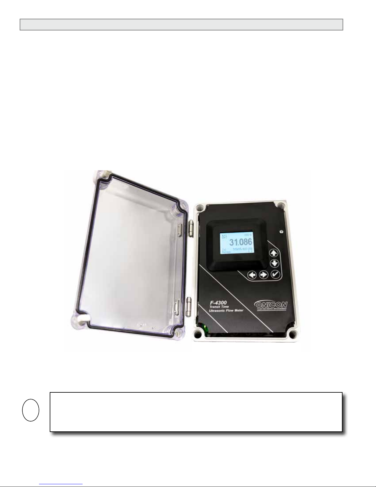
1.3 TYPICAL F-4300 FLOW METER
The F-4300 Ultrasonic Flow Meter utilizes clamp-on signal transducers that mount on the outside
wall of the pipe. It is suitable for measuring the volumetric ow of liquids in a wide variety of
applications including bi-directional ow applications. The meter is housed in a polycarbonate
wall-mounted enclosure with a built-in user interface/display.
TYPICAL INSTALLATION
Horizontal pipes: Install transducers
at 2 or 10 o’clock position
Vertical Pipes: Install transducers at
any position
Triaxial
Transducer
Cables
F-4300
Transit Time
Ultrasonic Flow Meter
Conduit-ready
Fittings
Mounting Hardware
11451 Belcher Road South, Largo, FL 33773 • USA • Tel +1 (727) 447-6140 • Fax +1 (727) 442-5699 • sales@onicon.com
F-4300 Series Clamp-on Ultrasonic Flow Meter Manual 06/17 - 2056-2 / 37515 Page 5
Page 6

1.4 STANDARD FEATURES AND SPECIFICATIONS
• Wall-mounted NEMA 4X polycarbonate enclosure with backlit alphanumeric user interface/display
• One internally powered electrically isolated 4-20 mA analog output for ow rate or ow velocity.
• Two scalable electrically isolated dry contact pulse output for totalizing ow, indicating ow
direction or ow alarm.
GENERAL SPECIFICATIONS
ACCURACY
± 1.0% of reading from 1 to 20 ft/sec
± 0.01 ft/s for velocities below 1 ft/sec
OVERALL FLOW RANGE
0.1 to 20 ft/sec
SENSING METHOD
Clamp-on ultrasonic, differential transit time
method indirect or reect mode
PIPE SIZE RANGE
2” through 24” nominal diameter
PROGRAMMING
Factory programmed for specic application
MEMORY
Non-volatile memory retains all program
parameters and totalized values in the event of
power loss.
DISPLAY
White, backlit alphanumeric display shows:
5-digit ow rate with oating decimal, 14-digit
totalizer, pulse output status, operating status,
and provides eld conguration.
Displays total ow, ow rate, ow velocity,
signal strength, ow direction, alarm
conditions, relay status & logger status
Rate display range: 0 - 9,999,999
Totalizer display range: 0 – 99,999,999
Totalizers will roll over to zero when maximum
count is exceeded.
OUTPUT SIGNALS PROVIDED
Analog output: Isolated 4-20 mA/0-5 VDC
(Internally powered, 1000Ω max impedance
eld, selectable)
Two Programmable pulse outputs:
Optically isolated dry contacts
Contact rating: 30 VDC, 10 mA maximum
Pulse duration: 50 ms
Programmable for scaled pulse, ow direction, or
ow alarm
Serial communications: BACnet® MS/TP or
FLUID TEMPERATURE RANGE
Standard: -40° F to 250° F
AMBIENT OPERATING TEMPERATURE RANGE
-5° F to 140° F
MECHANICAL
MATERIALS OF CONSTRUCTION
Electronics enclosure: Wall-mount, polycarbonate
with clear, shatter proof enclosure
Transducer mounting hardware: Anodized aluminum and
stainless steel
Transducers: Stainless Steel and plastic
ENCLOSURE RATINGS
NEMA 4X, weather tight
ELECTRICAL
This equipment is intended for INSTALLATION
CATEGORY (OVERVOLTAGE CATEGORY) II applications.
Installations must comply with all local, state and federal
building codes.
INPUT POWER – Factory selectable
10 - 30 VDC/VAC, 10 VA maximum
(Fuse not eld replaceable)
100 - 240 VAC 50/60 Hz, 10 VA maximum
(Internal: 5x20mm, 250V/2.0A fuse)
ELECTRICAL CONNECTIONS
Enclosed terminal connections, cable access through
three standard ½” conduit openings & one standard
¾” conduit opening
Transducer signals: (2) BNC-connectors
Input power: 2 terminal removable connector
(12 – 28 AWG)
Signal inputs/outputs: Removable connectors, 2 or 3
terminal (12 – 28 AWG)
WIRING
Transducer signals: Only use ONICON provided triaxial cable.
24 VDC/VAC input power: Use PVC jacketed copper cable
with a wire gauge suitable for the length of run and
required maximum current carrying capacity.
Provide a separate protective earth wire.
120/230 VAC input power: Use a 3-wire service
with one wire a protective earth ground.
Signal inputs/outputs: Use PVC jacketed copper
shielded cable with a wire gauge suitable for the
length of run and required maximum current
carrying capacity.
11451 Belcher Road South, Largo, FL 33773 • USA • Tel +1 (727) 447-6140 • Fax +1 (727) 442-5699 • sales@onicon.com
F-4300 Series Clamp-on Ultrasonic Flow Meter Manual 06/17 - 2056-2 / 37515 Page 6
Page 7

1.5 MAINTENANCE
Periodically inspect the power cables, transducer cables, cable glands and the enclosure for signs
of damage. Inspect transducer installation and mounting hardware for loose connections, or
diminished ultrasonic couplant.
1.6 ADDITIONAL HARDWARE THAT MAY BE REQUIRED
Flex conduit may be required to connect transducer mounting bracket to rigid conduit. Do not
connect transducers mounting brackets to rigid conduit.
1.7 WORKING ENVIRONMENT
The F-4300 was designed for installation and use in typical commercial/industrial environments.
The following considerations must be observed in selecting a location for the meter:
• The ambient operating temperature range is -5° F (-20° C) to 140° F (60° C).
• Do not expose the meter to corrosive liquids or fumes.
• Avoid installation locations that are close to strong sources of electrical interference.
• Avoid installing the electronics enclosure in direct sunlight.
• Avoid installation locations where the transducers will be exposed to vibrations in the
piping system.
• Always run transducer cables in dedicated conduit separate from signal and power cables.
• Do not run signal cables for the meter in conduit with mains (AC) power cables.
1.8 WARRANTY & SERIAL NUMBER
Warranty
ONICON provides a 2-year warranty for this product. Certain exclusions apply. Please refer to
ONICON’s Conditions of Sale for details.
Serial Number
The serial number of your F-4300 is located outside and inside the enclosure. Transducers will
be packaged inside the enclosure they were calibrated with, and will bear their own unique serial
numbers. You should have one of these serial numbers available when contacting ONICON for
assistance regarding your meter.
11451 Belcher Road South, Largo, FL 33773 • USA • Tel +1 (727) 447-6140 • Fax +1 (727) 442-5699 • sales@onicon.com
F-4300 Series Clamp-on Ultrasonic Flow Meter Manual 06/17 - 2056-2 / 37515 Page 7
Page 8
SECTION 2.0: UNPACKING
i
The F-4300 is generally shipped in one package. Notify the freight carrier (all products are shipped
insured) and ONICON if any items are damaged in transit.
2.1 CHECKING THAT YOU HAVE RECEIVED EVERYTHING
• Standard Documentation
Enclosed with each F-4300 is a comprehensive documentation package that includes the
following items:
This F-4300 Ultrasonic Flow Meter Installation and Operation Guide
The Flow Meter Certicate of Calibration
Site Installation Details Document
Please notify ONICON if any of these items are missing.
IMPORTANT NOTE
The ONICON F-4300 Ultrasonic Flow Meter is a custom calibrated system. Unless specically noted
in writing by ONICON, ALL COMPONENTS (electronics enclosure and ultrasonic transducers) share
associated serial numbers, and must be installed together as a system. Mixing components from
different systems will result in signicant errors in measurement.
• The Wall Mount Enclosure
Remove the F-4300 enclosure from the shipping carton and inspect it inside and out for
physical damage. Please notify ONICON immediately if you discover any damage.
Transducers are shipped inside the enclosure. Inspect the transducers for signs of damage.
Each transducer will have a label attached with a serial number associated with that found on
the F-4300 enclosure.
• Transducers Cables
Transducer cables are coiled and included inside the shipping carton. One end of each cable
is already terminated with a BNC connector for connection to the transducers. The other end
is pre-terminated for connection to the electronics. An easily removable strain-relief tting is
also included.
• Installation Hardware
Installation hardware includes mounting brackets and a spacer bar. Also included with this
hardware will be a mounting strap kit. This kit includes the mounting straps used to secure
the hardware onto the pipe. The shipping carton will also include a copy of the F-4300 Site
Installation Details for this meter. This document provides specic details such as transducer
spacing distance. This information is unique to the specic installation site and is identied
by the meter location tag name and the serial number of the meter. Included with the
installation hardware is one tube of coupling compound.
11451 Belcher Road South, Largo, FL 33773 • USA • Tel +1 (727) 447-6140 • Fax +1 (727) 442-5699 • sales@onicon.com
F-4300 Series Clamp-on Ultrasonic Flow Meter Manual 06/17 - 2056-2 / 37515 Page 8
Page 9
SECTION 3.0: INSTALLATION
3.1 OVERVIEW
Each F-4300 Ultrasonic Flow Meter is provided with a pair of matched ultrasonic transducers.
The transducers are mounted (clamped) on to the outside wall of the pipe. Triaxial cables convey
the transducer signals to the wall mount enclosure containing the signal processing circuitry
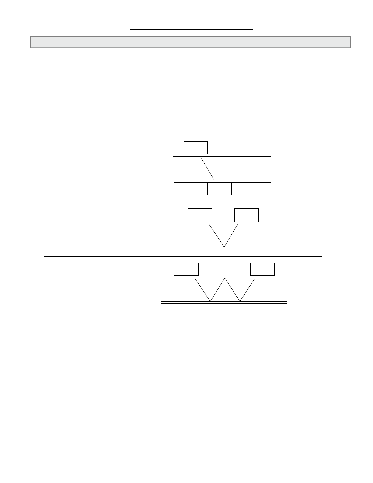
and the user interface display. Ultrasonic transducers can be congured to operate in either 4,
2 (Reect) or 1 (Direct) cross operating modes. The choice of operating mode is dictated by the
conguration settings programmed into the meter. For new installations, conguration data is
programmed into the meter prior to shipment. Programming data determines the transducer
operating mode and the spacing between the transducers. This information is provided with the
installation hardware in a document titled, “F-4300 Site Installation Details”.
1 Cross Z or (Direct)
2 Cross V or (Reect)
4 Cross W or (Double Reect)
4 or 2 Cross Mode (Reect)
4 or 2 cross mount is the recommended operating mode whenever possible. It is the simplest way
to mount the transducers. Operating in the reect mode also minimizes the effects of some ow
distortions.
1 Cross Mode (Direct)
1 cross mount provides a shorter sonic beam path. This usually improves performance with
sonically attentive liquids or pipe materials. Direct mounting only requires half the distance
between electrodes when compared to the reect mode and may be the only option if the
availability of mounting space is limited.
11451 Belcher Road South, Largo, FL 33773 • USA • Tel +1 (727) 447-6140 • Fax +1 (727) 442-5699 • sales@onicon.com
F-4300 Series Clamp-on Ultrasonic Flow Meter Manual 06/17 - 2056-2 / 37515 Page 9
Page 10
3.2 SITE SELECTION
i
Careful attention to the site selection for the system components will help the installers with the
initial installation, reduce start-up problems and make future maintenance easier. For example,
do not install the meter where it will be difcult for personnel to perform periodic maintenance.
When selecting a site for mounting the system components, consider the criteria under Section
1.7 WORKING ENVIRONMENT, as well as the following:
The Wall-Mount Enclosure
Find an easily accessible location where wire connections can be made and meter readings can
be taken from oor level. Mount the enclosure on a vibration-free surface. Avoid sites such as
the plenum of a fan coil, heat exchanger, or other housings containing motors. Avoid mounting
the enclosure in close proximity to VFD’s, electric motors or other strong sources of electrical
interference.
The maximum allowable distance between the wall-mount enclosure and the transducers installed
on the pipe is 100 feet. Only ONICON furnished cable may be used between wall-mount enclosure
and the transducers.
11451 Belcher Road South, Largo, FL 33773 • USA • Tel +1 (727) 447-6140 • Fax +1 (727) 442-5699 • sales@onicon.com
F-4300 Series Clamp-on Ultrasonic Flow Meter Manual 06/17 - 2056-2 / 37515 Page 10
IMPORTANT NOTE
Page 11
i
The Transducers
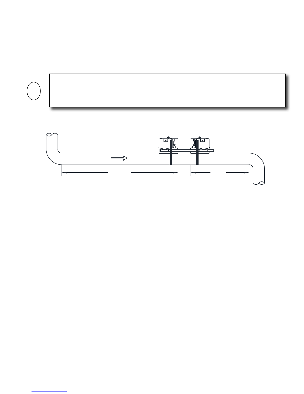
For best results, the transducers must be installed on a straight run of pipe, free of bends, tees,
valves, transitions, insertion probes and obstructions of any kind. For most installations, ten
straight unobstructed pipe diameters upstream and ve diameters downstream of the transducers
is the minimum recommended distance for proper operation. Additional considerations are
outlined below.
IMPORTANT NOTE
In some cases, longer straight runs may be necessary where the transducers are placed downstream
from devices which cause unusual ow prole disruptions or swirl; for example, modulating valves
or two elbows in close proximity and out of plane, etc.
Flow
10 Dia.
• Do not, if possible, install the transducers downstream from a throttling valve, a mixing tank,
the discharge of a positive displacement pump or any other equipment that could possibly
aerate the liquid. The best location will be as free as possible from ow disturbances,
vibration, sources of heat, noise, or radiated energy.
• Avoid mounting the transducers on a section of pipe with any external scale. Remove all
scale, rust, loose paint, etc., from the location prior to mounting the transducers.
• Do not mount the transducers on a surface aberration (pipe seam, etc.).
• Do not mount transducers from different ultrasonic ow meters on the same pipe.
• Do not run the transducer triaxial cables in common bundles with cables from other
instrumentation. You can run these cables through a common conduit ONLY if they originate
at the same ow meter.
• Never mount transducers under water.
• Avoid mounting transducers on the top of a horizontal pipe. The best placement on a
horizontal pipe is either the 10:00 or 2:00 position for 4 or 2 cross mode (Reect), or one
sensor at 9:00 and one sensor at 3:00 for 1 cross mode (Direct).
• Do not mount transducers on the bottom of a horizontal pipe.
• Mounting on a vertical pipe is recommended only if ow is in the upward direction. When
mounting on a vertical pipe owing in a downward direction, make sure there is sufcient
back pressure in the system to maintain a full pipe.
5 Dia.
11451 Belcher Road South, Largo, FL 33773 • USA • Tel +1 (727) 447-6140 • Fax +1 (727) 442-5699 • sales@onicon.com
F-4300 Series Clamp-on Ultrasonic Flow Meter Manual 06/17 - 2056-2 / 37515 Page 11
Page 12
!
i
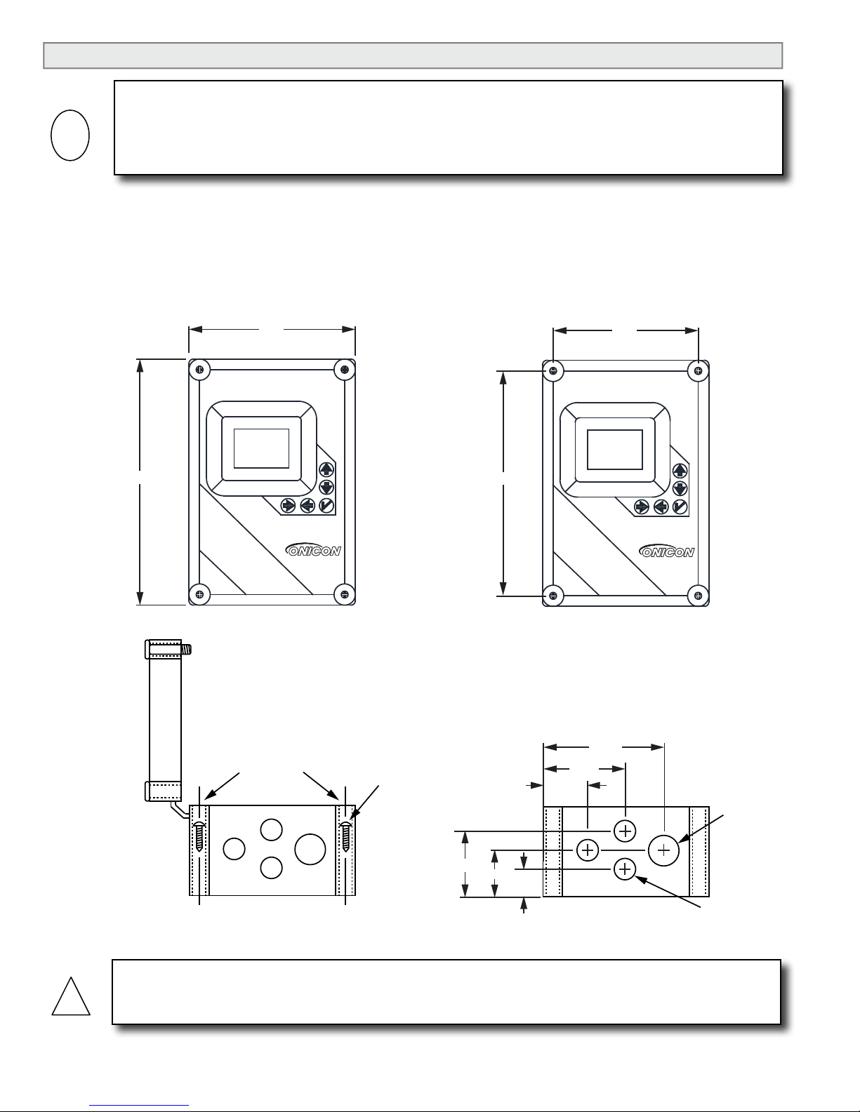
3.3 MECHANICAL INSTALLATION
Transit Time
Ultrasonic Flow Meter
F-4300
10.00”
6.46”
CONDUIT HOLE LOCATIONS
AND DIMENSIONS
Transit Time
Ultrasonic Flow Meter
F-4300
11.00”
7.50”
ENCLOSURE
MOUNTING
HOLES
END VIEW
COVER
MOUNTING SCREWS
INCLUDED WITH
METER
2.74”
2.10”
1.34”
D = 1”
3X D = 0.875”
ENCLOSURE
DIMENSIONS
MOUNTING HOLE
DIMENSIONS
2.00”
3.75”
5.60”
This ONICON F-4300 Ultrasonic Flow Meter is a custom calibrated system. Unless specically
noted in writing by ONICON, ALL COMPONENTS (electronics enclosure and matched transducers)
share associated serial number and must be installed together as a system. Mixing components from
different systems will result in signicant errors in calibration.
IMPORTANT NOTE
3.3.1 Mounting the Enclosure
Find an easily accessible location where electrical connections can be made and meter readings can
be taken from the oor level. Mount the enclosure on a vibration-free surface. Avoid sites such as
the plenum of a fan coil, heat exchanger, or other housings containing motors. Avoid mounting the
enclosure in close proximity to VFD’s, electric motors or other strong sources of electrical interference.
Do not drill additional holes in this enclosure. Doing so may damage the electronic circuitry
contained within and will void all warranties.
11451 Belcher Road South, Largo, FL 33773 • USA • Tel +1 (727) 447-6140 • Fax +1 (727) 442-5699 • sales@onicon.com
F-4300 Series Clamp-on Ultrasonic Flow Meter Manual 06/17 - 2056-2 / 37515 Page 12
CAUTION
Page 13
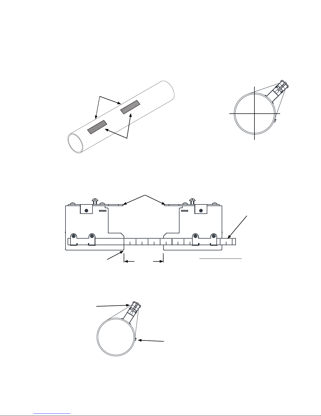
3.3.2 Preparing the Pipe
Once a suitable section of straight pipe has been located, the pipe surface must be prepared. Refer to the
Site Installation Details document provided with the installation hardware to determine the transducer
spacing dimensions. Prepare the pipe surface as shown below. Clean and de-grease two rectangles where
the transducers will be located. Use sand-paper as necessary to remove any grit, corrosion, rust, loose paint
or other contaminants. The cleaned surface should extend at least ½” beyond the length and width of the
transducers.
Always install hardware at the 10:00 or 2:00 position on horizontal pipes. This prevents the ow meter from
being affect by air trapped at the top of the pipe.
Refer to site installation details
document for transducer spacing.
Prepare mounting
locations for transducers.
For horizontal pipes, locate transducers
at the 10:00 or 2:00 position.
3.3.3 4 or 2 Cross Mode (Reect) Mounting Using Frames and Spacer Bar
1. Prepare the pipe surface as described in section 3.3.2.
2. On a at surface, assemble the hardware as shown in the drawing below.
Orient mounting brackets as shown.
Space bar shows distance
between transducers
Reference Position
Separation
Distance
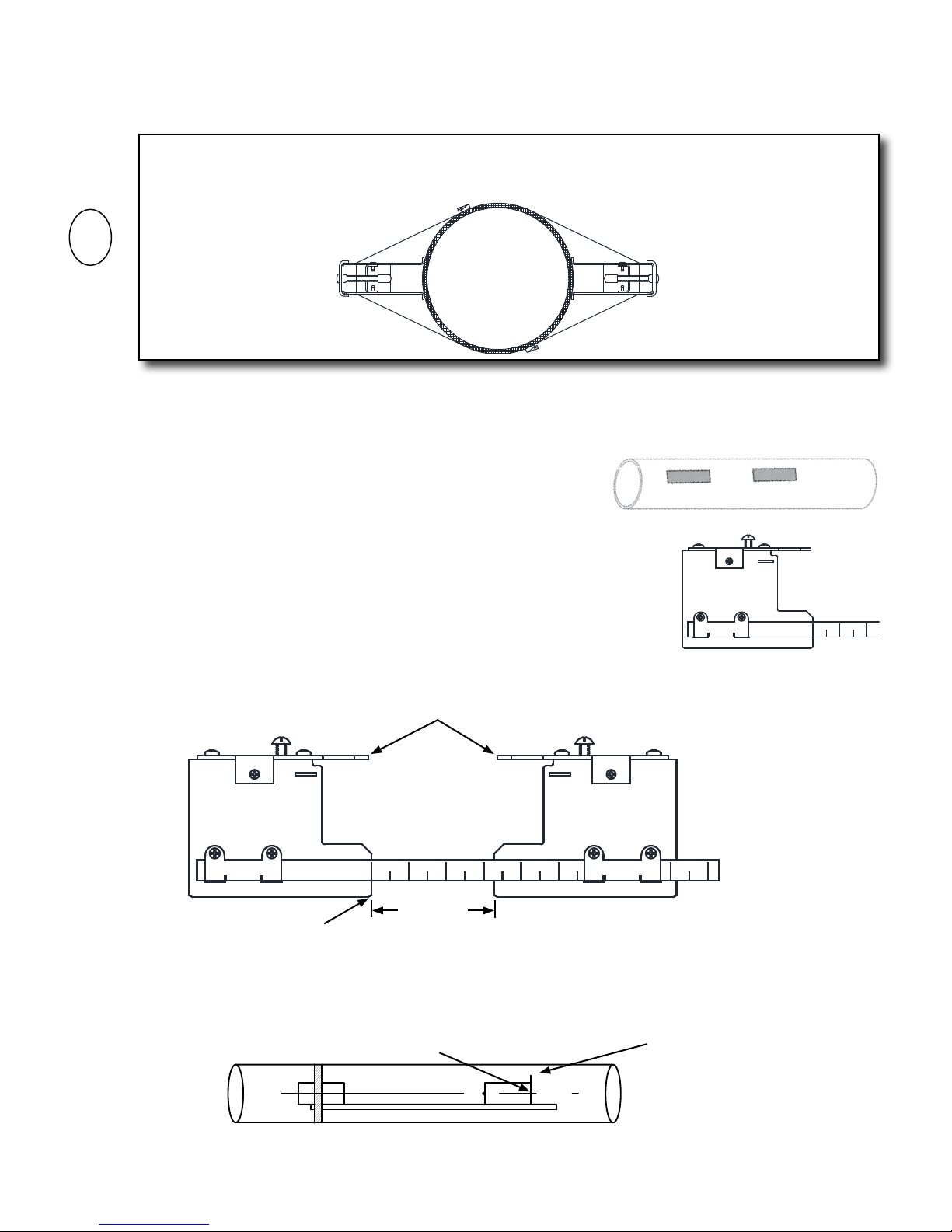
3. Install the mounting straps as shown below. For larger pipes, use multiple straps connected end-to-end
to increase the length of each strap. Leave enough slack in the straps to allow the assembly to be
correctly positioned on the pipe. The location of the routing hole allows for the straps to mount outside
of the pipe insulation, if the pipe is insulated.
Refer to the Site Installation Details document provided with the
installation hardware to determine the correct separation distance.
Routing Holes
4. Move the hardware assembly to its nal position on the pipe. Align the brackets with the prepared surface
for each transducer, ensuring that the entire assembly is properly oriented along the axis of the pipe.
Tighten the assembly rmly on the pipe. Do not over tighten the straps.
11451 Belcher Road South, Largo, FL 33773 • USA • Tel +1 (727) 447-6140 • Fax +1 (727) 442-5699 • sales@onicon.com
F-4300 Series Clamp-on Ultrasonic Flow Meter Manual 06/17 - 2056-2 / 37515 Page 13
Wrap the rst mounting strap around the pipe and through the
holes of the side of the mounting bracket. Make sure to position
it so there is easy access to the adjustment screw. Repeat this
procedure for the second mounting bracket.
Adjustment Screw
Page 14
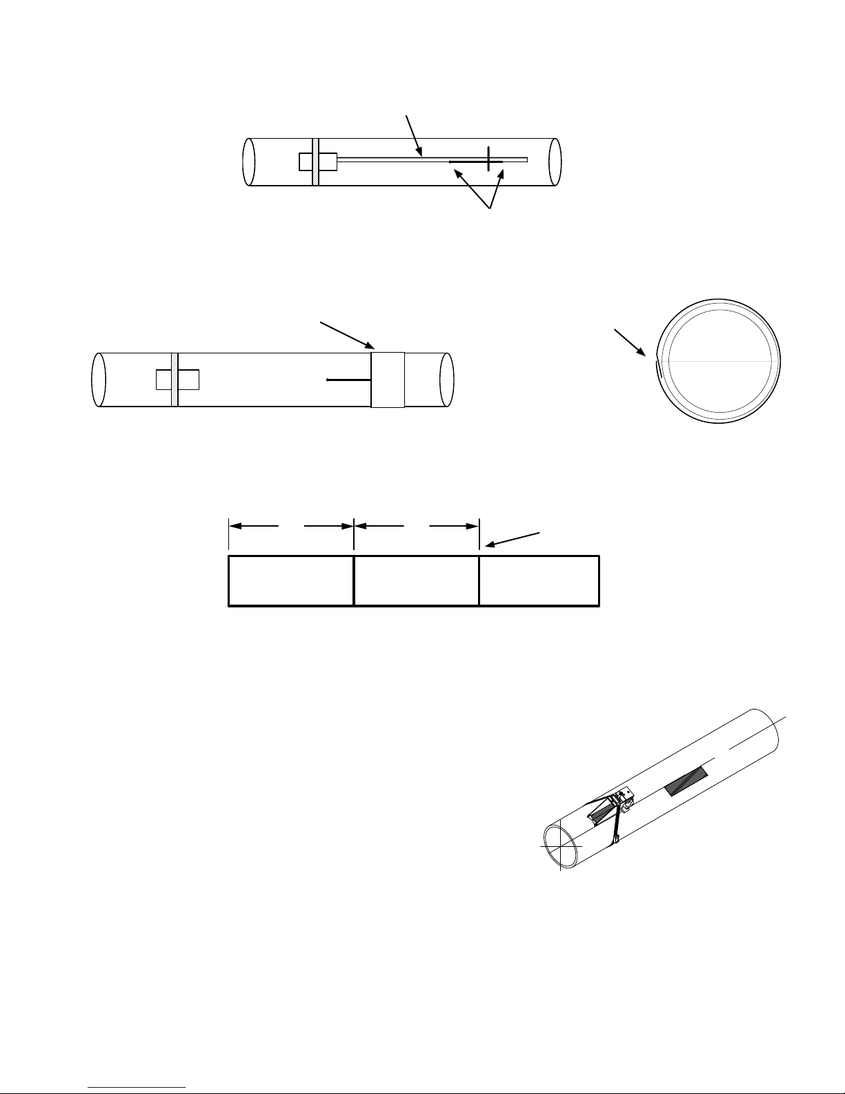
3.3.4 1 Cross Mode (Direct) Mounting Using Brackets and Spacer Bar
i
1. Once the installation site selection process described in section 3.2 is complete, prepare the pipe where
the rst sensor will be mounted.
IMPORTANT NOTE
1 Cross mode mounting requires that transducers be installed on opposite sides of the pipe. For
horizontal pipes, the transducers should be located at the 3 o’clock and 9 o’clock positions.
2. To prepare the pipe, temporarily position a mounting bracket on the pipe where you will be mounting it.
Ensure that the pipe surface is smooth without any raised areas (seams, etc.) With a pencil, marker or chalk,
draw a generous rectangle around the bracket. Clean and de-grease the area within the rectangle. Use the
small sanding block provided with the installation hardware as necessary to remove any grit, corrosion, rust,
loose paint or other contaminants. Be sure to wipe the surface clean
after sanding. The cleaned surface should extend at least ½” beyond
the length and width of the mounting bracket.
3. Attach the spacer bar to one of the mounting brackets at the reference mark on the ruler.
4. Position the mounting bracket and spacer bar in the center of the cleaned
area and secure it in place with a mounting strap as shown below. Make sure
the mounting strap tightening screw is facing up. While tightening the strap,
check to ensure that the bracket remains centered on the pipe. (The bracket is
centered on the pipe when the bottom edges of both stainless side plates on
the bracket are in full contact with the pipe surface.)
5. Attach the second bracket to the spacer bar at the separation distance specied on the site installation
details document provided with the installation hardware.
Orient mounting brackets as shown.
Reference Hole
6. Check to ensure that this bracket is lined up on the center of the pipe. While holding the bracket centered on
the pipe, place a mark (with pencil or chalk) at the center of the bottom of the bracket as shown below. Next,
mark along the edge of the bracket as indicated in the drawing below.
Place mark at center
of bracket roller.
Separation
Distance
Refer to the Site Installation Details document provided with
the installation hardware to determine the correct hole location.
Draw line along edge
of bracket.
11451 Belcher Road South, Largo, FL 33773 • USA • Tel +1 (727) 447-6140 • Fax +1 (727) 442-5699 • sales@onicon.com
F-4300 Series Clamp-on Ultrasonic Flow Meter Manual 06/17 - 2056-2 / 37515 Page 14
Page 15
7. Remove the bracket from the spacer bar and then remove the spacer bar from the bracket that is strapped
to the pipe. Using the spacer bar as a straight edge, draw a line down the center of the pipe intersecting the
mark made at the center of the tapered roller and the line drawn against the edge of the bracket as shown
below.
Spacer bar
Draw line using spacer bar as edge.
8. Wrap a spacing guide (could be a wire, hose clamp) around the pipe so that the left edge is against the
transducer edge mark. Arrange so that one end overlaps the other. Ensure that it is snug around the pipe and
mark along the overlapping edge.
Spacing guide
Draw the guide tightly
around the pipe and mark
at the overlapping edge.
9. Remove the spacing guide and lay it out on a at surface. Either measure the exact distance half-way
between the overlap edge and the mark at the overlap, or fold the guide from the overlap edge to overlap
mark and draw a line at the fold or halfway point.
50%
50%
Overlap edge mark
10. Reinstall the spacing guide; its edge abutting the bracket edge mark on the pipe and the overlapping edge
in line with the line drawn down the center of the pipe. Tape it in this position on the pipe. Take the
second bracket and place it against the edge of the guide with it centered on the half way mark drawn on
the guide.
11. Ensure that the bracket is sitting on a smooth area without any
raised spots (seams, etc.). Mark a generous rectangle around the
bracket with a pencil, marker or chalk. Remove the bracket and the
spacing guide.
12. Clean and de-grease the area within the rectangle. Use the
small sanding block provided with the installation hardware as
necessary to remove any grit, corrosion, rust, loose paint or other
contaminants. The cleaned surface should extend at least ½”
beyond the length and width of the mounting bracket.
13. Replace the spacing guide back in the same position it was in and re-tape it to the pipe.
14. Position the bracket as before against the edge of the guide with the center of the bracket centered on the
half way mark drawn on the guide. Secure it in place with a mounting strap. Make sure the mounting strap
tightening screw is facing toward the bracket so you can hold it in place while tightening the screw. While
tightening the strap, check to ensure that the bracket remains centered on the pipe. (The bracket is centered
on the pipe when the bottom edges of both stainless steel side plates on the bracket are in full contact with
the pipe surface.)
11451 Belcher Road South, Largo, FL 33773 • USA • Tel +1 (727) 447-6140 • Fax +1 (727) 442-5699 • sales@onicon.com
F-4300 Series Clamp-on Ultrasonic Flow Meter Manual 06/17 - 2056-2 / 37515 Page 15
Page 16

3.3.5 Installing Transducers In Bracket and Spacer Bar Hardware
1. Apply the coupling to the transducer as show below. A packet of Super Lube was supplied with
the transducers. Contact ONICON if you need more compound.
Apply a continuous lengthwise ¼” wide bead of coupling
compound down the center of the transducer.
2. Slide the transducer into the mounting bracket. Do not allow the bottom of the transducer to make
contact with the pipe until it butts against the mounting bracket. The clamping bracket can be
retracted such that the transducer cam be directly over the correct position before making contact
with the pipe. Push down rmly on the transducer to mate with pipe.
When installing the transducer, do not allow
the bottom face to touch the pipe surface
until it is fully inserted to the bracket.
3. Tighten the transducer clamping screw to hold the transducer rmly in place. Do not over
tighten the screw. If you are not routing exible conduit all the way to the mounting bracket,
you can remove the conduit adapters to make installation easier.
Conduit Adapter
Transducer Clamping Screw
4. Connect transducer cable female BNC to transducer male BNC. Slide
the protective rubber boot over the transducer’s BNC connector. In
environments where condensation may occur (Chilled water systems),
apply a generous amount of Super Lube dielectric grease inside the
boot before sliding it over the BNC connector.
5. Repeat procedure for the second transducer.
11451 Belcher Road South, Largo, FL 33773 • USA • Tel +1 (727) 447-6140 • Fax +1 (727) 442-5699 • sales@onicon.com
F-4300 Series Clamp-on Ultrasonic Flow Meter Manual 06/17 - 2056-2 / 37515 Page 16
Page 17

SENSOR MOUNTING/COUPLING RECOMMENDATIONS
BAD
GOOD
Sensor Mounting / Coupling Recommendations
GOOD
BAD GOOD
Air at the top of the
pipe well disrupt the
signal
Solids at the bottom
of the pipe will
disrupt the signal
Too little grease
Transducer
face should be
perpendicular to pipe
surface.
Ensure transducers
are parallel with pipe
axis and ush to the
pipe surface
11451 Belcher Road South, Largo, FL 33773 • USA • Tel +1 (727) 447-6140 • Fax +1 (727) 442-5699 • sales@onicon.com
F-4300 Series Clamp-on Ultrasonic Flow Meter Manual 06/17 - 2056-2 / 37515 Page 17
Page 18

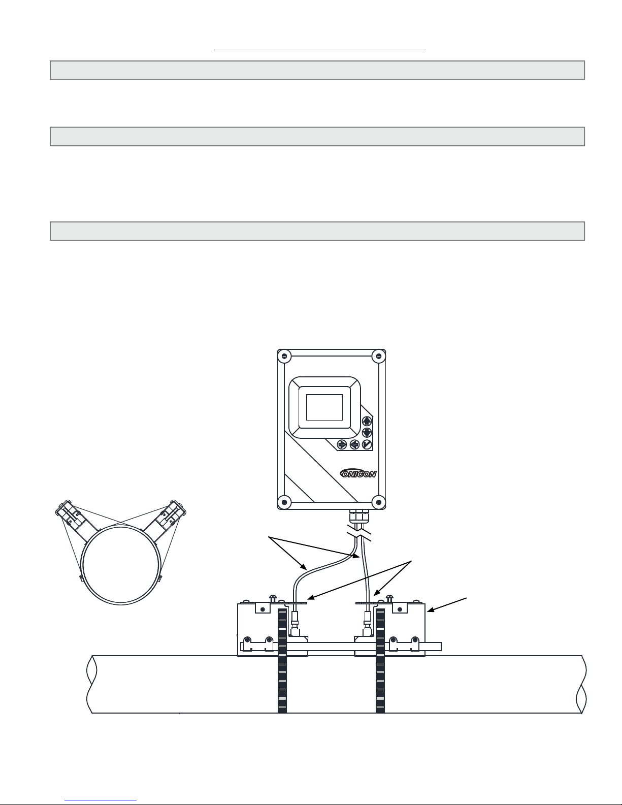
3.4 CONNECTING THE TRANSDUCER SIGNAL CABLES
!
i
i
ONICON F-4300 transducer cables are special purpose triaxial cables. Care must be taken when installing
the cables to ensure that electrical noise will not affect the performance of the meter. The cables must NOT
be bundled or run in conduit with any other signal or power cables. The maximum allowable cable length
is 100 ft.
To install the cables, rst locate and install the wall-mount electronics enclosure and the transducers.
F-4300
Transit Time
Ultrasonic Flow Meter
F-4300
Transit Time
Ultrasonic Flow Meter
The transducer cables are provided with BNC connectors already installed at one end of the cable. Install
this end of each cable at the transducers.
IMPORTANT NOTE
If using, conduit, route cables from transducer through conduit to electronics enclosure.
WARNING
For proper operation, cables must not be bundled or run in conduit with any other signal or power
cables.
At the enclosure, the transducer cable should be landed as follows:
IMPORTANT NOTE
The upstream terminal should route to the upstream transducer. Same for
the downstream. If cables are discovered to be backwards after installation,
simply reverse the cable installation inside the enclosure.
11451 Belcher Road South, Largo, FL 33773 • USA • Tel +1 (727) 447-6140 • Fax +1 (727) 442-5699 • sales@onicon.com
F-4300 Series Clamp-on Ultrasonic Flow Meter Manual 06/17 - 2056-2 / 37515 Page 18
Page 19

!
3.5 ELECTRICAL INSTALLATION
!
!
!
All user supplied conduit ttings, junction boxes, etc. must be installed in compliance with
federal, state and local building codes.
3.5.1 Input Power Options
The F-4300 can be ordered with two different input voltage options. The input power
options are:
18 - 30 VDC/VAC, 10 VA maximum
100 - 240 VAC 50/60 Hz, 10 VA maximum
WARNING
Conduit openings in the F-4300 enclosure must be closed with UL listed ttings applicable to NEMA
4 enclosures.
WARNING
The protective earth connection must be made as shown in Section 3.5.2. Failure to do so will result
in an increased risk of injury.
WARNING
All mains voltage connections must be made through the pre-drilled conduit/strain relief opening
located at the bottom of the enclosure. Failure to do so will result in an increased risk of injury.
CAUTION
This product must be connected to earth ground for proper operation. Failure to do so may result in
erratic operation.
11451 Belcher Road South, Largo, FL 33773 • USA • Tel +1 (727) 447-6140 • Fax +1 (727) 442-5699 • sales@onicon.com
F-4300 Series Clamp-on Ultrasonic Flow Meter Manual 06/17 - 2056-2 / 37515 Page 19
Page 20

3.5.2 Electrical Connections
!
3.5.2.1 Connections for Meters Powered by 100-240 VAC
WARNING
Turn off mains power at the source prior to making power connections to the F-4300. Contact with
exposed live wiring may result in electric shock, burns and/or serious injury.
11451 Belcher Road South, Largo, FL 33773 • USA • Tel +1 (727) 447-6140 • Fax +1 (727) 442-5699 • sales@onicon.com
F-4300 Series Clamp-on Ultrasonic Flow Meter Manual 06/17 - 2056-2 / 37515 Page 20
Page 21

3.5.2.1 Connections for Meters Powered by 10-30 VAC/VDC
!
WARNING
Turn off mains power at the source prior to making power connections to the F-4300. Contact with
exposed live wiring may result in electric shock, burns and/or serious injury.
11451 Belcher Road South, Largo, FL 33773 • USA • Tel +1 (727) 447-6140 • Fax +1 (727) 442-5699 • sales@onicon.com
F-4300 Series Clamp-on Ultrasonic Flow Meter Manual 06/17 - 2056-2 / 37515 Page 21
Page 22

SECTION 4.0: START-UP
ONICON F-4300 ow meters are normally shipped with the intended installation parameters preprogrammed into the memory of the meter. This pre-programmed site is based on installation data
provided to ONICON when the meter was ordered. The information programmed into the meter is
also provided in a document that accompanies the installation hardware. It is titled, “Site Installation
Details”.
If the information contained in the Site Installation Details document matches that specic installation
location, then after the transducers are installed, connected, and powered on, the meter should
establish a ow reading on its own. If there is any discrepancy between programmed parameters and
actual site conditions, then the programming for the site must be edited before it is used. This manual
contains information on programming the meter in the eld, but if you require any assistance, please
contact ONICON for assistance.
4.1 NAVIGATING THE RUN MODE & PROGRAMMING PAGES
The diagram on the next page shows the F-4300 menu system. Arrows show the four directions to
navigate between menu boxes. Pressing a corresponding keypad arrow will move to the next item
in the direction shown. Move the cursor (highlighted) under numerals with the
and keys, and increase or decrease numerals with the and keys.
Programming values are stored permanently after pressing the .
11451 Belcher Road South, Largo, FL 33773 • USA • Tel +1 (727) 447-6140 • Fax +1 (727) 442-5699 • sales@onicon.com
F-4300 Series Clamp-on Ultrasonic Flow Meter Manual 06/17 - 2056-2 / 37515 Page 22
Run Mode View
Page 23

--Password----------
Password 0000
--Message-----------
--24 hr log----------
--Status------------
--Menu Selections----
--Units/Mode--------
--Data Logging-------
--Simulation--------
--Relay Parameters--
--Configuration-----
--Special Functions-
--Calibration-------
USG/m
Tot 20130.8 USG
Relays 1 2 3 4 5 6
0.000
----Setup------
Signal
Strength
100
%
--Communication
Protocol
DevID
MAC Address
BPS
BACnet
57017
017
38400
Mode
Volume
Velocity
Flow
Temperature
Flow
USG
ft/s
USG/m
F
Sensor Select
Fluid
Fluid Temp
Pipe OD
Pipe Wall
Pipe
Lining
Crossings
Zero Tare
Sens Space
Velocity
SE16B
Water
21.6C
4.5000in
0.2500in
PVC
None
2
No
2.59in
0.00ft/s
20mA
4mA at
Min Flow
Damping
Cal Constant
2500.0 USG/m
0.000 USG/m
2.262 USG/m
5%
1.000
Relay
Function
Mode
On
Off
1
Flow
Pump
1000 USG
0.000 USG
Log Site ID
Mode
Set Date
Set Time
Interval
Log
0
Flow
Jun 22/2012
11:27:40
10sec
Logging
Language
Analog Out
Backlight
Reset Totalizer
Negative Totals
Restore Defaults
New Password
English
4-20mA
High
NO
NO
NO
0000
Test
Flow
4-20mA
Relays Flow
Actual
250USG/m
5.60mA
1 2 3 4 5 6
Utility
Transit Time
Logger
Relays
Analog Out
1.25.00
03 1.
1. T
2
124
Set up
Calibration
Relay Parameters
Communication
Data Logging
Communication
Special Functions
Simulation
Configuration
Velocity
Signal Strength
Relays
0.00 ft/s
100%
1 2 3 4 5 6
Data log
Log Use
Sensor
Logging
0%
Good
Date Feb. 12/20
Total
Average
Maximum
Max Time
Minimum
Min Time
10
50138 USG
34.82 USG/m
52.20 USG/m
11:08:00
0.000 USG/m
9:15:00
4.2 RUN MODE & PROGRAMMING PAGE LAYOUT
11451 Belcher Road South, Largo, FL 33773 • USA • Tel +1 (727) 447-6140 • Fax +1 (727) 442-5699 • sales@onicon.com
F-4300 Series Clamp-on Ultrasonic Flow Meter Manual 06/17 - 2056-2 / 37515 Page 23
Page 24

4.3 RUN MODE ICONS
ICONS
Message waiting. Press .
Data logging off.
Data logging on.
USB le download.
File download complete.
Download Error.
4.4 RUN MODE PAGES
USG/ m
0.000
Tot 20130.8 USG
Relays 1 2 3 4 5 6
Ultrasonic Echo OK.
No Echo, Empty Pipe.
No Sensors Attached / Wrong Settings
Main Display Page - The MAIN display shows the ow
rate and totalizer in the units selected via the programming
menu. You will see velocity instead of ow rate if you
selected the velocity operating mode in the programming
menu.
The bottom of the MAIN display shows the status of the
pulse outputs. If any of the meter’s pulse outputs are
congured for volume totalization, the background of the
specic pulse output programmed for this totalization will
turn black, and then back to white after the pulse duration.
If set for ow alarm, the background of the specic pulse
output set for this alarm will turn black when latched on,
and back to white when latched off.
11451 Belcher Road South, Largo, FL 33773 • USA • Tel +1 (727) 447-6140 • Fax +1 (727) 442-5699 • sales@onicon.com
F-4300 Series Clamp-on Ultrasonic Flow Meter Manual 06/17 - 2056-2 / 37515 Page 24
The top-left corner of the MAIN display shows the status
icons. Refer to the previous page for their descriptions.
Page 25

Message Display Page - Pressing from the MAIN
display will navigate you to the MESSAGE page. On this
page you can nd the status of the logger, % log used, sensor
status, and temperatures measured by both the upstream and
downstream transducers.
Status Display Page - Pressing
from the MAIN display
will navigate you to the STATUS page. On this page you
can see the ow velocity in units programmed in the meter,
signal strength, and relay status again.
Signal strength is an important diagnostic tool. The value
can be anywhere between 0-100%. 100% indicates that the
meter is successfully transmitting between the upstream and
downstream transducers.
If you have no ow, erratic ow, or inaccurate ow, this
signal strength number should be noted. You will need to
check transducer installation, pipe type and dimensions, and
meter programming to resolve these potential issues.
24 Hour Log Display Page - Pressing
from the MAIN
display will navigate you to the 24 HOUR LOG display. By
pressing the down arrow, you can view total ow, average
ow, maximum ow, max ow time, minimum ow, and
minimum ow time for any day after the meter has been
deployed. Up to 365 days are stored, and after that date, the
oldest data is removed to make room for the newest.
Password Display Page - Pressing the
from the MAIN
display navigates you to the password entry page if the
password has been changed from the default of 0000. This
page comes directly before the programming menu, and
is meant to allow you the ability to prevent malicious
programming changes after deployment. The password can
be changed at any time by navigating into the programming
menu and changing it. See section 4.5 for instructions on
changing this value. If the password has been changed from
the default, use the directional buttons to change the digit
values, then the
to accept the password and move into
the programming menu.
11451 Belcher Road South, Largo, FL 33773 • USA • Tel +1 (727) 447-6140 • Fax +1 (727) 442-5699 • sales@onicon.com
F-4300 Series Clamp-on Ultrasonic Flow Meter Manual 06/17 - 2056-2 / 37515 Page 25
Page 26

4.5 PROGRAMMING MENU PAGES
--Units/Mode--------
Mode
Volume
Velocity
Flow
Temperature
Flow
USG
ft/s
USG/m
F
Any changes made in these menus are automatically saved, and take effect immediately. Your
meter should have arrived pre-programmed by ONICON, so please use caution when changing any
parameters which affect the setup the meter, such as the pipe material or pipe size.
For list selection options, press the
selection. Press
and
to navigate to different values, and then or to change the value selected. Press
to accept the change. For numeric entry options, press the to enter it,
at any option to select it, and the or to change the
to accept the change.
Units/Mode Menu Page
The Units/Mode page allows the user to dene whether the meter
is congured to display velocity or ow rate, as well as dene the
engineering units seen on the MAIN display and programming menus.
Mode – Select between “Flow” or “Velocity” for the MAIN display
reading.
Options: Flow, Velocity
Volume – Select units for volume domain.
Options: USG (US gallons), ft3 (cubic feet), L (liters), m3 (cubic meters)
Velocity – Select units for ow velocity and uid sonic velocity.
Options: ft/s (feet per second), m/s (meters per second)
Flow – Select units for volumetric ow rate.
Options: USG/m (gallons per minute), m3/h (cubic meters per hour), L/s (Liters per second),
ft3/m (cubic feet per minute)
Temperature – Select units for temperature domain.
Options: F (Degrees Fahrenheit), C (Degrees Celsius)
Setup Menu Page
The Setup page allows the user to dene the type of transducer used, and to dene process
conditions like pipe material & size, and uid type & temperature. After these settings are dened,
the spacing distance will be displayed on this page, and once the transducers are installed the
meter will be ready to work.
All of these settings are pre-congured by ONICON before shipment. These settings should only
be adjusted if the process conditions provided to ONICON at time of order were incorrect, or
different transducers were supplied for eld installation.
Sensor Select – SE16B is the only option available at this time.
Angle – Select the angle of the transducer. Contact ONICON for assistance dening what angle
sensors you have.
Fluid – Select between Water or Other. When Water is selected, the speed of sound of the uid is
determined based on the temperature entered later in this Setup menu.
11451 Belcher Road South, Largo, FL 33773 • USA • Tel +1 (727) 447-6140 • Fax +1 (727) 442-5699 • sales@onicon.com
F-4300 Series Clamp-on Ultrasonic Flow Meter Manual 06/17 - 2056-2 / 37515 Page 26
Page 27

Vel@25C – Only appears if “Other” was selected at the Fluid option. Enter the speed of sound of
the uid at 25°C (77°F). Units are dened by what was selected in the Units/Mode menu.
dV/C – Only appears if “Other” was selected at the Fluid option. This denes how much the
speed of sound varies per degree C. This should be left at 0 unless the speed of sound change of
the uid is linear with respect to temperature.
Temp Mode – Should be left at “Fixed”
Temp – Temperature of the uid. If “Water” was selected at
Fluid, enter the water temperature. If “Other” was selected
at Fluid, enter 25.0C or 77.0F for the uid temperature,
depending on units of measurement selected.
Pipe – Select the pipe material.
Options: Carbon Steel, Brass, Aluminum, Acrylic, ABS, Other,
Stainless 430, Stainless 410, Stainless 347, Stainless 316, Stainless 304, Stainless 303, Stainless
302, Mild Steel, PVC, Poly HD, Poly LD, Nylon, Iron, FRP, Ductile Iron, CPVC, Copper, Cast Iron.
Vel – If “Other” pipe material was chosen, enter the sonic velocity of the pipe material here.
Units of measurement are dened in the Setup menu.
OD – Enter the pipe’s outside diameter in units dened in the Setup menu. Charts with
standard pipe sizes based on schedule are provided in the appendix of this manual.
Wall – Enter the pipe’s wall thickness in units dened in the Setup menu. Charts with
standard pipe sizes based on schedule are provided in the appendix of this manual.
Lining – Select whether or not the pipe the meter is being mounted to has a liner.
Options: None, Tar Epoxy, Rubber, Mortar, Asb Cement, Other
Thick - Enter the liner thickness in units dened in the Setup menu. Only appears if Lining is
not “None”
Crossings – Denes the number of times the ultrasonic signal
crosses the inside of the pipe. The rst choice used should be 2 or 4
crosses.
1 crossing is a “Z” or “Direct” mode, 2 crossings is a “V” or
“Reect” mode, and 4 crossings is a “W” or “Double Reect” mode.
1 crossing will provide the largest signal strength but more diligence
is required to mount the transducers properly.
2 crossings provide the easiest means to mount the transducers,
averages some of the ow distortions in the pipe, but attenuates
the signal more than 1 cross. This is the default and ONICON
recommended conguration.
4 crossings provide even more averaging than 2 crosses. 4 crosses
will not be an option unless the transducers overlap in a 2 cross
setup, which is dependent on pipe settings and uid sonic velocity.
Zero Tare – Used to suppress readings or uctuations at zero ow.
Do not enable this function unless ow in the pipe has been valved to 0, and the pipe is full.
Sens Space – This function is not editable. This value will automatically calculate after the
sensor type, angle, uid type and temperature, pipe material and size, and number of crossings
is dened. This distance is dened as the measurement between the inside of both transducers.
Because the meter comes pre-programmed from ONICON, this number is already dened for you
on the “Site Installation Details” sheet. However, if any of the factors listed above is changed in
the eld, you will need to change the transducer spacing to the new number provided here.
11451 Belcher Road South, Largo, FL 33773 • USA • Tel +1 (727) 447-6140 • Fax +1 (727) 442-5699 • sales@onicon.com
F-4300 Series Clamp-on Ultrasonic Flow Meter Manual 06/17 - 2056-2 / 37515 Page 27
Page 28

Velocity – After mounting the transducers and connecting the transducer cable, you will be able to
see the ow velocity in real-time once ow is established.
Signal Strength – After mounting the transducers and connecting the transducer cable, you will
be able to see the signal strength in real-time. The pipe must be full of water to get a valid signal
strength reading.
Calibration Menu Page
The calibration menu denes the behavior of the ow measurement
and its related outputs.
Mode – Shows the Mode which was selected in the Units/Mode
menu. Could be “Flow” or “Velocity.”
20 mA at or 5V at – Enter the desired ow rate to be equal to 20
mA or 5V.
4 mA at or 0V at – Enter the desired ow rate to be equal to 4 mA
or 0V. Typically, 0 ow/velocity, but could be a negative value if
you wanted the 4-20 mA/0-5V output to represent more than one direction.
Min Flow – Value which if the measured ow rate falls below, the meter will force the reading and
outputs to 0. Units match those congured in the Units/Mode menu. The default and recommended
value is the volumetric ow rate equivalent to 0.1 ft/sec in your pipe size.
Damping – The damping value stabilizes the ow rate on the display and analog output. For
applications with poor straight run, use a higher dampening value to steady the ow reading. Lower
dampening values should be used in applications where you want a faster response from the meter.
The default dampening value is 20%.
Cal Constant – Calibration constant dened during calibration. This value shouldn’t be changed
unless ONICON support has requested to do so.
Relay Parameters Menu Page
The relay parameters page is where changes can be made to the
pulse outputs available with the F-4300
Relay – Denes which pulse output you are making changes to,
either 1 or 2.
Function – Denes the behavior of the pulse output selected at the
Relay option. Choices:
On – Pulse is always engaged
Off – Pulse is always disengaged
Pulse – Scaled pulse. Dene how many gallons must be
measured before a pulse occurs.
Pulse duration = 50 ms; max Hz = 10
11451 Belcher Road South, Largo, FL 33773 • USA • Tel +1 (727) 447-6140 • Fax +1 (727) 442-5699 • sales@onicon.com
F-4300 Series Clamp-on Ultrasonic Flow Meter Manual 06/17 - 2056-2 / 37515 Page 28
Page 29

Data Logging Menu Page
i
--Units/Mode--------
--Data Logging-------
--Relay Parameters--
--Calibration-------
---- Setup------
Signal
Strength
100
%
--Communication
Protocol
DevID
MAC Address
BPS
BACnet
57017
017
38400
Mode
Volume
Velocity
Flow
Temperature
Flow
USG
ft/s
USG/m
F
Sensor Select
Fluid
Fluid Temp
Pipe OD
Pipe Wall
Pipe
Lining
Crossings
Zero Tare
Sens Space
Velocity
SE16B
Water
21.6C
4.5000in
0.2500in
PVC
None
2
No
2.59in
0.00ft/s
20mA
4mA at
Min Flow
Damping
Cal Constant
2500.0 USG/m
0.000 USG/m
2.262 USG/m
5%
1.000
Relay
Function
Mode
On
Off
1
Flow
Pump
1000 USG
0.000 USG
Log Site ID
Mode
Set Date
Set Time
Interval
Log
0
Flow
Jun 22/2012
11:27:40
10sec
Logging
--Units/Mode--------
--Data Logging-------
--Relay Parameters--
--Calibration-------
---- Setup------
Signal
Strength
100
%
Mode
Volume
Velocity
Flow
Temperature
Flow
USG
ft/s
USG/m
F
Sensor Select
Fluid
Fluid Temp
Pipe OD
Pipe Wall
Pipe
Lining
Crossings
Zero Tare
Sens Space
Velocity
SE16B
Water
21.6C
4.5000in
0.2500in
PVC
None
2
No
2.59in
0.00ft/s
20mA
4mA at
Min Flow
Damping
Cal Constant
2500.0 USG/m
0.000 USG/m
2.262 USG/m
5%
1.000
Relay
Function
Mode
On
Off
1
Flow
Pump
1000 USG
0.000 USG
Log Site ID
Mode
Set Date
Set Time
Interval
Log
0
Flow
Jun 22/2012
11:27:40
10sec
Logging
The Data Logging page allows conguration of the data logger. Options include what is being logged,
how often it is being logged, and the date settings.
Log Site ID – Provide a number to the log site you’re creating. Can be any number between 00-99.
Mode – Dene what is being logged. Options: Flow, Velocity.
File Format – Dene how you will want the data presented when downloaded. Choose .LG2 when
you will be looking at the log data with the ONICON Logger Utility software. Choose .CSV when you
will be loading the data directly into an Excel spreadsheet for manipulation and graphing.
Date – Congure today’s date. Format: Month Day/Year.
Time – Congure the time. Format: hh:mm:ss. Range: 00:00:00-23:59:59.
Interval – Dene how often the unit selected under Mode will log.
Options: 10 sec, 30 sec, 1 min, 2 min, 5 min, 10 min, 15 min, 30 min,
and 60 min.
At the fastest interval, 10 sec, the logger will last 8.5 years before it is
full. However, if you are curious about the % log used, it is available in
the Messages Menu accessible from the Run Screen by pressing the
Flow – Pulse output functions as a ow alarm. You will need to dene when the alarm comes
ON, and when the alarm will turn OFF again.
Examples:
High Flow Alarm: ON = 300 GPM, OFF = 250 GPM
Flow goes above 300 GPM and the pulse output latches ON. It will not turn OFF until ow
goes below 250 GPM.
Direction Switch: ON = +0.1 GPM, OFF = -0.1 GPM
Any ow above 0.1 GPM will cause the pulse to turn ON, and it will turn off should ow reverse.
The logger must be congured in a specic order in order to function correctly:
1. Set the Log Site ID, Mode, File Format, Date, Time, and Interval to the desired option.
2. Under Data Log, select “Delete”
3. Under Data Log, select “Start”
Deploying the logger in any other order will compromise the settings you’ve chosen.
IMPORTANT NOTE
.
11451 Belcher Road South, Largo, FL 33773 • USA • Tel +1 (727) 447-6140 • Fax +1 (727) 442-5699 • sales@onicon.com
F-4300 Series Clamp-on Ultrasonic Flow Meter Manual 06/17 - 2056-2 / 37515 Page 29
Although the logger storage capability is quite extensive, ONICON recommends not using an
interval more resolute than required, as downloading a large log le could present data transfer
problems and corrupted data.
Communications Menu Page
The communications menu allows provides the means to select the
serial output of the meter, and the addressing and communication
speed.
Protocol – Select the protocol for the serial communications. Options:
BACnet, OFF
DevID – Only available if BACnet was the selected Protocol. This is the Device ID which must be
unique for the device across the whole BACnet network. Range: 0-4,194,302.
Page 30

MAC Address – Only available if BACnet was the selected Protocol. This is the RS485 bus address
for the BACnet MS/TP communications. Range: 0-127 for master devices, 128-254 for slave devices.
BPS – BAUD Rate, or bits per second. Denes the speed of communication on the BUS. Must be the
same for all devices on the BUS. Options: 9600, 19200, 38400, 76800.
Special Functions Menu Page
Language – Select the language for the menus and display. Options: English, French, Spanish.
Analog Out – Denes the analog output type. Options: 4-20 mA, 0-5V.
Backlight – Raise or lower the brightness of the display backlight. Options: Off, High, Med, Low, Key Hi/
Lo (Brightness goes to High after a keypress, then Low after 1 minute of no button presses), Key High,
Key Med, and Key Low (Brightness goes to specied value after keypress, then OFF after 1 minute).
Reset Totalizer – Select YES to reset totalizer. YES will ash two times after pressing
to
indicate the action was accepted.
Neg. Totals – Selecting NO will cause the totalizer to ignore ow
rates in the negative direction. Only positive ows will accumulate
the totalizer. Selecting YES will cause negative ows to deduct from
the totalizer. Totalizer values can achieve a negative value if negative
totals are greater than positive totals.
Restore Defaults – Selecting YES will cause all of the programming settings to revert to the factory default. These defaults are
different than the programming ONICON performed at the factory
before the meter was shipped.
New Password – This function allows a new password to be set. This password protects the
programming menu access from the Main Display. The default value is 0000. Range: 0000-9999. Do not
lose the password if changed, in case you need to return to the programming menu at a later date.
Simulation Menu Page
The simulation menu page is used to generate ow rates independent of the actual measurement in
the system, in order to test output signals.
Any simulated ow rate is only active while the Simulation Menu is open. Once the menu is exited,
the ow rate and output signal behavior will return to that actually measured by the meter.
Test – This function denes how the simulation mode will be tested. Options: Actual, Maximum,
Minimum.
11451 Belcher Road South, Largo, FL 33773 • USA • Tel +1 (727) 447-6140 • Fax +1 (727) 442-5699 • sales@onicon.com
F-4300 Series Clamp-on Ultrasonic Flow Meter Manual 06/17 - 2056-2 / 37515 Page 30
Page 31

When Actual is selected, any ow rate which is currently present will be displayed on the screen,
and the outputs associated with that ow rate is also displayed. Alternatively, you can move the
cursor to the Flow option, press
set a ow rate manually. After
to enter the option, and then
is pressed, the analog output
and pulse outputs will be driven by the set ow rate.
When Maximum is selected, the ow rate will be driven to the 20
mA/5V value congured in the Calibration Menu Page.
When Minimum is selected, the ow rate will be driven to the 4 mA/0V value congured in the
Calibration Menu Page.
Conguration Menu Page
The conguration menu page stores the serial number and electronics information for the F-4300.
All of the values in this menu are read-only.
Serial # - Serial number of the F-4300. This value is also present on the outside of the enclosure,
and inside the door.
Utility – Revision of the utility card. The utility card is the vertical card on the left hand side of the
chassis. It connects to the LCD display, and has the analog and pulse outputs on it.
TransitTime – Revision of the transit time card. The Transit time card is the topmost horizontal
card, with the two connectors attached to the Triax cable.
CommBoard – Revision of the communications card.
Relays – Lists the number of pulse outputs present on the meter.
This should always be 2.
Analog Out – Lists the number of analog outputs present on the
meter. This should always be 1.
11451 Belcher Road South, Largo, FL 33773 • USA • Tel +1 (727) 447-6140 • Fax +1 (727) 442-5699 • sales@onicon.com
F-4300 Series Clamp-on Ultrasonic Flow Meter Manual 06/17 - 2056-2 / 37515 Page 31
Page 32

SECTION 5.0: BACnet® MS/TP
BACnet® MS/TP, serial interface connections are connected at the RS485 card’s terminal block.
Transceiver: 2-wire, half-duplex
BACnet
®
address (MAC address) range: 1 - 255 (Default: 017)
Device Instance: 0 - 4,194,303 (Default: 57017)
Baud rate: 9600, 19200, 38400 or 76800
(Default: 38400)
Termination: 120 ohms or none (Default: none)
Jumper JP1 position 1 + 2 = OFF.
Jumper JP1 position 2 + 3 = ON
Biasing: None
Flow control: None
®
5.1 BACnet
OBJECT TYPES
BACnet® Object Type and Number of Objects Implemented
Device: 1
Analog Input: 3
Analog Value: 5
Binary Value: 3
Multistate Object: 2
RS485 Output Card
5.2 PROTOCOL IMPLEMENTATION STATEMENT
BACnet® Protocol Revision: 10
Device Prole (Annex L): BACnet® Application Specic Controller (B-ASC)
MS/TP master (Clause 9), baud rate(s): 9600, 19200, 38400 & 76800
Device Address Binding: No
BBMD support registration by Foreign Devices: No
Character Set Supported: ANSI X3.4
BACnet® Interoperability Building Blocks Supported (Annex K):
Data Sharing-ReadProperty-B (DS-RP-B)
Data Sharing - ReadProperty Multiple - B (DS-RPM-B)
Data Sharing-WriteProperty-B (DS-WP-B)
Data Sharing - WriteProperty Multiple - B (DS-WPM-B)
Device Management-Dynamic Device Binding - B (DM-DDB-B)
Device Management-Dynamic Object Binding - B (DM-DOB-B)
Device Management-DeviceCommunicationControl-B (DM-DCC-B)
Device Management-Time Synchronization - B (DM-TS-B)
Device Management - UTC Time Synchronization – B (DM-UTC-B)
Standard Object Types Supported:
Device Object Binary Value Object
Analog Input Object Multi-State Value
Analog Value Object
11451 Belcher Road South, Largo, FL 33773 • USA • Tel +1 (727) 447-6140 • Fax +1 (727) 442-5699 • sales@onicon.com
F-4300 Series Clamp-on Ultrasonic Flow Meter Manual 06/17 - 2056-2 / 37515 Page 32
Page 33

5.3 DEVICE OBJECT
Property Default Value Read-only or
Comment
Writable
Object Identier 57017 Writable 0-4,194,303
Object Name ONICON F-4300-XXXXXX Read-only XXXX= Serial
No.
Object Type Device Read-only
System Status Operational Read-only
Vendor Name ONICON Inc. Read-only
Model Name F-4300 Read-only
Firmware Rev. 000.006.000 Read-only
Location Customer Location Writable 32 char. Max
Description Customer Description Writable 32 char. Max
Protocol Version 1 Read-only
Protocol Revision 10 Read-only
Services Supported Read property, Read property multiple,
Read-only
Write property, Write property
multiple, Read range, Who-has, I have,
Who-is, I-am, Device communications
control, Time synchronization, UTC
time synchronization
Object Types Supported Analog input, Analog value, Binary
Read-only
input, Device, Multi-state value
Object List (Device, 57017), (analog input, 1-3),
Read-only
(analog value, 1-5), (binary value, 1-3),
(multi state value, 1-2)
Max ADPU Length 480 Read-only
Segmentation Supported NO-SEGMENTATION (2) Read-only
Local Time Device current time Read-only
Local Date Device current date Read-only
UTC Offset -300 Writable
Daylight Savings Status False Writable
APDU Timeout 6000 Read-only
# of APDU Retries 3 Writable
Max Master 127 Read-only
Device Address Binding Read-only
Database Revision 1 Read-only
11451 Belcher Road South, Largo, FL 33773 • USA • Tel +1 (727) 447-6140 • Fax +1 (727) 442-5699 • sales@onicon.com
F-4300 Series Clamp-on Ultrasonic Flow Meter Manual 06/17 - 2056-2 / 37515 Page 33
Page 34

5.4 ANALOG INPUT(S)
Property Default Value Read-only or
Writable
Object Identier Analog-input,1 to analog-input, 3 Read-only
Object Name Various Read-only
Object Type Analog-input Read-only
Present Value REAL Writable
Description Various Read-only
Status Flags (F,F,F,F) Read-only
Event State Normal Read-only
Reliability No-fault-detected Read-only
Out-of-Service FALSE Writable
Update interval 100 Read-only
Units Various Read-only
Min-Present-Value -1000000000 Read-only
Max-Present-Value 1000000000 Read-only
Resolution 0.001 Read-only
Analog Input Objects
Object Identier Function
Analog input 1 Flow velocity
BACnet Engineering Units for Analog Inputs
Flow Velocity: ft/s, m/s
Volume rate: gpm, l/s, ms/m, ft
3
/m
Sonic velocity: ft/s, m/s
Analog input 2 Flow rate
Analog input 3 Sonic velocity
Comment
11451 Belcher Road South, Largo, FL 33773 • USA • Tel +1 (727) 447-6140 • Fax +1 (727) 442-5699 • sales@onicon.com
F-4300 Series Clamp-on Ultrasonic Flow Meter Manual 06/17 - 2056-2 / 37515 Page 34
Page 35

5.5 ANALOG VALUE(S)
Property Default Value Read-only or
Writable
Object Identier Analog-value,1 to analog-value, 5 Read-only
Object Name Various Read-only
Object Type Analog-value Read-only
Present Value REAL Writable
Description Various Read-only
Status Flags (F,F,F,F) Read-only
Event State Normal Read-only
Reliability No-fault-detected Read-only
Out-of-Service FALSE Writable
Units Various Read-only
Priority Array {NULL, NULL, NULL, NULL, NULL,
Read-only
NULL, NULL, NULL, NULL, NULL,
NULL, NULL, NULL, NULL, NULL,
NULL}
Relinquish Default 0 Read-only
Analog Value Objects
Object Identier Single Mode Function
Analog value 1 Volume total
Analog value 2 Logging used
Analog value 3 Previous day average ow
Analog value 4 Previous day volume
Analog value 5 Signal strength
Comment
BACnet Engineering Units for Analog Values
Volume total: gallons, liters, cubic meters, cubic feet
Logging Used: Percent (0-100)
Previous day average ow: gpm, l/s, m
3
/m, ft3/m
Previous day volume: gallons, liters, cubic meters, cubic feet
Signal Strength: Percent (0-100)
11451 Belcher Road South, Largo, FL 33773 • USA • Tel +1 (727) 447-6140 • Fax +1 (727) 442-5699 • sales@onicon.com
F-4300 Series Clamp-on Ultrasonic Flow Meter Manual 06/17 - 2056-2 / 37515 Page 35
Page 36

5.6 BINARY VALUE(S)
Property Default Value Read-only or
Comment
Writable
Object Identier Binary-value,1 to binary-value, 3 Read-only
Object Name Various Read-only
Object Type Binary-value Read-only
Present Value 0 Writable
Description Various Read-only
Status Flags (F,F,F,F) Read-only
Event State Normal Read-only
Reliability No-fault-detected Read-only
Out-of-Service FALSE Writable
Elapsed Active Time Various Read-only
Priority Array (NULL, NULL, NULL, NULL, NULL,
Read-only
NULL, NULL, NULL, NULL, NULL,
NULL, NULL, NULL, NULL, NULL,
NULL)
Relinquish Default 0 Read-only
Binary Value Objects
Object Identier Description Notes
Binary value 1 Reset volume total Write 1 = reset total
Binary value 2 Pulse output 2 status 0 = Pulse inactive, 1 = Pulse active
Binary value 3 Pulse output 2 status 0 = Pulse inactive, 1 = Pulse active
11451 Belcher Road South, Largo, FL 33773 • USA • Tel +1 (727) 447-6140 • Fax +1 (727) 442-5699 • sales@onicon.com
F-4300 Series Clamp-on Ultrasonic Flow Meter Manual 06/17 - 2056-2 / 37515 Page 36
Page 37

5.7 MULTI STATE VALUE
Property Default Value Read-only or
Writable
Object Identier Multi-state-value,1 to Multi-state-value, 2 Read-only
Object Name Various Read-only
Object Type Multi-state-value Read-only
Present Value 1 Writable
Description Various Read-only
Status Flags (F,F,F,F) Read-only
Event State Normal Read-only
Reliability No-fault-detected Read-only
Out-of-Service FALSE Writable
Number of States 11 Read-only
State Text Various Read-only
Relinquish Default 0 Read-only
Multi-state Object
Object Identier Description Notes
Multi-state value 1 Reports the operating status of the meter
1 = Sensor good (Normal)
Numeric values indicate meter
status.
2 = Low signal (Empty pipe/Aeration)
3 = Sensor open
4 = Sensor closed
5 = Sensor check calib
6 = Sensor relay fault
7 = Sensor system fault
Multi-state value 2 Reports the logging status of the meter
1 = Logging
Numeric values indicate meter
status.
2 = Stopped
3 = Full
Comment
11451 Belcher Road South, Largo, FL 33773 • USA • Tel +1 (727) 447-6140 • Fax +1 (727) 442-5699 • sales@onicon.com
F-4300 Series Clamp-on Ultrasonic Flow Meter Manual 06/17 - 2056-2 / 37515 Page 37
Page 38

SECTION 6.0: MODBUS
®
MODBUS® serial interface connections are connected at the RS485 card’s terminal block.
Transceiver: 2-wire, half-duplex
MODBUS
®
(MAC address) range: 1 - 255 (Default: 017)
Baud rate: 9600, 19200, 38400 or 76800
(Default: 38400)
Termination: 120 ohms or none (Default: none)
Jumper JP1 position 1 + 2 = OFF.
Jumper JP1 position 2 + 3 = ON
Biasing: None
Flow control: None
Engineering Units Abbreviation Engineering Units Abbreviation
Volume Rate (Flow) Volume Total
Gallons per minute GPM Gallons Gal
Liters per second L/s Liters Liters
Cubic feet per minute ft
3
/min Cubic Feet ft
Cubic meters per hour m3/hr Cubic Meters m
3
3
Velocity (Flow velocity, Fluid speed of sound)
Feet per second ft/s
Meters per second m/s
11451 Belcher Road South, Largo, FL 33773 • USA • Tel +1 (727) 447-6140 • Fax +1 (727) 442-5699 • sales@onicon.com
F-4300 Series Clamp-on Ultrasonic Flow Meter Manual 06/17 - 2056-2 / 37515 Page 38
Function Codes Supported:
01 - Read Coil(s)
02 - Read Discreet Input(s)
04 - Read Input Register(s)
05 - Write Single Coil
06 - Write Single Register
15 - Write Multiple Coils
16 - Write Multiple Registers
17 - Report Slave ID
Page 39

6.1 MODBUS MEMORY MAP
Register
Address
1 Reset Volume
Register
Address
10001 Pulse Output 1
10002 Pulse Output 2
Register
Description Register
Type
Coil NA NA Read/
Total
Description Register
Type
Discreet
Status
Input
Discreet
Status
Input
Data
Range
Over
Range
Read/
Write
Comments
Turn coil ON (1) to reset total on F-4300.
Data
Range
Over
Range
Write
Read/
Write
Turn coil to OFF (0) once reset is complete.
Comments
NA NA Read (0) indicates pulse output is OFF or inactive.
(1) indicates pulse output is ON or active.
NA NA Read (0) indicates pulse output is OFF or inactive.
(1) indicates pulse output is ON or active.
Description Register Type Format Type Comments
Address
30001 Flow velocity – ft/s Input Register Floating Point (1 of 2)
30002 Flow velocity – ft/s Input Register Floating Point (2 of 2)
30003 Flow velocity – m/s Input Register Floating Point (1 of 2)
30004 Flow velocity – m/s Input Register Floating Point (2 of 2)
30101 Flow rate - GPM Input Register Floating Point (1 of 2)
30102 Flow rate - GPM Input Register Floating Point (2 of 2)
30103 Flow rate – L/s Input Register Floating Point (1 of 2)
30104 Flow rate – L/s Input Register Floating Point (2 of 2)
3
30105 Flow rate – ft
30106 Flow rate – ft
30107 Flow rate – m
30108 Flow rate – m
/min Input Register Floating Point (1 of 2)
3
/min Input Register Floating Point (2 of 2)
3
/hr Input Register Floating Point (1 of 2)
3
/hr Input Register Floating Point (2 of 2)
30165 Last 24 Hour Average Flow Rate - GPM Input Register Floating Point (1 of 2)
30166 Last 24 Hour Average Flow Rate - GPM Input Register Floating Point (2 of 2)
30167 Last 24 Hour Average Flow Rate - L/s Input Register Floating Point (1 of 2)
30168 Last 24 Hour Average Flow Rate - L/s Input Register Floating Point (2 of 2)
3
30169 Last 24 Hour Average Flow Rate - ft
30170 Last 24 Hour Average Flow Rate - ft
30171 Last 24 Hour Average Flow Rate - m
30172 Last 24 Hour Average Flow Rate - m
/min Input Register Floating Point (1 of 2)
3
/min Input Register Floating Point (2 of 2)
3
/hr Input Register Floating Point (1 of 2)
3
/hr Input Register Floating Point (2 of 2)
30301 Volume Total - Gal Input Register Floating Point (1 of 2)
30302 Volume Total - Gal Input Register Floating Point (2 of 2)
11451 Belcher Road South, Largo, FL 33773 • USA • Tel +1 (727) 447-6140 • Fax +1 (727) 442-5699 • sales@onicon.com
F-4300 Series Clamp-on Ultrasonic Flow Meter Manual 06/17 - 2056-2 / 37515 Page 39
Page 40

Register
Description Register Type Format Type Comments
Address
30303 Volume Total - Liters Input Register Floating Point (1 of 2)
30304 Volume Total - Liters Input Register Floating Point (2 of 2)
30305 Volume Total - ft
30306 Volume Total - ft
30307 Volume Total - m
30308 Volume Total - m
3
3
3
3
Input Register Floating Point (1 of 2)
Input Register Floating Point (2 of 2)
Input Register Floating Point (1 of 2)
Input Register Floating Point (2 of 2)
30317 Last 24 Hour Volume Total - Gal Input Register Floating Point (1 of 2)
30318 Last 24 Hour Volume Total - Gal Input Register Floating Point (2 of 2)
30319 Last 24 Hour Volume Total - Liters Input Register Floating Point (1 of 2)
30320 Last 24 Hour Volume Total - Liters Input Register Floating Point (2 of 2)
30321 Last 24 Hour Volume Total - ft
30322 Last 24 Hour Volume Total - ft
30323 Last 24 Hour Volume Total - m
30324 Last 24 Hour Volume Total - m
3
3
3
3
Input Register Floating Point (1 of 2)
Input Register Floating Point (2 of 2)
Input Register Floating Point (1 of 2)
Input Register Floating Point (2 of 2)
30901 Signal Strength - % Input Register Integer 0-100
30919 Adjusted Speed of Sound - ft/sec Input Register Floating Point (1 of 2)
30920 Adjusted Speed of Sound - ft/sec Input Register Floating Point (2 of 2)
30921 Adjusted Speed of Sound - m/sec Input Register Floating Point (1 of 2)
30922 Adjusted Speed of Sound - m/sec Input Register Floating Point (2 of 2)
30923 Sensor Status Input Register Index
30925 Logging Status Input Register Index
0 = Sensor Good
4 = Sensor Open
5 = Sensor Short
7 = Low Signal
0 = Stopped
1 = Active
2 = Full
30926 Logging Used - % Input Register Floating Point (1 of 2)
30927 Logging Used - % Input Register Floating Point (2 of 2)
30947 Velocity Units Input Register Index
30948 Flow Units Input Register Index
30949 Linear Units Input Register Index
30950 Volume Units Input Register Index
30951 Time Units Input Register Index
0 = ft/s
1 = m/s
0 = GPM
1 = L/s
2 = ft3/min
3 = m3/hr
0 = Feet
1 = Inches
2 = Millimeters
3 = Meters
0 = ft
1 = Gallons
5 = m
6 = Liters
0 = Second
1 = Minute
2 = Hour
3
3
6.2 REPORT SLAVE ID FUNCTION CODE
The MODBUS implementation of the F-4300 supports the use of function code 17, Report Slave ID.
When a message is sent to the F-4300 requesting to report the slave ID, the following information is
returned after converting the HEX meter response to ASCII:
“Transit-Time Flowmeter - XXXXXX” where XXXXXX = the serial number of the F-4300 being polled.
11451 Belcher Road South, Largo, FL 33773 • USA • Tel +1 (727) 447-6140 • Fax +1 (727) 442-5699 • sales@onicon.com
F-4300 Series Clamp-on Ultrasonic Flow Meter Manual 06/17 - 2056-2 / 37515 Page 40
Page 41

SECTION 7.0: COMMISSIONING FOR ONICON
CLAMP-ON ULTRASONIC FLOW METERS
Please read all installation instructions carefully before proceeding. Wiring diagrams are located in
an earlier section of this manual. Use the meter certicate of calibration to verify that the specied
installation & operating parameters match the actual conditions at the location where the meter is
installed. A worksheet for checking off these steps and recording measured values is located in section
6.3.
7.1 HELPFUL HINTS FOR START-UP AND COMMISSIONING
Please read these helpful hints before proceeding with the commissioning procedure on the next
page.
1. ONICON ow meters are individually calibrated for a particular application. Be sure to verify
the pipe size and location.
2. The ultrasonic ow sensing systems will not work with an empty pipe.
3. When measuring analog output signals, remember that current (mA) must be measured in
series, while voltage is measured in parallel. If the 4-20 mA signal is already connected to a
control system, you must break the connection and measure the signal in series.
7.2 COMMISSIONING PROCEDURE
Please read the entire procedure before proceeding. A worksheet for checking off the following
steps and recording measured values provided in Section 5.3.
1. Conrm that the ow meter is
being installed in accordance
with Sections 1.8 and 3.2 of
this manual.
2. Conrm ow meter location. Conrm adequate straight pipe run to achieve desired results. Is the
3. Conrm pipe size. Conrm that the meter is tagged for the pipe size in which it is installed.
4. Verify the type of uid used
in the piping system.
5. Conrm control system
programming.
6. Conrm connection to the
correct ONICON display or
Btu meter (if ordered).
7. Verify output signal wiring. Verify that the wiring is correct as shown in this manual and/or the
8. Conrm correct supply
voltage.
The following steps require ow in the pipe. Flow signal readings should be taken while holding the ow rate
constant, if possible. Otherwise, take the various output readings as quickly as possible.
Conrm that the installation location is removed from any sources of strong
electrical interference and that the enclosure is mounted on a vibration-free
surface.
Conrm that the transducer signal cables are run in dedicated conduit
without other signal or power cables.
meter located in the correct location as required by the plans? Compare
actual straight pipe upstream and downstream of the meter location to
recommended distances identied in this manual. Contact ONICON to
discuss specics of your application. If straight pipe run is very short,
consult ONICON PRIOR to commissioning the meter.
When in doubt, measure the circumference of the pipe. Pipe O.D. =
(Circumference / 3.14) – (insulation thickness x 2).
Conrm that the uid specied on the ow meter certicate of calibration
matches the uid owing in the piping system.
Conrm that the control system input points are properly congured for
the analog output range, pulse scale factor and/or relay output function
identied on the calibration certicate & meter tag.
Conrm that the ow meter serial number matches the ONICON display or
Btu meter serial number (when ordered together).
additional wiring diagram provided with the ONICON display or Btu meter.
If in doubt, contact ONICON for assistance before proceeding further.
Verify that the supply voltage is within specied limits. The F-4300 could
have been ordered with a low voltage or high voltage board.
11451 Belcher Road South, Largo, FL 33773 • USA • Tel +1 (727) 447-6140 • Fax +1 (727) 442-5699 • sales@onicon.com
F-4300 Series Clamp-on Ultrasonic Flow Meter Manual 06/17 - 2056-2 / 37515 Page 41
Page 42

9. Record the information
shown on the ow meter
display.
10. Measure and record analog or
pulse outputs.
Record readings shown for: Flow rate Flow total
Refer to ow meter wiring diagram for the various outputs based on your
particular installation. Use the following formulas to calculate ow rate from
measured analog signals:
Current Output:
Scaled Relay Output:
11. Compare various output
signals to each other and to
the ow rate displayed by the
control system.
End of standard commissioning. Please contact ONICON at (727) 447-6140 with any questions.
GPM = (measured current in mA - 4) X Full Scale Analog Flow Rate
16
or,
GPM = measured voltage X Full Scale Analog Flow Rate
5
Each contact closure = unit volume identied as “Scale Factor” .(Measure
and record time interval between contact closures.)
Compare the ow rate calculated in step 10 to meter display and to the ow
rate indicated by the control system. Refer to the troubleshooting section of
this manual when readings are inconsistent.
7.3 COMMISSIONING WORKSHEET
Please read all installation instructions carefully prior to proceeding with these steps. Use the
following worksheet for checking off the commissioning steps and recording measured values.
The following steps require ow in the pipe. Flow signal readings should be taken while holding
the ow rate constant, if possible. Otherwise, take the various output readings as quickly as
possible.
STEP TEST/MEASUREMENT S/N: S/N: S/N: S/N:
1. Site selection/
location OK:
2. Straight run OK:
3. Measured pipe size:
4. Record uid type:
5. Control system
programming OK:
6. Record Btu meter /
display S/N:
7. Signal & transducer
wiring Ok:
8. Record measured
supply voltage:
9. Record the
displayed data:
10. Analog or pulse
output(s)
4-20 mA signal:
Scaled output interval:
Calculated ow rate:
11. Flow rate displayed
by control system.
Rate ___________
Total __________
Signal Strength
___________
___________mA
__________VDC
_____________
__________GPM
__________GPM __________GPM __________GPM __________GPM
Rate ___________
Total __________
Signal Strength
___________
___________mA
__________VDC
_____________
__________GPM
Rate ___________
Total __________
Signal Strength
___________
___________mA
__________VDC
_____________
__________GPM
Rate ___________
Total __________
Signal Strength
___________
___________mA
__________VDC
_____________
__________GPM
11451 Belcher Road South, Largo, FL 33773 • USA • Tel +1 (727) 447-6140 • Fax +1 (727) 442-5699 • sales@onicon.com
F-4300 Series Clamp-on Ultrasonic Flow Meter Manual 06/17 - 2056-2 / 37515 Page 42
Page 43

SECTION 8.0: TROUBLESHOOTING
POSSIBLE CAUSES: CORRECTIVE ACTION:
METER READING WHEN THERE IS NO FLOW?
Erratic measurement (set
damping to 0% to check) due
to electrical noise or poor
signal quality.
Variable Speed Drive
interference
Sensor cable connections
incorrect or loose
METER READING LOWER THAN EXPECTED?
Calibration Error • Review calibration menu. Pipe dimensions and uid selection/uid velocity.
Lower ow rate than expected • Investigate pump/valves. Compare velocity with alternate instrument.
Erratic measurement (set
damping to 0% to check) due
to electrical noise or poor
signal quality.
NO ECHO INDICATION Icon: No Echo
Sensor Connections • Ensure triax cable sensor shield is properly grounded.
• Set Calibration / Damping to 5% with zero ow use Setup / Tare function.
• Ensure triax cable shield is properly connected to ground.
• Ensure correct power input ground connection.
• Double-check sensor separation distance and contact ONICON for further
assistance.
• Adjust Calibration Menu / Min Flow setting.
• Follow drive manufacturers wiring and grounding instructions
• Relocate ow meter electronics, sensor and wiring away from VSD
• Refer to connections diagram. Disconnect and reconnect sensor cables
ensuring that cable is properly inserted into terminals and tightened.
• Ensure triax cable sensor shield is properly grounded.
• Ensure correct power input ground connection.
• Double-check sensor separation distance and contact ONICON for further
assistance.
• Ensure triax cable is connected to transducers.
Sensors not mounted to Pipe
or mounted improperly
Empty pipe or partially lled • Pipe must be uid lled and acoustically transparent in order to obtain echoes.
Coupling compound washed
out, or sensor loose on pipe.
METER READING HIGHER THAN EXPECTED?
Calibration Error • Review calibration menu. Pipe dimensions and uid selection/uid velocity.
Higher ow rate than
expected
Erratic measurement (set
damping to 0% to check) due
to electrical noise or poor
signal quality.
Pipe not Full • Verify pipe is full by mounting sensors at top of pipe and check echo icon. No
• Apply coupling compound and mount sensors to pipe with proper sensor
spacing.
• Remount sensor
• Use Super Lube ultrasonic couplant.
• Investigate pump/valves. Compare velocity with alternate instrument.
• Ensure triax cable sensor shield is properly grounded.
• Ensure correct power input ground connection.
• Double-check sensor separation distance and contact ONICON for further
assistance.
echo if pipe is not full.
11451 Belcher Road South, Largo, FL 33773 • USA • Tel +1 (727) 447-6140 • Fax +1 (727) 442-5699 • sales@onicon.com
F-4300 Series Clamp-on Ultrasonic Flow Meter Manual 06/17 - 2056-2 / 37515 Page 43
Page 44

APPENDIX
A-1 SONIC VELOCITY RELATIVE TO TEMPERATURE OF PURE WATER
A-2 F-4300 MOTHER BOARD LOW VOLTAGE
A-3 F-4300 MOTHERBOARD HIGH VOLTAGE
A-4 CONDITIONS OF SALE
11451 Belcher Road South, Largo, FL 33773 • USA • Tel +1 (727) 447-6140 • Fax +1 (727) 442-5699 • sales@onicon.com
F-4300 Series Clamp-on Ultrasonic Flow Meter Manual 06/17 - 2056-2 / 37515 Page 44
Page 45

SONIC VELOCITY RELATIVE TO TEMPERATURE
FLOW AND ENERGY MEASUREMENT
OF PURE WATER
Sonic Velocity Relative to Temperature of Pure Water
Temperature Velocity Temperature Velocity Temperature Velocity
°F °C
0.0 -17.8 1292.45 100.0 37.8 1525.03 200.0 93.3 1548.38
2.0 -16.67 1300.64 102.0 38.9 1526.99 202.0 94.4 1547.60
4.0 -15.55 1308.63 104.0 40.0 1528.86 204.0 95.6 1546.78
6.0 -14.44 1316.44 106.0 41.1 1530.67 206.0 96.7 1547.60
8.0 -13.33 1324.06 108.0 42.2 1532.4 208.0 97.8 1545.02
10.0 -12.22 1331.50 110.0 43.3 1534.06 210.0 98.9 1544.08
12.0 -11.00 1338.77 112.0 44.4 1535.64 212.0 100.0 1543.11
14.0 -10.0 1345.86 114.0 45.6 1537.16 214.0 101.1 1542.10
16.0 -8.89 1352.78 116.0 46.7 1538.61 216.0 102.2 1541.05
18.0 -7.78 1359.53 118.0 47.8 1539.99 218.0 103.3 1539.97
20.0 -6.67 1366.12 120.0 48.9 1541.30 220.0 104.4 1538.85
22.0 -5.56 1372.55 122.0 50.0 1542.55 222.0 105.6 1537.70
24.0 -4.44 1378.82 124.0 51.1 1543.74 224.0 106.7 1536.51
26.8 -3.33 1384.94 126.0 52.2 1544.86 226.0 107.8 1535.29
28.0 -2.22 1390.90 128.0 53.3 1545.91 228.0 108.9 1534.03
30.0 -1.11 1396.72 130.0 54.4 1546.91 230.0 110.0 1532.74
32.0 0.0 1402.39 132.0 55.6 1547.84 232.0 111.1 1531.42
34.0 1.11 1407.91 134.0 56.7 1548.72 234.0 112.2 1530.06
36.0 2.22 1413.30 136.0 57.8 1549.53 236.0 113.3 1528.67
38.0 3.33 1418.55 138.0 58.9 1550.29 238.0 114.4 1527.26
40.0 4.44 1423.66 140.0 60.0 1550.99 240.0 115.6 1525.81
42.0 5.56 1428.64 142.0 61.1 1551.63 242.0 116.7 1524.33
44.0 6.67 1433.48 144.0 62.2 1552.21 244.0 117.8 1522.83
46.0 7.78 1438.20 146.0 63.3 1552.74 246.0 118.9 1521.29
48.0 8.89 1442.80 148.0 64.4 1553.22 248.0 120.0 1519.73
50.0 10.0 1447.27 150.0 65.6 1553.64 250.0 121.1 1518.14
52.0 11.11 1451.62 152.0 66.7 1554.01 260.0 126.7 1507.00
54.0 12.22 1455.85 154.0 67.8 1554.32 270.0 132.2 1497.00
56.0 13.33 1459.97 156.0 68.9 1554.59 280.0 137.8 1487.00
58.0 14.44 1463.97 158.0 70.0 1554.80 290.0 143.3 1476.00
60.0 .15.56 1467.86 160.0 71.1 1554.98 300.0 148.9 1465.00
62.0 16.67 1471.64 162.0 72.2 1555.07 310.0 154.4 1453.00
64.0 17.89 1475.31 164.0 73.3 1555.13 320.0 160.0 1440.00
66.0 18.89 1478.88 166.0 74.4 1555.15 330.0 165.6 1426.00
68.0 20.0 1482.34 168.0 75.6 1555.11 340.0 171.1 1412.00
70.0 21.1 1485.70 170.0 76.7 1555.03 350.0 176.7 1398.00
72.0 22.2 1488.96 172.0 77.8 1554.90 360.0 182.2 1383.00
74.0 23.3 1492.13 174.0 78.9 1554.72 370.0 187.8 1368.00
76.0 24.4 1495.19 176.0 80.0 1554.49 380.0 193.3 1353.00
78.0 25.6 1498.16 178.0 81.1 1554.22 390.0 198.9 1337.00
80.0 26.7 1501.04 180.0 82.2 1553.91 400.0 204.4 1320.00
82.0 27.8 1503.82 182.0 83.3 1553.55 410.0 210.0 1302.00
84.0 28.9 1506.52 184.0 84.4 1553.14 420.0 215.6 1283.00
86.0 30.0 1509.13 186.0 85.6 1552.70 430.0 221.1 1264.00
88.0 31.1 1511.65 188.0 86.7 1552.21 440.0 226.7 1244.00
90.0 32.2 1514.08 190.0 87.8 1551.67 450.0 232.2 1220.00
92.0 33.3 1516.44 192.0 88.9 1551.10 460.0 237.8 1200.00
94.0 34.4 1518.70 194.0 90.0 1550.48 470.0 243.3 1180.00
96.0 35.6 1520.89 196.0 91.1 1549.82 480.0 248.9 1160.00
98.0 36.7 1523.00 198.0 92.2 1549.12 490.0 254.4 1140.00
11451 Belcher Road South, Largo, FL 33773 • USA • Tel +1 (727) 447-6140 • Fax +1 (727) 442-5699 • sales@onicon.com
F-4300 Series Clamp-on Ultrasonic Flow Meter Manual 06/17 - 2056-2 / 37515 Page A-1
M/S
°F °C
M/S
°F °C
M/S
Page 46

F-4300 MOTHER BOARD
FLOW AND ENERGY MEASUREMENT
High Voltage
11451 Belcher Road South, Largo, FL 33773 • USA • Tel +1 (727) 447-6140 • Fax +1 (727) 442-5699 • sales@onicon.com
F-4300 Series Clamp-on Ultrasonic Flow Meter Manual 06/17 - 2056-2 / 37515 Page A-2
Page 47

F-4300 MOTHER BOARD
FLOW AND ENERGY MEASUREMENT
Low Voltage
11451 Belcher Road South, Largo, FL 33773 • USA • Tel +1 (727) 447-6140 • Fax +1 (727) 442-5699 • sales@onicon.com
F-4300 Series Clamp-on Ultrasonic Flow Meter Manual 06/17 - 2056-2 / 37515 Page A-3
Page 48

1. ACCEPTANCE: The following Conditions of Sale apply to all sales of ONICON’s products. These provisions shall apply even
CONDITIONS OF SALE
if ONICON fails to object to provisions appearing on, incorporated by, referenced in, or attached to Buyer’s purchase order
form. Buyer’s acceptance of delivery of ONICON’s products constitutes its acceptance of these Conditions of Sale.
2. DELIVERY AND TITLE: All product shipments are Ex Works shipping point and title passes to the Buyer at the time ONICON
delivers the merchandise to the carrier. Risk of loss or damage to the product passes to the Buyer at the time ONICON delivers
the product to the carrier. The Buyer immediately upon receipt should inspect all shipments, and should there be any evidence of
damage or loss in transit, Buyer must le claims or tracers upon carrier. ONICON will assist in tracing shipments upon request.
3. LIMITED WARRANTY: ONICON warrants that for a period of two (2) years following the date of original shipment of an
ONICON product: (i) the product will conform to ONICON’s standard written specications applicable to such product in effect
on the date of Buyer’s order, or as modied by ONICON’s quotation or Buyer’s purchase order accepted by ONICON, (ii) the
product will be free from defects in workmanship, and (iii) that ONICON has title to the product prior to shipment to the Buyer;
provided, however, that the warranties provided herein shall be void and may not apply in the event Buyer misuses or
damages a product, including, but not limited to, any use by the Buyer of a product for an application other than one of a type
approved by ONICON. ONICON’s sole liability and Buyer’s sole remedy for any breach of the foregoing warranty is for
ONICON to repair or replace, at ONICON’s option, any defective product that is returned to ONICON during the warranty
period. EXCEPT AS MAY BE SPECIFICALLY AGREED BY ONICON IN WRITING IN RELATION TO EACH SALE, NO
OTHER WARRANTIES SHALL APPLY, WHETHER EXPRESSED, IMPLIED OR STATUTORY, AND THERE SHALL BE NO
IMPLIED WARRANTIES OF MERCHANTABILITY AND FITNESS FOR A PARTICULAR PURPOSE.
4. REMEDIES: ONICON’s OBLIGATION UNDER THE FOREGOING WARRANTIES IS LIMITED SOLELY TO REPAIR OR
REPLACEMENT, AT ONICON’s OPTION, OF DEFECTIVE OR NONCONFORMING PRODUCTS. ONICON SHALL NOT BE
LIABLE FOR CONSEQUENTIAL, INDIRECT, PUNITIVE, INCIDENTAL, OR SPECIAL DAMAGES WHETHER FOUND ON
CONTRACT, TORT OR ANY OTHER THEORY OF LAW. No products shall be returned to ONICON without its prior consent
and transportation and insurance costs shall be prepaid. Any repair or replacement of ONICON’s products under the foregoing
warranty will be at no charge to the Buyer provided such repair is done at the ONICON factory or authorized service center.
ONICON products that are repaired or replaced under this warranty will be returned to Buyer via the same method of shipment
use to return the product to ONICON. Repair or replacement of ONICON products is conditioned upon ONICON’s
acknowledgement of any alleged defect or nonconformance during the warranty period and issuance of a Return
Authorization number. All product returns must reference the Return Authorization number on the outside of the shipping
carton and on any paperwork referencing the return.
5. PRICES AND PAYMENT TERMS: The prices set forth in the most recent quote or acknowledgement as applicable, supersede
all previous prices or quotations. All quotations are subject to change or withdrawal without notice except as may be specically
noted on the face of the quotation. The prices shown do not include sales, excise or government charges payable by ONICON to
Federal, State, or local authority. Any such tax or charge now or hereafter imposed upon the sale or shipment of the products
under this contract will be added to the purchase price. Buyer agrees to reimburse ONICON for such tax or charge or provide
ONICON with an acceptable exemption certicate. Payment of invoices will be due 30 days from the date of shipment of the
products contained therein. In the event that payment of an invoice is not received by the invoice due date, ONICON will assess
a late fee not to exceed 1.5% per month or 18% per year, or the maximum allowable by law whichever is lower.
6. CANCELLATION: Buyer may cancel its order, or any part of it, by sending written notice of cancellation to ONICON and
paying a reasonable cancellation fee as determined by ONICON. The reasonable cancellation fee will reect, among other
factors, the expenses already incurred and commitments made by ONICON, sales and administrative costs and prot as
determined by ONICON. If Buyer received a reduced price based on the quantity of products ordered, but has not purchased
the applicable quantity at the time of cancellation, Buyer will pay the price it would have paid had ONICON’s sale price been
based on the quantity actually purchased.
7. CHANGES: If Buyer makes any changes in its drawings, designs, or specications applicable in any contract with ONICON
that cause an increase or decrease in the cost of performance of the contract, or if such changes result in rework or obsolescence, an
equitable adjustment shall be made to the contract. Such changes are subject to ONICON’s prior written consent.
8. EXCUSABLE DELAY: ONICON shall under no circumstance be responsible for failure to ll any order or orders when due to: res,
oods, riots, strikes, freight embargoes or transportation delays, shortage of labor, inability to secure fuel, material supplies, or power
at current price or on account of shortages thereof, acts of God or of the public enemy, any existing or future laws or acts of the
Federal or State Government (including specically, but not exclusively, and orders, rules or regulations issued by any ofcial or
agency of any such government) affecting the conduct of ONICON’s business with which ONICON in its judgment and discretion
deems it advisable to comply as a legal or patriotic duty, or due to any cause beyond ONICON’s reasonable control.
9. PATENTS: ONICON shall defend all suits or proceedings brought against Buyer or its customers arising from claimed
infringements of any patent, trademark, service mark or copyright for any product furnished by ONICON and shall indemnify it
against all costs, fees, and damages on the condition Buyer promptly noties ONICON in writing and provides information and
assistance to enable ONICON to conduct the defense, provided that ONICON shall have no such obligation in case of
infringement resulting from ONICON’s conformance to special requirements of Buyer. If ONICON is not able to settle any such
suit or proceeding on acceptable terms, ONICON may, at its option, require return of the infringing product and refund the
purchase price to Buyer less a reasonable allowance for depreciation or use.
10. FAIR LABOR STANDARDS ACT: ONICON represents that all products delivered under this contract are furnished in
accordance with the applicable provisions of the Fair Labor Standards Act as amended.
11. APPLICABLE LAW: This document and any resulting contract shall be governed by and construed in accordance with the
laws of the State of Florida. The courts of the State of Florida and the federal courts located in Florida shall have jurisdiction
and venue with respect to litigation to this contract. In the event of litigation, the prevailing party shall be entitled to recover
attorney’s fees and costs from the non-prevailing party, including appellate attorney’s fees.
12. MODIFICATIONS: These Conditions of Sale along with the prices, quantities, delivery schedules and other provisions and
instructions in applicable quotations by ONICON or Buyer’s purchase orders accepted by ONICON shall constitute the entire
agreement between ONICON and Buyer pertaining to any resulting contract. They can be modied only in writing.
11451 Belcher Road South, Largo, FL 33773 • USA • Tel +1 (727) 447-6140 • Fax +1 (727) 442-5699 • sales@onicon.com
F-4300 Series Clamp-on Ultrasonic Flow Meter Manual 06/17 - 2056-2 / 37515 Page A-4
 Loading...