

Page 1
F-4000 Series
Clamp-on Ultrasonic Flow Meter
Installation & Basic Operation Guide
11451 Belcher Road South, Largo, FL 33773 • USA • Tel +1 (727) 447-6140 • Fax +1 (727) 442-5699
www.onicon.com • sales@onicon.com
05-150707-13 / 18838
Page 2

SAFETY INFORMATION
!
!
i
This meter was calibrated at the factory before shipment. To ensure correct use of the meter, please
read this manual thoroughly.
Regarding this Manual:
• This manual should be passed on to the end user.
• Before use, read this manual thoroughly to comprehend its contents.
• The contents of this manual may be changed without prior notice.
• All rights reserved. No part of this manual may be reproduced in any form without
ONICON’s written permission.
• ONICON makes no warranty of any kind with regard to this material, including, but not
limited to, implied warranties of merchantability and suitability for a particular purpose.
• All reasonable effort has been made to ensure the accuracy of the contents of this manual.
However, if any errors are found, please inform ONICON.
• ONICON assumes no responsibilities for this product except as stated in the warranty.
• If the customer or any third party is harmed by the use of this product, ONICON assumes
no responsibility for any such harm owing to any defects in the product which were not
predictable, or for any indirect damages.
Safety Precautions:
The following general safety precautions must be observed during all phases of installation,
operation, service, and repair of this product. Failure to comply with these precautions or with
specic WARNINGS given elsewhere in this manual violates safety standards of design,
manufacture, and intended use of the product. ONICON Incorporated assumes no liability for the
customer’s failure to comply with these requirements. If this product is used in a manner not
specied in this manual, the protection provided by this product may be impaired.
The following symbols are used in this manual:
WARNING
Messages identied as “Warning” contain information regarding the personal safety of individuals
involved in the installation, operation or service of this product.
CAUTION
Messages identied as “Caution” contain information regarding potential damage to the product or
other ancillary products.
IMPORTANT NOTE
Messages identied as “Important Note” contain information critical to the proper operation of the
product.
11451 Belcher Road South, Largo, FL 33773 • USA • Tel +1 (727) 447-6140 • Fax +1 (727) 442-5699 • sales@onicon.com
F-4000 Series Ultrasonic Flow Meter Manual 05/15 - 0707-13 / 18838 Page 2
Page 3

TABLE OF CONTENTS
1.0 INTRODUCTION .................................................................................................5
1.1 PURPOSE OF THIS GUIDE ...................................................................... 5
1.2 PRINCIPLE OF OPERATION .................................................................... 5
1.3 TYPICAL FLOW METER INSTALLATION ..............................................5
1.4 STANDARD FEATURES AND SPECIFICATIONS ................................... 6
1.5 MAINTENANCE ........................................................................................7
1.6 ADDITIONAL REQUIRED HARDWARE ................................................... 7
1.7 ADDITIONAL HARDWARE THAT MAY BE REQUIRED .........................7
1.8 WORKING ENVIRONMENT ....................................................................7
1.9 WARRANTY AND SERIAL NUMBER ....................................................7
2.0 UNPACKING ...................................................................................................... 8
2.1 CHECKING THAT YOU HAVE RECEIVED EVERYTHING ..................... 8
3.0 INSTALLATION ................................................................................................... 9
3.1 OVERVIEW ...............................................................................................9
3.2 SITE SELECTION .....................................................................................10
3.3 MECHANICAL INSTALLATION ............................................................. 12
3.3.1 Mounting the Enclosure ............................................................ 12
3.3.2 Preparing the Pipe .....................................................................13
3.3.3 Reect Mode Mounting Using Frames and Spacer Bar ............13
3.3.4 Reect Mode Mounting Using Track Mount Hardware ...........14
3.3.5 Direct Mode Mounting Using Brackets and Spacer Bar ........... 16
3.3.6 Direct Mode Mounting Using Track Mount Hardware.............20
3.3.7 Installing Transducers In Bracket and Spacer
Bar Hardware .............................................................................22
3.3.8 Installing Transducers In Track Mount Hardware .................... 23
3.4 CONNECTING THE TRANSDUCER SIGNAL CABLES ........................24
3.5 INSTALLING THE F-CONNECTORS ...................................................... 25
3.5.1 Cable Preparation .......................................................................25
3.5.2 Cable & Connector Assembly .................................................... 25
3.5.3 Final Assembly ..........................................................................25
3.6 ELECTRICAL INSTALLATION ...............................................................26
3.6.1 Input Power Options .................................................................26
3.6.2 Electrical Connections ............................................................... 27
11451 Belcher Road South, Largo, FL 33773 • USA • Tel +1 (727) 447-6140 • Fax +1 (727) 442-5699 • sales@onicon.com
F-4000 Series Ultrasonic Flow Meter Manual 05/15 - 0707-13 / 18838 Page 3
Page 4

4.0 START-UP .................................................................................................... 29
4.1 PROGRAM MODE KEYPAD FUNCTIONS ............................................. 29
4.2 RECALLING A SAVED SITE ...................................................................30
4.3 INSTALLING RECALLED SITES ............................................................. 31
4.3.1 Reect Mount Installations .......................................................31
4.3.2 Direct Mount Installations .........................................................32
4.4 NAVIGATING THE RUN MODE MENU PAGES ..................................... 33
4.5 SECURITY SWITCH ................................................................................35
5.0 BACNET / MODBUS COMMUNICATIONS ......................................................36
5.1 BACnet Modbus Communications ..........................................................36
5.2 Change Network Settings ........................................................................38
5.3 BACnet .................................................................................................... 39
5.4 Modbus ....................................................................................................42
6.0 COMMISSIONING FOR ONICON CLAMP-ON
ULTRASONIC FLOW METERS..........................................................................45
6.1 HELPFUL HINTS FOR START-UP AND COMMISSIONING .................45
6.2 COMMISSIONING PROCEDURE ............................................................ 45
6.3 COMMISSIONING WORKSHEET ........................................................... 46
7.0 TROUBLESHOOTING ........................................................................................ 47
APPENDIX
A-1 SONIC VELOCITY RELATIVE TO TEMPERATURE OF PURE WATER
A-2 F-4000 SERIES MOTHER BOARD AC
A-3 F-4000 SERIES MOTHER BOARD DC
A-4 CONDITIONS OF SALE
11451 Belcher Road South, Largo, FL 33773 • USA • Tel +1 (727) 447-6140 • Fax +1 (727) 442-5699 • sales@onicon.com
F-4000 Series Ultrasonic Flow Meter Manual 05/15 - 0707-13 / 18838 Page 4
Page 5
SECTION 1.0: INTRODUCTION
1.1 PURPOSE OF THIS GUIDE
The purpose of this guide is to provide installation and commissioning procedures and basic
operating and servicing instructions for the ONICON F-4000 Series Ultrasonic Flow Meter.
1.2 PRINCIPLE OF OPERATION
ONICON F-4000 Series Ultrasonic Flow Meters utilize the differential transit time method to
measure the velocity of relatively clean liquids in full pipes. By measuring the difference between
transit times of ultrasonic sound waves travelling between two transducers, the ow velocity and
direction are accurately determined.
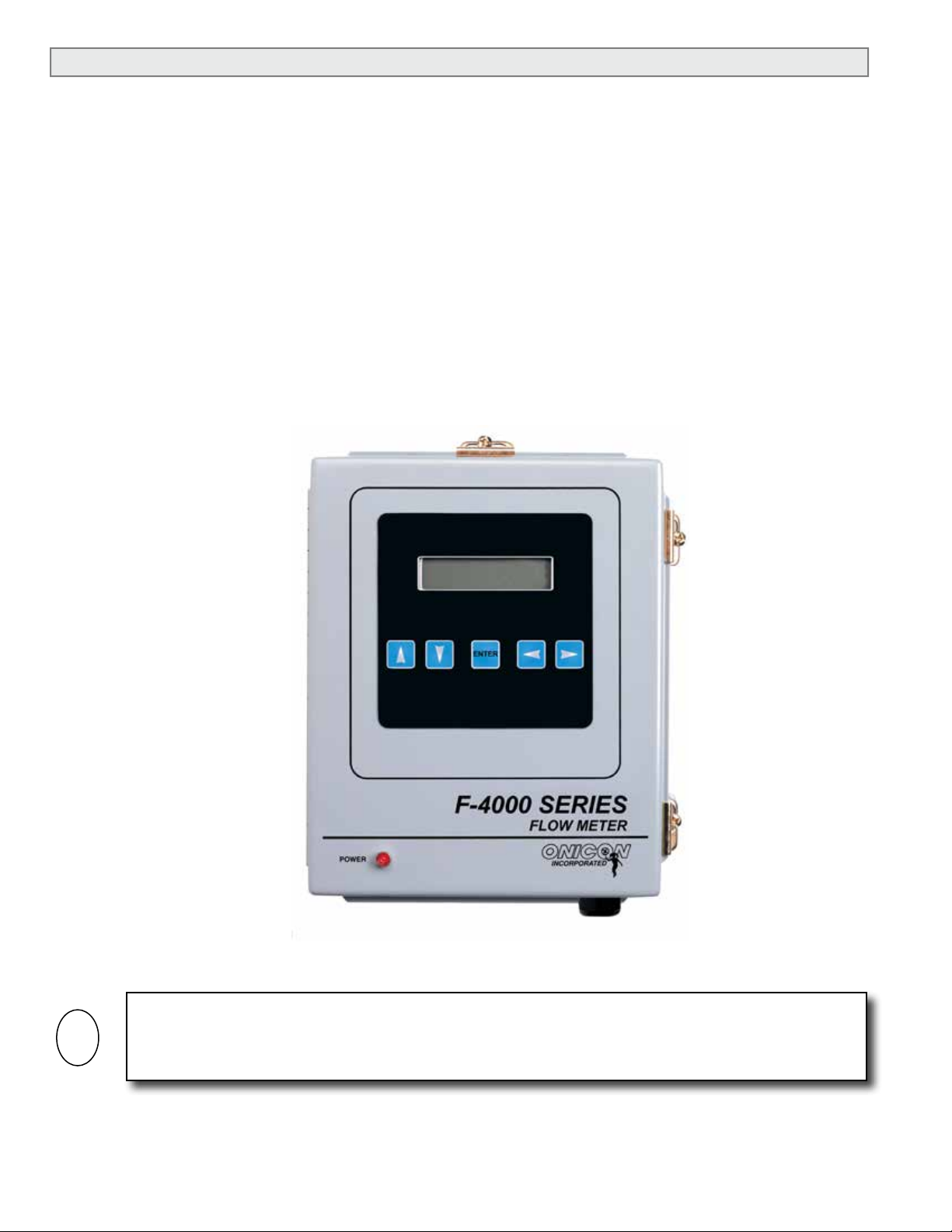
1.3 TYPICAL F-4000 FLOW METER
The F-4000 Series Ultrasonic Flow Meter utilizes clamp-on signal transducers that mount on
the outside wall of the pipe. It is suitable for measuring the volumetric ow of liquids in a wide
variety of applications including bi-directional ow applications. The meter is housed in a steel
wall-mounted enclosure with a built-in user interface/display.
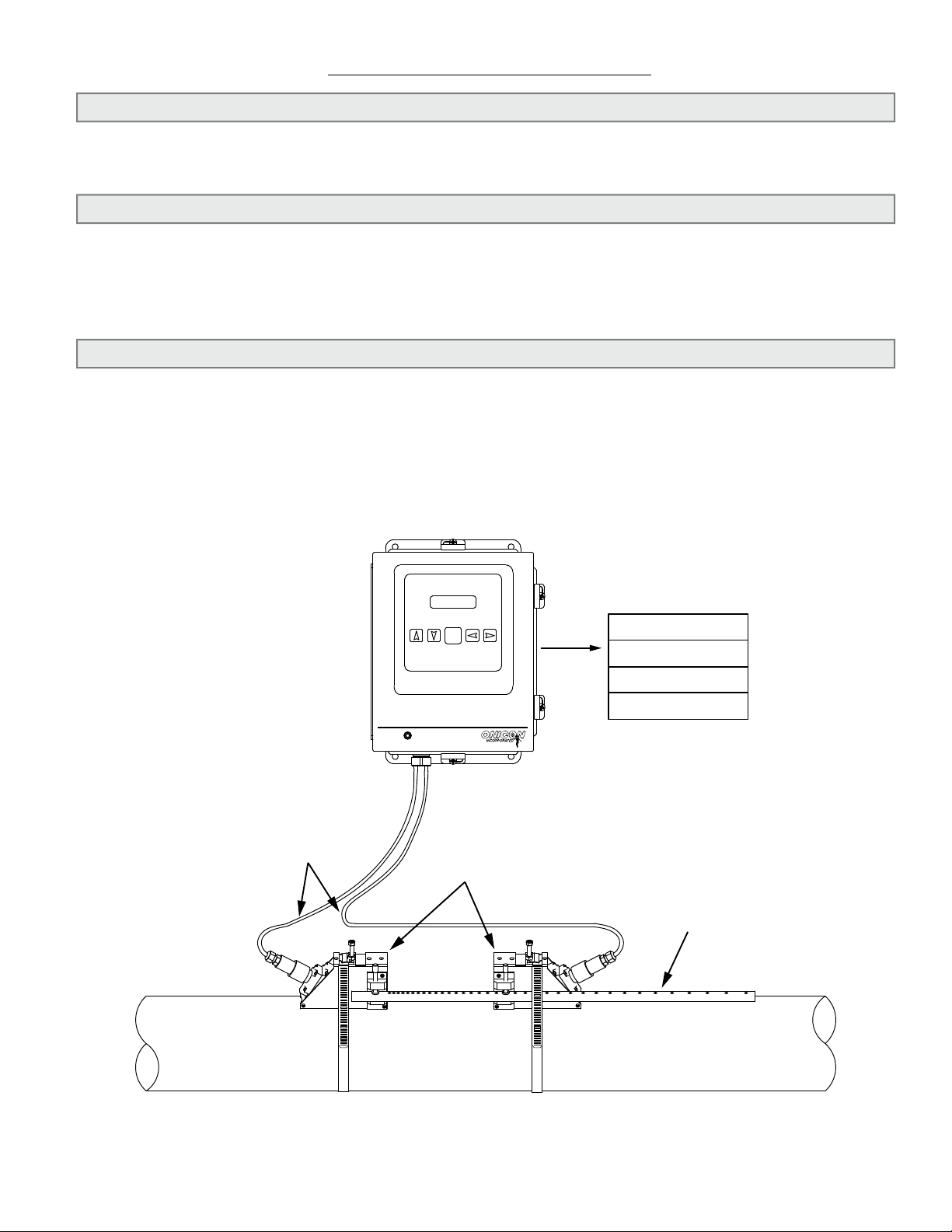
TYPICAL INSTALLATION
Coaxial
Transducer
Cables
POWER
ENTER
F-4000 SERIES
FLOW METER
Precision
Matched
Transducers
OUTPUT SIGNALS
4-20mA
Scaled Pulse
Relay Output
Mounting
Hardware
11451 Belcher Road South, Largo, FL 33773 • USA • Tel +1 (727) 447-6140 • Fax +1 (727) 442-5699 • sales@onicon.com
F-4000 Series Ultrasonic Flow Meter Manual 05/15 - 0707-13 / 18838 Page 5
Page 6

1.4 STANDARD FEATURES AND SPECIFICATIONS
• Wall-mounted NEMA 4 steel enclosure with 2-line alphanumeric user interface/display
• One externally powered electrically isolated 4-20 mA analog output for ow rate
• One scalable electrically isolated open collector pulse output for totalizing ow
• One programmable form C relay to indicate ow direction or alarm.
GENERAL SPECIFICATIONS
ACCURACY
± 1.0% of reading from 1 to 40 ft/sec
± 0.01 ft/s for velocities below 1 ft/sec
OVERALL FLOW RANGE
0.1 to 40 ft/sec
SENSING METHOD
Clamp-on ultrasonic, differential transit time
method in direct or reect mode
PIPE SIZE RANGE
½” through 48” nominal diameter
PROGRAMMING
Factory programmed for specic application
MEMORY
Non-volatile memory retains all program
parameters and totalized values in the event of
power loss.
DISPLAY
Alphanumeric 2-line, 16-characters per line
multifunction LCD display
(Character height, 0.2”)
Displays total ow, ow rate, speed of sound,
% gain, % aeration, signal strength, ow
direction & alarm conditions
Rate display range: 0 - 9,999,999
Totalizer display range: 0 – 99,999,999
Totalizers will roll over to zero when maximum
count is exceeded.
OUTPUT SIGNALS PROVIDED
Analog output: Electrically isolated 4-20 mA
(Externally powered 10 – 30 VDC)
Scalable pulse output: Optically isolated open
collector (Contact rating: 30 VDC, 10 mA
maximum, pulse duration: 50 ms)
Relay output for ow direction or alarm:
Programmable form C relay (Contact rating: 30
VDC, 250 mA maximum)
FLUID TEMPERATURE RANGE
Standard: -40° F to 250° F
Optional: High Temperature -40° F to 446° F
AMBIENT OPERATING TEMPERATURE RANGE
14° F to 122° F
STORAGE TEMPERATURE RANGE
-4˚ F to 140˚ F
MECHANICAL
MATERIALS OF CONSTRUCTION
Electronics enclosure: Wall-mount, powder coat
painted steel enclosure with stainless steel
hardware
Transducer mounting hardware: Anodized
aluminum and stainless steel
Transducers: Anodized aluminum and plastic
ENCLOSURE RATINGS
NEMA 4, weathertight
ELECTRICAL
This equipment is intended for INSTALLATION
CATEGORY (OVERVOLTAGE CATEGORY) II
applications. Installations must comply with all local,
state and federal building codes.
INPUT POWER – Factory selectable
11.5 to 28.5 VDC, 10 Watts maximum
(Internal: 5x20mm, 250V/2.0A fuse)
90-240 VAC 50/60 Hz, 15 VA maximum
(Internal: 5x20mm, 250V/0.5A fuse)
OVERCURRENT PROTECTIVE DEVICE RATINGS:
Supply mains overcurrent protective devices with
the following ratings:
120 VAC 50/60 Hz – 15 A
230 VAC 50 Hz – 6 A
ELECTRICAL CONNECTIONS
Enclosed terminal connections, cable access through
four standard ¾” conduit openings
Transducer signals: (2) F-connectors supplied with
quick-disconnect adapters
Input power: 3 terminal removable connectors
(12 – 22 AWG)
Signal inputs/outputs: PCB mount terminal blocks
(14 – 26 AWG)
WIRING
Transducer signals: Use Belden 9269 coaxial cable or
equivalent (93Ω nominal impedance)
24 VDC input power: Use PVC jacketed copper cable
with a wire gauge suitable for the length of run and
required maximum current carrying capacity.
Provide a separate protective earth wire.
120/230 VAC input power: Use a 3-wire service
with one wire a protective earth ground.
Signal inputs/outputs: Use PVC jacketed copper
shielded cable with a wire gauge suitable for the
length of run and required maximum current
carrying capacity.
11451 Belcher Road South, Largo, FL 33773 • USA • Tel +1 (727) 447-6140 • Fax +1 (727) 442-5699 • sales@onicon.com
F-4000 Series Ultrasonic Flow Meter Manual 05/15 - 0707-13 / 18838 Page 6
Page 7

1.5 MAINTENANCE
Periodically inspect the power cables, transducer cables, cable glands and the enclosure for signs
of damage. Inspect transducer installation and mounting hardware for loose connections.
1.6 ADDITIONAL REQUIRED HARDWARE
Installation hardware: ONICON clamp-on ultrasonic ow meters typically require installation
hardware. Hardware requirements vary by pipe size and material.
1.7 ADDITIONAL HARDWARE THAT MAY BE REQUIRED
Flex conduit may be required to connect transducer to rigid conduit. Do not connect transducers
to rigid conduit.
1.8 WORKING ENVIRONMENT
The F-4000 was designed for installation and use in typical commercial/industrial environments.
The following considerations must be observed in selecting a location for the meter:
• The ambient operating temperature range is 14° F (-10° C) to 122° F (50° C).
• Do not expose the meter to corrosive liquids or fumes.
• Avoid installation locations that are close to strong sources of electrical interference.
• Avoid installing the electronics enclosure in direct sunlight.
• Avoid installation locations where the transducers will be exposed to vibrations in the
piping system.
• Always run transducer cables in dedicated conduit separate from signal and power cables.
• Do not run signal cables for the meter in conduit with mains (AC) power cables.
1.9 WARRANTY & SERIAL NUMBER
Warranty
ONICON provides a 2-year warranty for this product. Certain exclusions apply. Please refer to
ONICON’s Conditions of Sale for details.
Serial Number
The serial number of your F-4000 is located outside and inside the enclosure. All components
of your F-4000 (electronics enclosure & transducers) will bear identical serial numbers. Serial
numbers are unique identiers that you should have available when contacting ONICON for
assistance regarding your meter.
11451 Belcher Road South, Largo, FL 33773 • USA • Tel +1 (727) 447-6140 • Fax +1 (727) 442-5699 • sales@onicon.com
F-4000 Series Ultrasonic Flow Meter Manual 05/15 - 0707-13 / 18838 Page 7
Page 8

SECTION 2.0: UNPACKING
i
The F-4000 is generally shipped in one package unless optional hardware or equipment is ordered.
Notify the freight carrier (all products are shipped insured) and ONICON if any items are damaged in transit.
2.1 CHECKING THAT YOU HAVE RECEIVED EVERYTHING
• Standard Documentation
Enclosed with each F-4000 is a comprehensive documentation package that includes the
following items:
This F-4000 Ultrasonic Flow Meter Installation and Operation Guide
The Flow Meter Certicate of Calibration
Site Installation Details Document
Please notify ONICON if any of these items are missing.
IMPORTANT NOTE
The ONICON F-4000 Ultrasonic Flow Meter is a custom calibrated system. Unless specically noted
in writing by ONICON, ALL COMPONENTS (electronics enclosure and ultrasonic transducers)
share the same serial number and must be installed together as a system. Mixing components from
different systems will result in signicant errors in calibration.
• The Wall Mount Enclosure
Remove the F-4000 enclosure from the shipping carton and inspect it inside and out for
physical damage. Please notify ONICON immediately if you discover any damage.
Transducers are shipped in the same carton with the enclosure. Inspect the transducers for
signs of damage. Each transducer will have a label attached with a serial number identical to
that found on the F-4000 enclosure. Included with the transducers are two dry coupling pads
and one tube of coupling compound.
• Transducers Cables
Transducer cables are coiled and packed separately in the outer carton. Taped to the cables
is a termination kit that includes the ttings necessary to terminate the transducer end of the
cables. The other end of each cable is already terminated.
• Installation Hardware
Installation hardware may include mounting brackets and a spacer bar or a track mount
assembly. Taped to this hardware will be a mounting strap kit. This kit includes the mounting
straps used to secure the hardware onto the pipe, a sanding block for preparing the pipe
surface, and a mylar mounting guide used when mounting transducers in direct operating
mode. The kit will also include a copy of the F-4000 Site Installation Details for this meter.
This document provides specic details such as transducer spacing. This information is
unique to the specic installation site and is identied by the meter location tag name and the
serial number of the meter.
11451 Belcher Road South, Largo, FL 33773 • USA • Tel +1 (727) 447-6140 • Fax +1 (727) 442-5699 • sales@onicon.com
F-4000 Series Ultrasonic Flow Meter Manual 05/15 - 0707-13 / 18838 Page 8
Page 9
SECTION 3.0: INSTALLATION
3.1 OVERVIEW
Each F-4000 Series Ultrasonic Flow Meter is provided with a pair of precision matched ultrasonic
transducers. The transducers are mounted (clamped) on to the outside wall of the pipe. Coaxial
cables convey the transducer signals to the wall mount enclosure containing the signal processing
circuitry and the user interface display. Ultrasonic transducers can be congured to operate
in either reect or direct operating modes. The choice of operating mode is dictated by the
conguration settings programmed into the meter. For new installations, conguration data is
programmed into the meter prior to shipment. This data is saved as a “Site”. Site data determines
the transducer operating mode and the spacing between the transducers. This information is
provided with the installation hardware in a document titled, “F-4000 Site Installation Details”.
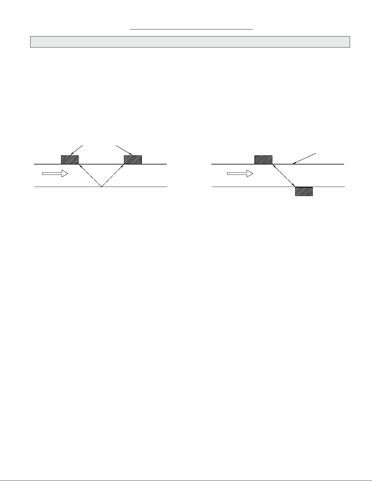
Transducers
Flow Flow
Reflect Mode
Direct Mode
Pipe Wall
Reect Mode
Reect mount is the recommended operating mode whenever possible. It is the simplest way
to mount the transducers. Operating in the reect mode also minimizes the effects of some ow
distortions and enables the use of the auto zero function.
Direct Mode
Direct mount provides a shorter sonic beam path. This usually improves performance with
sonically attenuative liquids or pipe materials. Direct mount is required for plastic pipes. Direct
mounting only requires half the distance between electrodes when compared to the reect mode
and may be the only option if the availability of mounting space is limited.
11451 Belcher Road South, Largo, FL 33773 • USA • Tel +1 (727) 447-6140 • Fax +1 (727) 442-5699 • sales@onicon.com
F-4000 Series Ultrasonic Flow Meter Manual 05/15 - 0707-13 / 18838 Page 9
Page 10
3.2 SITE SELECTION
i
Careful attention to the site selection for the system components will help the installers with the
initial installation, reduce start-up problems and make future maintenance easier. For example,
do not install the meter where it will be difcult for personnel to perform periodic maintenance.
When selecting a site for mounting the system components, consider the criteria under Section
1.8 WORKING ENVIRONMENT, as well as the following:
The Wall-Mount Enclosure
Find an easily accessible location where wire connections can be made and meter readings can
be taken from oor level. Mount the enclosure on a vibration-free surface. Avoid sites such as
the plenum of a fan coil, heat exchanger, or other housings containing motors. Avoid mounting
the enclosure in close proximity to VFD’s, electric motors or other strong sources of electrical
interference.
IMPORTANT NOTE
The maximum allowable distance between the wall-mount enclosure and the transducers installed
on the pipe is 300 feet.
11451 Belcher Road South, Largo, FL 33773 • USA • Tel +1 (727) 447-6140 • Fax +1 (727) 442-5699 • sales@onicon.com
F-4000 Series Ultrasonic Flow Meter Manual 05/15 - 0707-13 / 18838 Page 10
Page 11
i
The Transducers
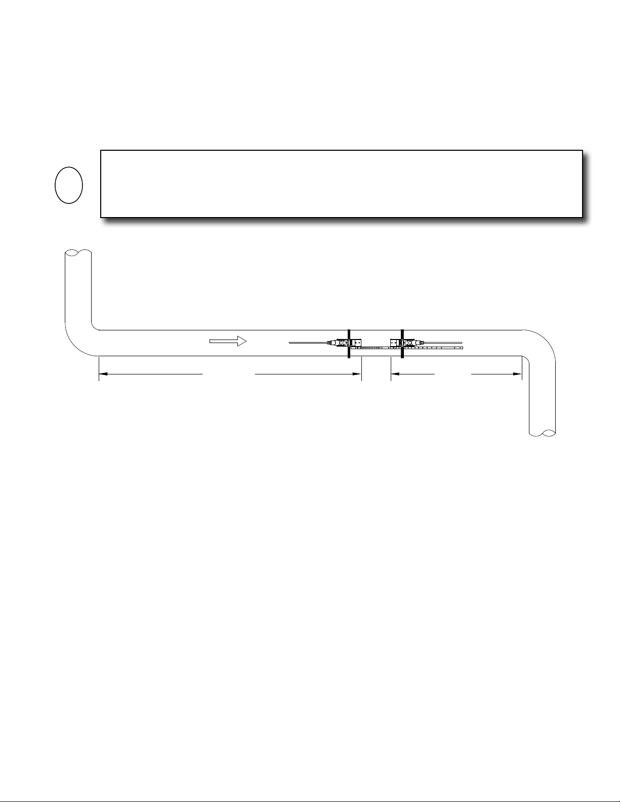
For best results, the transducers must be installed on a straight run of pipe, free of bends, tees,
valves, transitions, insertion probes and obstructions of any kind. For most installations, ten
straight unobstructed pipe diameters upstream and ve diameters downstream of the transducers
is the minimum recommended distance for proper operation. Additional considerations are
outlined below.
IMPORTANT NOTE
In some cases, longer straight runs may be necessary where the transducers are placed downstream
from devices which cause unusual ow prole disruptions or swirl; for example, modulating valves
or two elbows in close proximity and out of plane, etc.
Flow
10 Dia. 5 Dia.
• Do not, if possible, install the transducers downstream from a throttling valve, a mixing tank,
the discharge of a positive displacement pump or any other equipment that could possibly
aerate the liquid. The best location will be as free as possible from ow disturbances,
vibration, sources of heat, noise, or radiated energy.
• Avoid mounting the transducers on a section of pipe with any external scale. Remove all
scale, rust, loose paint, etc., from the location prior to mounting the transducers.
• Do not mount the transducers on a surface aberration (pipe seam, etc.).
• Do not mount transducers from different ultrasonic ow meters on the same pipe.
• Do not run the transducer coaxial cables in common bundles with cables from other
instrumentation. You can run these cables through a common conduit ONLY if they originate
at the same ow meter.
• Never mount transducers under water, unless you have specically purchased submersible
transducers and you install them in accordance with factory instructions.
• Avoid mounting transducers on the top of a horizontal pipe. The best placement on a
horizontal pipe is either the 10:00 or 2:00 position for reect mode, or one sensor at 9:00 and
one sensor at 3:00 for direct mode.
• Do not mount transducers on the bottom of a horizontal pipe.
• Mounting on a vertical pipe is recommended only if ow is in the upward direction. When
mounting on a vertical pipe owing in a downward direction, make sure there is sufcient
back pressure in the system to maintain a full pipe.
11451 Belcher Road South, Largo, FL 33773 • USA • Tel +1 (727) 447-6140 • Fax +1 (727) 442-5699 • sales@onicon.com
F-4000 Series Ultrasonic Flow Meter Manual 05/15 - 0707-13 / 18838 Page 11
Page 12
!
i
3.3 MECHANICAL INSTALLATION
This ONICON F-4000 Ultrasonic Flow Meter is a custom calibrated system. Unless specically
noted in writing by ONICON, ALL COMPONENTS (electronics enclosure and precision matched
transducers) share the same serial number and must be installed together as a system. Mixing
components from different systems will result in signicant errors in calibration.
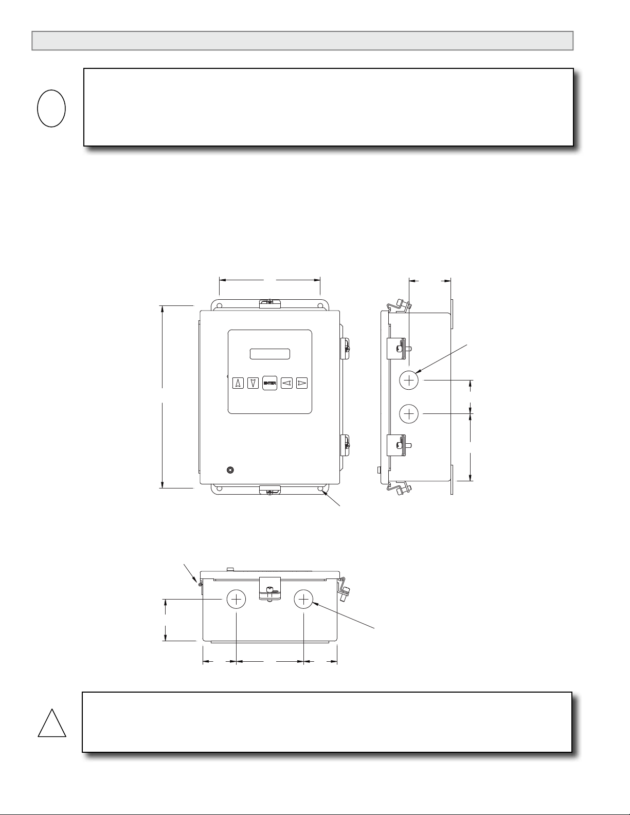
3.3.1 Mounting the Enclosure
Find an easily accessible location where electrical connections can be made and meter
readings can be taken from the oor level. Mount the enclosure on a vibration-free
surface. Avoid sites such as the plenum of a fan coil, heat exchanger, or other housings
containing motors. Avoid mounting the enclosure in close proximity to VFD’s, electric
motors or other strong sources of electrical interference.
IMPORTANT NOTE
6” 2.5”
10.75”
Hinge side shown
for refernce.
2.5”
2xØ1.115
2”
4”
4xØ0.312
2xØ1.115
2”
4”
2”
CAUTION
Do not drill additional holes in this enclosure. Doing so may damage the electronic circuitry
contained within and will void all warranties.
11451 Belcher Road South, Largo, FL 33773 • USA • Tel +1 (727) 447-6140 • Fax +1 (727) 442-5699 • sales@onicon.com
F-4000 Series Ultrasonic Flow Meter Manual 05/15 - 0707-13 / 18838 Page 12
Page 13
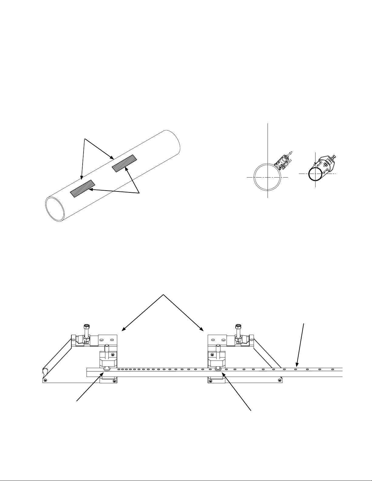
3.3.2 Preparing the Pipe
Once a suitable section of straight pipe has been located, the pipe surface must be
prepared. Refer to the Site Installation Details document provided with the installation
hardware to determine the transducer spacing dimensions. Prepare the pipe surface as
shown below. Clean and de-grease two rectangles where the transducers will be located.
Use the small sanding block provided with the installation hardware as necessary to
remove any grit, corrosion, rust, loose paint or other contaminants. The cleaned surface
should extend at least ½” beyond the length and width of the transducers.
Always install hardware at the 10:00 or 2:00 position on horizontal pipes. This prevents
the ow meter from being affect by air trapped at the top of the pipe.
Refer to site installation details
document for transducer spacing.
Prepare mounting
locations for transducers.
3.3.3 Reect Mode Mounting Using Frames and Spacer Bar
1. Prepare the pipe surface as described in section 3.3.2.
2. On a at surface, assemble the hardware as shown in the drawing below.
Orient mounting brackets as shown.
For horizontal pipes, locate transducers at
the 10:00 or 2:00 position.
Numbered index holes
Reference hole
Refer to the Site Installation Details document
provided with the installation hardware to
determine the correct hole location.
11451 Belcher Road South, Largo, FL 33773 • USA • Tel +1 (727) 447-6140 • Fax +1 (727) 442-5699 • sales@onicon.com
F-4000 Series Ultrasonic Flow Meter Manual 05/15 - 0707-13 / 18838 Page 13
Page 14
Spring clip
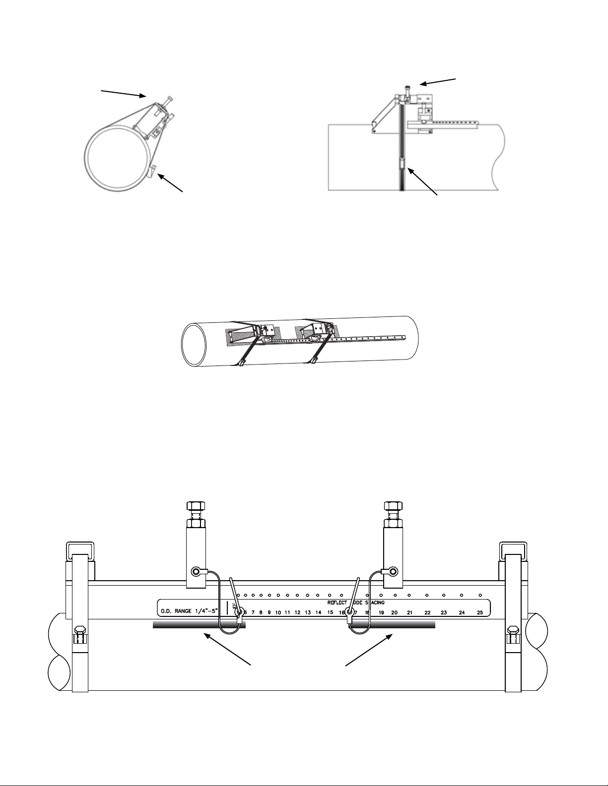
3. Install the mounting straps as shown below. For larger pipes, use multiple straps
connected end-to-end to increase the length of each strap. Leave enough slack in the
straps to allow the assembly to be correctly positioned on the pipe.
Wrap the rst mounting strap
around the pipe and under the
spring clip on top of the mounting
bracket. Make sure to position
it so there is easy access to the
adjustment screw. Repeat this
procedure for the second mounting
bracket.
Adjustment screw Adjustment screw
Spring clip
4. Move the hardware assembly to its nal position on the pipe. Align the brackets
with the prepared surface for each transducer as shown below, ensuring that the
entire assembly is properly oriented along the axis of the pipe. Tighten the assembly
rmly on the pipe. Do not over tighten the straps.
3.3.4 Reect Mode Mounting Using Track Mount Hardware
1. Prepare the pipe surface as described in section 3.3.2.
2. Place the track mount hardware assembly at the 10:00 or 2:00 position on the pipe at
the desired mounting location. Ensure that it is a clean, smooth area without any raised
spots or seams.
TRACK 4 00
Prepared Surfaces
11451 Belcher Road South, Largo, FL 33773 • USA • Tel +1 (727) 447-6140 • Fax +1 (727) 442-5699 • sales@onicon.com
F-4000 Series Ultrasonic Flow Meter Manual 05/15 - 0707-13 / 18838 Page 14
Page 15
3. Holding the track mount assembly in place, wrap one of the mounting straps around
the pipe as shown in the drawing below. Tighten the tension screw enough to hold the
assembly on the pipe, but still allow rotation. Repeat for the other mounting strap.
Mounting Strap Mounting Strap
TRACK 4 00
Prepared Surfaces
4. Rotate the track mount assembly as necessary to its nal itended mounting position
on the pipe, then tighten both tension screws just enough to prevent rotation. Do not
over tighten.
11451 Belcher Road South, Largo, FL 33773 • USA • Tel +1 (727) 447-6140 • Fax +1 (727) 442-5699 • sales@onicon.com
F-4000 Series Ultrasonic Flow Meter Manual 05/15 - 0707-13 / 18838 Page 15
Page 16
3.3.5 Direct Mode Mounting Using Brackets and Spacer Bar
i
1. Once the installation site selection process described in section 3.2 is complete,
prepare the pipe where the rst sensor will be mounted.
IMPORTANT NOTE
Direct mode mounting requires that transducers be installed on opposite sides of the pipe. For
horizontal pipes, the transducers should be located at the 3 o’clock and 9 o’clock positions.
2. To prepare the pipe, temporarily position a mounting bracket on the pipe where you
will be mounting it. Ensure that the pipe surface is smooth without any raised areas
(seams, etc.) With a pencil, marker or chalk, draw a generous rectangle around the
bracket. Clean and de-grease the area within the rectangle. Use the small sanding block
provided with the installation hardware as necessary to remove any grit, corrosion,
rust, loose paint or other contaminants. Be sure to wipe the surface clean after sanding.
The cleaned surface should extend at least ½” beyond the length and width of the
mounting bracket.
3. Attach the spacer bar to one of the mounting brackets at the reference hole.
Clamping Screw
Spacer Bar
Reference Hole
11451 Belcher Road South, Largo, FL 33773 • USA • Tel +1 (727) 447-6140 • Fax +1 (727) 442-5699 • sales@onicon.com
F-4000 Series Ultrasonic Flow Meter Manual 05/15 - 0707-13 / 18838 Page 16
Page 17

4. Position the mounting bracket and spacer bar in the center of the cleaned area and
secure it in place with a mounting strap as shown below. Make sure the mounting
strap tightening screw is facing up. Note that the angled end of the bracket must be
facing away from where the other bracket will be mounted. While tightening the strap,
check to ensure that the bracket remains centered on the pipe. (The bracket is centered
on the pipe when the bottom edges of both aluminum side plates on the bracket are in
full contact with the pipe surface.)
5. Attach the second bracket to the spacer bar at the numbered index hole specied on
the site installation details document provided with the installation hardware. Note
that the angled end of the bracket must be facing away from the other mounting
bracket.
Orient mounting brackets as shown.
Numbered index holes
Reference hole
Refer to the Site Installation Details document
provided with the installation hardware to
determine the correct hole location.
6. Check to ensure that this bracket is lined up on the center of the pipe. While holding
the bracket centered on the pipe, place a mark (with pencil or chalk) at the center of
the tapered roller at the bottom of the bracket as shown below. Next, mark along the
edge of the bracket as indicated in the drawing below.
Place mark at center
of tapered roller.
11451 Belcher Road South, Largo, FL 33773 • USA • Tel +1 (727) 447-6140 • Fax +1 (727) 442-5699 • sales@onicon.com
F-4000 Series Ultrasonic Flow Meter Manual 05/15 - 0707-13 / 18838 Page 17
Draw line along edge
of bracket.
Page 18

7. Remove the bracket from the spacer bar and then remove the spacer bar from the
1.5869
bracket that is strapped to the pipe. Using the spacer bar as a straight edge, draw a line
down the center of the pipe intersecting the mark made at the center of the tapered
roller and the line drawn against the edge of the bracket as shown below.
1.5869
Spacer bar
Draw line using spacer
bar as edge.
8. Wrap the Mylar spacing guide around the pipe so that the left edge is against the
transducer edge mark. Arrange so that one end overlaps the other. Ensure that it is
snug around the pipe and mark along the overlapping edge.
Draw the guide tightly
Mylar spacing guide
around the pipe and mark
at the overlapping edge.
9. Remove Mylar spacing guide and lay it out on a at surface. Either measure the exact
distance half-way between the overlap edge and the mark at the overlap, or fold the
guide from the overlap edge to overlap mark and draw a line at the fold or halfway
point.
50%
50%
Overlap edge mark
10. Reinstall the spacing guide; its edge abutting the bracket edge mark on the pipe and the
overlapping edge in line with the line drawn down the center of the pipe. Tape it in
this position on the pipe. Take the second bracket and place it against the edge of the
guide with its tapered roller centered on the half way mark drawn on the guide.
Mylar spacing guide aligned
with marks on pipe.
Bracket aligned with edge of
guide and centered on marks
on the guide.
11451 Belcher Road South, Largo, FL 33773 • USA • Tel +1 (727) 447-6140 • Fax +1 (727) 442-5699 • sales@onicon.com
F-4000 Series Ultrasonic Flow Meter Manual 05/15 - 0707-13 / 18838 Page 18
Page 19

11. Ensure that the bracket is sitting on a smooth area without any raised spots (seams,
etc.). Mark a generous rectangle around the bracket with a pencil, marker or chalk.
Remove the bracket and the Mylar guide.
12. Clean and de-grease the area within the rectangle. Use the small sanding block
provided with the installation hardware as necessary to remove any grit, corrosion,
rust, loose paint or other contaminants. The cleaned surface should extend at least ½”
beyond the length and width of the mounting bracket.
13. Replace the Mylar guide back in the same position it was in and re-tape it to the pipe.
14. Position the bracket as before against the edge of the guide with its tapered roller
centered on the half way mark drawn on the guide. Secure it in place with a mounting
strap as shown below. Make sure the mounting strap tightening screw is facing toward
the bracket so you can hold it in place while tightening the screw. Note that the angled
end of the bracket must be facing away from where the other bracket will be mounted.
While tightening the strap, check to ensure that the bracket remains centered on the
pipe. (The bracket is centered on the pipe when the bottom edges of both aluminum
side plates on the bracket are in full contact with the pipe surface.)
Mylar spacing guide aligned
with marks on pipe.
Bracket aligned with edge of
guide and centered on marks
on the guide.
11451 Belcher Road South, Largo, FL 33773 • USA • Tel +1 (727) 447-6140 • Fax +1 (727) 442-5699 • sales@onicon.com
F-4000 Series Ultrasonic Flow Meter Manual 05/15 - 0707-13 / 18838 Page 19
Page 20

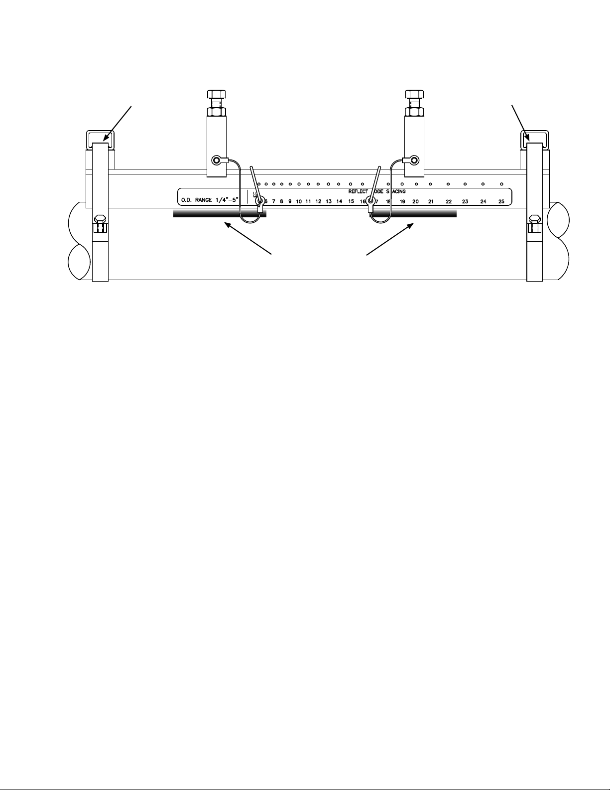
3.3.6 Direct Mode Mounting Using Track Mount Hardware
i
1. Once the installation site selection process described in section 3.2 is complete,
prepare the pipe where the rst sensor will be mounted.
IMPORTANT NOTE
Direct mode mounting requires that transducers be installed on opposite sides of the pipe. For
horizontal pipes, the transducers should be located at the 3 o’clock and 9 o’clock positions.
2. To prepare the pipe, temporarily position one track mount hardware assembly on each
side of the pipe where you intend to permanently mount them as shown below.
Ensure that pipe surface is smooth without any raised areas (seams, etc.) With a
pencil, marker or chalk, draw a rectangle around each track mount assembly. Remove
the hardware from the pipe and clean and de-grease the area within the rectangles. Use
the small sanding block provided with the installation hardware as necessary to
remove any grit, corrosion, rust, loose paint or other contaminants. Be sure to wipe
the surface clean after sanding. The cleaned surface should extend at least ½” beyond
the length and width of each assembly.
Mark pipe around each
track and clean within
the marked area.
TRACK 400
O.D. RANGE 1/4"-5"
TRACK 400
O.D. RANGE 1/4"-5"
0 1 4 53 86
2
REF
9
5 86
7
10
9
7
10
13
DIRECT MODE SPACING
12
13
REFLECT MODE SPACING
15
141211
15
1411
16
16
2019 21
18
17
2019 21
18
17
24 25
23
22
24 25
23
22
3. Re-install the two track mount hardware assemblies on the pipe and loosely secure
them in place with the mounting straps provided. Align the assemblies such that they
are positioned on top of the cleaned surfaces.
11451 Belcher Road South, Largo, FL 33773 • USA • Tel +1 (727) 447-6140 • Fax +1 (727) 442-5699 • sales@onicon.com
F-4000 Series Ultrasonic Flow Meter Manual 05/15 - 0707-13 / 18838 Page 20
Page 21

4. Wrap the Mylar spacing guide around the pipe placing it against the end of the track
mount assemblies. Ensure that it is snug around the pipe and mark along the
overlapping edge.
Wrap Mylar spacing guide
around pipe and mark
along overlapping edge.
TRACK 400
O.D. RANGE 1/4"-5"
TRACK 400
O.D. RANGE 1/4"-5"
0 1 4 53 86
2
REF
9
5 86
7
9
7
REFLECT MODE SPACING
15
141211
13
16
10
DIRECT MODE SPACING
15
1411
12
13
10
2019 21
18
17
16
2019 21
18
17
24 25
23
22
24 25
23
22
Draw the guide tightly
around the pipe and mark
at the overlapping edge.
5. Remove Mylar spacing guide and lay it out on a at surface. Either measure the exact
distance half-way between the overlap edge and the mark at the overlap, or fold the
guide from the overlap edge to overlap mark and draw a line at the fold or halfway
point.
Overlap edge mark
50%
50%
6. Reinstall the spacing guide and tape it in place. Use the edge of the guide to align each
assembly bracket as shown.
7. Rotate the track assemblies until the center of one track aligns with the center line
on the spacer guide, and the center of the other track aligns at the point where the
spacer guide ends meet. The tracks should now be 180° apart. Tighten both mounting
straps to secure the assembly to the pipe. Do not over tighten.
11451 Belcher Road South, Largo, FL 33773 • USA • Tel +1 (727) 447-6140 • Fax +1 (727) 442-5699 • sales@onicon.com
F-4000 Series Ultrasonic Flow Meter Manual 05/15 - 0707-13 / 18838 Page 21
Page 22

3.3.7 Installing Transducers In Bracket and Spacer Bar Hardware
1. Apply the dry coupling pad to the transducer as show below.
Apply a continuous
lengthwise 1/2” wide bead
of coupling compound
down the center of the
transducer.
2. This step only applies to reect mount transducers installed on copper and steel pipes.
For all other applications, skip to step 3.
Apply the dry coupling pad to the transducer as show below.
Place the dry coupling
pad on the transducer.
Gently press down just
enough to seat and center
the pad.
3. Slide the transducer into the mounting bracket back end rst, aligning the angled edge
of the transducer with the angled edge of the bracket. Do not allow the bottom of the
transducer to make contact with the pipe until it butts against the mounting bracket
stop. Push down rmly on the transducer to mate with pipe.
When installing the transducer,
do not allow the bottom face to
touch the pipe surface until it is
fully inserted to the stop.
Apply a second bead
of coupling compound
down the center of the dry
coupling pad.
11451 Belcher Road South, Largo, FL 33773 • USA • Tel +1 (727) 447-6140 • Fax +1 (727) 442-5699 • sales@onicon.com
F-4000 Series Ultrasonic Flow Meter Manual 05/15 - 0707-13 / 18838 Page 22
Page 23

REF
O.D. RANGE 1/4"-5"
6
7
5
Track 400
17
REFLECT MODE SPACING
13
9
10
8 12111514
16 1918202221232524
15.94
(405)
(71.1)
3.0
(76.2)
2.8
REF
O.D. RANGE 1/4"-5"
6
7
5
Track 400
17
REFLECT MODE SPACING
13
9
10
8 12111514
16 1918202221
23
CUSTOMER'S PIPE
2524
REF
O.D. RANGE 1/4"-5"
6
7
5
Track 400
9
10
8 11
15.94
(405)
4. Tighten the transducer clamping screw to hold the transducer rmly in place.
Do not over tighten the screw.
Transducer Clamping Screw
5. Repeat procedure for the second transducer.
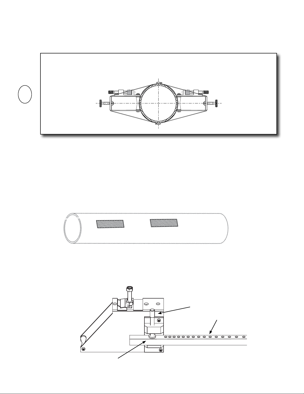
3.3.8 Installing Transducers In Track Mount Hardware
1. Insert the index pin into the reference hole.
Reference hole
Track 400
O.D. RANGE 1/4"-5"
REF
9
675
8 11
10
2. Repeat step 1 and 2 in Section 3.3.7 as necessary to apply couplant and pad to
tranducer.
3. Place the transducer between the track rails, slightly behind the pin and under the
clamping screw assembly. Slide it forward until it butts rmly against the reference
pin. Once the transducer is in place, secure it with the sensor clamping screw. Do not
over tighten.
Clamping screw
Track 400
O.D. RANGE 1/4"-5"
REF
9
675
8
10
4. Repeat procedure for the second transducer.
11451 Belcher Road South, Largo, FL 33773 • USA • Tel +1 (727) 447-6140 • Fax +1 (727) 442-5699 • sales@onicon.com
F-4000 Series Ultrasonic Flow Meter Manual 05/15 - 0707-13 / 18838 Page 23
Page 24

3.4 CONNECTING THE TRANSDUCER SIGNAL CABLES
!
ONICON F-4000 transducer cables are special purpose coaxial cables. Care must be taken when
installing the cables to ensure that electrical noise will not affect the performance of the meter.
The cables must NOT be bundled or run in conduit with any other signal or power cables. The
maximum allowable cable length is 300 ft.
To install the cables, rst locate and install the wall-mount electronics enclosure and the
transducers.
Strain relief provided
Strain relief provided
FLOW
TYPICAL INSTALLATION WITH CONDUIT
TYPICAL INSTALLATION WITHOUT CONDUIT
FLOW
The transducer cables are provided with connectors already
installed at one end of the cable. Install this end of each
cable at the electronics enclosure as shown below using the
right angle adapters provided. When installing the cable,
avoid routing it close to strong sources of electrical noise,
and do not install cables in raceways with power or other
signal cables.
Once the correct cable length has been determined, install
the F-connectors provided to terminate the end of each cable.
WARNING
For proper operation, cables must not be bundled or run in conduit with any other signal or power
cables.
ENCLOSURE END (REF.)
11451 Belcher Road South, Largo, FL 33773 • USA • Tel +1 (727) 447-6140 • Fax +1 (727) 442-5699 • sales@onicon.com
F-4000 Series Ultrasonic Flow Meter Manual 05/15 - 0707-13 / 18838 Page 24
Page 25

3.5 INSTALLING THE F-CONNECTORS
INSTRUCTIONS
9/16”
DIELECTRIC
CENTER
CONDUCTOR
5/16”
1/4”
CABLE
1/16” - 3/32” DIELECTRIC
EXTENDS BEYOND BRAID
COPPER BRAID
"F" CONNECTOR
CABLE
DIELECTRIC
CENTER
CONDUCTOR
1/16"
9/16”
DIELECTRIC
CENTER
CONDUCTOR
5/16”
1/4”
CABLE
1/16” - 3/32” DIELECTRIC
EXTENDS BEYOND BRAID
1/32” MAX. PROJECTION
OF DIELECTRIC
COPPER BRAID
Prior to installing the F-connectors, slide the upstream and downstream cable markers over the
ends of the cables followed by the strain relief and NPT adapters.
3.5.1 Cable Preparation
Strip and trim to length as shown. Do not push copper braid back over jacket.
3.5.2 Cable & Connector Assembly
3.5.3 Final Assembly
9/16”
CABLE
Thread cable into connector until the dielectric slightly protrudes from the end of the
barrel. The center conductor should protrude approximately 1/16” beyond the connector
1/4”
1/16” - 3/32” DIELECTRIC
EXTENDS BEYOND BRAID
COPPER BRAID
DIELECTRIC
CENTER
CONDUCTOR
5/16”
body as shown.
1/32” MAX. PROJECTION
OF DIELECTRIC
CABLE
"F" CONNECTOR
CENTER
CONDUCTOR
DIELECTRIC
1/16"
11451 Belcher Road South, Largo, FL 33773 • USA • Tel +1 (727) 447-6140 • Fax +1 (727) 442-5699 • sales@onicon.com
F-4000 Series Ultrasonic Flow Meter Manual 05/15 - 0707-13 / 18838 Page 25
Place shrink tubing over the connector and shrink in place with hot air gun.
CABLE
SHRINK SLEEVE
(DWP125 - 1/2 X 3/4”)
F-CONNECTOR
P/N SPCF 59 I
1/8” (MIN)
Page 26

!
3.6 ELECTRICAL INSTALLATION
!
!
!
All user supplied conduit ttings, junction boxes, etc. must be installed in compliance with
federal, state and local building codes.
3.6.1 Input Power Options
The F-4000 can be ordered with two different input voltage options. This is not user
selectable in the eld. The input power options are:
11.5 - 28.5 VDC, 10 Watts maximum
90 - 240 VAC 50/60 Hz, 15 VA maximum
WARNING
Conduit openings in the F-4000 enclosure must be closed with UL listed ttings applicable to NEMA
4 enclosures.
WARNING
The protective earth connection must be made as shown in Section 3.6.2. Failure to do so will result
in an increased risk of injury.
WARNING
All mains voltage connections must be made through the pre-drilled conduit/strain relief opening
located at the bottom of the enclosure. Failure to do so will result in an increased risk of injury.
CAUTION
This product must be connected to earth ground for proper operation. Failure to do so may result in
erratic operation.
11451 Belcher Road South, Largo, FL 33773 • USA • Tel +1 (727) 447-6140 • Fax +1 (727) 442-5699 • sales@onicon.com
F-4000 Series Ultrasonic Flow Meter Manual 05/15 - 0707-13 / 18838 Page 26
Page 27

3.6.2 Electrical Connections
!
WARNING
Turn off mains power at the source prior to making power connections to the F-4000. Contact with
exposed live wiring may result in electric shock, burns and/or serious injury.
Protective Earth
ACDCHOT
POS +
NEU
NEG -
GND
GND
AC 90 - 240 VAC 50/60 Hz
DC 11.5 - 28.5 VDC
TB1
TB-1
I OUT 1
TB-2
TB-3
TB-4
RELAY 1 DIGITAL IN1 DIGITAL IN2
TB-5
TB-6
TB-7
TB-8
TB-9
TB-10
TB-11
TB-12
TB-13
TB-14
PGEN
TB-15
TB-16
See the table on the next page for text block 1 wiring connections.
11451 Belcher Road South, Largo, FL 33773 • USA • Tel +1 (727) 447-6140 • Fax +1 (727) 442-5699 • sales@onicon.com
F-4000 Series Ultrasonic Flow Meter Manual 05/15 - 0707-13 / 18838 Page 27
Page 28

Analog Output (IO1)
Term # Function Description
1 (+) 4 - 20 loop supply
2 (-) 4 - 20 loop return
Loop (externally) powered
4 - 20 mA output
3 Shield
RL=250 W typical, 750 W maximum
Vc=24 VDC typical / 30 VDC maximum
USER CONNECTIONS F-4000 INPUTS AND OUTPUTS
30Vd c
V
c
max
R
= 0 to 750
L
Relay Output (RELAY OUTPUT)
Term # Function Description
4 Common Relay Common
5 Normally Open Relay Output
6 Normally Closed Relay Output
7 Shield
RL=300 W minimum
Digital Inputs (NO TOT, CLR TOT)
Term # Function Description
8 (+) No Totalizer
9 (-) No Totalizer
Digital input used to inhibit
totalizer
10 Shield
11 (+) Reset Totalizer Digital input used to reset
totalizer to zero
12 (-) Reset Totalizer
13 Shield
Vc=2-10VDC; Then R
Vc=>10≤30VDC; Then R
=OW
L
=(Vc-10)/.02
L
30Vd c
V
c
max
ION= 100
ION= 4
V
c
= 4
I
ON
V
c
(min)
30Vd c
max
(min)
30Vd c
max
- 20
- 20
(max)
(max)
(max)
R
mA
mA
mA
C
L
NO
NC
R
L
R
L
500Ω
500Ω
Pulse Output (PULSE OUTPUT)
Term# Function Description
14 (+) Pulse Output Programmable pulse
ION= 10
30Vd c
V
c
max
(max)
mA
R
L
output. Optically isolated
(externally powered) open
V
o
collector.
15 (-) Pulse Output
16 Shield
Vc= +30 VDC maximum
RL = 3K W minimum
11451 Belcher Road South, Largo, FL 33773 • USA • Tel +1 (727) 447-6140 • Fax +1 (727) 442-5699 • sales@onicon.com
F-4000 Series Ultrasonic Flow Meter Manual 05/15 - 0707-13 / 18838 Page 28
Page 29

SECTION 4.0: START-UP
i
Each time an F-4000 ow meter is installed on a pipe, a new installation “site” must be created or
an existing site must be recalled from memory. An installation “site” contains all of the operating
parameters required to congure the meter for one specic installation. If it does not exist, it must be
created before the meter can measure ow.
ONICON F-4000 ow meters are normally shipped with the intended installation site pre-programmed
into the memory of the meter. This pre-programmed site was created and stored in the memory at the
ONICON factory and is based on installation data provided to ONICON when the meter was ordered.
The information programmed into the site is also provided in a document that accompanies the
installation hardware. It is titled, “Site Installation Details”.
If the information contained in the Site Installation Details document matches that specic installation
location, then the stored site can be recalled as per section 4.2 below. If there is any discrepancy, the
site must be edited and resaved before it is used. Contact ONICON for assistance in editing or creating
a new site.
Once a site has been recalled and loaded into active memory, the transducers can be activated by using
the “Install” function. During this process the meter will automatically select the optimum operating
frequency and establish a speed of sound reading for the uid in the pipe. Depending on the pipe
material and the operating mode (reect or direct) the meter may also adjust for any zero offsets and set
the level for the empty pipe detector.
4.1 PROGRAM MODE KEYPAD FUNCTIONS
Keypad Pushbuttons Description of functions in program mode
Enter program mode or save selected option or numeric entry.
Right enters menu function or moves down to lower level menu.
Left exits menu function or moves up to higher menu level.
Used to scroll up and down through menu or option lists.
IMPORTANT NOTE
When powering the meter for the rst time, a splash screen message may scroll across the display.
This will only happen when no site is installed.
11451 Belcher Road South, Largo, FL 33773 • USA • Tel +1 (727) 447-6140 • Fax +1 (727) 442-5699 • sales@onicon.com
F-4000 Series Ultrasonic Flow Meter Manual 05/15 - 0707-13 / 18838 Page 29
Page 30

4.2 RECALLING A SAVED SITE
i
If this is the rst time the meter is installed, conrm that the site to be recalled matches the actual installation as
described above. This can be done by reviewing the Site Installations Detail document provided with the meter.
The procedure below is used to recall a saved site and load it into active memory. Recalling a site will
automatically over write any previously loaded site.
IMPORTANT NOTE
Choose the appropriate site from those listed. The site created at the ONICON factory is the serial
number of the meter. “Z” sites are factory defaults, and should not be used without rst consulting
ONICON technical service.
If at any time you wish to return to the beginning of this procedure, press repeatedly
until you arrive at Step#1.
Step
1.
2.
3.
4.
5.
6.
Press the Following
Keypad Pushbutton
(Press as necessary)
Displayed Information
(After Keypress)
Comment
Choose the appropriate site from those listed. The
correct site is the serial number of the meter. “Z”
sites are factory defaults, and should not be used.
7.
8.
9.
11451 Belcher Road South, Largo, FL 33773 • USA • Tel +1 (727) 447-6140 • Fax +1 (727) 442-5699 • sales@onicon.com
F-4000 Series Ultrasonic Flow Meter Manual 05/15 - 0707-13 / 18838 Page 30
Page 31

4.3 INSTALLING RECALLED SITES
When you “Install” a site, you activate the transducers so the meter can read ow. During this process,
the meter will select the best operating frequency and establish baseline operating parameters such as
the speed of sound reading in meters/second.
There are two different procedures for installing a site. One procedure is for transducers mounted in the
reect mode on steel or copper pipe. The other is for transducers mounted in the direct mode. The two
procedures are detailed below.
4.3.1 Reect Mount Installations
Follow the specic instructions below to complete the installation of the meter in reect mount
mode. If your meter is installed in direct mount mode, advance to section 4.2.2.
Step
1.
2.
3.
4.
5.
If at any time you wish to return to the beginning of this procedure, press
you arrive at Step#1.
Press the Following
Keypad Pushbutton
(Press 3 times)
Displayed Information
(After Keypress)
Comment
Your transducer model and size may be different.
Consult the Site Installation Details form for the
exact series and size.
repeatedly until
6.
(Press 3 times)
7.
8.
9.
It is possible that the meter will display a message other than the speed of sound. Section 6 in this manual
describes these messages and how to resolve them. Please contact ONICON with questions or concerns.
11451 Belcher Road South, Largo, FL 33773 • USA • Tel +1 (727) 447-6140 • Fax +1 (727) 442-5699 • sales@onicon.com
F-4000 Series Ultrasonic Flow Meter Manual 05/15 - 0707-13 / 18838 Page 31
Display will cycle through drives as the initial
installation is completed. Wait for this to complete.
Page 32

10. None
Displays the measured speed of sound. This number
should closely approximate the speed of sound
listed on the Site Installation Details document.
11.
If a “Use Actual Zero” message appears when installing a meter on a copper tube, follow the instructions
provided at the end of this table to complete the installation.
12. None
13.
AutoZero is checking and correcting for any zero
offset. Wait for this to complete.
MTYmatic is the default empty pipe detection
setting.
You are no longer in the program mode. The meter is
now measuring ow. Run mode menus are described
in section 4.4.
Alternate Procedure for Zeroing Flow When Installing Meter on Copper Tube
1. None
2.
Complete the following steps only if ow can be stopped in the pipe. If not, skip to the last step in this table.
Follow the procedure outlined below if the AutoZero
failed to activate on copper tubing.
MTYmatic is the default empty pipe detection
setting.
3.
4
5.
6.
7. None
8.
Enter Zero Flow Adjust. Use Up/Down keys as
necessary to select Actual Zero.
Display will integrate zero ow for 60 seconds, do
not hit enter until complete.
Zero ow integration complete.
You are no longer in the program mode.
The meter is now measuring ow.
11451 Belcher Road South, Largo, FL 33773 • USA • Tel +1 (727) 447-6140 • Fax +1 (727) 442-5699 • sales@onicon.com
F-4000 Series Ultrasonic Flow Meter Manual 05/15 - 0707-13 / 18838 Page 32
Page 33

4.3.2 Direct Mount installations
Follow the specic instructions below to complete the installation of the meter in direct
mount mode.
Step
1.
2.
3.
4.
5.
If at any time you wish to return to the beginning of this procedure, press
until you arrive at Step#1.
Press the Following
Keypad Pushbutton
(Press 3 times)
Displayed Information
(After Keypress)
Comment
Your transducer model and size may be different.
Consult the Site Installation Details form for the exact
series and size.
repeatedly
6.
(Press 3 times)
7.
8.
9.
It is possible that the meter will display a message other than the speed of sound. Section 6 in this manual
describes these messages and how to resolve them. Please contact ONICON with questions or concerns.
10. None
Complete the following steps only if ow can be stopped in the pipe. If not, skip to the last step in this table.
11.
Display will cycle through drives as the initial
installation is completed. Wait for this to complete.
Displays the measured speed of sound. This number
should closely approximate the speed of sound
listed on the Site Installation Details document.
MTYmatic is the default empty pipe detection
setting.
12.
13.
11451 Belcher Road South, Largo, FL 33773 • USA • Tel +1 (727) 447-6140 • Fax +1 (727) 442-5699 • sales@onicon.com
F-4000 Series Ultrasonic Flow Meter Manual 05/15 - 0707-13 / 18838 Page 33
Enter Zero Flow Adjust. Use Up/Down keys as
necessary to select Actual Zero.
Page 34

14.
15.
16. None
17.
Display will integrate zero ow for 60 seconds, do
not hit enter until complete.
Zero ow integration complete.
You are no longer in the program mode.
The meter is now measuring ow.
4.4 NAVIGATING THE RUN MODE MENU PAGES
The display contains two lines of alphanumeric characters. Each line can be independently set to
display any of the seven operating parameters listed below.
Keypad Pushbuttons Description of functions in run mode
Not used in run mode.
Right arrow activates cursor below left most character on the
display. The cursor must be active and visible before you can
change the displayed data. Left arrow not used.
Used to scroll up and down through the display menu options.
Flow Rate – displays the current instantaneous ow value (e.g. 20.3 GAL/M). Note that reverse
ow is indicated by a minus sign preceding the displayed value (e.g. – 20.3 GAL/M).
Flow Total – displays the current ow total (e.g. 15030.5 GAL) Note: ow multipliers can be kilo
(K) or mega (M). The resolution of the displayed total can be set to show 1 – 3 digits to the right of
the decimal point. Totalizer will roll over to zero when the maximum count is exceeded.
Gain Level Percentage (Valc) – displays the signal amplier gain level as a percentage value. The
higher the Valc value, the better. Valc values greater than 30 are generally considered good.
Aeration Percentage (Vaer) - displays the noise level generally associated with entrained air as a
percentage value. Lower values indicate less entrained air.
Signal Strength (mV) - displays the actual signal level in millivolts. Higher signal levels indicate a
good sonic coupling.
11451 Belcher Road South, Largo, FL 33773 • USA • Tel +1 (727) 447-6140 • Fax +1 (727) 442-5699 • sales@onicon.com
F-4000 Series Ultrasonic Flow Meter Manual 05/15 - 0707-13 / 18838 Page 34
Page 35

Speed of Sound (M/S)- displays the current speed of sound of the uid in meters/second.
i
Operating Status (----------) displays the current status of alram messages. The table below briey
describes the one letter code for each message.
Letter Alarm Message
S Spacing - indicates a problem with the spacing of the transducers.
Z Zero - indicates a fault with the zeroing function.
E Empty - indicates that the empty pipe alarm is active.
R Rate - indicates a ow rate above or below the maximum or minimum alarm levels.
F Fault - indicates three continuous seconds without a new data update.
A Aeration - indicates excessive amounts of entrained air in the ow stream.
M Memory - last valid reading for a selected interval during a fault condition.
K Make-up - indicates an in-process make-up occurred.
I Interface - indicates the maximum speed of sound alarm set-point was exceeded.
4.5 SECURITY SWITCH
The ONICON F-4200 features a security switch that prevents changes to program settings when
enabled. The meter is shipped with this security switch disabled so that the user can recall and
install the saved “site.” It is strongly recommended that this switch be moved to the enabled
position once the meter is fully operational.
Left: Security Disabled Right: Security Enabled
IMPORTANT NOTE
With the security switch enabled, you can still navigate through the programming menus, but
you cannot change any of the settings. A “SECURITY” message will appear on the LCD display to
indicate that the security switch is enabled.
11451 Belcher Road South, Largo, FL 33773 • USA • Tel +1 (727) 447-6140 • Fax +1 (727) 442-5699 • sales@onicon.com
F-4000 Series Ultrasonic Flow Meter Manual 05/15 - 0707-13 / 18838 Page 35
Page 36

SECTION 5.0: BACnet / Modbus Communications
5.1 BACnet / Modbus Communications
The ONICON F-4000 Ultrasonic Flow meter is provided with an RS485 interface for connection to
either a BACnet MS/TP or Modbus RTU network. Each meter is individually programmed at the
factory with application specic data provided by the customer during the process of ordering the
meter. This would normally include programming of all the settings necessary to allow the meter to
communicate over the desired network.
All of the network communications parameters can also be manually changed in the eld. The
information provided below describes each parameter setting in detail and the table in section 5.2
shows how to change the settings.
Modbus RTU Communications
The Modbus RTU protocol is a data link protocol that uses the services of the RS-485
physical layer. Modbus is a master/slave protocol. Only one master device originates
messages on the network. Slave devices on the network only communicate when responding
to a data request from the master device. The ONICON F-4000 implementation of Modbus
RTU is as a slave device.
BACnet MS/TP Communications
The The BACnet Master-Slave/Token-Passing (MS/TP) protocol is a data link protocol that
uses the services of the RS-485 physical layer. BACnet MS/TP is a peer-to-peer, multiplemaster protocol based on token passing. Only master devices can receive the token, and only
the device holding the token is allowed to originate a message on the bus. Slave devices
on the bus only communicate on the bus when responding to a data request from a master
device. The ONICON F-4000 implementation of BACnet MS/TP is as a slave only device. It
does not support Who-is / I-am services. To add these services, it will be necessary to either
install the device as a virtual device on a network master or use a proxy server to provide
these services on larger networks.
Baud Rates on the RS485 Network
An RS485 network can be congured to communicate at different baud rates. It is very
important that all of the devices on the network bus communicate at the same baud rate.
The baud rate setting determines the rate at which devices communicate data over the
network. The available Baud rate settings available on F-4000 are: 300, 1200, 2400, 4800,
9600 and 38400. The default Baud rate setting is 9600 bps.
Parity Settings for Modbus
The Modbus protocol includes error detection in the form of a parity check. Every device on
the network must use the same parity setting. The ONICON F-4000 parity selections can be
“Even”, “None” or “Odd”. The default setting is “None”.
Word Order Settings for Modbus
Modbus master devices can be congured with differing data structures within Modbus
messages. The word order format of the slave device must match the requirements of the
master. The ONICON F-4000 word order can be “Normal” or “Reversed”. The default setting
is “Normal”.
RS485 Network Addressing
Before the F-4000 can communicate on the RS485 network, the appropriate device address
must be programmed into the meter. The valid address range is 1 – 254. The default address
is 001. This address is used by both BACnet and Modbus networks.
11451 Belcher Road South, Largo, FL 33773 • USA • Tel +1 (727) 447-6140 • Fax +1 (727) 442-5699 • sales@onicon.com
F-4000 Series Ultrasonic Flow Meter Manual 05/15 - 0707-13 / 18838 Page 36
Page 37

BACnet Instance and Network Numbers
Before the F-4000 can communicate on the BACnet network, the appropriate instance and
network numbers must be programmed into the meter. The valid instance number range is
1- 4,194,303. The instance number cannot be duplicated by any other device on the entire
extended BACnet network. The default instance number is 4194303.
The valid network number range is 1- 65,530. Each network number denes a specic RS485
sub-network and is unique on the entire extended BACnet network. The default network number is 1.
Both must be assigned to the meter.
Device Name for BACnet
The BACnet Device Object object_name property is writable. This name will be shown on the
network as the name of the meter. It can be up to 15 characters long. The default name is “ONICON”.
Biasing and Termination on the RS485 Network
The ONICON F-4000 does not provide biasing voltage to the RS485 network. A 120Ω
termination resistor should be installed across the RS485 terminals as show below when the
meter is installed at the end of the line.
11451 Belcher Road South, Largo, FL 33773 • USA • Tel +1 (727) 447-6140 • Fax +1 (727) 442-5699 • sales@onicon.com
F-4000 Series Ultrasonic Flow Meter Manual 05/15 - 0707-13 / 18838 Page 37
Page 38

5.2 Changing Network Communications Settings
Step
1.
2. Meter Facilites
3.
4.
5.
6.
7.
8.
9.
Press the Following
Keypad Pushbutton
(Press 7 times)
Displayed Information
(After Keypress)
Perferred Units
> English
RS-485 Setup
Protocol
>Modbus
Protocol
:Modbus
Baud Rate
>9600
Baud Rate
:9600
Parity
>None
to change protocol
to change Baud rate
Comment
10.
11.
12.
13.
14.
15.
16.
17.
18.
19.
20.
21.
Parity
:None
Word Format
>Normal
Word Format
:Normal
Address
>1
Address
=_1
Device Number (Instance)
>4194303
Device Number
=_4194303
Network Number
>0
Network Number
=_0
Device Name
>ONICON
Device Name
?ONICON
Device Name
>ONICON
to change parity setting
This step not shown with BACnet protocol
to change Modbus word format
Use
This step not shown with Modbus protocol
Use
Use
Use
to change address
to change number
to change number
to change number
22.
11451 Belcher Road South, Largo, FL 33773 • USA • Tel +1 (727) 447-6140 • Fax +1 (727) 442-5699 • sales@onicon.com
F-4000 Series Ultrasonic Flow Meter Manual 05/15 - 0707-13 / 18838 Page 38
Exit program mode
Page 39

5.3 BACnet
DEVICE OBJECT
Property Description and/or Example
Object _ Identier Instance number (1- 4,194,303)
Set via front panel user interface
Object _ Name Writeable (15 characters max) Default: ONICON
Object _ Type Device (8)
System _ Status OPERATIONAL (0)
Vendor _ Name ONICON Inc.
Vendor _ Identier 206
Model _ Name F-4000
Firmware _ Revision 2.04.06 (or later)
Application _ Software _ Version 012813-1338
Protocol _ Version 1
Protocol _ Revision 10
Protocol _ Services _ Supported Read property, read property multiple, write property
Protocol _ Object _ Types _ Supported Device, Analog Value, Binary Value
Object _ List Dx, AV0…AV28, BV0…BV10
Max _ APDU _ Length _ Supported 480
Segmentation _ Supported No _ Segmentation (3)
Local _ Time HH:MM:SS
Local _ Date MM:DD:YY
APDU _ Timeout 0
Number _ Of _ APDU _ Retries 0
Device _ Address _ Binding 0
Database _ Revision 2
ANALOG VALUE OBJECT List
BACnet Object Object _ Name BACnet Object Object _ Name
AV0 Flow AV15 Highest expected ow
AV1 Average ow AV16 Lowest expected ow
AV2 Raw ow AV17 Aeration alarm level
AV3 Volume total AV18 Slew mode selection
AV4 Sonic velocity AV19 Time averaging period
AV5 Delta time AV20 Smart slew seed
AV6 Valc AV21 Device status
AV7 Aeration AV22 Site name
AV8 Deadband control AV23 Version information
AV9 Batch/sample total AV24 Date/time last reset
AV10 High ow alarm level AV25 Op sys P/N
AV11 Low ow alarm level AV26 Firmware checksum
AV12 Vs alarm level AV27 Compile time info
AV13 Flow velocity AV28 System date/time
AV14 Signal
11451 Belcher Road South, Largo, FL 33773 • USA • Tel +1 (727) 447-6140 • Fax +1 (727) 442-5699 • sales@onicon.com
F-4000 Series Ultrasonic Flow Meter Manual 05/15 - 0707-13 / 18838 Page 39
Page 40

ANALOG VALUE OBJECT Properties
Property Identier Description and/or Example R/W
Object_Identier Unique identier number R
Object_Type 2 – Analog Value R
Present_Value Real (Floating point) Number R
Description Character string representing engineering units (e.g. GAL/MIN) R
Units No-units (95) R
Status_Flags IN_ALARM,FAULT,OVERRIDDEN,OUT_OF_SERVICE (e.g. 0,0,0,0) R
Event_State 0 - NORMAL R
Out_Of_Service 0 - FALSE R
BINARY VALUE OBJECTS
BACnet Object Description
BV0 Totalizer reset (Read/Write)
BV1 Spacing alarm (Read only)
BV2 Empty alarm (Read only)
BV3 Rate alarm(Read only)
BV4 Fault alarm (Read only)
BV5 Aeration alarm (Read only)
BV6 Memory alarm (Read only)
BV7 Makeup alarm (Read only)
BV8 Interface alarm (Read only)
BV9 Pig alarm (Read only)
BV10 Zeromatic alarm (Read only)
BINARY VALUE OBJECT Properties
Property Identier Description and/or Example R/W
Object_Identier Unique identier number R
Object_Type 5 – Binary Value R
Present_Value Binary (e.g. 0 or 1) R/W*
Description Character string representing object function (e.g. Aeration Alarm) R
Priority_Array Manual Operator (8) R
Status_Flags IN_ALARM,FAULT,OVERRIDDEN,OUT_OF_SERVICE (e.g. 0,0,0,0) R
Event_State NORMAL R
Out_Of_Service FALSE R
11451 Belcher Road South, Largo, FL 33773 • USA • Tel +1 (727) 447-6140 • Fax +1 (727) 442-5699 • sales@onicon.com
F-4000 Series Ultrasonic Flow Meter Manual 05/15 - 0707-13 / 18838 Page 40
Page 41

BACnet Protocol Implementation Conformance Statement
Date: April 13, 2012
Vendor Name: ONICON, Inc.
Product Name: F-4000 Series Ultrasonic Flow Meter
Product Model Number: F-4000
Application Software Version: 012813-1338
Firmware Revision: 2.04.06
BACnet Protocol Revision: 1
Product Description: Clamp-on ultrasonic ow meter for liquids
BACnet Standardized Device Prole (Annex L):
o BACnet Operator Workstation (B-OWS)
o BACnet Advanced Operator Workstation (BAWS)
o BACnet Operator Display (B-OD)
o BACnet Building Controller (B-BC)
o BACnet Advanced Application Controller (BAAC)
o BACnet Application Specic Controller (BASC)
þ BACnet Smart Sensor (B-SS)
o BACnet Smart Actuator (B-SA)
List all BACnet Interoperability Building blocks Supported (Annex K):
þ K.1.2 BIBB – Data Sharing – ReadProperty-B (DS-RP-B)
þ K.1.4 BIBB – Data Sharing – ReadPropertyMultiple-B (DS-RPM-B)
þ K.1.8 BIBB – Data Sharing – WriteProperty-B (DS-WP-B)
Segmentation Capability:
Segmentation is not supported
Standard Object Types Supported:
þ Device Object
þ Binary Value Object
þ Analog Value Object
Dynamically Creatable Object: None
Dynamically Deletable Object: None
Optional Properties Supported:
Device Object:
PROP_LOCAL_TIME
PROP_LOCAL_DATE
PROP_DESCRIPTION
Binary Value Object:
PROP_DESCRIPTION
Analog Value Object:
PROP_DESCRIPTION
Operational Writable Properties: None
Operational Conditional Writable Properties: None
Proprietary Properties: None
Range Restrictions: None
Data Link Layer Options:
o BACnet IP, (Annex J)
o BACnet IP, (Annex J), Foreign Device
o ISO 8802-3, Ethernet (Clause 7)
o ATA 878.1, 2.5 Mb. ARCNET (Clause 8)
o ATA 878.1, EIA-485 ARCNET (Clause 8), baud rate(s)
o MS/TP master (Clause 9), baud rate(s):
þ MS/TP slave (Clause 9), baud rate(s): 300, 1200, 2400, 4800, 9600, 38400
o Point-To-Point, EIA 232 (Clause 10), baud rate(s):
11451 Belcher Road South, Largo, FL 33773 • USA • Tel +1 (727) 447-6140 • Fax +1 (727) 442-5699 • sales@onicon.com
F-4000 Series Ultrasonic Flow Meter Manual 05/15 - 0707-13 / 18838 Page 41
Page 42

o Point-To-Point, modem, (Clause 10), baud rate(s):
o LonTalk, (Clause 11), medium:
o BACnet/ZigBee (ANNEX O)
o Other:
Device Address Binding:
Is static device binding supported? o Yes þ No
Networking Options:
o Router, Clause 6 - List all routing congurations, e.g., ARCNET-Ethernet, Ethernet- MS/TP, etc.
o Annex H, BACnet Tunneling Router over IP
5.4 Modbus
Modbus is a commonly used protocol for communication in supervisory and data acquisition
(SCADA) applications. It uses registers to address data which can be formatted in various types
including, REAL, INTEGER, & BOOLEAN (coils).
The following Modbus Function Codes are supported:
Function Code Name Description
1 Read Coil(s) Read one or more coil present values (0 or 1)
2 Read Discreet Input(s) Read one or more discreet input present values (0 or 1)
3 Read Holding Register(s) Read one or more holding register present values
4 Read Input Register(s) Read one or more input register present values
5 Write Single Coil Write (0 or 1) to a single coil
6 Write Single Register Write to a single holding register
15 Write Multiple Coils Write (0 or 1) to multiple coils
16 Write Multiple Registers Write to a multiple holding registers
Memory Map
Alarm Status Input Register (Read Only)
Description Address Register Type Bytes Data Type Example
Alarm Status 295 Input Register 16 String __ERF___
Data Entry Holding Registers (Read & Write)
Description Address Register Type Bytes Data Type Example
Aeration Alarm Level 1115 Holding Register 2 Integer 50
Batch Sample Total 1107 Holding Register 4 Real 10.0
Deadband Control 1105 Holding Register 4 Real 0.0
Hi Flow Alarm Level 1109 Holding Register 4 Real 100.0
Lo Flow Alarm Level 1111 Holding Register 4 Real 10.0
Slew Mode Selection 1101 Holding Register 2 Real 1
Smart Slew 1104 Holding Register 2 Integer 6
Time Average 1102 Holding Register 4 Real 10.0
Vs Alarm Level 1113 Holding Register 4 Real 2100.0
11451 Belcher Road South, Largo, FL 33773 • USA • Tel +1 (727) 447-6140 • Fax +1 (727) 442-5699 • sales@onicon.com
F-4000 Series Ultrasonic Flow Meter Manual 05/15 - 0707-13 / 18838 Page 42
Page 43

Holding Registers (Read Only)
Description Address Register Type Bytes Data Type Example
Aeration 1015 Holding Register 4 Real 0.0
Average Flow 1003 Holding Register 4 Real 89.657
Delta Time 1011 Holding Register 4 Real 191.114
Liquid Flow 1001 Holding Register 4 Real 89.723
Liquid Total 1007 Holding Register 4 Real 5436.23
Raw Flow 1005 Holding Register 4 Real 1587.675
Signal Strength 1013 Holding Register 4 Real 73.0
Sonic Velocity 1009 Holding Register 4 Real 1495.36
Input Registers (Read Only)
Description Address Register Type Bytes Data Type Example
Alarm Status 107 Input Register 2 Integer 28
Day 103 Input Register 2 Integer 13
Flow Velocity 1001 Input Register 4 Real 29.165
Highest Expected Flow 1005 Input Register 4 Real 260.368
Hour 104 Input Register 4 Integer 16
Lowest Expected Flow 1007 Input Register 4 Real -260.368
Minute 105 Input Register 2 Integer 13
Month 102 Input Register 2 Integer 7
Second 106 Input Register 2 Integer 47
Signal 1003 Input Register 4 Real 195.1
Year 101 Input Register 2 Integer 32 (+1980)
Coil Status
Description Address Register Type Bytes Data Type Example
Reset Totalizer 1 Coil 1 Boolean 0
Discreet Input (Read Only)
Description Address Register Type Bytes Data Type Example
Aeration 5 Input Register 1 Boolean 1
Empty 2 Input Register 1 Boolean 1
Fault 4 Input Register 1 Boolean 1
Interface 8 Input Register 1 Boolean 1
Makeup 7 Input Register 1 Boolean 1
Memory 6 Input Register 1 Boolean 1
Pig 9 Input Register 1 Boolean 1
Rate 3 Input Register 1 Boolean 1
Spacing 1 Input Register 1 Boolean 1
Zeromatic 10 Input Register 1 Boolean 1
11451 Belcher Road South, Largo, FL 33773 • USA • Tel +1 (727) 447-6140 • Fax +1 (727) 442-5699 • sales@onicon.com
F-4000 Series Ultrasonic Flow Meter Manual 05/15 - 0707-13 / 18838 Page 43
Page 44

Strings (Read Only)
Description Address Register Type Bytes Data Type Example
Aeration Units 225 Input Register 8 String %
Checksum 261 Input Register 8 String 09ACF200
Code Compile Info 265 Input Register 16 String 050412-0724
Date Time Last Reset 241 Input Register 20 String 05.04.12.08.39.57
Delta Time Units 229 Input Register 8 String nSec
Flow Units 205 Input Register 8 String GAL/MIN
Flow Velocity Units 287 Input Register 8 String Feet/Sec
Liquid Total Units 213 Input Register 8 String GAL
Op Sys PN 251 Input Register 20 String FST020-2.04.06
Raw Flow Units 209 Input Register 8 String Culn/Sec
Signal Units 221 Input Register 8 String mV
Site Name 201 Input Register 8 String Chiller Flow
Slew Mode Units 303 Input Register 8 String Time Average
Sonic Velocity Units 217 Input Register 8 String M/S
System Time 273 Input Register 8 String 07.20.12.16.48.34
Time Averaging Units 291 Input Register 8 String Sec
Valc Units 283 Input Register 8 String S
Version Info 233 Input Register 8 String 2.04.06
11451 Belcher Road South, Largo, FL 33773 • USA • Tel +1 (727) 447-6140 • Fax +1 (727) 442-5699 • sales@onicon.com
F-4000 Series Ultrasonic Flow Meter Manual 05/15 - 0707-13 / 18838 Page 44
Page 45

SECTION 6.0: COMMISSIONING FOR ONICON
CLAMP-ON ULTRASONIC FLOW METERS
Please read all installation instructions carefully before proceeding. Wiring diagrams are located in an earlier
section of this manual. Use the meter certicate of calibration to verify that the specied installation &
operating parameters match the actual conditions at the location where the meter is installed. A worksheet
for checking off these steps and recording measured values is located in section 5.3.
6.1 HELPFUL HINTS FOR START-UP AND COMMISSIONING
Please read these helpful hints before proceeding with the commissioning procedure on the next page.
1. ONICON ow meters are individually calibrated for a particular application. Be sure to verify
the pipe size and location.
2. The ultrasonic ow sensing systems will not work with an empty pipe.
3. When measuring analog output signals, remember that current (mA) must be measured in
series, while voltage is measured in parallel. If the 4-20 mA signal is already connected to a
control system, you must break the connection and measure the signal in series.
4. When measuring frequency outputs in Hz, take your multimeter out of “auto range mode” and
manually set the range for a voltage level above 15 VDC. This will prevent false readings
when signal is not present.
6.2 COMMISSIONING PROCEDURE
Please read the entire procedure before proceeding. A worksheet for checking off the following steps
and recording measured values provided in Section 5.3.
1. Conrm that the ow meter is
being installed in accordance
with Sections 1.8 and 3.2 of
this manual.
2. Conrm ow meter location. Conrm adequate straight pipe run to achieve desired results. Is the
3. Conrm pipe size. Conrm that the meter is tagged for the pipe size in which it is installed.
4. Verify the type of uid used
in the piping system.
5. Conrm control system
programming.
6. Conrm connection to the
correct ONICON display or
Btu meter (if ordered).
7. Verify output signal wiring. Verify that the wiring is correct as shown in this manual and/or the
8. Conrm correct supply
voltage.
The following steps require ow in the pipe. Flow signal readings should be taken while holding the ow rate
constant, if possible. Otherwise, take the various output readings as quickly as possible.
Conrm that the installation location is removed from any sources of strong
electrical interference and that the enclosure is mounted on a vibration-free
surface.
Conrm that the transducer signal cables are run in dedicated conduit
without other signal or power cables.
meter located in the correct location as required by the plans? Compare
actual straight pipe upstream and downstream of the meter location to
recommended distances identied in this manual. Contact ONICON to
discuss specics of your application. If straight pipe run is very short,
consult ONICON PRIOR to commissioning the meter.
When in doubt, measure the circumference of the pipe. Pipe O.D. =
(circumference / 3.14) – (insulation thickness x 2).
Conrm that the uid specied on the ow meter certicate of calibration
matches the uid owing in the piping system.
Conrm that the control system input points are properly congured for
the analog output range, pulse scale factor and/or relay output function
identied on the calibration certicate & meter tag.
Conrm that the ow meter serial number matches the ONICON display or
Btu meter serial number (when ordered together).
additional wiring diagram provided with the ONICON display or Btu meter.
If in doubt, contact ONICON for assistance before proceeding further.
Verify that the supply voltage is within specied limits.
11.5 – 28.5 VDC or 90 – 240 VAC 50/60Hz
11451 Belcher Road South, Largo, FL 33773 • USA • Tel +1 (727) 447-6140 • Fax +1 (727) 442-5699 • sales@onicon.com
F-4000 Series Ultrasonic Flow Meter Manual 05/15 - 0707-13 / 18838 Page 45
Page 46

9. Record the information
shown on the ow meter
display.
10. Measure and record analog or
pulse outputs.
Record readings shown for: Flow rate
Flow total
Valc – automatic gain setting
Vaer – aeration level
mV – signal strength
M/S – speed of sound(Vs)
Operating status (---------)
Refer to ow meter wiring diagram for the various outputs based on your
particular installation. Use the following formulas to calculate ow rate from
measured analog signals:
Current Output:
Scaled Relay Otput:
11. Compare various output
signals to each other and to
the ow rate displayed by the
control system.
End of standard commissioning. Please contact ONICON at (727) 447-6140 with any questions.
GPM = (measured current in mA - 4) X Full Scale Analog Flow Rate
16
Each contact closure = unit volume identied as “Scale Factor” .(Measure
and record time interval between contact closures.)
Compare the ow rate calculated in step 10 to meter display and to the ow
rate indicated by the control system. Refer to the troubleshooting section of
this manual when readings are inconsistent.
6.3 COMMISSIONING WORKSHEET
Please read all installation instructions carefully prior to proceeding with these steps. Use the
following worksheet for checking off the commissioning steps and recording measured values. The
following steps require ow in the pipe. Flow signal readings should be taken while holding the
ow rate constant, if possible. Otherwise, take the various output readings as quickly as possible.
STEP TEST/MEASUREMENT S/N: S/N: S/N: S/N:
1. Site selection/
location OK:
2. Straight run OK:
3. Measured pipe size:
4. Record uid type:
5. Control system
programming OK:
6. Record Btu meter /
display S/N:
7. Signal & transducer
wiring Ok:
8. Record measured
supply voltage:
9. Record the
displayed data:
10. Analog or pulse
output(s)
4-20 mA signal:
Scaled output interval:
Calculated ow rate:
11. Flow rate displayed
by control system.
Rate ___________
Total __________
Valc ___________
Vaer ___________
mV ____________
Vs _____________
Status __________
___________mA
__________VDC
_____________
__________GPM
__________GPM __________GPM __________GPM __________GPM
Rate ___________
Total __________
Valc ___________
Vaer ___________
mV ____________
Vs _____________
Status __________
___________mA
__________VDC
_____________
__________GPM
Rate ___________
Total __________
Valc ___________
Vaer ___________
mV ____________
Vs _____________
Status __________
___________mA
__________VDC
_____________
__________GPM
Rate ___________
Total __________
Valc ___________
Vaer ___________
mV ____________
Vs _____________
Status __________
___________mA
__________VDC
_____________
__________GPM
11451 Belcher Road South, Largo, FL 33773 • USA • Tel +1 (727) 447-6140 • Fax +1 (727) 442-5699 • sales@onicon.com
F-4000 Series Ultrasonic Flow Meter Manual 05/15 - 0707-13 / 18838 Page 46
Page 47

SECTION 7.0: TROUBLESHOOTING
DISPLAYED MESSAGE POSSIBLE SOLUTIONS
Blank display and power
light off
Low Signal Press <ENTER>
Detection Fault During the initial site installation, the ow meter detects signal levels that are
Invalid Set-up (use direct
mode)
Re-space Index Upon measuring the liquid sonic velocity (Vs), the meter recommends re-spacing
No Sites - Press <ENTER> Response while trying to recall/delete a site set-up when no sites are stored.
Chan Not Set Up Response to an attempt to invoke an operation that requires a channel to be
Empty Pipe Press <ENTER>
Fill Pipe Press <ENTER>
<EOT> Response to a request to output data logger data to the printer or the graphics
Memory Full! Response to an attempt to save site data when data memory is full. Delete an
Memory Corrupted! Memory read error occurred while accessing the active site data. Contact ONICON
• Verify that the supply voltage to the ow meter is present.
• Check the fuse. If the fuse is open, contact ONICON for assistance.
During the initial site installation, the ow meter detects signal levels that are
insufcient for proper operation. Some reasons for low signal are:
• Invoking [Install completed?] on an empty pipe.
• Coupling compound and pad not applied or improperly applied. Coupling
compound evaporated.
• A disconnected or broken sensor cable.
• The pipe surface needs to be cleaned at the mouting location.
• Flush out large air bubles from the piping system.
• The sensor cables are defective or not connected to the correct channel.
• The Set Empty routine was performed when pipe was NOT actually empty.
If you locate and correct the improper condition immediately, press <ENTER> to
resume the installation procedure. Otherwise, press the <Left Arrow> to abort the
installation and conduct a thorough investigation. Contact ONICON for assistance.
insufcient for proper operation. See “Low Signal” above for possible remedies.
Contact ONICON if attempts to resolve the problem fail.
During the initial site installation, the system detects invalid sensor spacing, a
liquid type different than expected, pipe dimensions different than expected, or
some other factor that prevents it from completing the installation. This may be
due to one of the following:
• The pipe material, outside diameter or wall thickness does not match the
selections programmed into the meter and listed on the site installation details
document.
• The transducer spacing is incorrect. Re-conrm the transducer spacing matches
the information provided in the site installation details document.
• Contact ONICON for assistance.
the sensors to improve performance. Change spacing as directed and re-install site.
Contact ONICON if the problem persists.
enabled. A channel cannot be enabled until its sensors are operating. Install
transducers and re-try installation.
Prompt to empty the pipe during the Actual MTY procedure. After emptying the
pipe, press <ENTER>.
Prompt to ll the pipe during the Actual MTY procedure. After lling the pipe,
press <ENTER>.
screeen when no data logger data exists. Set up the data logger.
obsolete site or clear data logger memory to make room for new data.
for assistance.
11451 Belcher Road South, Largo, FL 33773 • USA • Tel +1 (727) 447-6140 • Fax +1 (727) 442-5699 • sales@onicon.com
F-4000 Series Ultrasonic Flow Meter Manual 05/15 - 0707-13 / 18838 Page 47
Page 48

APPENDIX
A-1 SONIC VELOCITY RELATIVE TO TEMPERATURE OF PURE WATER
A-2 F-4000 SERIES MOTHER BOARD AC
A-3 F-4000 SERIES MOTHERBOARD DC
A-4 CONDITIONS OF SALE
11451 Belcher Road South, Largo, FL 33773 • USA • Tel +1 (727) 447-6140 • Fax +1 (727) 442-5699 • sales@onicon.com
F-4000 Series Ultrasonic Flow Meter Manual 05/15 - 0707-13 / 18838 Page 48
Page 49

SONIC VELOCITY RELATIVE TO TEMPERATURE
OF PURE WATER
Sonic Velocity Relative to Temperature of Pure Water
Temperature Velocity Temperature Velocity Temperature Velocity
°F °C
0.0 -17.8 1292.45 100.0 37.8 1525.03 200.0 93.3 1548.38
2.0 -16.67 1300.64 102.0 38.9 1526.99 202.0 94.4 1547.60
4.0 -15.55 1308.63 104.0 40.0 1528.86 204.0 95.6 1546.78
6.0 -14.44 1316.44 106.0 41.1 1530.67 206.0 96.7 1547.60
8.0 -13.33 1324.06 108.0 42.2 1532.4 208.0 97.8 1545.02
10.0 -12.22 1331.50 110.0 43.3 1534.06 210.0 98.9 1544.08
12.0 -11.00 1338.77 112.0 44.4 1535.64 212.0 100.0 1543.11
14.0 -10.0 1345.86 114.0 45.6 1537.16 214.0 101.1 1542.10
16.0 -8.89 1352.78 116.0 46.7 1538.61 216.0 102.2 1541.05
18.0 -7.78 1359.53 118.0 47.8 1539.99 218.0 103.3 1539.97
20.0 -6.67 1366.12 120.0 48.9 1541.30 220.0 104.4 1538.85
22.0 -5.56 1372.55 122.0 50.0 1542.55 222.0 105.6 1537.70
24.0 -4.44 1378.82 124.0 51.1 1543.74 224.0 106.7 1536.51
26.8 -3.33 1384.94 126.0 52.2 1544.86 226.0 107.8 1535.29
28.0 -2.22 1390.90 128.0 53.3 1545.91 228.0 108.9 1534.03
30.0 -1.11 1396.72 130.0 54.4 1546.91 230.0 110.0 1532.74
32.0 0.0 1402.39 132.0 55.6 1547.84 232.0 111.1 1531.42
34.0 1.11 1407.91 134.0 56.7 1548.72 234.0 112.2 1530.06
36.0 2.22 1413.30 136.0 57.8 1549.53 236.0 113.3 1528.67
38.0 3.33 1418.55 138.0 58.9 1550.29 238.0 114.4 1527.26
40.0 4.44 1423.66 140.0 60.0 1550.99 240.0 115.6 1525.81
42.0 5.56 1428.64 142.0 61.1 1551.63 242.0 116.7 1524.33
44.0 6.67 1433.48 144.0 62.2 1552.21 244.0 117.8 1522.83
46.0 7.78 1438.20 146.0 63.3 1552.74 246.0 118.9 1521.29
48.0 8.89 1442.80 148.0 64.4 1553.22 248.0 120.0 1519.73
50.0 10.0 1447.27 150.0 65.6 1553.64 250.0 121.1 1518.14
52.0 11.11 1451.62 152.0 66.7 1554.01 260.0 126.7 1507.00
54.0 12.22 1455.85 154.0 67.8 1554.32 270.0 132.2 1497.00
56.0 13.33 1459.97 156.0 68.9 1554.59 280.0 137.8 1487.00
58.0 14.44 1463.97 158.0 70.0 1554.80 290.0 143.3 1476.00
60.0 .15.56 1467.86 160.0 71.1 1554.98 300.0 148.9 1465.00
62.0 16.67 1471.64 162.0 72.2 1555.07 310.0 154.4 1453.00
64.0 17.89 1475.31 164.0 73.3 1555.13 320.0 160.0 1440.00
66.0 18.89 1478.88 166.0 74.4 1555.15 330.0 165.6 1426.00
68.0 20.0 1482.34 168.0 75.6 1555.11 340.0 171.1 1412.00
70.0 21.1 1485.70 170.0 76.7 1555.03 350.0 176.7 1398.00
72.0 22.2 1488.96 172.0 77.8 1554.90 360.0 182.2 1383.00
74.0 23.3 1492.13 174.0 78.9 1554.72 370.0 187.8 1368.00
76.0 24.4 1495.19 176.0 80.0 1554.49 380.0 193.3 1353.00
78.0 25.6 1498.16 178.0 81.1 1554.22 390.0 198.9 1337.00
80.0 26.7 1501.04 180.0 82.2 1553.91 400.0 204.4 1320.00
82.0 27.8 1503.82 182.0 83.3 1553.55 410.0 210.0 1302.00
84.0 28.9 1506.52 184.0 84.4 1553.14 420.0 215.6 1283.00
86.0 30.0 1509.13 186.0 85.6 1552.70 430.0 221.1 1264.00
88.0 31.1 1511.65 188.0 86.7 1552.21 440.0 226.7 1244.00
90.0 32.2 1514.08 190.0 87.8 1551.67 450.0 232.2 1220.00
92.0 33.3 1516.44 192.0 88.9 1551.10 460.0 237.8 1200.00
94.0 34.4 1518.70 194.0 90.0 1550.48 470.0 243.3 1180.00
96.0 35.6 1520.89 196.0 91.1 1549.82 480.0 248.9 1160.00
98.0 36.7 1523.00 198.0 92.2 1549.12 490.0 254.4 1140.00
11451 Belcher Road South, Largo, FL 33773 • USA • Tel +1 (727) 447-6140 • Fax +1 (727) 442-5699 • sales@onicon.com
F-4000 Series Ultrasonic Flow Meter Manual 05/15 - 0707-13 / 18838 Page A-1
M/S
°F °C
M/S
°F °C
M/S
Page 50

F-4000 SERIES MOTHER BOARD
AC Mains
RS485
11451 Belcher Road South, Largo, FL 33773 • USA • Tel +1 (727) 447-6140 • Fax +1 (727) 442-5699 • sales@onicon.com
F-4000 Series Ultrasonic Flow Meter Manual 05/15 - 0707-13 / 18838 Page A-2
Page 51

F-4000 SERIES MOTHER BOARD
24 VDC
RS485
11451 Belcher Road South, Largo, FL 33773 • USA • Tel +1 (727) 447-6140 • Fax +1 (727) 442-5699 • sales@onicon.com
F-4000 Series Ultrasonic Flow Meter Manual 05/15 - 0707-13 / 18838 Page A-3
Page 52

1. ACCEPTANCE: The following Conditions of Sale apply to all sales of ONICON’s products. These provisions shall apply even
CONDITIONS OF SALE
if ONICON fails to object to provisions appearing on, incorporated by, referenced in, or attached to Buyer’s purchase order
form. Buyer’s acceptance of delivery of ONICON’s products constitutes its acceptance of these Conditions of Sale.
2. DELIVERY AND TITLE: All product shipments are Ex Works shipping point and title passes to the Buyer at the time ONICON
delivers the merchandise to the carrier. Risk of loss or damage to the product passes to the Buyer at the time ONICON delivers
the product to the carrier. The Buyer immediately upon receipt should inspect all shipments, and should there be any evidence of
damage or loss in transit, Buyer must le claims or tracers upon carrier. ONICON will assist in tracing shipments upon request.
3. LIMITED WARRANTY: ONICON warrants that for a period of two (2) years following the date of original shipment of an
ONICON product: (i) the product will conform to ONICON’s standard written specications applicable to such product in effect
on the date of Buyer’s order, or as modied by ONICON’s quotation or Buyer’s purchase order accepted by ONICON, (ii) the
product will be free from defects in workmanship, and (iii) that ONICON has title to the product prior to shipment to the Buyer;
provided, however, that the warranties provided herein shall be void and may not apply in the event Buyer misuses or
damages a product, including, but not limited to, any use by the Buyer of a product for an application other than one of a type
approved by ONICON. ONICON’s sole liability and Buyer’s sole remedy for any breach of the foregoing warranty is for
ONICON to repair or replace, at ONICON’s option, any defective product that is returned to ONICON during the warranty
period. EXCEPT AS MAY BE SPECIFICALLY AGREED BY ONICON IN WRITING IN RELATION TO EACH SALE, NO
OTHER WARRANTIES SHALL APPLY, WHETHER EXPRESSED, IMPLIED OR STATUTORY, AND THERE SHALL BE NO
IMPLIED WARRANTIES OF MERCHANTABILITY AND FITNESS FOR A PARTICULAR PURPOSE.
4. REMEDIES: ONICON’s OBLIGATION UNDER THE FOREGOING WARRANTIES IS LIMITED SOLELY TO REPAIR OR
REPLACEMENT, AT ONICON’s OPTION, OF DEFECTIVE OR NONCONFORMING PRODUCTS. ONICON SHALL NOT BE
LIABLE FOR CONSEQUENTIAL, INDIRECT, PUNITIVE, INCIDENTAL, OR SPECIAL DAMAGES WHETHER FOUND ON
CONTRACT, TORT OR ANY OTHER THEORY OF LAW. No products shall be returned to ONICON without its prior consent
and transportation and insurance costs shall be prepaid. Any repair or replacement of ONICON’s products under the foregoing
warranty will be at no charge to the Buyer provided such repair is done at the ONICON factory or authorized service center.
ONICON products that are repaired or replaced under this warranty will be returned to Buyer via the same method of shipment
use to return the product to ONICON. Repair or replacement of ONICON products is conditioned upon ONICON’s
acknowledgement of any alleged defect or nonconformance during the warranty period and issuance of a Return
Authorization number. All product returns must reference the Return Authorization number on the outside of the shipping
carton and on any paperwork referencing the return.
5. PRICES AND PAYMENT TERMS: The prices set forth in the most recent quote or acknowledgement as applicable, supersede
all previous prices or quotations. All quotations are subject to change or withdrawal without notice except as may be specically
noted on the face of the quotation. The prices shown do not include sales, excise or government charges payable by ONICON to
Federal, State, or local authority. Any such tax or charge now or hereafter imposed upon the sale or shipment of the products
under this contract will be added to the purchase price. Buyer agrees to reimburse ONICON for such tax or charge or provide
ONICON with an acceptable exemption certicate. Payment of invoices will be due 30 days from the date of shipment of the
products contained therein. In the event that payment of an invoice is not received by the invoice due date, ONICON will assess
a late fee not to exceed 1.5% per month or 18% per year, or the maximum allowableby law whichever is lower.
6. CANCELLATION: Buyer may cancel its order, or any part of it, by sending written notice of cancellation to ONICON and
paying a reasonable cancellation fee as determined by ONICON. The reasonable cancellation fee will reect, among other
factors, the expenses already incurred and commitments made by ONICON, sales and administrative costs and prot as
determined by ONICON. If Buyer received a reduced price based on the quantity of products ordered, but has not purchased
the applicable quantity at the time of cancellation, Buyer will pay the price it would have paid had ONICON’s sale price been
based on the quantity actually purchased.
7. CHANGES: If Buyer makes any changes in its drawings, designs, or specications applicable in any contract with ONICON
that cause an increase or decrease in the cost of performance of the contract, or if such changes result in rework or obsolescence, an
equitable adjustment shall be made to the contract. Such changes are subject to ONICON’s prior written consent.
8. EXCUSABLE DELAY: ONICON shall under no circumstance be responsible for failure to ll any order or orders when due to: res,
oods, riots, strikes, freight embargoes or transportation delays, shortage of labor, inability to secure fuel, material supplies, or power
at current price or on account of shortages thereof, acts of God or of the public enemy, any existing or future laws or acts of the
Federal or State Government (including specically, but not exclusively, and orders, rules or regulations issued by any ofcial or
agency of any such government) affecting the conduct of ONICON’s business with which ONICON in its judgment and discretion
deems it advisable to comply as a legal or patriotic duty, or due to any cause beyond ONICON’s reasonable control.
9. PATENTS: ONICON shall defend all suits or proceedings brought against Buyer or its customers arising from claimed
infringements of any patent, trademark, service mark or copyright for any product furnished by ONICON and shall indemnify it
against all costs, fees, and damages on the condition Buyer promptly noties ONICON in writing and provides information and
assistance to enable ONICON to conduct the defense, provided that ONICON shall have no such obligation in case of
infringement resulting from ONICON’s conformance to special requirements of Buyer. If ONICON is not able to settle any such
suit or proceeding on acceptable terms, ONICON may, at its option, require return of the infringing product and refund the
purchase price to Buyer less a reasonable allowance for depreciation or use.
10. FAIR LABOR STANDARDS ACT: ONICON represents that all products delivered under this contract are furnished in
accordance with the applicable provisions of the Fair Labor Standards Act as amended.
11. APPLICABLE LAW: This document and any resulting contract shall be governed by and construed in accordance with the
laws of the State of Florida. The courts of the State of Florida and the federal courts located in Florida shall have jurisdiction
and venue with respect to litigation to this contract. In the event of litigation, the prevailing party shall be entitled to recover
attorney’s fees and costs from the non-prevailing party, including appellate attorney’s fees.
12. MODIFICATIONS: These Conditions of Sale along with the prices, quantities, delivery schedules and other provisions and
instructions in applicable quotations by ONICON or Buyer’s purchase orders accepted by ONICON shall constitute the entire
agreement between ONICON and Buyer pertaining to any resulting contract. They can be modied only in writing.
11451 Belcher Road South, Largo, FL 33773 • USA • Tel +1 (727) 447-6140 • Fax +1 (727) 442-5699 • sales@onicon.com
F-4000 Series Ultrasonic Flow Meter Manual 05/15 - 0707-13 / 18838 Page A-4
 Loading...