

Onicon F-1100, FB-1200, F-1200, F-1300, F-1210 Owner's Manual
...
INCORPORATED
Owner's Manual for
ONICON Insertion
Turbine Flow Meters
1500 North Belcher Road, Clearwater, Florida 33765 Tel (727) 447-6140 Fax (727) 442-5699
Insertion Flow Meters
are available in
Single or Dual Turbine.
This manual applies to all
Insertion Flow Meters.
For use with serial numbers
115692 and later
www.onicon.com E-mail: sales@onicon.com
9-27-01

!
SAFETY INFORMATION
Throughout this manual some text appears in bold type. These statements contain
information related to safety issues. Many installations of our meters will be in high
pressure or high temperature systems and accidents with these systems can cause serious
injury or death to those working on them or standing nearby. There is also the possibility of
property damage.
Please pay extra attention to these areas of bold text.
The information in this manual has been carefully checked for accuracy. There is, however,
the possibility of omission or error. In such an event, ONICON Incorporated does not assume
liability for any damages resulting from the use of this manual.
SERVICE
If ONICON equipment requires servicing, we prefer to have it returned to the factory. In some
cases you may want to service it yourself. Our technical staff will be happy to work with you
in these cases; however, we request that you contact us before beginning to work on the
equipment because we can provide helpful information which is beyond the scope of this
manual.
Owner’s Manual for ONICON Insertion Turbine Flow Meters • September 27, 2001
1

TABLE OF CONTENTS
1.0 INTRODUCTION ..................................................................................................3
1.1 Purpose of This Guide..............................................................................3
1.2 A Typical Insertion Turbine Flow Meter ................................................3
1.3 Standard Features and Specifications .....................................................4
1.4 Installation Hardware...............................................................................5
1.5 Model Numbering System .......................................................................5
1.6 Warranty and Serial Number ...................................................................6
2.0 UNPACKING..........................................................................................................7
2.1 Checking That You Have Received Everything ......................................7
3.0 INSTALLATION, REMOVAL & ADJUSTMENT ..................................................8
3.1 Site Selection............................................................................................8
3.2 Mechanical Installation..........................................................................10
3.3 Insertion of the Meter.............................................................................11
3.4 Removal of the Meter .............................................................................12
3.5 Adjustment of the Meter ........................................................................13
3.6 Wiring Connections................................................................................14
4.0 START-UP & COMMISSIONIING FOR ONICON INSERTION
TURBINE FLOW METERS ..................................................................................15
4.1 Helpful Hints for Start-up and Commissioning ....................................15
4.2 Start-up and Commissioning .................................................................16
4.3 Start-up and Commissioning Worksheet ..............................................17
4.4 Troubleshooting Guide ..........................................................................18
5.0 ANALOG ADJUSTMENT PROCEDURE.............................................................19
5.1 General Discussion.................................................................................19
5.2 Analog Adjustment Procedure ..............................................................20
APPENDICES
A User Connections and Internal Wiring Diagrams
B Turbine Assembly Detail Drawings
C Conditions of Sale
Owner’s Manual for ONICON Insertion Turbine Flow Meters • September 27, 2001
2

!
SECTION 1.0: INTRODUCTION
We, at ONICON INCORPORATED, would like to thank you for purchasing our quality U.S.
made Insertion Turbine Flow Meter. As our valued customer, our commitment to you is to
provide fast reliable service and assistance, while continuing to offer you new products to
meet your growing flow measurement needs.
1.1 PURPOSE OF THIS GUIDE
We have written this guide to provide the persons responsible for the installation, operation
and maintenance of your insertion flow meter with the most specific equipment information
they will need. This is NOT an electrical or plumbing trade manual.
PLEASE DO NOT PERMIT ANY PERSONS TO INSTALL, OPERATE OR MAINTAIN
THIS EQUIPMENT UNLESS THEY HAVE A COMPLETE KNOWLEDGE OF THEIR
TRADE SKILLS AND ARE COMPETENT TO WORK ON HIGH VOLTAGE POWER
WIRING OR HIGH PRESSURE HOT AND COLD WATER AND STEAM SYSTEMS,
ACCORDING TO THEIR INDIVIDUAL TRADES. DEATH OR PERMANENT INJURY
MAY RESULT FROM ACCIDENTS WITH THESE SYSTEMS.
This guide is the basic reference tool for all ONICON Insertion Turbine Flow Meters. If you
have not purchased all of the options, there will be references in this manual which are not
applicable to you meter(s).
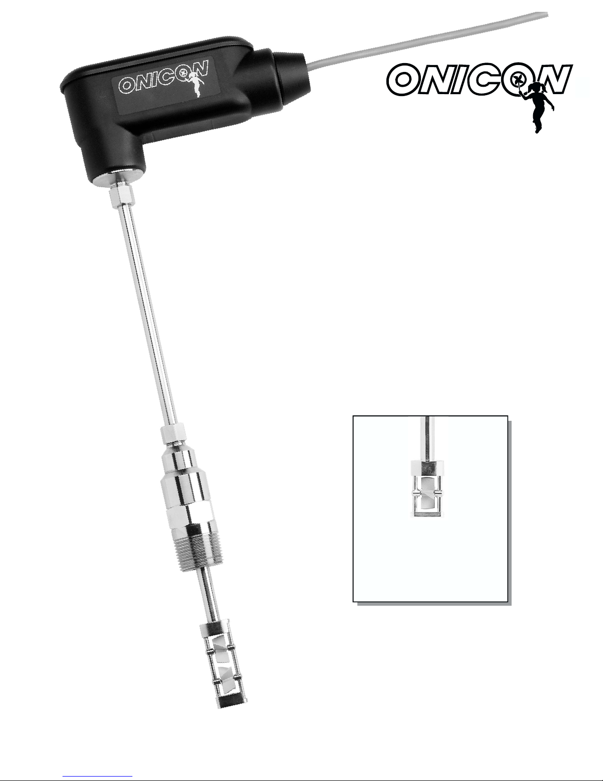
1.2 A TYPICAL INSERTION TURBINE FLOW METER
ONICON’s Insertion Turbine Flow Meters
measure the velocity of flowing liquids
by counting the frequency at which the
blades of a rotating turbine pass a fixed
electrode. Circuitry within the flow meter
electronics enclosure then converts the
rotational rate to digital and/or analog
signals which are transmitted via a
connecting cable to any of ONICON’s
display devices, BTU meters and/or a
data acquisition system.
Owner’s Manual for ONICON Insertion Turbine Flow Meters • September 27, 2001
3

1.3 STANDARD FEATURES AND SPECIFICATIONS
(Refer to specification sheet for particular model for additional details)
• F-1100 Series
Accuracy
± 0.5% OF READING at calibrated velocity
± 1% OF READING from 3 to 30 ft/s (10:1 range)
± 2% OF READING from 0.4 to 20 ft/s (50:1 range)
Sensing Method
Electronic impedance sensing (non magnetic and non-photoelectric)
Pipe Size Range
1¼” through 72” nominal
Supply Voltage
24±4 V AC/DC at 50 mA
Liquid Temperature Range
Standard: 180° F continuous, 200° F peak
High Temp: 280° F continuous, 300° F peak
Meters operating above 250° F require 316 stainless steel construction option
Ambient Temperature Range
-5 to 160° F (-20 to 70° C)
Operating Pressure
400 PSI maximum
Pressure Drop
Less than 1 PSI at 20 ft/s in 1½” pipe, decreasing in larger pipes and lower
velocities
Material
Wetted metal components
Standard: Electroless nickel plated brass
Optional: 316 stainless steel
Electronics Enclosure
Standard: Weathertight aluminum enclosure
Optional: Submersible enclosure
Electrical Connections
Standard: 10’ of cable with ½” NPT conduit connection
Optional: Indoor DIN connector with 10’ of plenum rated cable
Output Signal(s)
Standard: Calibrated frequency output (0-15v pulse)
Optional: Analog and Digital outputs also available, based on model
• F-1200 Series
This series has all of the features of the F-1100 series plus:
Dual Turbines and frequency output averaging circuitry to provide improved
Accuracy in short pipe runs.
Pipe size range is 2½” through 72” nominal
• FB-1200 Series
This series has all the features of the F-1200 series plus:
Capability of detecting and reporting flow direction
Owner’s Manual for ONICON Insertion Turbine Flow Meters • September 27, 2001
4

1.4 INSTALLATION HARDWARE
All ONICON insertion type meters can be installed and
removed via a 1” or larger full port ball valve without system
shutdown. The terms “Standard” and “Hot Tap” refer to the
installation method of the isolation valve kit only.
Standard Installation Hardware: For new construction or
scheduled shutdown. Once kit is installed, the flow meter can
be installed or removed without system shutdown.
Hot Tap Installation Hardware: For applications which
require the access hole in the pipe to be drilled through the
valve using a wet tap drilling machine, while the hydronic
system is pressurized and operating.
1.5 MODEL NUMBERING SYSTEM
F(B)-XX
SERIES OUTPUT SIGNAL
F-11 Single Turbine, Insertion Type
F-12 Dual Turbine, Insertion Type
FB-12 Bi-Directional, Insertion Type
F-13 Inline Turbine Meter
Example: “F-1210” = Dual turbine, analog output
YY
00 Frequency Output (15 V pulse)
For connection to Onicon display or BTU
meter only. Signal is too fast for most
building control systems (0-300 hz).
10 Analog Output (non-isolated)
Provides both 4-20 mA and 0-10 V
outputs. Most commonly used output
type. (3-wire connection)
11 Isolated Analog Output
Provides both 4-20 mA and 0-10 V
outputs. Signal ground is isolated from
power supply and pipe ground. (4-wire
connection)
20 Divided Output
(Solid state dry contact)
Provides an isolated binary/digital output.
Signal is divided to limit the maximum
frequency. For rate/totalization.
30 Scaled Output
(Solid state dry contact)
Provides an isolated binary/digital output
scaled to provide one pulse per desired
unit volume (i.e.: 1 pulse = 10 gal.).
Ideal for totalization applications.
Owner’s Manual for ONICON Insertion Turbine Flow Meters • September 27, 2001
5

1.6 WARRANTY AND SERIAL NUMBER
• Warranty
ONICON’s complete warranty is included in Appendix C of this manual as a part of the
“Conditions of Sale.” Meters purchased after November 1, 2000 include a two-year “No fault”
warranty which may cover accidental damage caused during installation or start up.
• Serial Number
The serial number of your Insertion Flow Meter is located on a label on the side of the
electronics enclosure. The model number is also listed on this label. The serial number is a
unique identifier that you should refer to, along with the model number, whenever you
require assistance regarding your meter.
Owner’s Manual for ONICON Insertion Turbine Flow Meters • September 27, 2001
6

SECTION 2.0: UNPACKING
Insertion Flow Meters are generally shipped in one package unless optional hardware or
equipment is ordered. This package may contain up to two complete meters along with the
optional installation kits. If any display equipment was ordered with the meters, the other
equipment will be packed separately. Please open all packages with caution to prevent
damage to their contents. In the event that they are damaged when you receive them, notify
the shipping company immediately and the ONICON Customer Service Department. All
products are shipped insured unless customer specifically requests otherwise.
2.1 CHECKING THAT YOU HAVE RECEIVED EVERYTHING
• The Documentation
Enclosed with each Insertion Flow Meter is a comprehensive documentation package
which includes the following items:
! OWNER’S MANUAL
! FLOW METER CALIBRATION DATA SHEETS
Please notify the ONICON customer service department if any of these documents are
missing.
• The Flow Meter
The flow meter is a rugged instrument and should arrive without any damage;
however, prior to installation, inspect it for physical damage such as broken turbine
blades or a damaged stem.
! Test the turbine(s) to see that they rotate freely when you blow on them
parallel to their shafts.
! Make sure that the threads on the hot tap adapter have not been damaged.
! Inspect the long stem for bends or other damage. The stem forms the seal
against liquid leakage as it slides through an ‘O’ ring outside the hot tap
adapter. Deep scratches may cause leakage.
! The serial and model numbers on the wire connection/calibration data tag
should match the numbers on the tag mounted directly on the flow meter. Be
sure that the unit was calibrated to the correct pipe size and flow range.
Owner’s Manual for ONICON Insertion Turbine Flow Meters • September 27, 2001
7

SECTION 3.0: INSTALLATION, REMOVAL & ADJUSTMENT
***CAUTION***
Insertion Flow Meters may often be installed in pipes which are under high
pressure. Accidents with these systems can cause serious injury or death. Only
!
3.1 SITE SELECTION
Install the flow meter where it will be accessible for personnel to perform necessary periodic
maintenance. The clearance required for installation is typically 30-36” from the pipe wall to
the nearest obstruction above the valve assembly. This clearance dimension will increase
with large diameter pipes. The environment should be free of corrosive liquids/fumes,
temperature extremes and heavy vibration. The following diagrams should be used as a guide
to the proper location for installing the meter.
persons experienced with high pressure systems and related knowledge in the
heating, cooling and fluid metering fields should attempt to install adjust or remove
the flow meter. Refer to the installation drawings before performing any work on
these meters.
ONICON will be happy to assist with technical recommendations and to provide
guidance by telephone and/or mail. On-site field engineering, installation and service
is also available at additional cost.
If yours is a single turbine meter and there is no suitable location, contact ONICON’s Sales
Office to discuss upgrading to a dual turbine meter. This meter is more tolerant of the
conditions that cause swirl, turbulence and flow profile distortions. Please make this decision
before installing the single turbine meter so that we may be able to give you credit if you elect
to upgrade to a dual turbine meter. Returns may be subject to a restocking charge.
Owner’s Manual for ONICON Insertion Turbine Flow Meters • September 27, 2001
8

Owner’s Manual for ONICON Insertion Turbine Flow Meters • September 27, 2001
9

3.2 MECHANICAL INSTALLATION
Turbine meters may require periodic maintenance and you should be able to remove the
meter when necessary without shutting down your system. To take advantage of the ONICON
Flow Meter’s built-in Hot Tap feature, it must be installed through an isolation valve. The
location must allow sufficient overhead clearance for meter removal (for cleaning and
preventative maintenance). A full 1” opening is required to clear the turbine assembly. Make
sure that your valves and fittings are full port and at least 1” in actual internal diameter. Also,
note that an oversized access hole can cause undesirable turbulence.
Try to limit the overall height from the pipe’s outside diameter to the top of the valve to 5½ 6”. ONICON calculates the stem length of the flow meter based on pipe size and this nominal
height. If your installation requires a taller fitting assembly and the dimension was not
specified on the order form, please contact the factory before installation. This way ONICON
can offer you credit for your meter if you decide to exchange it for one with a longer stem.
Returns may be subject to a restocking fee.
ONICON’s Standard Installation Hardware
kit is for use in a drained, non-pressurized
system. The access hole is drilled (1”
minimum) prior to installation of the 1”
NPT branch outlet, close nipple and full
port ball valve. Once the isolation valve is
installed, the piping system can be flushed
and pressurized. The flow meter may now
be inserted or removed by hand without
having to drain the system. Please read all
instructions before proceeding with meter
insertion.
ONICON’s Hot Tap Installation Hardware
kit offers an alternative installation when it
is not practical to drain or relieve the
pressure in the system. In this case, a 1¼”
branch outlet, close nipple and 1¼” full
port ball valve are installed first. Then, a
hot tap drilling apparatus can be used to
drill a 1” diameter hole through the valve,
without shutting down or draining the pipe.
Owner’s Manual for ONICON Insertion Turbine Flow Meters • September 27, 2001
10

When you are ready to refill the system, make sure that all lines are filled with
water before inserting the turbine into the stream. If the lines are not filled, air may
!
After fitting the necessary plumbing hardware, flush the
entire system so that it is free of flux, solder and slag. Prepare
to install the flow meter by loosening the clamping nut and
withdrawing the turbine assembly fully into the hot tap
adapter. Next, thread the adapter on to the ball valve using a
paste type thread sealant. Do not use Teflon tape because
torn strands of the tape may wind around the turbine,
slowing down or even stopping the turbine.
Check the installation for leaks by slightly opening the ball
valve under the hot tap adapter. An ‘O’ ring in the adapter
seals the meter stem against leakage. If there are any leaks
around the clamping nut or stem, DO NOT ATTEMPT TO
STOP THE LEAKAGE BY OVERTIGHTENING THE
CLAMPING NUT. Damage to this nut or the clamping ring
under the nut may prevent the assembly from properly holding the meter in the pipe. The
clamping nut is not part of the sealing mechanism. Any leaks in this area indicate that the ‘O’
ring is not sealing properly and you must contact the factory for assistance.
interrupt the flowing stream and damage the turbine assembly. A greater danger is
that if this is a hot water system, some water may flash into steam and exceed the
high temperature limit for the turbine and its mechanical assembly. This flash over
could exceed the pressure ratings of the meter and the assembly could fail allowing
steam and hot water to escape causing serious injury.
3.3 INSERTION OF THE METER
SYSTEM MAY BE UNDER HIGH PRESSURE. When adjusting the meter position or
!
Begin by calculating the effort that will be required to hold the meter. Establish adequate
footing for this task, taking extra caution when working from a ladder or platform. Use the
following formula:
E=0.11xP Where: E = effort in pounds
P = system pressure in pounds per square inch
removing it, be sure to hold the electronics enclosure firmly by hand before
SLOWLY loosening the positioning clamping nut. Failure to do this will allow the
pressure to suddenly and rapidly force the meter from the pipe causing serious
injury. The meter could also be damaged or break apart causing a break in the water
seal with the resultant loss of large amounts of water. The hand effort required to
hold the meter will be 0.11 times the pipe pressure.
Example: In a 300 PSI system, 33 pounds of effort is required to insert the meter into the pipe.
Owner’s Manual for ONICON Insertion Turbine Flow Meters • September 27, 2001
***CAUTION***
11
 Loading...