

Page 1
Flow and Energy Measurement
F-1000 SERIES
Turbine Flow Meter Conguration
Utility Installation and Operation Guide
ONICON
Page 2

TABLE OF CONTENTS
F-1000 SERIES TURBINE METER CONFIGURATION UTILITY AND INSTALLATION GUIDE
1.0 ACQUIRING, INSTALLING, AND UPDATING THE CONFIGURATION UTILITY ..................... 3
1.1 Acquiring the Conguration Utility ............................................................................................................. 3
1.2 Installing the Conguration Utility .............................................................................................................. 3
1.3 Updating the Conguration Utility .............................................................................................................5
2.0 USB CABLE AND DRIVER INSTALLATION ............................................................................... 6
2.1 Driver Installation ............................................................................................................................................... 6
2.2 USB Cable Connection to the Insertion Turbine Meter ......................................................................8
3.0 HOW TO USE THE CONFIGURATION UTILITY ........................................................................ 9
3.1 Opening the Software ...................................................................................................................................... 9
3.2 Connection, Status, and Mode Indicators ................................................................................................ 9
3.2.1 Connection Indicator .........................................................................................................................9
3.2.2 Status Indicator .................................................................................................................................10
3.2.3 Mode Indicator ..................................................................................................................................10
3.3 Programming/Informational Tabs .............................................................................................................11
3.3.1 Meter Data ..........................................................................................................................................11
3.3.2 Pipe Selection .....................................................................................................................................13
3.3.3 Flow Settings ......................................................................................................................................17
3.3.4 Frequency Output ............................................................................................................................19
3.3.5 Scaled Pulse Output ........................................................................................................................21
3.3.6 Turbine Rotation Test .....................................................................................................................22
3.3.7 Real Time Data ...................................................................................................................................25
3.3.8 Statistics ...............................................................................................................................................27
3.3.9 Status .....................................................................................................................................................29
3.3.10 Firmware Update ..............................................................................................................................31
ONICON Incorporated 727.447.6140 Page 2 onicon.com
Page 3

F-1000 SERIES TURBINE METER CONFIGURATION UTILITY AND INSTALLATION GUIDE
SECTION 1.0
ACQUIRING, INSTALLING, AND UPDATING THE CONFIGURATION UTILITY
1.1 ACQUIRING THE
CONFIGURATION UTILITY
1.2 INSTALLING THE
CONFIGURATION UTILITY
The ONICON Insertion Turbine Meter Conguration Utility was designed to
operate with the Windows XP, Windows 7, Windows 8, or Windows 10 operating
systems. The utility is available for download from ONICON’s website at
https://www.onicon.com/products/f1000-series-turbine-ow-meters.
Locate and open the folder which was downloaded. Within the folder, locate and
open the le named “TurbineMeter_Conguration_XXX_XXX_XXX.exe.” The
“XXX_XXX_XXX” in the le name will appear as numbers. The specic numbers
you see are based on the revision of the software provided by ONICON.
Once this .exe le is opened, please follow the on-screen prompts to complete
the installation of the program on your computer.
1. Click “Next” to continue the installation.
ONICON Incorporated 727.447.6140 Page 3 onicon.com
2. Accept the terms and click “Next” to accept the agreement.
Page 4

F-1000 SERIES TURBINE METER CONFIGURATION UTILITY AND INSTALLATION GUIDE
3. Complete the user information and click “Next.”
4. Select the installation location and click “Next.”
5. Click “Install” to proceed with the installation. The installation may take a
few minutes, and once complete, a new screen will appear.
ONICON Incorporated 727.447.6140 Page 4 onicon.com
Page 5

F-1000 SERIES TURBINE METER CONFIGURATION UTILITY AND INSTALLATION GUIDE
6. Click “Finish” to close the installation wizard.
You will now have an ONICON “Smart Turbine Meter” Icon on your
desktop which can be used to quickly open the utility. You can also
locate the conguration utility in the le location specied during
the installation process as shown in the installation sequence.
1.3 UPDATING THE
CONFIGURATION UTILITY
If at any point you wish to update the Conguration Utility to a newer version,
please use the following process.
1. Acquire the newest version of the software from ONICON - https://www.
onicon.com/products/f1000-series-turbine-ow-meters.
2. Uninstall any current versions of the Conguration Utility from your
computer. Use your computer’s Add/Remove Programs feature in the
Control Panel to remove the Congurator.
The software will be listed with the name “SmartTurbineMeter” and
Publisher “ONICON” in the program list.
3. Install the Conguration Utility per the procedure in the “Installing the
Conguration Utility” section above.
ONICON Incorporated 727.447.6140 Page 5 onicon.com
Page 6

F-1000 SERIES TURBINE METER CONFIGURATION UTILITY AND INSTALLATION GUIDE
SECTION 2.0.
DRIVER INSTALLATION AND USB CABLE
2.1 DRIVER INSTALLATION
At the end of the attempt to automatically install the driver, you will receive
either a “Successful” or “Unsuccessful” message. If you received a “Successful”
installation, you are ready to proceed to the next section of the manual, “How to
Use the Conguration Utility.”
If the automatic driver installation was “Unsuccessful”, the steps below outline the
procedure to manually install the driver for the turbine meter.
Open your Control Panel and access the Device Manager. Once in the Device
Manager, open the “Other devices” tree, right-click on the “Turbine Meter,” and
select “Update Driver Software…”:
In the “Update Driver Software” screen, click “Browse…” and select the folder for
the Conguration Tool which was provided by ONICON. Make sure the “Include
Subfolder” check box is enabled and click “Next”.
Driver Location
Selection
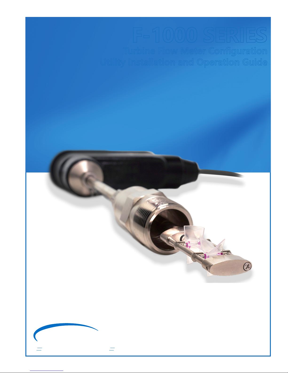
Once the location of the driver is specied, it will install. You will likely be asked
by Windows Security to accept the installation, which you must do in order to
proceed. Once the driver installation is complete, there will no longer be an error
under the Turbine Meter Device in the Device Manager:
ONICON Incorporated 727.447.6140 Page 6 onicon.com
Page 7
F-1000 SERIES TURBINE METER CONFIGURATION UTILITY AND INSTALLATION GUIDE
1. Driver Installing
2. Accept Installation
3. Driver Installation
Successful
4. “ONICON Smart
Turbine Meter” is
now installed and
assigned a COM
port number.
This completes the process to get your computer ready to run the Conguration
Utility and interface with the insertion turbine meter.
Please do not hesitate to contact ONICON Technical Support at 727-447-6140, or
email at service@onicon.com, if problems persist with the driver installation.
ONICON Incorporated 727.447.6140 Page 7 onicon.com
Page 8
F-1000 SERIES TURBINE METER CONFIGURATION UTILITY AND INSTALLATION GUIDE
2.2 USB CABLE CONNECTION
TO THE INSERTION
TURBINE METER
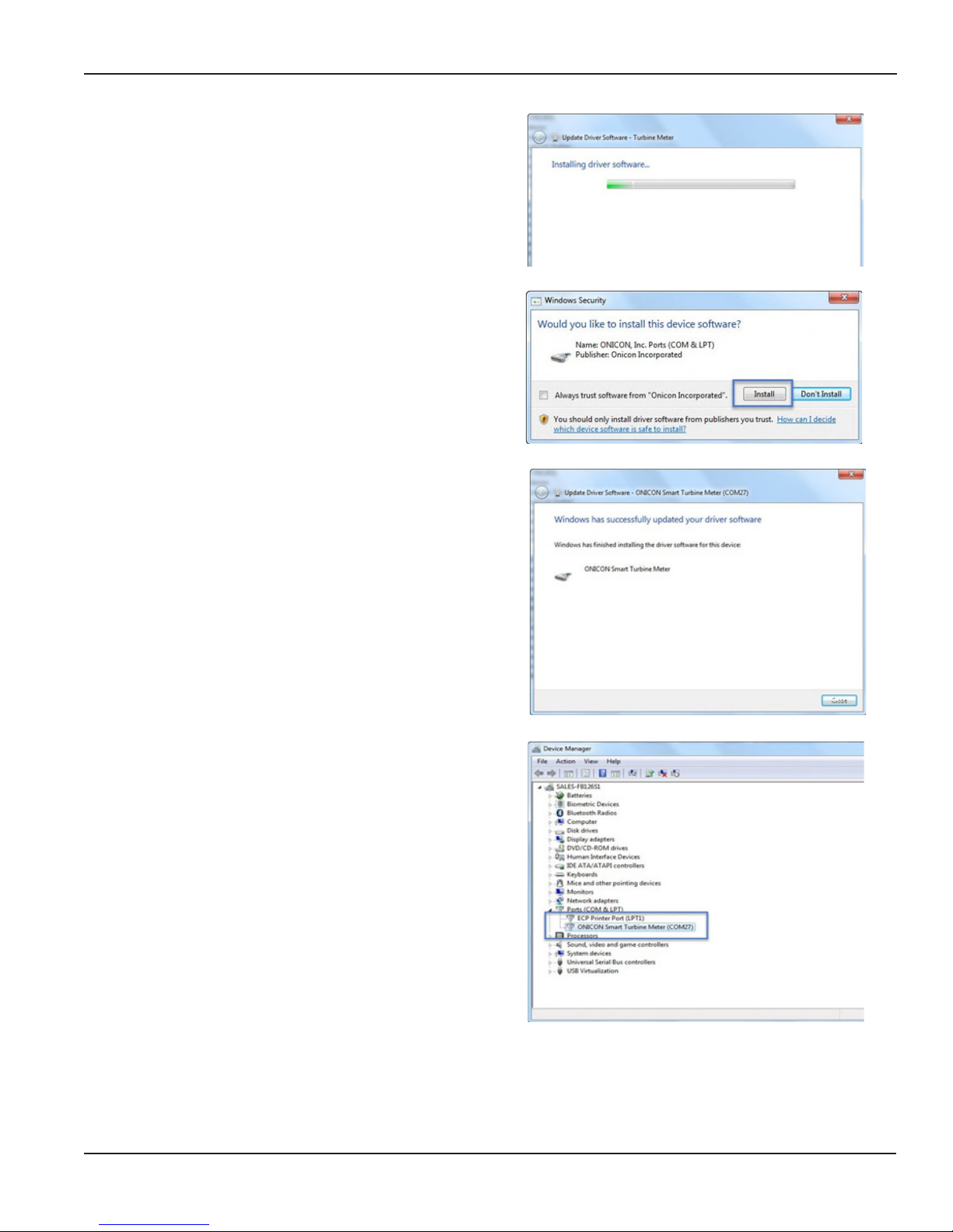
The physical interface to the insertion turbine meter is a USB Micro Type B Jack.
Most computers feature one or more USB Type A Jacks. If your computer has
a USB Type A Jack, utilize an “A Male to Micro B Male” cable to connect to the
meter.
A Male to Micro B Male USB Cable
The maximum allowable USB cable length, before a powered hub or extender
would need to be utilized, is 5 meters, or 16 feet 5 inches.
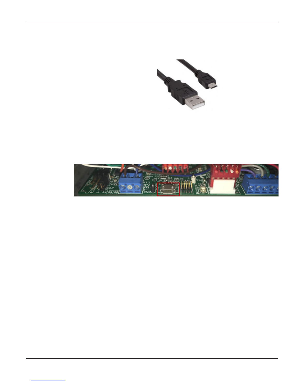
The USB Micro connection is made at the female connector inside the meter’s
electronics enclosure.
WARNING
The micro USB connection inside the turbine meter enclosure can be easily
damaged if the cable is not plugged straight into the connector – such that
a moment force is applied to the connector. Please be sure the cable is only
pushed straight in or pulled straight out.
ONICON Incorporated 727.447.6140 Page 8 onicon.com
Page 9

F-1000 SERIES TURBINE METER CONFIGURATION UTILITY AND INSTALLATION GUIDE
SECTION 3.0.
HOW TO USE THE CONFIGURATION UTILITY
3.1 OPENING THE SOFTWARE
Open the “Smart Turbine Meter” software by double-clicking the logo on your
computer’s desktop or through the .exe located in the folder the program was
installed in earlier.
The “ONICON FLOW AND ENERGY MEASUREMENT” splash screen will appear
followed by the Conguration Utility opening on the Meter Data tab.
3.2 CONNECTION, STATUS, AND
MODE INDICATORS
First screen which appears after opening the Congurator
Three indicators are available on the top portion of the congurator window.
Their color and text will change depending on the current operating status of the
meter.
A QR code is also available which will link your cellphone to ONICON’s website
3.2.1 CONNECTION INDICATOR
This indicator provides information about the current status of the hardware
connection to the turbine meter. Three variations exist.
“Connected” text with green background
This status is telling the user that the meter is connected and
there are no errors.
“Initializing” text with yellow background
This status appears when the USB cable is re-connected after
being disconnected. Once the initialization process ends,
either a “connected” or “missing” status will appear.
ONICON Incorporated 727.447.6140 Page 9 onicon.com
Page 10

F-1000 SERIES TURBINE METER CONFIGURATION UTILITY AND INSTALLATION GUIDE
“Missing” text with red background
This status appears when the USB cable to the turbine meter
is disconnected. If the cable is connected and the fault is
still present, check the Device Manager as explained in the
“Driver Installation” section, and make sure there is no error
with the port used for the turbine meter connection. Reinstall the driver if there is a fault.
If there is no error with the port in the Device Manager, close the Conguration
Utility, remove and re- install the USB cable, and then re-open the Conguration
Utility. The meter should initialize and connect normally.
3.2.2 STATUS INDICATOR
This indicator provides information about the current status of the alarms and
warnings in the “Status” tab.
“Normal” text with green background
This status indicates that the meter does not have any
warnings or alarms.
“ALARM” text with ashing orange background
This status indicates that an alarm is present on the meter. If
you open the “Status” tab, you will nd a complete list of the
current alarms.
“Warning” text with ashing yellow background
This status indicates that a warning is present on the meter. If
you open the “Status” tab, you will nd a complete list of the
current warnings.
More information about the dierent warnings and their meanings can be found
in the “Status” section on pages 30-32.
3.2.3 MODE INDICATOR
The mode indicator noties the user if the meter is in
“Running” mode or “Calibration” mode. “Calibration” mode
is only used by ONICON during a factory calibration. If you
receive a meter which states the mode is “Calibration,” please
contact ONICON immediately.
ONICON Incorporated 727.447.6140 Page 10 onicon.com
Page 11

F-1000 SERIES TURBINE METER CONFIGURATION UTILITY AND INSTALLATION GUIDE
3.3 PROGRAMMING/
INFORMATIONAL TABS
The various diagnostic information and conguration options available with the
Congurator Utility are separated into dierent sections called tabs. Each tab has
a dierent purpose. For example, the “Pipe Selection” tab allows the user to set
the pipe size and material that the meter’s output is congured for. The “Realtime Data” tab allows the user to see the current status of the turbine rotation as
well as the output signals.
Each tab and the information available within each tab are discussed in the
following sections.
3.3.1 METER DATA
The meter data tab provides general information about the meter like its
serial number, manufactured/calibrated date, meter type, and date it was last
programmed.
Meter Data Tab
Serial Number (Read Only)
The serial number of the meter is a unique identier. When contacting ONICON
for support or additional questions regarding a meter, please be ready to provide
this serial number. If your meter shipped calibrated to a specic pipe size and
output range, ONICON can retrieve this original calibration data with the help of
the serial number.
Manufacture Date (Read Only)
The date that your meter was manufactured at ONICON. This date may not match
the calibration date if the meter has been returned to ONICON for recalibration
service after the original manufacture date.
Calibration Date (Read Only)
Date that your meter was last calibrated at ONICON. This date may not match
the manufacture date if the meter has been returned to ONICON for recalibration
service after the original manufacture date.
ONICON Incorporated 727.447.6140 Page 11 onicon.com
Page 12

F-1000 SERIES TURBINE METER CONFIGURATION UTILITY AND INSTALLATION GUIDE
Application Version Number (Read Only)
This is the version number of the ONICON Conguration Utility. This number is
also available in the program window. ONICON may ask for this number if you
are experiencing problems with the utility.
Bootloader Version Number (Read Only)
This is the version number of the ONICON Insertion Turbine Meter rmware. This
number is also available on the window of the program. ONICON may ask for this
number if you are experiencing problems with the utility or turbine meter.
Meter Type (Read Only)
The meter type denes the number of turbines and whether your meter is an
insertion/inline type.
• F-1100 – Single Turbine Insertion Flow Meter
• F-1200 – Dual Turbine Insertion Flow Meter
• F-1101 and F-1134 – Single Turbine Inline Flow Meter
The number of turbines and the body type directly aect the calibration, and
whether the pipe data needs to be entered. For these reasons, the meter type is
set at the factory and is read-only.
Relay Output Conguration (Editable)
The relay output can be congured as:
• Not Used – Select this option if you do not want to use the scaled or alarm
output.
• Scaled Pulsed Output – Select this option if you want to congure the relay
output as a pulse output for volume totalization
(Example: 1 pulse = 10 gallons).
• Alarm Output – Select this option if you want to congure the relay output
as an alarm contact. The relay contact changes state depending on the
alarm status. The alarm status is indicated near the top of the Congurator’s
window, or also viewable on the “Status” tab. An alarm output causes the
relay contact to close. No alarm causes the alarm contact to be open.
Meter Length (Read Only)
The meter length is the distance between the bottom of the meter’s black
electronics enclosure and the end of the meter. This distance is used in the
calculation of the insertion depth in the “Pipe Selection” tab. This length is invalid
when the meter type is set for “F-1101 and F-1134.”
ONICON Incorporated 727.447.6140 Page 12 onicon.com
Meter Factor (Read Only)
The meter factor has units of pulses per gallon and is the response characteristic
of the turbine(s). This value is measured when the meter is wet calibrated at
ONICON.
Page 13

F-1000 SERIES TURBINE METER CONFIGURATION UTILITY AND INSTALLATION GUIDE
Program Date (Read Only)
This is the date the meter was last modied via the Conguration Utility.
3.3.2 PIPE SELECTION
The pipe selection tab provides the means to modify the pipe size and material
the output of the turbine meter will be scaled to.
The accuracy of the volumetric output, whether it is volume rate (4-20mA)
or volume total (scaled pulse), is dependent on an accurate pipe ID being
programmed in the meter:
Volumetric Flow Output=Average Velocity x Internal Pipe Area
Pipe Selection Tab
Meter Type (Read Only)
The meter type denes the number of turbines and whether your meter is an
insertion/inline type.
• F-1100 – Single Turbine Insertion Flow Meter
• F-1200 – Dual Turbine Insertion Flow Meter
• F-1101 and F-1134 – Single Turbine Inline Flow Meter
The number of turbines and the body type directly aect the calibration, and
whether the pipe data needs to be entered. For these reasons, the meter type is
set at the factory and is read-only.
If “F-1101 and F-1134” is the meter type, then there will be no further information
within the Pipe Selection tab.
ONICON Incorporated 727.447.6140 Page 13 onicon.com
Page 14

F-1000 SERIES TURBINE METER CONFIGURATION UTILITY AND INSTALLATION GUIDE
Pipe Size Programming Method (Editable)
The programming method denes how the pipe information is input by the user.
Two options are available:
• Table – The application pipe ID, OD, and remaining stem is automatically
calculated based on the pipe material, size, and schedule selected from the
table on this page.
IMPORTANT
The “SET” button must be pressed after selecting “Table”.
Location of “Set” button
To select a pipe size from the table, open the tree to the specic pipe
material, schedule, and size that your meter will be installed in. Click on that
pipe size, and then press the “Select Standard Pipe” button.
Once you select the pipe size, the ID, OD, remaining stem lengths, and
gauge length will auto-ll with the correct dimensions. The white box above
the “Select Standard Pipe” button will auto-ll with the description of the
selected pipe:
#1 Select Pipe
#2 Press Button
Selecting pipe size and conrming via “Select Standard Pipe” button
ONICON Incorporated 727.447.6140 Page 14 onicon.com
Page 15

F-1000 SERIES TURBINE METER CONFIGURATION UTILITY AND INSTALLATION GUIDE
• Custom – By selecting custom, two new windows will appear which allow
the user to manually enter a pipe ID and pipe OD. A warning status will be
triggered if the ID > OD. The units of measurement for the ID and OD are
inches.
Like it was for a table entry of the pipe size, the remaining stem dimensions
as well as the gauge length will auto-ll after the ID and OD have been
congured.
Location of “Set” buttons for Pipe ID and Pipe OD.
IMPORTANT
The “SET” button must be pressed after entering a pipe ID and OD.
Meter Length (Read Only)
The meter length is the distance between the bottom of the meter’s black
electronics enclosure and the end of the meter. This distance is used in the
calculation of the insertion depth in the “Pipe Selection” tab.
Remaining Stem Length with Installation Hardware (Read Only)
This length is a calculated value of how much insert-able length a meter has left,
based on the calculated Gauge Length (proper insertion depth). The remaining
stem is a function of the meter length, the pipe ID and OD, and the type of
installation kit.
• The “Dry Tap Kit” is a ball valve assembly designed to be installed during
new construction or when the pipe was drained. An example of a “dry tap
kit” is an ONICON INSTL0001-FMD for carbon steel pipe. The valve assembly
height assumed for this calculation is 5.5 inches.
IMPORTANT
This calculated remaining stem should always be a positive value. If it is
negative, that means the meter cannot reach the proper insertion depth with
a valve assembly that is 5.5” or taller. If the value is negative, the eld will
be highlighted yellow, warning you of this.
If you have provided your own valve assembly, calculate the remaining stem with
the following equation:
ONICON Incorporated 727.447.6140 Page 15 onicon.com
Customer Remaining Stem =
Remaining Stem with Dry Tap Kit - (Customer Valve Assembly Height-5.5)
Page 16

F-1000 SERIES TURBINE METER CONFIGURATION UTILITY AND INSTALLATION GUIDE
• The “Hot Tap Kit” is a ball valve assembly designed to be installed after the
pipe was lled, allowing a wet tap drill to cut the pipe without draining it
rst. An example is an ONICON INSTL0002-FMH for carbon steel pipe. The
valve assembly height assumed for this calculation is 6.875.
IMPORTANT
This calculated remaining stem should always be positive. If it is negative,
then that means that the meter cannot reach the proper insertion depth with
a valve assembly that is 6.875” or taller. If the value is negative, the eld
will be highlighted yellow, warning you of this.
If you have provided your own valve assembly, calculate the remaining stem with
the following equation:
Customer Remaining Stem =
Remaining Stem with Hot Tap Kit-(Customer Valve Assembly Height-6.875)
The customer valve assembly height is the distance from the outside of the pipe
to the top of the 1” outlet that the meter is inserted through:
ONICON Incorporated 727.447.6140 Page 16 onicon.com
Valve assembly height “Required Dimension” from above
Gauge Length (Read Only)
The gauge length is a calculated value, based on the meter length, pipe ID, and
pipe OD. It provides the user with the dimension needed to correctly set the
insertion depth of the meter for a specic meter length and pipe size.
Page 17

F-1000 SERIES TURBINE METER CONFIGURATION UTILITY AND INSTALLATION GUIDE
When inserting the meter into the pipe, push the meter in until the distance from
the pipe wall to the bottom of the meter’s black electronics enclosure matches
the gauge length:
3.3.3 FLOW SETTINGS
The ow settings tab contains conguration parameters which allow the user
to set the ow rate and scaled output units, analog output scale, and meter
damping.
ONICON Incorporated 727.447.6140 Page 17 onicon.com
Flow Setting Tab
Full Scale Flow Rate in Volume Rate Units (Editable)
This parameter sets the value for the 20mA/10V/5V analog output full scale, if the
meter has an analog output. The units of measurement will match that set in the
“Volume Rate Units” parameter also on this tab.
After entering the value on this page, press the “Set” button to permanently
program the meter with this output scale.
ONICON recommends that the analog output range is set to 1.25 times larger
than the maximum realistic ow rate which could occur in the system.
Page 18

F-1000 SERIES TURBINE METER CONFIGURATION UTILITY AND INSTALLATION GUIDE
Full Scale Flow Rate gpm (Read Only)
This parameter shows the gpm equivalent of the “Full Scale Flow Rate in Volume
Rate Units.” If the units of measurement for both parameters is gpm, then they
will be identical.
Volume Rate Units (Editable)
This parameter allows the user to set the units of measurement for the analog
output, if the meter has one.
After selecting the desired units, press the “Set” button to permanently program
the meter with these ow rate units.
There are also three selections for custom units of measurement. If one of these
selections in made, the “Flow Settings” tab will populate with two new functions
described below.
Full Scale Flow Rate User Volume Units (Read Only or Editable)
If you have already selected volume rate units which weren’t “user dened,”
then this parameter will not be editable. If “user dened” volume rate units were
selected, this parameter is used to describe the units of measurement you will be
using.
In the example below, “5 Gal Bucket per Hour” was the entered unit. Press “Set”
after entering your description to permanently set this value:
Flow Rate User Volume Units Conv Factor (Read Only or Editable)
If you have selected volume rate units which weren’t “user dened,” then this
parameter will not be editable. If “user dened” volume rate units were selected,
this parameter is used to describe conversion factor between gpm and your
custom unit of measurement.
In the example below, the user dened volume rate had a per hour time frame.
The conversion factor was set to 500. The full-scale ow rate in user units was set
to 5,000,000. The number is converted to gpm as follows:
ONICON Incorporated 727.447.6140 Page 18 onicon.com
Full Scale Equivalent (gpm) =
Full Scale in Dened (units per hour)
60 x Conversion Factor
Page 19

F-1000 SERIES TURBINE METER CONFIGURATION UTILITY AND INSTALLATION GUIDE
For user dened units per minute and per second:
Full Scale Equivalent (gpm) =
Full Scale Equivalent (gpm) =
Full Scale in User Dened (units per minute)
Conversion Factor
60 x Full Scale in User Dened (units per second)
Conversion Factor
Scaled Pulse Output Units (Editable)
This parameter sets the units of measurement for the scaled output (volume
totalization pulse). If “user dened unit” was selected, the scaled output will
be subject to the same conversion factor programmed at the “Flow Rate User
Volume Units Conv Factor” parameter.
After selecting the scaled pulse units, press the “Set” button to accept the change.
Time Constant Damping Level (Editable)
This parameter sets the damping level on the meter’s analog output. The
damping is an algorithm used to smooth the response of the meter’s analog
output over a period of time. The default is 5 seconds. The allowable range is 1 to
60 seconds. ONICON recommends leaving this value at the default value of 5.
If you change this value, press the “Set” button to accept the change.
3.3.4 FREQUENCY OUTPUT
This tab allows the user to change the settings associated with the frequency
output on the turbine meter. The frequency output is available on every version
of the turbine meter. The frequency output is typically only used with an ONICON
display or BTU meter as a digital input for ow rate and totalization, but it can
also be used for diagnostics by measuring the speed (Hz) of the output with a
multimeter.
Full Scale Frequency Output Pulses Per Second (Editable)
This parameter sets full scale Hz on the frequency output. The full scale in Hz will
match the full scale volume rate.
Example: Setting the full-scale frequency to 200 Hz will cause the meter to output
200 Hz on the frequency output if the ow meter is measuring ow equal to full
scale ow rate in the “Flow Settings” tab.
Full Scale Flow Rate <units> (Read Only)
This parameter is a duplicate of the “Full Scale Flow Rate in Volume Rate Units”
parameter from the “Flow Settings” tab. It is meant to show you what is already
programmed in the meter, as a reference, so that you don’t need to return to the
“Flow Settings” tab to remind yourself of the setting.
The <units> will populate with whatever ow rate unit was selected on the “Flow
Settings” tab.
ONICON Incorporated 727.447.6140 Page 19 onicon.com
Page 20

F-1000 SERIES TURBINE METER CONFIGURATION UTILITY AND INSTALLATION GUIDE
Full Scale Flow Rate gpm (Read Only)
This parameter is a duplicate of the “Full Scale Flow Rate gpm” parameter from
the “Flow Settings” tab. It is meant to show you what is already programmed in
the meter, as a reference, so that you don’t need to return to the “Flow Settings”
tab to remind yourself of the setting.
Scaled Frequency Factor pulses / <units> (Read Only)
This parameter is a calculated value, and it provides the scaling factor for
measuring the volume rate from the turbine meter’s frequency output. The
<units> was selected in the “Flow Settings” tab. If custom units were selected,
the conversion factor was already taken into account when the scale factor was
calculated.
How to calculate ow rate from the frequency output scale factor:
Measured Flow Rate (Volume/Minute) =
Measured Flow Rate (Volume/Second) =
Measured Flow Rate (Volume/Hour) =
Measured Hz x 60
Scaled Frequency Factor
Measured Hz
Scaled Frequency Factor
Measured Hz x 3600
Scaled Frequency Factor
Scaled Frequency Factor pulses / gallon (Read Only)
This parameter is a calculated value, and it provides the scaling factor for
measuring the volume rate from the turbine meter’s frequency output. The units
of measurement are pulses per gallon (ppg). If gpm units were selected in the
“Flow Settings” tab, this value will be a duplicate of the previous parameter.
How to calculate ow rate from the frequency output scale factor in ppg:
Measured Flow Rate (Gallon/Minute) =
Measured Flow Rate (Gallon/Second) =
Measured Flow Rate (Gallon/Hour) =
Scaled Frequency Factor (ppg)
Measured Hz x 60
Scaled Frequency Factor (ppg)
Measured Hz
Scaled Frequency Factor (ppg)
Measured Hz x 3600
ONICON Incorporated 727.447.6140 Page 20 onicon.com
The ppg value is referred to as the “Meter Factor” and is a very important value
when the turbine meter is used along with a System-10 BTU meter, System-20
BTU meter or D-100/D-1200 ow display. When programming one of these
peripherals to be used with an Insertion Turbine Meter, you must be prepared
to enter this value so that the BTU Meter/Display can properly convert frequency
pulses to ow rate and volume.
Page 21

F-1000 SERIES TURBINE METER CONFIGURATION UTILITY AND INSTALLATION GUIDE
3.3.5 SCALED PULSE OUTPUT
The scaled pulse output tab provides parameters for conguring the units of
measurement and scaling of the relay output. The relay output is available on all
versions of the Insertion Turbine Meter. The “Relay Output Conguration” in the
“Meter Data” tab must be congured as a “Scaled Pulse Output” for this tab to be
visible.
Scaled Pulse Output tab
Scaled Pulse Output Units (Editable)
This parameter allows the user to set the units of measurement for the scaled
output. This parameter is a duplicate of the parameter with the same name in the
“Flow Settings” tab.
After selecting the units of measurement, press the “Set” button to accept your
changes.
Scaled Output Multiplier (Editable)
This parameter allows the user to set the volume that each pulse is worth. The
available selections are:
1, 10, 100, 1000, or 10000 units of volume per pulse.
Press the “Set” button to accept any changes which are made.
The pulse volume along with the pulse duration determine when the meter
will enter a “pule overrun” alarm. A pulse overrun occurs when the meter is
attempting to provide a scaled pulse faster than the duration allows. Please
follow the on-screen instructions for determining if your pulse scaling and
duration settings could cause a pulse overrun.
ONICON Incorporated 727.447.6140 Page 21 onicon.com
Page 22

F-1000 SERIES TURBINE METER CONFIGURATION UTILITY AND INSTALLATION GUIDE
Scaled Output Pulse Duration (Editable)
This parameter congures the pulse duration, or the time that the relay output of
the meter is in a closed state, when the scaled pulse output occurs.
There are four settings available:
• “50 ms on 1 s total” – When a scaled pulse occurs, the duration on the
relay closure will be 50ms. A scaled pulse cannot occur more than once per
second (1 Hz).
• “100 ms on 1 s total” –When a scaled pulse occurs, the duration on the relay
closure will be 100ms. A scaled pulse cannot occur more than once per
second (1 Hz).
• “500 ms on 2 s total” –When a scaled pulse occurs, the duration on the relay
closure will be 500ms. A scaled pulse cannot occur more than once per 2
seconds (1/2 Hz).
• “1000ms on 3s total” – When a scaled pulse occurs, the duration on the relay
closure will be 1000ms (1 second). A scaled pulse cannot occur more than
once per 3 seconds (1/3 Hz).
The pulse volume along with the pulse duration determine when the meter
will enter a “pule overrun” alarm. A pulse overrun occurs when the meter is
attempting to provide a scaled pulse faster than the duration allows. Please
follow the on-screen instructions for determining if your pulse scaling and
duration settings could cause a pulse overrun.
3.3.6 TURBINE ROTATION TEST
The turbine rotation test tab allows the user to congure the settings which
control the rotation test alarm output. The turbine rotation test is only used with
dual turbine meters. Its function is to detect if the top and bottom turbines are
not spinning at similar speeds, which would indicate possible damage or debris
in the turbines. The meter can be set to continue operate normally if there’s an
alarm or stop producing an output signal in addition to supplying an alarm to the
Conguration Utility. Also, the relay output on the meter can be set to change
state if an alarm was present. To enable the relay to close when there is an alarm,
enable this feature in the “Meter Data” tab.
ONICON Incorporated 727.447.6140 Page 22 onicon.com
Page 23

F-1000 SERIES TURBINE METER CONFIGURATION UTILITY AND INSTALLATION GUIDE
If this alarm is enabled and present on your meter, check the “Real-time Data” tab
to determine which turbine is not spinning as fast as the other. Then, the meter
should be removed, and the turbines should be inspected for damage or debris.
Be sure the meter is installed at the correct depth and orientation if this alarm is
present at initial installation.
Turbine Rotation Test tab
Turbine Rotation Test (Editable)
This parameter denes if the turbine rotation test is active, and what happens to
the operation of the meter if the test determines a problem with the turbines. The
Congurator provides the following options:
• O – The turbine rotation test is disabled.
• Alarm and Run – The turbine rotation test will be active in the background. If
a problem is detected, the relay output will close (if activated in the “Meter
Data” tab) and an alarm will be present in the “Status” tab. The meter will
continue to provide a frequency, scaled, and analog output even though it is
likely inaccurate because of a turbine problem.
• Alarm and Zero Flow - The turbine rotation test will be active in the
background. If a problem is detected, the relay output will close (if activated
in the “Meter Data” tab) and an alarm will be present in the “Status” tab. The
meter will cease providing a ow rate signal on the frequency, scaled, and
analog outputs.
After changing this setting, press the “Set” button to accept the change.
ONICON Incorporated 727.447.6140 Page 23 onicon.com
Turbine Rotation Test enable/disable options.
Page 24

F-1000 SERIES TURBINE METER CONFIGURATION UTILITY AND INSTALLATION GUIDE
Turbine Rotation Allowed Percent Dierence (Editable)
This parameter sets the allowed dierence in turbine rotation speed before an
alarm is enabled. The default value is 55.
Example with “Allowed Percent Dierence” set at 55:
• The “Status” tab reports that the top turbine frequency is 60 Hz, while
the bottom turbine is 40 Hz. The percent dierence in rotation is 33.33%.
Turbine rotation alarm is not triggered.
• The “Status” tab reports that the top turbine frequency is 60 Hz, while
the bottom turbine is 25 Hz. The percent dierence in rotation is 58.33%.
Turbine rotation alarm has the potential to be triggered (See “Turbine
Rotation Detect Time Sec” below).
After the parameter is changed, press “Set” to conrm the changes.
Turbine Rotation Detect Time Sec (Editable)
This parameter set the amount of time that the percent dierence in turbine
rotation must occur before an alarm is triggered. The default value is 120 sec.
This gives the meter a buer, before going into alarm, in case debris stopped the
turbine momentarily.
Example with “Allowed Percent Dierence” set at 55 and “Turbine Rotation
Detect Time Sec” set at 120:
The “Status” tab reports that the top turbine frequency is 60 Hz, while the
bottom turbine is 25 Hz. The percent dierence in rotation is 58.33%. Turbine
rotation alarm will be triggered after 120 seconds with the meter in this
state. If the turbine rotation % dierence falls below 55 before 120 seconds is
reached, the 120 second counter will reset, and no alarm will trigger.
After the parameter is changed, press “Set” to conrm the changes.
Turbine Rotation Reset Time Sec (Editable)
This parameter sets the time required for the turbine rotation alarm to disable
after a turbine rotation alarm has already been enabled. The default time is 10
seconds.
After the parameter is changed, press “Set” to conrm the changes.
ONICON Incorporated 727.447.6140 Page 24 onicon.com
Page 25

F-1000 SERIES TURBINE METER CONFIGURATION UTILITY AND INSTALLATION GUIDE
3.3.7 REAL TIME DATA
The real time data tab displays data related to the meter’s operation. The
turbine speeds, output levels, and equivalent ow speed based on pipe size
conguration.
The information on this tab is used to diagnose a turbine which is not spinning,
and to provide a ow rate reading without having to measure an output signal
level on the meter’s wires with a multimeter.
Real-time Data tab
Average Pulses Per Second (Read Only)
This parameter reports the average turbine signal pulses per second (Hz). The
average is the mean of the top and bottom turbine signal pulses per second.
Top Pulses Per Second (Read Only)
This parameter reports the top turbine signal pulses per second (Hz).
If the bottom turbine reports a Hz value, yet the top shows none, the turbine
meter should be inspected for debris or damage.
Bottom Pulses Per Second (Read Only)
This parameter reports the bottom turbine signal pulses per second (Hz).
If the top turbine reports a Hz value, yet the top shows none, the turbine meter
should be inspected for debris or damage.
Instantaneous Input Frequency Hz (Read Only)
This frequency is an un-scaled output and requires the meter’s “Meter Factor”
from the “Meter Data” tab in order to be converted to gpm.
ONICON Incorporated 727.447.6140 Page 25 onicon.com
Page 26

F-1000 SERIES TURBINE METER CONFIGURATION UTILITY AND INSTALLATION GUIDE
Damped Input Frequency Hz (Read Only)
Identical to the instantaneous frequency, but after the damping level has been
applied. The damping is congured in the “Flow Settings” tab.
Output Frequency Hz (Read Only)
This is the scaled frequency output available on the meter’s green wire referenced
to common (black). The output is scaled based on the Pipe ID and Pipe OD
congured in the “Pipe Selection” tab.
Base Flow Rate gps (Read Only)
This value shows the ow rate in gallons per second. This is the ow rate of the
meter based on the pipe ID programmed in the “Pipe Selection” tab.
Base Flow Rate gpm (Read Only)
This value shows the ow rate in gallons per minute. This is the ow rate of the
meter based on the pipe ID programmed in the “Pipe Selection” tab.
Application Flow Rate <units/minute> (Read Only)
This value shows the ow rate in the user’s designated volume unit per minute.
This is the ow rate of the meter based on the pipe ID programmed in the “Pipe
Selection” tab. If the meter is connected directly to a BMS via the analog output,
or connected to an ONICON display or BTU meter, it should be veried that the
reading in this parameter matches the BMS/ ONICON display or BTU meter. It
should also, be conrmed that the units of measurement match between turbine
meter and BMS/ONICON display or BTU meter.
Local Velocity fps (Read Only)
Shows the ow velocity, in feet per second, that the average turbine pulses is
equivalent to based on the pipe ID congured in the “Pipe Selection” tab. This
velocity is not corrected for the amount of pipe area the turbine meter acquires
from being inserted in the pipe.
Pipe Velocity fps (Read Only)
Shows the ow velocity, in feet per second, that the average turbine pulses is
equivalent to based on the pipe ID congured in the “Pipe Selection” tab. This
velocity is also corrected for the amount of pipe area the turbine meter acquires
from being inserted in the pipe to the “Gauge Length” position.
ONICON Incorporated 727.447.6140 Page 26 onicon.com
Page 27

F-1000 SERIES TURBINE METER CONFIGURATION UTILITY AND INSTALLATION GUIDE
3.3.8 STATISTICS
The statistics tab provides some of the data already appearing in the “Real-time
Data” tab, and in addition provides historical information about the meter’s
operation.
Statistics tab
Flow Velocity fps (Read Only)
Shows the ow velocity, in feet per second, that the average turbine pulses is
equivalent to based on the pipe ID congured in the “Pipe Selection” tab. This
velocity is corrected for the amount of pipe area the turbine meter acquires
from being inserted in the pipe to the “Gauge Length” position. Therefore, it is
equivalent to the Pipe Velocity fps in the Real-time Data tab.
Total Scaled Pulses (Read Only)
This value shows the number of scaled pulses produced by the meter since
operation.
This value is useful for troubleshooting the scaled output on the meter. If
your BMS is not recording pulses, it should be veried that this value is not
incrementing. If it is incrementing, then the problem lies in the wire connection,
or the conguration of the BMS input. This value can only be reset at the
ONICON factory during recalibration service.
Total Gallons (Read Only)
This value shows the number of gallons measured by the meter since operation.
ONICON Incorporated 727.447.6140 Page 27 onicon.com
Page 28

F-1000 SERIES TURBINE METER CONFIGURATION UTILITY AND INSTALLATION GUIDE
User Dened Volume Total gallon (Resettable)
This value provides a user-resettable totalizer built-in the turbine ow meter.
By resetting the value to zero, and then verifying the reading after X minutes,
this value can be used as a means to compare the ow meter’s actual volume
measurement over X period of time to a volume measurement acquired through
the use of a BMS connected to the scaled output, or the volume reported by a
local ONICON display or BTU meter.
Run Seconds (Read Only)
This value displays the length of the time the meter has been operational in
seconds.
Run Hours (Read Only)
This value displays the length of time the meter has been operational in hours.
Average Pulses Per Second (Read Only)
This parameter reports the average turbine signal pulses per second (Hz). The
average is the mean of the top and bottom turbine signal pulses per second.
Top Pulses Per Second (Read Only)
This parameter reports the top turbine signal pulses per second (Hz).
If the bottom turbine reports a Hz value, yet the top shows none, the turbine
meter should be inspected for debris or damage.
Bottom Pulses Per Second (Read Only)
This parameter reports the bottom turbine signal pulses per second (Hz).
If the top turbine reports a Hz value, yet the top shows none, the turbine meter
should be inspected for debris or damage.
Total Average Turbine Pulses (Read Only)
This value displays the total number of average turbine pulses measured
since the turbine meter has been operational. The average turbine pulses is
approximately equal to the mathematical mean of the top and bottom turbine
pulse count.
Total Top Turbine Pulses (Read Only)
ONICON Incorporated 727.447.6140 Page 28 onicon.com
This value displays the total number of top turbine pulses measured since the
meter has been operational. A top turbine pulse occurs when a blade of the top
turbine passes the top electrode while the meter is submerged in a conductive
medium.
Page 29

F-1000 SERIES TURBINE METER CONFIGURATION UTILITY AND INSTALLATION GUIDE
Total Bottom Turbine Pulses (Read Only)
This value displays the total number of bottom turbine pulses measured since the
meter has been operational. A bottom turbine pulse occurs when a blade of the
bottom turbine passes the bottom electrode while the meter is submerged in a
conductive medium.
Peak Average Turbine Pulses (Read Only)
This value displays the largest average turbine pulse speed (Hz) measured by the
turbine meter at any point during its operation.
Peak Top Turbine Pulses (Read Only)
This value displays the largest top turbine pulse speed (Hz) measured by the
turbine meter at any point during its operation.
Peak Bottom Turbine Pulses (Read Only)
This value displays the largest bottom turbine pulse speed (Hz) measured by the
turbine meter at any point during its operation.
3.3.9 STATUS
The status tab displays the current state of errors, warnings, and alarms present
on the turbine meter. Any errors, alarms, and warnings will automatically
disappear once their cause has been resolved.
ONICON Incorporated 727.447.6140 Page 29 onicon.com
Status tab
Page 30

F-1000 SERIES TURBINE METER CONFIGURATION UTILITY AND INSTALLATION GUIDE
Errors (Read Only)
The errors window will populate with messages which signify a problem with the
operation hardware inside the insertion turbine meter. Please contact ONICON
immediately if any error messages appear.
Alarms (Read Only)
When an alarm is present on this page, a message describing the problem will
appear, and the status indicator at the top of the page will say “ALARM” with an
orange background.
The following is a list of possible alarms, their causes, and what happens when
they’re present:
• Low Flow – The ow being measured by the turbine meter is outside the
2% of rate accuracy range of the meter (less than 0.4 ft/sec pipe velocity).
Low ow is a status alarm and the meter will continue to operate like
normal while it is present. If you believe more ow should be present,
remove and inspect the turbine for debris or damage. Or, if this is a
new installation, be sure the meter is installed at the correct depth and
orientation.
• Top Turbine Alarm –With the turbine rotation test enabled, the top turbine
is rotating at a speed outside the percent dierence allowed by the turbine
rotation test conguration. When this alarm is present, the relay output will
close if enabled to do so in the “Turbine Rotation Test” tab. Remove the
meter and inspect the top turbine for debris if this alarm is present.
• Bottom Turbine Alarm - With the turbine rotation test enabled, the bottom
turbine is rotating at a speed outside the percent dierence allowed by the
turbine rotation test conguration. When this alarm is present, the relay
output will close if enabled to do so in the “Turbine Rotation Test” tab.
Remove the meter and inspect the bottom turbine for debris if this alarm is
present.
• Turbine Average Alarm -With the turbine rotation test enabled, the average
turbine signal is measuring a speed outside the percent dierence allowed
by the turbine rotation test conguration. When this alarm is present, the
relay output will close if enabled to do so in the “Turbine Rotation Test” tab.
Contact ONICON if this alarm is present.
ONICON Incorporated 727.447.6140 Page 30 onicon.com
Warnings (Read Only)
Warnings will occur when the meter is operational, however, the output of the
meter is likely unreliable. Warnings will automatically clear once the cause of the
warning has been resolved.
• High Flow – This warning will appear when the ow rate being measured
by the meter has exceeded the full scale analog range programmed in the
“Flow Settings” tab. Increase the full-scale range or lower the ow to clear
this warning.
• Supply Voltage Low – The supply voltage to the meter is too low. The input
voltage should be 24±4 VAC or VDC.
Page 31

Flow and Energy Measurement
F-1000 SERIES TURBINE METER CONFIGURATION UTILITY AND INSTALLATION GUIDE
• Tampered – Please contact ONICON if this warning is present.
• Watchdog Reset – Please contact ONICON if this warning is present.
• Hard Reset – Please contact ONICON if this warning is present.
• Calibration Not Complete – Please contact ONICON if this warning is
present.
• Commissioning Not Complete – Please contact ONICON if this warning
is present.
• Manufacturing Not Complete – Please contact ONICON if this warning
is present.
• Pulse Overrun – This warning occurs when the scaled pulse output
for totalization is occurring faster than what is allowed, based on the
settings in the “Scaled Pulse Output” tab. To resolve this warning, either
the “Scaled Output Multiplier” needs to be increased, or the “Scaled
Output Pulse Duration” needs to be set to a shorter duration.
3.3.10 FIRMWARE UPDATE
The Firmware Update tab is used just as it is described, to update the
rmware on the insertion turbine meter processor.
This tab should not be used unless you are specically instructed to do so by
ONICON.
ONICON Incorporated • 11451 Belcher Road South • Largo, FL 33773 • USA
DOC-0000681
(P) 727.447.6140 • (F) 727.442.5699 • onicon.com
ONICON
February 2019
 Loading...