

Page 1

TURBINE FLOW METER
Installation and Operation Guide
0721-3 / 13518
11451 Belcher Road South, Largo FL 33773 • USA • Tel +1 (727) 447-6140 • Fax (727) 442-5699
www.onicon.com • sales@onicon.com
05-14
Page 2
SAFETY INFORMATION
i
!
!
This meter was calibrated at the factory before shipment. To ensure correct use of the meter, please read
this manual thoroughly.
Regarding this manual:
• This manual should be passed on to the end user.
• Before use, read this manual thoroughly to comprehend its contents.
• The contents of this manual may be changed without prior notice.
• All rights reserved. No part of this manual may be reproduced in any form without
ONICON’s written permission.
• ONICON makes no warranty of any kind with regard to this material, including, but not
limited to, implied warranties of merchantability and suitability for a particular purpose.
• All reasonable effort has been made to ensure the accuracy of the contents of this manual.
However, if any errors are found, please inform ONICON.
• ONICON assumes no responsibilities for this product except as stated in the warranty.
• If the customer or any third party is harmed by the use of this product, ONICON assumes
no responsibility for any such harm owing to any defects in the product which were not
predictable, or for any indirect damages.
Safety Precautions:
The following general safety precautions must be observed during all phases of installation,
operation, service, and repair of this product. Failure to comply with these precautions or with
specic WARNINGS given elsewhere in this manual violates safety standards of design,
manufacture, and intended use of the product. ONICON Incorporated assumes no liability for the
customer’s failure to comply with these requirements. If this product is used in a manner not
specied in this manual, the protection provided by this product may be impaired.
The following symbols are used in this manual:
WARNING
Messages identied as “WARNING” contain information regarding the personal safety of
individuals involved in the installation, operation or service of this product.
CAUTION
Messages identied as “CAUTION” contain information regarding potential damage to the
product or other ancillary products.
IMPORTANT NOTE
Messages identied as “IMPORTANT NOTE” contain information critical to the proper
operation of the product.
11451 Belcher Road South, Largo FL 33773 • USA • Tel +1 (727) 447-6140 • Fax (727) 442-5699 • sales@onicon.com
Turbine Flow Meter Manual 05/14 - 0721-3 / 13518 Page 2
Page 3

TABLE OF CONTENTS
1.0 INTRODUCTION .............................................................................................................4
1.1 Purpose of This Guide ..........................................................................................4
1.2 Typical Turbine Flow Meters ...............................................................................4
1.3 Standard Features and Specications ..................................................................5
1.4 Model Numbering System ....................................................................................6
1.5 Additional Required Hardware ............................................................................6
1.6 Warranty and Serial Number ................................................................................6
2.0 UNPACKING ................................................................................................................7
2.1 Checking That You Have Received Everything ...................................................7
3.0 INSTALLATION, REMOVAL & ADJUSTMENT .............................................................8
3.1 Site Selection ........................................................................................................8
3.2 Insertion Meter Straight Run Requirements ......................................................10
3.3 Insertion Meter Mechanical Installation ............................................................12
3.3.1 Insertion Meter Installation Kits ...............................................................13
3.3.2 ONICON Standard Installation Hardware Kits .........................................13
3.3.3 ONICON Hot Tap Installation Hardware Kits ...........................................13
3.3.4 Customer Supplied Installation Hardware ...............................................14
3.3.5 Conrming the Stack Height .....................................................................15
3.4 Installing the Insertion Meter .............................................................................16
3.4.1 Adjusting of the Meter Insertion Depth ....................................................17
3.5 Removal of the Insertion Meter ..........................................................................17
3.6 Inline Flow Meter Straight Run Requirements and Mechanical Installation...19
3.7 Wiring Connections ............................................................................................20
4.0 START-UP & COMMISSIONING ...................................................................................21
4.1 Helpful Hints for Start-up and Commissioning ................................................21
4.2 Insertion Meter Start-up and Commissioning ...................................................22
4.3 Insertion Meter Start-up and Commissioning Worksheet .................................23
4.4 Inline Meter Start-up and Commissioning ........................................................24
4.5 Inline Meter Start-up and Commissioning Worksheet ......................................25
4.6 Troubleshooting Guide .......................................................................................26
5.0 ANALOG ADJUSTMENT PROCEDURE .......................................................................27
5.1 General Discussion .............................................................................................27
5.2 Analog Adjustment Procedure ...........................................................................27
5.2.1 Equipment Required ..................................................................................27
5.2.2 Procedure ...................................................................................................28
APPENDIX
A User Connections and Internal Wiring Diagrams
B Installation Hardware Instructions
C Insertion Turbine Assembly Detail Drawings
D Conditions of Sale
11451 Belcher Road South, Largo FL 33773 • USA • Tel +1 (727) 447-6140 • Fax (727) 442-5699 • sales@onicon.com
Turbine Flow Meter Manual 05/14 - 0721-3 / 13518 Page 3
Page 4
SECTION 1.0: INTRODUCTION
!
We, at ONICON Incorporated, would like to thank you for purchasing our quality, U.S. made, Turbine
Flow Meter. As our valued customer, our commitment to you is to provide fast reliable service and
assistance, while continuing to offer you new products to meet your growing ow measurement needs.
1.1 PURPOSE OF THIS GUIDE
We have written this guide to provide the persons responsible for the installation, operation and
maintenance of your turbine ow meter with the most specic equipment information they will
need. This is NOT an electrical or plumbing trade manual.
WARNING
Please do not permit any persons to install, operate or maintain this equipment unless they have a
complete knowledge of their trade skills and are competent to work on high pressure hot and cold
water systems, according to their individual trades. Death or permanent injury may result from
accidents with these systems.
This guide is the basic reference tool for all ONICON Turbine Flow Meters. If you have not
purchased all of the options, there will be references in this manual which are not applicable to
your meter(s).
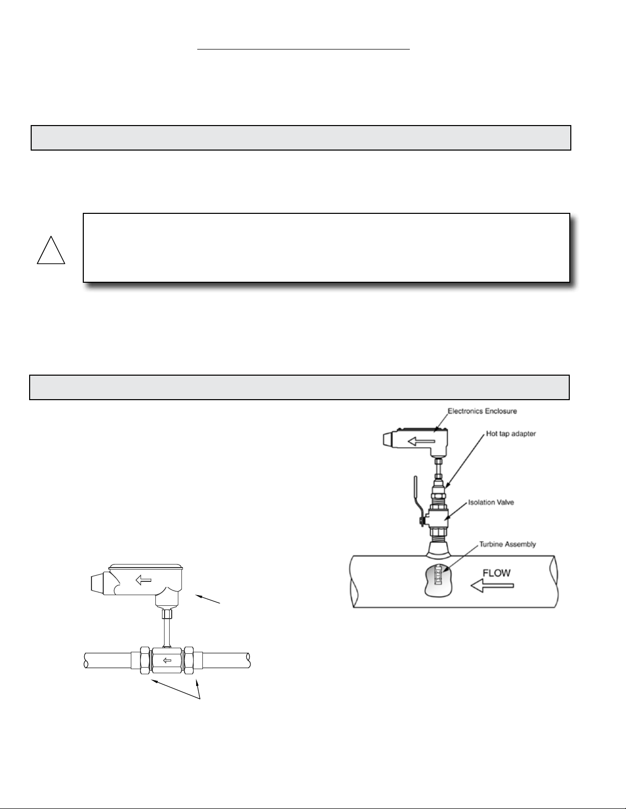
1.2 TYPICAL TURBINE FLOW METERS
ONICON’s Turbine Flow Meters measure the velocity
of owing liquids by counting the frequency at
which the blades of a rotating turbine pass a xed
electrode. Circuitry within the ow meter electronics
enclosure then converts the rotational rate to digital
and/or analog signals which are transmitted via
a connecting cable to any of ONICON’s display
devices, BTU meters and/or a data acquisition
system.
Electronics Enclosure
Insertion Meter
Sweat or NPT
Process Connections
Inline Meter
11451 Belcher Road South, Largo FL 33773 • USA • Tel +1 (727) 447-6140 • Fax (727) 442-5699 • sales@onicon.com
Turbine Flow Meter Manual 05/14 - 0721-3 / 13518 Page 4
Page 5

1.3 STANDARD FEATURES AND SPECIFICATIONS
(Refer to specication sheet for particular model
to obtain additional details)
ACCURACY
F-1100 / F-1200 / FB-1200 Series
± 0.5% OF READING at calibrated velocity
± 1% OF READING from 3 to 30 ft/s (10:1 range)
± 2% OF READING from 0.4 to 20 ft/s (50:1 range)
F-1300 Series
± 0.5% OF READING at calibrated velocity
± 2% of reading from 0.8 to 38 GPM (50:1 range)
Sensing Method
F-1100 / F-1300 Series
Single turbine electronic impedance sensing
(non-magnetic and non-photoelectric)
F-1200 / FB-1200 Series
Dual turbine electronic impedance sensing
(non-magnetic and non-photoelectric) and
frequency averaging circuitry.
Pipe Size Range
F-1100 Series
1¼” through 72” nominal
F-1200 / FB-1200 Series
2½” through 72” nominal
F-1300 Series
¾” or 1” NPT threaded or copper sweat process
connections
Supply Voltage
24±4 V AC/DC at 50 mA
Liquid Temperature Range
Standard: 140° F continuous, 150° F peak
High Temp: 280° F continuous, 300° F peak
Insertion meters operating above 250° F require
316 stainless steel construction option
Ambient Temperature Range
-5 to 160° F (-20 to 70° C)
Operating Pressure
400 PSI maximum
Pressure Drop
F-1100 / F-1200 / FB-1200 Series
Less than 1 PSI at 20 ft/s in 2½” pipe, decreasing
in larger pipes and lower velocities
F-1300 Series
3 PSI at maximum ow rate
Material
Wetted metal components
F-1100 / F-1200 / FB-1200 Series
Standard: Electroless nickel plated brass
Optional: 316 stainless steel
F-1300 Series
Brass sensor body
Electronics Enclosure
Standard: Weathertight aluminum enclosure
(NEMA4)
Optional: Submersible enclosure (NEMA6)
Electrical Connections
Standard: 10’ of PVC jacketed cable with ½”
NPT conduit connection
Optional: Indoor DIN connector with 10’ of
plenum rated cable
Output Signal(s)
F-1100 / F-1200 / F-1300 Series
Standard: Calibrated frequency output
(0-15 V pulse, 0-500 Hz)
Optional: Analog and digital outputs also
available, based on model
FB-1200 Series
Standard: Calibrated frequency output
(0-15 V pulse, 0-500 Hz), contact closure
output to report ow direction
Optional: Analog and digital outputs also
available, based on model
11451 Belcher Road South, Largo FL 33773 • USA • Tel +1 (727) 447-6140 • Fax (727) 442-5699 • sales@onicon.com
Turbine Flow Meter Manual 05/14 - 0721-3 / 13518 Page 5
Page 6
1.4 MODEL NUMBERING SYSTEM
F(B)-XX YY
SERIES OUTPUT SIGNAL
Frequency Output (15 V pulse)
F-11 Single Turbine, Insertion Type
F-12 Dual Turbine, Insertion Type
FB-12 Bi-Directional, Insertion Type
F-13 Inline Turbine Meter
Example: “F-1210” = Dual turbine, analog output
00
For connection to ONICON display or BTU meter
only. Signal is too fast for most building control
systems (0-500 Hz).
Analog Output (non-isolated) Provides both 4-20 mA
10
and 0-10 V outputs. Most commonly used output
type. (3-wire connection)
Isolated Analog Output
11
Provides both 4-20 mA and 0-10 V outputs. Signal
ground is isolated from power supply and pipe
ground. (4-wire connection)
Divided Output (Solid state dry contact) Provides an
20
isolated binary/digital output. Signal is divided to
limit the maximum frequency. For rate/totalization.
Scaled Output (Solid state dry contact)
30
Provides an isolated binary/digital output scaled to
provide one pulse per desired unit volume (e.g.: 1
pulse = 10 gal.).
Ideal for totalization applications.
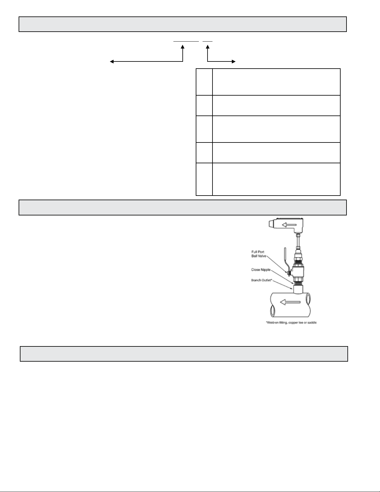
1.5 ADDITIONAL REQUIRED HARDWARE
All ONICON insertion type meters can be installed and removed
via a 1” or larger full port ball valve without stopping ow. The
terms “Standard” and “Hot Tap” refer to the installation method
of the isolation valve kit only.
Standard Installation Hardware: For new construction or
scheduled shutdown; once kit is installed, the ow meter can be
installed or removed without system shutdown.
Hot Tap Installation Hardware: For applications which require
the access hole in the pipe to be drilled through the valve
using a wet tap drilling machine, while the hydronic system is
pressurized and operating.
NOTE: Installation hardware materials vary greatly based on pipe
material, pipe size and standard vs. hot tap versions.
1.6 WARRANTY AND SERIAL NUMBER
Warranty
ONICON’s complete warranty is included in Appendix C of this manual as a part of the
“Conditions of Sale.” Meters purchased after November 1, 2000 include a two-year “No fault”
warranty which may cover accidental damage caused during installation or start up.
Serial Number
The serial number of your ow meter is located on a label on the side of the electronics enclosure.
The model number is also listed on this label. The serial number is a unique identier that you
should refer to, along with the model number, whenever you contact ONICON for assistance
regarding your meter.
11451 Belcher Road South, Largo FL 33773 • USA • Tel +1 (727) 447-6140 • Fax (727) 442-5699 • sales@onicon.com
Turbine Flow Meter Manual 05/14 - 0721-3 / 13518 Page 6
Page 7

SECTION 2.0: UNPACKING
Turbine ow meters are generally shipped in one package unless optional hardware or equipment is
ordered. This package may contain up to two complete meters along with the optional installation kits.
Any display equipment ordered with the meters, will be packed separately. Please open all packages
with caution to avoid damaging to their contents. In the event that anything is damaged when you
receive it, notify the shipping company immediately and the ONICON customer service department.
Most products are shipped insured unless the customer specically requests otherwise.
2.1 CHECKING THAT YOU HAVE RECEIVED EVERYTHING
The Documentation
Enclosed with each ow meter is a comprehensive documentation package which
includes the following items:
• Installation and Operation Guide
• Flow Meter Calibration Certicate
Please notify the ONICON customer service department if any documents are missing.
The Flow Meter
The ow meter was carefully packed prior to shipment and should arrive without any
damage. Prior to installation, inspect for physical damage such as broken turbine blades or
a damaged stem.
• Test the turbine(s) to see that they rotate freely when you gently blow on them
parallel to their shafts.
• Make sure that the threads on the insertion meter hot tap adapter have not been
damaged.
• Inspect the insertion meter stem for bends or other damage. The stem forms
the seal against liquid leakage as it slides through an ‘O’ ring inside the hot tap
adapter. Deep scratches may cause leakage.
• The serial and model numbers on the laminated wiring connection /calibration
data tag attached to the meter should match the numbers on the tag mounted
directly on the ow meter. Be sure that the unit was calibrated to the correct pipe
size and ow range.
11451 Belcher Road South, Largo FL 33773 • USA • Tel +1 (727) 447-6140 • Fax (727) 442-5699 • sales@onicon.com
Turbine Flow Meter Manual 05/14 - 0721-3 / 13518 Page 7
Page 8
SECTION 3.0: INSTALLATION, REMOVAL & ADJUSTMENT
!
! i !
WARNING
Insertion ow meters may often be installed in pipes which are under high pressure. Accidents
with these systems can cause serious injury or death. Only persons experienced with high pressure
systems and related knowledge in the heating, cooling and uid metering elds should attempt to
install adjust or remove the ow meter. Carefully read the installation and removal instructions in
this manual before performing any work on these meters.
ONICON will be happy to assist with technical recommendations and to provide guidance by
telephone or e-mail. On-site eld engineering, installation and service is also available at additional
cost.
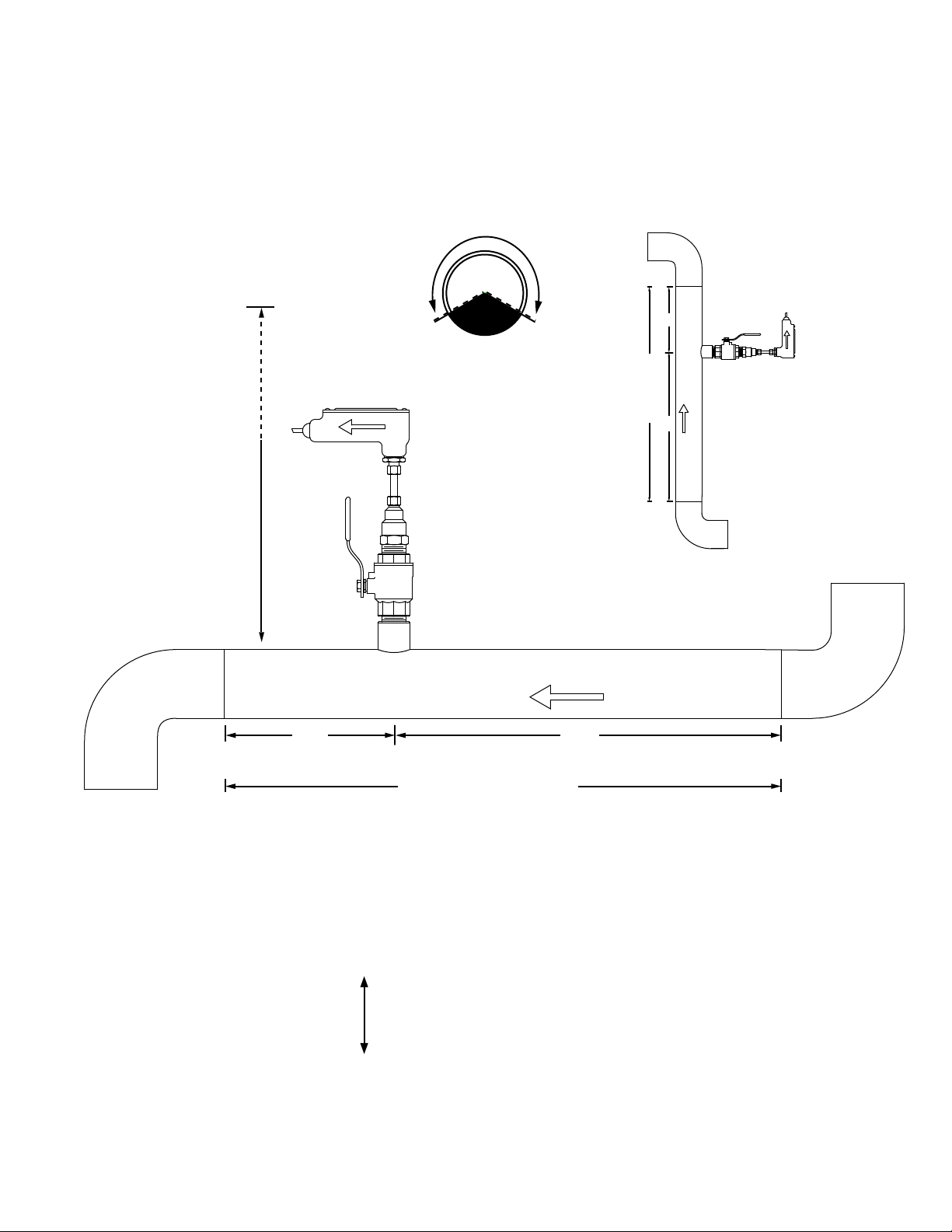
3.1 INSTALLATION SITE SELECTION
Install the ow meter where it will be accessible for personnel to perform necessary periodic
maintenance. The clearance required for insertion meter installations is typically 23”-36”
from the pipe wall to the nearest obstruction above the valve assembly. This clearance
dimension will increase with large diameter pipes. Allow at least 6” of clearance for inline
meter installations. The environment should be free of corrosive liquids/fumes, temperature
extremes and heavy vibration. The following information should be used as a guide to the
proper location for installing the meter.
GENERAL PRACTICES:
1. For best results, install the ow meter in a straight run of pipe, free of bends,
tees, valves, transitions, and obstructions.
2. Straight run requirements vary based on the nature of the upstream obstruction.
Review the following pages for guidelines in determining minimum
upstream straight run requirements based on the nature of the obstruction.
Note: Depending upon specic location details, more or less straight run may be
required to produce a satisfactory ow prole.
3. If there is insufcient straight run, allow 80% of the run upstream and 20% of the
run downstream. If the total length of straight run is less than 70% of the
recommended length, performance may seriously degrade, and consideration
should be given to changing to the series F-3000 In-line Electromagnetic Flow
Meter.
How To Determine The Available Straight Pipe Diameters:
For each application, locate the longest straight, unobstructed section of pipe (no bends, tees, valves,
other insertion probes, size transitions). The longest straight pipe run in inches divided by nominal
pipe size in inches equals “diameters of straight pipe.” For closed loop applications, consider both
the supply and return lines as possible locations.
IMPORTANT NOTE
Always use the maximum available straight run. When more than the minimum required
straight run is available, place the meter such that the excess straight run is upstream of the
meter location.
11451 Belcher Road South, Largo FL 33773 • USA • Tel +1 (727) 447-6140 • Fax (727) 442-5699 • sales@onicon.com
Turbine Flow Meter Manual 05/14 - 0721-3 / 13518 Page 8
Page 9
INSERTION AND INLINE FLOW METER SITE SELECTION
CLEARANCE
REQUIRED
CLEARANCE
FOR INSTALLATION
REQUIRED
FOR INSTALLATION
23” - 36”
Depending on
pipe size
23" - 36"
Allow at least
Depending on
6” for inline meters
pipe size
GENERAL GUIDELINES
(Shown with Insertion Meter)
• Install in vertical or horizontal pipe.
• For horizontal pipe position meter
anywhere in upper 240˚.
Downstream
Available Straight Run*
Upstream
20%
FLOW
80%
Vertical pipe position
(Downward ow is also allowed)
FLOW
20%
Downstream
80%
Upstream
Available Straight Run*
*See following pages for model specic straight run requirements.
EVALUATING UPSTREAM PIPING CONDITIONS
Straight Pipe
Single Bend
Pipe Reduction or Enlargement
Outowing Tees
Multiple Bends in Same Plane
Multiple Bends Out of Plane
Inowing Tees
Control Valves
Worse Better
11451 Belcher Road South, Largo FL 33773 • USA • Tel +1 (727) 447-6140 • Fax (727) 442-5699 • sales@onicon.com
Turbine Flow Meter Manual 05/14 - 0721-3 / 13518 Page 9
Page 10
FLOW DIRECTION
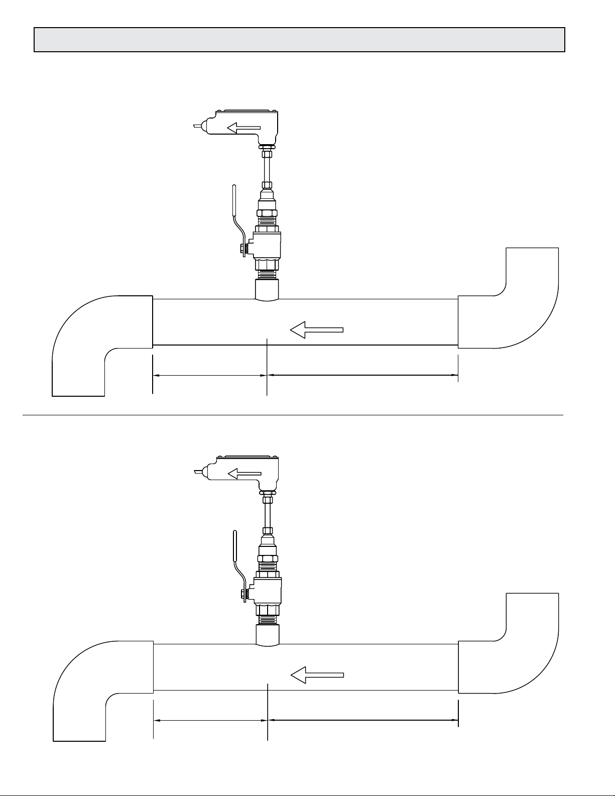
3.2 INSERTION METER STRAIGHT RUN REQUIREMENTS
STRAIGHT RUN REQUIREMENTS FOR INSERTION TURBINE FLOW METERS
Series F-1100 Single Turbine Flow Meters
FLOW DIRECTION
Minimum downstream
straight run distance
5 pipe diameters to any
valve, elbow, tting, etc.
GENERAL PRACTICES
1. For best results, install the ow meter in a straight run of pipe,
free of bends, tees, valves, transitions, and obstructions for a
distance of at least 20 pipe diameters upstream and 5 diameters
downstream.
2. Longer straight runs may be required in applications where the
meter is placed downstream from devices which cause unusual
ow prole disruption or swirl, for example, modulating valves or
two elbows in close proximity and out of plane, etc.
3. If there is not sufcient straight run, allow 80% of the run upstream and
20% of the run downstream. If the total length of straight run is less
than 20 diameters, performance may seriously
degrade, and consideration should be given to
changing to the series F-1200 Dual Turbine
Flow Meter.
FLOW DIRECTION
Minimum upstream
straight run distance
20 pipe diameters from any
valve, elbow, tting, etc.
Series F-1200 Dual Turbine Flow Meters
GENERAL PRACTICES
1. For best results, install the ow meter in a straight run of pipe,
free of bends, tees, valves, transitions, and obstructions for a
distance of 10 pipe diameters upstream and 5 diameters
Minimum downstream
straight run distance
5 pipe diameters to any
valve, elbow, tting, etc.
11451 Belcher Road South, Largo FL 33773 • USA • Tel +1 (727) 447-6140 • Fax (727) 442-5699 • sales@onicon.com
Turbine Flow Meter Manual 05/14 - 0721-3 / 13518 Page 10
downstream.
2. Longer straight runs may be required in applications where the
meter is placed downstream from devices which cause unusual
ow prole disruption or swirl, for example, modulating valves or
two elbows in close proximity and out of plane, etc.
3. If there is not sufcient straight run, allow 80% of the run upstream and
20% of the run downstream. If the total length of straight run is less
than 70% of recommended distance, performance
may degrade and consideration should be given to
changing to the F-3000 Series Inline
Electromagnetic ow meter.
FLOW DIRECTION
Minimum upstream
straight run distance
10 pipe diameters from any
valve, elbow, tting, etc.
Page 11

Series FB-1200 Dual Turbine Flow Meters
i
Bi-Directional Flow Applications
GENERAL PRACTICES
1. For best results, install the ow meter in a straight run of pipe,
free of bends, tees, valves, transitions, and obstructions for a
distance of at leas 10 pipe diameters on each side of the ow
meter.
2. Longer straight runs may be required in applications where
the meter is placed downstream from devices which cause
unusual ow prole disruption or swirl, for example,
modulating valves or two elbows in close proximity and out of
plane, etc.
3. If there is not sufcient straight run, allow 50% of the run up
stream and 50% of the run downstream. If the total length of
straight run is less than 70% of the recommended distance,
performance may degrade and
considerations should be given to
changing to the F-3000 Series Inline
Electromagnetic ow meter.
FLOW DIRECTION
SWITCH CLOSED
Minimum downstream
straight run distance
10 pipe diameters to any
valve, elbow, tting, etc.
FLOW DIRECTION
SWITCH OPEN
Minimum upstream
straight run distance
10 pipe diameters from any
valve, elbow, tting, etc.
Insufcient Straight Run Guidelines for Bi-directional Flow Applications
If there is insufcient available straight run, allow 50% of the run upstream and 50% of the run
downstream. If the total length of straight run is less than 20 diameters, performance may degrade
and consideration should be given to changing to the F-3100 or F-3200 In-line Electromagnetic
Flow Meters.
Some installations may work better with straight run optimized for ow in one direction. For
example, with ow meters installed in the bypass line between de-coupled constant volume
primary and variable secondary loops, it may be more important to accurately measure positive
ow (from supply to return.) Negative ow measurements (from return to supply) are generally
less critical, and it may be enough just to know that any negative ow is present. In this scenario,
maximizing straight run for positive ow might be a preferred strategy.
IMPORTANT NOTE
Always use the maximum available straight run. When more than the minimum required
straight run is available, place the meter such that the excess straight run is upstream of the
meter location.
11451 Belcher Road South, Largo FL 33773 • USA • Tel +1 (727) 447-6140 • Fax (727) 442-5699 • sales@onicon.com
Turbine Flow Meter Manual 05/14 - 0721-3 / 13518 Page 11
Page 12
3.3 INSERTION METER MECHANICAL INSTALLATION
!
! i !
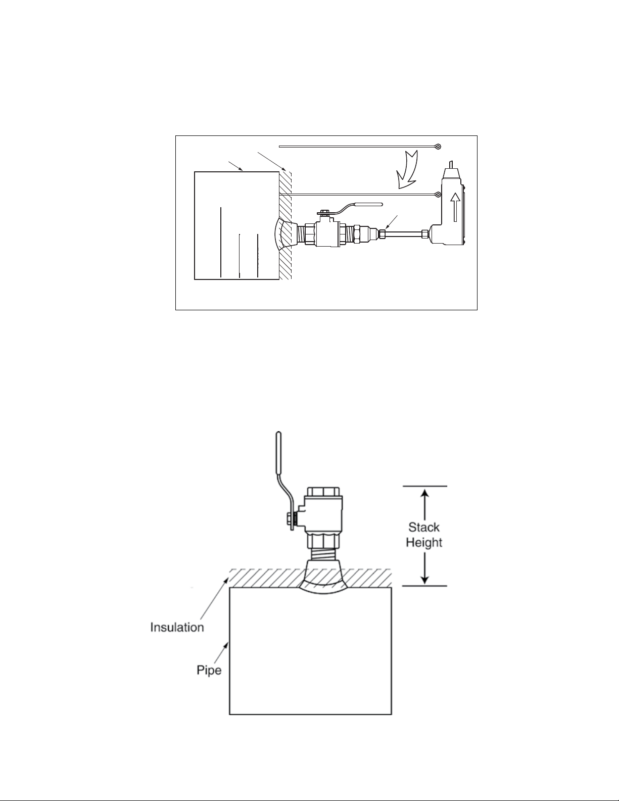
ONICON Insertion Turbine Flow Meters employ a hot tap adapter design that allows for
insertion and removal, when necessary, without interrupting ow and draining the pipe. To take
advantage of this feature, the ow meter must be installed through an isolation valve. The
installation must also allow for sufcient overhead clearance to fully extract the meter, and a full
1” opening in the pipe wall is required to clear the sensor head and allow for insertion. Make sure
that your valves and ttings are full port and at least 1” in actual internal diameter.
CLEARANCE
REQUIRED
FOR INSTALLATION
Typically
30" - 40"
23”- 36”
depending on
pipe size and
height of valve
assembly.
Standard Installation
Kit for Steel Pipe
Minimum Hole Size = 1"
Must be centered
1" Full port ball valve
1" Close nipple
1" Branch outlet
NOTE: Use stainless steel or brass
close nipple only.
1¼" for
hot tap
CAUTION
ONICON insertion style ow meters must be installed through a valve assembly. Failure to do so
negates the ability to remove the meter without shutting down ow and draining the system. It will
also result in an excessive amount of stem protruding from the pipe. Excessive stem lengths
unneccessarily expose the meter to incidental damage.
IMPORTANT NOTE
11451 Belcher Road South, Largo FL 33773 • USA • Tel +1 (727) 447-6140 • Fax (727) 442-5699 • sales@onicon.com
Turbine Flow Meter Manual 05/14 - 0721-3 / 13518 Page 12
Flow meters installed through oversized access holes will be subjected to undesirable turbulence
that may affect the accuracy of the meter.
Page 13

3.3.1 Insertion Meter Installation Kits
ONICON offers a wide range of installation hardware kits for commonly used pipe
materials. The kits are specically designed for ONICON insertion ow meters, and their
use is recommended. Refer to Appendix B of detailed infromation regarding ONICON
installation hardware kits.
The use of ONICON installation hardware kits accomplishes two important objectives.
First, it ensures that the proper hardware is used. Second, it simplies order processing
by standardizing the dimensions of the installation hardware. ONICON must have an
accurate measurement of the overall height of the installation hardware as measured from
the outside wall of the pipe to the top of the valve in order to determine the correct stem
length when assembling insertion meters in our factory. ONICON documents refer to this
dimension as the stack height.
ONICON installation hardware kits consist of three separate component parts:
Some type of
threaded branch
outlet,
interconnecting
An
close nipple,
And a full port
isolation valve.
Different pipe materials require different branch outlets and may include additional
bushings to properly size the opening.
3.3.2 ONICON Standard Installation Hardware Kits
Standard installation hardware kits are designed to be installed on piping systems that
are drained and at atmospheric pressure. The access hole is drilled (1” minimum) prior
to installation of the branch outlet with 1” NPT threads, the close nipple and full port ball
valve. Once the isolation valve is installed, the piping system can be ushed, lled and
pressurized. The ow meter may now be inserted or removed by hand without having to
stop ow or drain the system. Please read all instructions before proceeding with meter
insertion.
3.3.3 ONICON Hot Tap Installation Hardware Kits
ONICON offers an alternative installation hardware kit when it is not practical to relieve
pressure and drain the system. In this case, a 1¼” branch outlet, a close nipple and a 1¼”
full port ball valve are installed rst. Then, a hot tap drilling apparatus is used to drill a 1”
diameter hole through the valve. This eliminates the need to stop ow and drain the
pipe. Please read all instructions before proceeding with meter insertion.
11451 Belcher Road South, Largo FL 33773 • USA • Tel +1 (727) 447-6140 • Fax (727) 442-5699 • sales@onicon.com
Turbine Flow Meter Manual 05/14 - 0721-3 / 13518 Page 13
Page 14
!
3.3.4 Customer Supplied Installation Hardware
!
! i !
There are occasions where circumstances require that the customer provide the
installation hardware or that the ow meter be installed through existing hardware.
In these cases, it is important to conrm that the installation hardware is suitable for use
with the ow meter provided by ONICON before it is installed. The installation must
allow for sufcient overhead clearance to fully extract the meter and a full 1” opening in
the pipe wall is required to clear the sensor head and allow for insertion. Make sure that
your valves and ttings are full port and at least 1” in actual internal diameter.
Installation hardware generally consists of three separate component parts:
Some type of
threaded branch
outlet,
An
interconnecting
close nipple,
And a full port
isolation valve.
IMPORTANT NOTE
Do not use threaded steel or slip PVC tees to provide the 1” opening in the pipe. Tees of this
type will cause signicant errors in the ow measurement.
CAUTION
In order to provide the ow meter with the correct stem length, ONICON must know the
overall height of the installation hardware as measured from the outside wall of the pipe to
the top of the valve where the meter is installed.
CAUTION
Use stainless steel or brass nipple only.
11451 Belcher Road South, Largo FL 33773 • USA • Tel +1 (727) 447-6140 • Fax (727) 442-5699 • sales@onicon.com
Turbine Flow Meter Manual 05/14 - 0721-3 / 13518 Page 14
Page 15
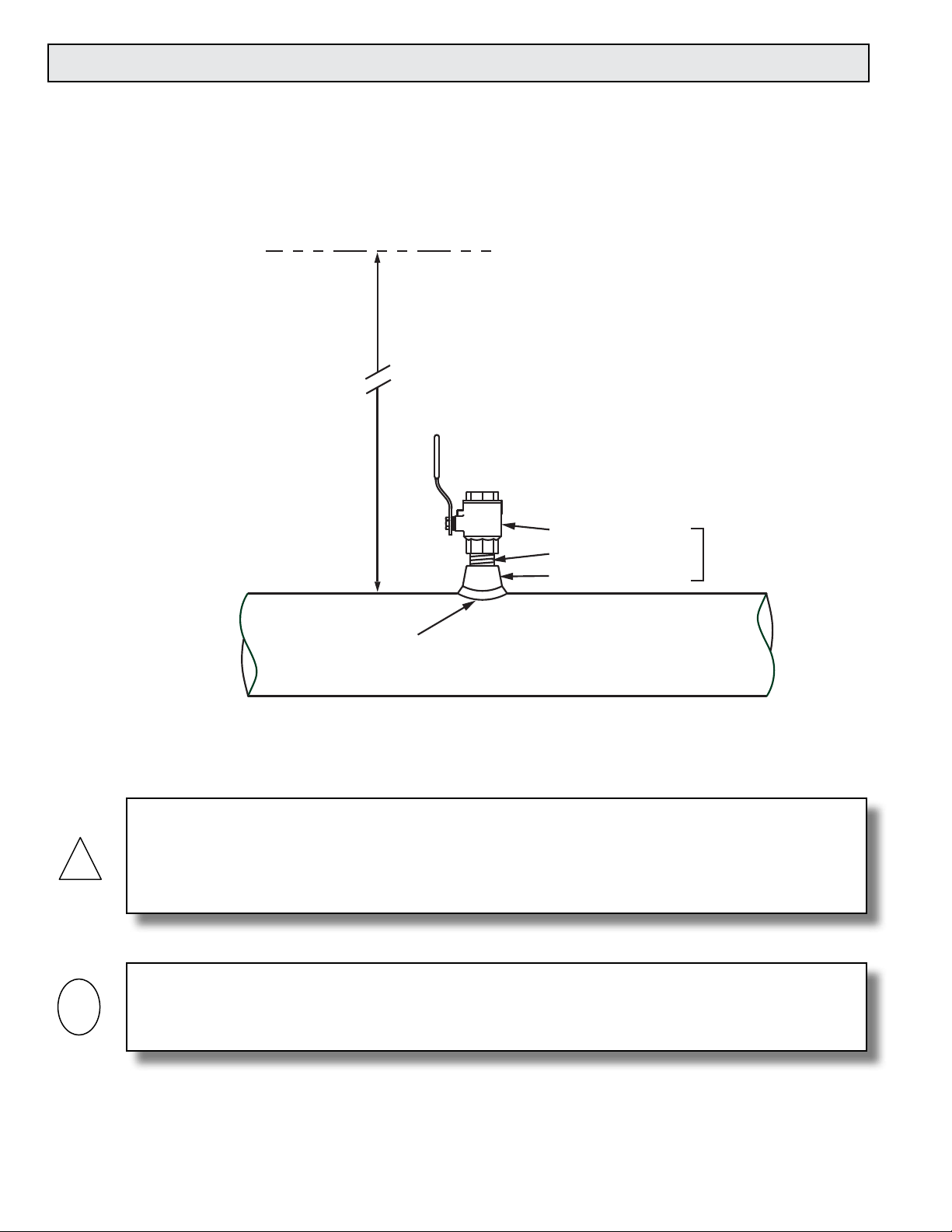
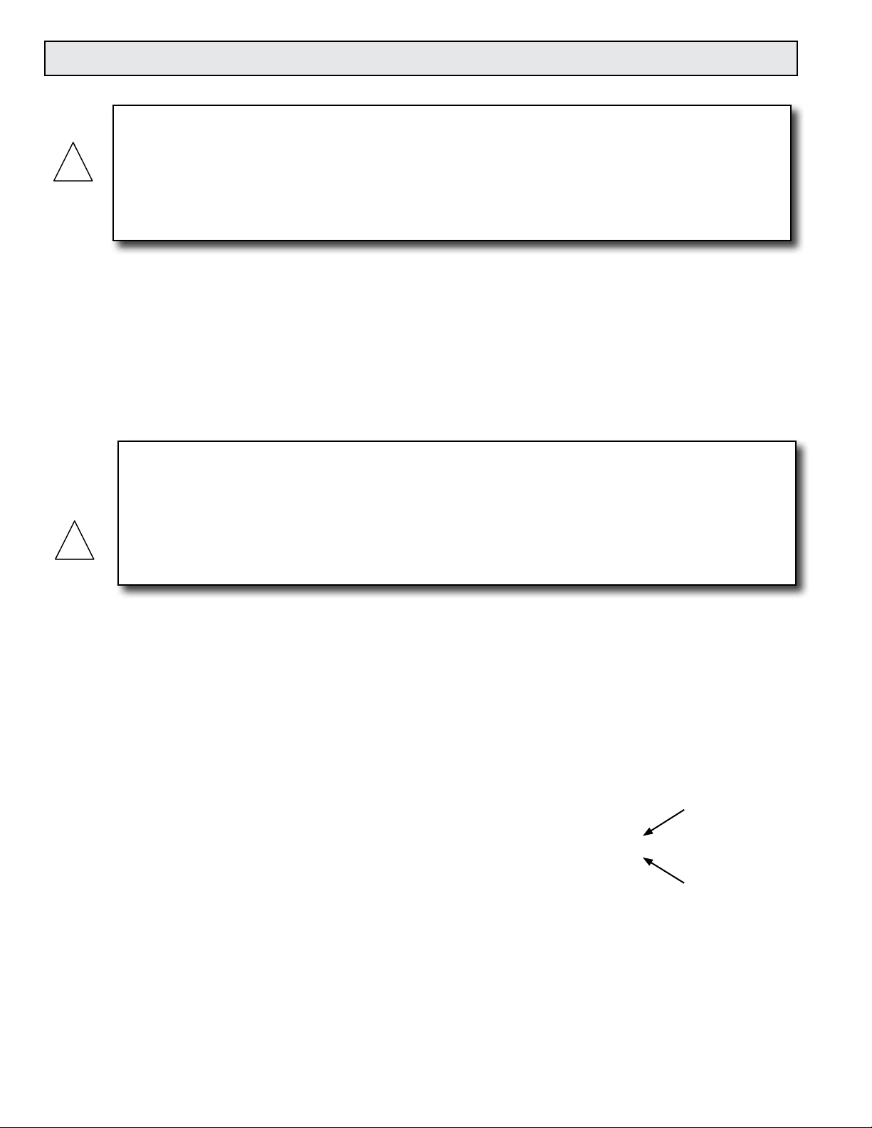
3.3.5 Conrming the Stack Height
ONICON insertion ow meter stem lengths vary according to the pipe diameter and the
height of the installation hardware stack. ONICON records the stack height dimension
provided by the customer at the time of order entry, and the information is used to size the
stem. This dimension is shown on the laminated insertion depth gage tag attached to the
meter.
Insulation
Pipe
GAGE LENGTH 10.937"
STACK HEIGHT 8.5”
FOR S/N #250791
ANY OTHER METER
DO NOT USE FOR
READ OTHER SIDE OF THIS TAG BEFORE INSTALLING METER
1) Pierce insulation until
gage tip touches pipe.
2) Insert flow meter until
bottom of electronics case
touches eye of depth gage.
Depth Gage
Flow Direction
Lock Nut
3) Confirm arrow is
aligned with flow
and tighten lock nut.
Prior to installing the meter, conrm that the stack height recorded on the tag is close to
the actual stack height. Flow meter stems are intentionally over sized to allow for
variations of at least 2” in the stack height. Contact ONICON prior to installation if there
is any question regarding stack height or stem length. This will allow ONICON to offer
you credit for your meter if you decide to exchange the meter for one with a different stem
length. Returns may be subject to a restocking fee.
11451 Belcher Road South, Largo FL 33773 • USA • Tel +1 (727) 447-6140 • Fax (727) 442-5699 • sales@onicon.com
Turbine Flow Meter Manual 05/14 - 0721-3 / 13518 Page 15
Page 16
3.4 INSTALLING THE INSERTION METER
!
!
WARNING
SYSTEM MAY BE UNDER HIGH PRESSURE. When installing the meter, adjusting its position
or removing the meter, be sure to hold the electronics enclosure rmly by hand before SLOWLY
loosening the positioning clamping nut. Failure to do this will allow the pressure to suddenly and
rapidly force the meter from the pipe causing serious injury. The meter could also be damaged or
break apart causing a break in the water seal with the resultant loss of large amounts of water. The
hand effort required to hold the meter will be 0.11 times the pipe pressure.
Begin by calculating the effort that will be required to hold the meter. Establish adequate footing for
this task, taking extra caution when working from a ladder or platform. Use the following formula:
E=0.11xP Where: E = effort in pounds
P = system pressure in pounds per square inch
Example: In a 300 PSI system, 33 pounds of effort is required to insert the meter into the pipe.
Installing the meter with a factory supplied depth gage:
WARNING
When you are ready to rell the system, make sure that all lines are lled with water before inserting
the turbine assembly into the stream. If the lines are not lled, air may interrupt the owing stream
and damage the turbine assembly. A greater danger is that if this is a hot water system, some water
may ash into steam and exceed the high temperature limit for the turbine and its mechanical
assembly. This ash over could exceed the pressure ratings of the meter and the assembly could fail
allowing steam and hot water to escape causing serious injury.
After tting the necessary plumbing hardware, ush the
entire system so that it is free of ux, solder and slag.
Prepare to install the ow meter by loosening the clamping
nut and withdrawing the turbine assembly fully into the
hot tap adapter. Next, thread the adapter on to the ball
valve using a paste type thread sealant. Do not use Teon
tape as torn strands of the tape may wind around the
turbine, slowing down or even stopping the turbine.
Check the installation for leaks by slightly opening the
ball valve. An ‘O’ ring in the adapter seals the meter
stem against leakage. If there are any leaks around the
clamping nut or stem, DO NOT ATTEMPT TO STOP THE
LEAKAGE BY OVERTIGHTENING THE CLAMPING
NUT. Damage to this nut or the clamping ring under the
nut may prevent the assembly from properly holding
the meter in the pipe. The clamping nut is not part of the
sealing mechanism. Any leaks in this area indicate that the
‘O’ ring is not sealing properly and you must contact the
factory for assistance.
Hot Tap
Adapter
Apply Paste
Type Sealant
to Threads
11451 Belcher Road South, Largo FL 33773 • USA • Tel +1 (727) 447-6140 • Fax (727) 442-5699 • sales@onicon.com
Turbine Flow Meter Manual 05/14 - 0721-3 / 13518 Page 16
Page 17

1. Open valve completely, loosen the position
!
!
!
!
clamping nut, and insert the meter until the
bottom of the electronics case touches the eye of
the depth gage. (Pierce insulation with gage until
the tip touches the pipe.)
2. Position the electronics enclosure parallel to
the pipe in the proper direction relative to the
ow. This will position the turbine with its axis
in line with the ow and in the correct direction.
Position
Clamping Nut
Insertion depth
gage provided
with each meter
3. Tighten the position clamping nut. Contact
ONICON for assitance when installing a meter
without a depth gage.
FLOW
CAUTION
Do not release the ow meter until you have tightened the position clamping nut enough to hold the
ow meter in the desired position. This will require less torque than you might think, so be careful
not to overtighten it and risk damaging the adapter, nut or stem.
NOTE: For installations with a limited straight run of pipe (less than the recommended distances
shown on pages 10 and 11), adjustments in insertion depth may be needed to compensate for
velocity ow prole variations. Please contact the factory for information on velocity ow
proling for determining the average velocity location in undeveloped ow locations.
3.4.1 Adjustment of the Meter Insertion Depth
WARNING
If adjustment of the meter depth is required, the same procedure must be followed as if the meter
were being removed. Please carefully read the section below on removal of the meter. Remember, the
meter may be under high pressure and failure to follow the procedure may result in serious injury.
3.5 REMOVAL OF THE INSERTION METER
WARNING
Remember, the meter may be under high pressure. And while removal of the meter is basically the
reverse of the insertion procedure detailed above, care must be taken to ensure that the meter is
supported against the pipe pressure before the position clamping nut is loosened. Failure to do this
will allow the pressure to suddenly and rapidly force the meter from the pipe causing serious injury.
WARNING
Prior to removal of the meter, make sure that you are standing on a secure platform and have both
hands available to manipulate the ow meter.
11451 Belcher Road South, Largo FL 33773 • USA • Tel +1 (727) 447-6140 • Fax (727) 442-5699 • sales@onicon.com
Turbine Flow Meter Manual 05/14 - 0721-3 / 13518 Page 17
Page 18

First support the ow meter against the pipe pressure
!
by holding the electronics enclosure rmly in hand
BEFORE loosening the position clamping nut. The
effort required is the same as that required for insertion
of the meter and should be calculated according to the
formula in section 3.4 covering insertion of the meter.
This effort will be 0.11 times the pipe pressure. If your
footing is not secure, or if your ability to hold the
meter is limited for any reason, DO NOT loosen the
clamping nut.
SLOWLY loosen the position clamping nut and
carefully and slowly allow the pressure to force the
meter out of the pipe. This is not at all difcult, but you
must not let go of the meter until it is fully withdrawn
into the hot tap adapter. Do not attempt to close the ball
valve until you are certain that the turbine assembly is
fully withdrawn into the hot tap adapter.
A common cause of damage to meters comes from
accidentally closing the valve and crushing the turbine
assembly. To avoid this, gently rotate the meter by
swinging the electronics enclosure back and forth
(twist the stem, do not bend it) while you slowly
close the valve. If the valve touches any part of the
meter, you will feel it as you are moving the meter. If
the valve touches anything, it means the meter is not
fully withdrawn. Usually a gentle twisting motion while withdrawing the meter will clear any
obstruction and permit the meter to withdraw completely. (Excessive build-up on the stem may
require the hot tap ‘O’ ring to be lubricated with silicone.)
Continue to hold the meter in place after the valve is completely closed to prevent the turbine
assembly from slipping back into the valve body. Slowly unscrew the hot tap adapter from the
valve. Once the adapter is loosened, allow pressure to vent from inside the hot tap adapter before
removing it from the valve. There will be a small amount of water inside the hot tap adapter. A
small container can be held under the valve to catch any spilled water. Once the meter has been
moved to its new depth, tighten the position clamping nut. Next, place several turns of electrical
tape around the stem just above the clamping nut so that at a later time, when the meter is
removed for service, it can be easily replaced at the same depth.
Position
Clamping Nut
WARNING
In hot water systems, even a small amount of water can cause serious personal injury. Use extra
caution when working with hot water meters.
11451 Belcher Road South, Largo FL 33773 • USA • Tel +1 (727) 447-6140 • Fax (727) 442-5699 • sales@onicon.com
Turbine Flow Meter Manual 05/14 - 0721-3 / 13518 Page 18
Page 19

3.6 INLINE METER STRAIGHT RUN REQUIREMENTS AND MECHANICAL INSTALLATION
Locating the meter
1. Install process connections (sweat or threaded end pieces) making certain to leave adequate
straight unobstructed pipe runs upstream and downstream of the meter location.
a. The minimum upstream straight run should be at least 20 diameters and the downstream
straight run should be at least 5 diameters in length.
b. If more than 25 diameters of straight run are available at the installation site the excess
straight run should be upstream of the meter location.
c. Please note that ONICON strongly recommends the use of strainers upstream of the meter
location.
d. ONICON also recommends the installation of isolation valves and a bypass loop to
accommodate servicing the meter.
TYPICAL INLINE METER INSTALLATION
Isolation Valve
Normally Open
5 Dia. Minimum
Straight Run
Downstream
20 Dia. Minimum
Straight Run
Upstream
Bypass Valve
Normally Closed
Isolation Valve
Normally Open
Installing the meter body
1. Make sure the unions are free of nicks or scratches on either end of the ow
meter body and on the process connections.
2. Spray the union faces with a silicone spray or apply a thin coat of beeswax to enhance
seating. Do not use paste thread sealant on union faces.
3. Recommended torques for union seal: 70 ft/lbs minimum
4. Make sure alignment of pipe does not put lateral stress on either joint.
y-Strainer
Upstream of
Flow Meter
Process
Connection
Process
Connection
Unions
11451 Belcher Road South, Largo FL 33773 • USA • Tel +1 (727) 447-6140 • Fax (727) 442-5699 • sales@onicon.com
Turbine Flow Meter Manual 05/14 - 0721-3 / 13518 Page 19
Page 20

!
3.7 WIRING CONNECTIONS
Make connections to the 10’ cable, which is supplied by ONICON and is pre-wired to the circuit
board.
CAUTION
Do not attempt to make any connections inside the electronics enclosure, or to remove factory
installed cable, strain relief or conduit tting. Damage resulting from these actions will not be
covered under warranty.
The most common cause of electronic failures are miswired connections. If you are adding
additional cable, please record any substitution of wire colors. If additional cable is purchased
from ONICON, the color code can be maintained. Cable from other sources will most likely have a
different set of colors. Please refer to Appendix A for wiring diagrams and factory color codes.
Only qualied service personnel should make connections between the ow meter and the user’s
external equipment. Any misapplication of power and/or ground can result in improper operation
or damage to the ow meter circuitry, and to any externally connected equipment.
Output signal(s)
to control
system
(if ordered)
Connect factory wires
to field wires in appropriate
ONICON
Display or
BTU Meter
(Optional)
junction box.
Leave sufficient slack in conduit
and cable to allow the meter to be
removed without disconnecting wires.
½” FNPT
conduit connection
FLOW
11451 Belcher Road South, Largo FL 33773 • USA • Tel +1 (727) 447-6140 • Fax (727) 442-5699 • sales@onicon.com
Turbine Flow Meter Manual 05/14 - 0721-3 / 13518 Page 20
Page 21

SECTION 4.0: STARTUP & COMMISSIONING FOR ONICON
TURBINE FLOW METERS
Leave sufficient slack in conduit
and cable to allow the meter to be
removed without disconnecting wires.
Position
Clamping Nut
4.1 HELPFUL HINTS FOR START-UP AND COMMISSIONING
Step-by-step procedures and companion worksheets are located on the next four pages. Please
read all installation instructions carefully before proceeding with start-up and commissioning.
Please read these helpful hints before proceeding with the start-up and commissioning procedure
on the next page.
1. ONICON ow meters are individually calibrated for a particular application. Be sure to
verify the pipe size and location.
2. The electronic sensing systems will not work in air. Blowing on the turbine(s) will
not produce a signal. You can test the meter by holding the turbines under a faucet or
carefully moving it back and forth in a bucket of water.
3. When measuring analog output signals, remember that current (mA) must be measured
in series, while voltage is measured in parallel. If the 4-20 mA signal is already
connected to a control system, you must break the connection and measure the signal
in series.
4. When measuring frequency outputs in Hertz, take your multimeter out of “autorange
mode” and manually set the range for a voltage level above 15 VDC. This will prevent
false readings when no turbine signal is present.
5. All wiring connections should be made at the end of the factory cable. Do not attempt
to remove the factory installed cable or change the orientation of the electronics
enclosure.
6. Never connect power to analog or frequency output signal wires. ONICON turbine ow
meters are not “loop-powered” devices.
7. Allow up to 45 seconds for signals to stabilize following power up.
11451 Belcher Road South, Largo FL 33773 • USA • Tel +1 (727) 447-6140 • Fax (727) 442-5699 • sales@onicon.com
Turbine Flow Meter Manual 05/14 - 0721-3 / 13518 Page 21
Page 22

4.2 INSERTION METER START-UP AND COMMISSIONING
Please read the entire procedure carefully before proceeding. Wiring diagrams are located in the
appendix A. A worksheet for checking off the following steps and recording measured values is
located on the following page.
Is the meter located in the correct location as required by the plans?
Conrm meter location
and adequate straight
1
pipe run to achieve
desired results.
2 Conrm pipe size.
Conrm insertion depth
3
and orientation.
Conrm control system
4
programming.
Conrm connection
to correct ONICON
5
display or BTU Meter
(if ordered).
Verify wiring before
6
connecting power.
Conrm correct supply
7
voltage.
8 Connect power. Wait approximately 45 seconds after power-on before proceeding further.
The following steps require ow in the pipe. Flow signal readings should be taken while holding the ow rate constant if possible;
otherwise, take the various output readings as quickly as possible.
Measure and
9
record frequency
output(s):
Compare actual straight pipe upstream and downstream of the meter location to recommended distances
identied in the installation manual. Note that the manual is very conservative, assuming worst-case pipe
obstructions. Contact ONICON to discuss specics of your application. If straight pipe run is very short,
consult factory PRIOR to installing a single turbine meter to discuss possibility of upgrade to a dual turbine
meter.
Conrm that the meter is tagged for the pipe size in which it is installed. When in doubt, measure the
circumference of the pipe. Pipe O.D. = (circumference / 3.14) – (insulation thickness x 2)
Each ow meter comes with an attached insertion gage and instruction tag. Ensure the meter is inserted to
the correct depth and that the electronics enclosure is parallel with the pipe, with the arrow in the direction
of ow.
Conrm that the control system input point is properly congured for the analog range (or digital pulse
factor) identied on the ow meter calibration tag & certicate
Conrm that the ow meter serial number matches the ONICON display or BTU meter serial number (when
ordered together).
Prior to connecting the power, verify that the wiring is correct as shown in this manual (and/or with the
additional wiring diagram provided with ONICON display or BTU meter.) If in doubt, call ONICON for
assistance before proceeding further.
Verify that 24 (+/- 4) V is available. Serial Numbers 115692 and later can accept 24 V DC or AC, but earlier
meters required 24 VDC. Note: ONICON display module or BTU meter provide 24 VDC to the ow meter.
ONICON display modules and BTU meters are typically powered by 120 VAC; however, low voltage versions
are also available.
The average frequency output signal is a 0-15 VDC pulsed output ranging up to 500 Hz and must be
measured with a frequency counter or oscilloscope. Measure DC frequency (Hz) from GREEN(+) to
BLACK(-). Also measure DC volts on same wires. Five to seven VDC is normal for a spinning turbine, 0 or
14+ VDC indicates a stopped turbine. (A reading of 1 to 4 VDC could indicate a problem)
GPM = Frequency in Hz X 60
Meter Factor in ppg (refer to calibration tag for meter factor)
For dual turbine models, also measure and record the top and bottom turbine signals.
TOP: WHITE(+) to BLACK(-) BOTTOM: ORANGE(+) to BLACK(-)
Measure and record
analog or digital
outputs.
Current Output:
10
Voltage (0-10V) Output:
Divided Output:
Scaled Output:
Compare various
output signals to each
11
other and to the ow
rate displayed by the
control system.
End of standard start-up and commissioning. Please contact ONICON at (727) 447-6140 with any questions.
Refer to ow meter wiring diagram for wire colors for the various outputs available based on your particular
ow meter model. Use the following formulas to calculate ow rate from measured analog signals:
GPM = (measured current in mA - 4) X Full Scale Analog Flow Rate
16
GPM = measured DC volts X Full Scale Analog Flow Rate
10
Same calculation as step 9, except use “divided meter factor” (measure and record frequency)
Each contact closure = unit volume identied as “Scale Factor” (measure and record time interval between
contact closures.)
The top and bottom turbine frequencies (dual) should ideally be within about 20% of each other and their
average should equal the average frequency output.
Compare the ow rates calculated in STEPS 9 and 10 to each other and to the ow rate indicated by the
control system. Refer to troubleshooting guide when readings are inconsistent.
11451 Belcher Road South, Largo FL 33773 • USA • Tel +1 (727) 447-6140 • Fax (727) 442-5699 • sales@onicon.com
Turbine Flow Meter Manual 05/14 - 0721-3 / 13518 Page 22
Page 23

4.3 INSERTION METER START-UP AND COMMISSIONING WORKSHEET
Please read all installation instructions carefully prior to proceeding with these steps. Wiring
diagrams are located in the appendix. Use the following worksheet for checking off the
commissioning steps and recording measured values:
STEP TEST / MEASUREMENT S/N: _______ S/N: _______ S/N: _______ S/N: ______
1 Meter location
2 Conrm pipe size
3 Insertion depth and orientation
4 Control system programming
5 Match display or BTU meter serial#
(if ordered)
6 Signal connections veried
7 Supply voltage veried
8 Connect power
The following steps require ow in the pipe. Flow signal readings should be taken while holding the ow rate constant if possible; otherwise, take the various output readings as quickly as possible.
9 Frequency output(s):
Avg = green, Top = white
Bottom = orange
Avg Freq. (HZ):
Hz
Hz
Hz
Hz
Avg Freq. (VDC):
Top Turbine (HZ):
Top Turbine (VDC):
Bottom Turbine (HZ):
Bottom Turbine (VDC):
Calculated Flow Rate:
10 Analog or digital outputs
4-20 mA signal:
0-10 V signal:
Scaled output time interval or
divided output frequency
Calculated Flow Rate:
11 Flow rate displayed by control
system
VDC
Hz
VDC
Hz
VDC
GPM GPM GPM GPM
MA
VDC
GPM GPM GPM GPM
GPM GPM GPM GPM
VDC
Hz
VDC
Hz
VDC
MA
VDC
VDC
Hz
VDC
Hz
VDC
MA
VDC
VDC
Hz
VDC
Hz
VDC
MA
VDC
11451 Belcher Road South, Largo FL 33773 • USA • Tel +1 (727) 447-6140 • Fax (727) 442-5699 • sales@onicon.com
Turbine Flow Meter Manual 05/14 - 0721-3 / 13518 Page 23
Page 24

4.4 INLINE METER START-UP AND COMMISSIONING
Please read the entire procedure carefully before proceeding. Wiring diagrams are located in the
appendix. A worksheet for checking off the following steps and recording measured values is
located on the following pages.
Conrm meter location
and adequate straight
1
pipe run to achieve
desired results.
Conrm control system
2
programming.
Conrm connection
to correct ONICON
3
display or BTU Meter
(if ordered).
Verify wiring before
4
connecting power.
Conrm correct supply
5
voltage.
6 Connect power. Wait approximately 45 seconds after power-on before proceeding further.
The following steps require ow in the pipe. Flow signal readings should be taken while holding the ow rate constant if possible;
otherwise, take the various output readings as quickly as possible.
Measure and
7
record frequency
output(s):
Measure and record
analog or digital
outputs.
Current Output:
8
Compare various
output signals to each
9
other and to the ow
rate displayed by the
control system.
End of standard start-up and commissioning. Please contact ONICON at (727) 447-6140 with any questions.
Voltage Output:
Divided Output:
Scaled Output:
Is the meter located in the correct location as required by the plans?
Compare actual straight pipe upstream and downstream of the meter location to recommended distances
identied in the installation manual. If straight pipe run is very short, consult ONICON PRIOR to installing
the meter.
Conrm that the control system input point is properly congured for the analog range (or digital pulse
factor) identied on the ow meter calibration tag & certicate
Conrm that the ow meter serial number matches the ONICON display or BTU meter serial number (when
ordered together).
Prior to connecting the power, verify that the wiring is correct as shown in this manual (and/or with the
additional wiring diagram provided with ONICON display or BTU meter.) If in doubt, call ONICON for
assistance before proceeding further.
Verify that 24 (+/- 4) V is available. Serial Numbers 115692 and later can accept 24 V DC or AC, but earlier
meters required 24 VDC. Note: ONICON display module or BTU meter provide 24 VDC to the ow meter.
ONICON display modules and BTU meters are typically powered by 120 VAC; however, low voltage versions
are also available.
The frequency output signal is a 0-15 VDC pulsed output ranging up to500 Hz and must be measured with a
frequency counter or oscilloscope. Measure DC frequency (Hz) from GREEN(+) to BLACK(-). Also measure
DC volts on same wires. Five to seven VDC is normal for a spinning turbine, 0 or 14+ VDC indicates a
stopped turbine. (1 to 4 VDC could indicate a problem)
GPM = Frequency in Hz X 60
Meter Factor in ppg (refer to calibration tag for meter factor)
Refer to ow meter wiring diagram for wire colors for the various outputs available based on your particular
ow meter model. Use the following formulas to calculate ow rate from measured analog signals:
GPM = (measured current in mA - 4) X Full Scale Analog Flow Rate
16
GPM = measured DC volts X Full Scale Analog Flow Rate
10
Same calculation as step 9, except use “divided meter factor” (measure and record frequency)
Each contact closure = unit volume identied as “Scale Factor” (measure and record time interval between
contact closures.)
Compare the ow rates calculated in STEPS 7 and 8 to each other and to the ow rate indicated by the
control system. Refer to troubleshooting guide when readings are inconsistent.
11451 Belcher Road South, Largo FL 33773 • USA • Tel +1 (727) 447-6140 • Fax (727) 442-5699 • sales@onicon.com
Turbine Flow Meter Manual 05/14 - 0721-3 / 13518 Page 24
Page 25

4.5 INLINE METER START-UP AND COMMISSIONING WORKSHEET
Please read all installation instructions carefully prior to proceeding with these steps. Wiring
diagrams are located in the appendix. Use the following worksheet for checking off the
commissioning steps and recording measured values:
STEP TEST / MEASUREMENT S/N: _______ S/N: _______ S/N: _______ S/N: ______
1 Meter location
2 Control system programming
3 Match display or BTU meter serial#
(if ordered)
4 Signal connections veried
5 Supply voltage veried
6 Connect power
The following steps require ow in the pipe. Flow signal readings should be taken while holding the ow rate
constant if possible; otherwise, take the various output readings as quickly as possible.
7 Frequency output(s):
Avg = green, Top = white
Bottom = orange
Avg Freq. (HZ):
Hz
Hz
Hz
Hz
Avg Freq. (VDC):
Calculated Flow Rate:
8 Analog or digital outputs
4-20 mA signal:
0-10 V signal:
Scaled output time interval or
divided output frequency
Calculated Flow Rate:
9 Flow rate displayed by control
system
VDC
GPM GPM GPM GPM
MA
VDC
GPM GPM GPM GPM
GPM GPM GPM GPM
VDC
MA
VDC
VDC
MA
VDC
VDC
MA
VDC
11451 Belcher Road South, Largo FL 33773 • USA • Tel +1 (727) 447-6140 • Fax (727) 442-5699 • sales@onicon.com
Turbine Flow Meter Manual 05/14 - 0721-3 / 13518 Page 25
Page 26

4.6 TROUBLESHOOTING GUIDE
NOTE: Also refer to the START-UP and COMMISSIONING GUIDE located on the preceding
pages.
REPORTED PROBLEM POSSIBLE SOLUTIONS
Verify that meter is inserted correctly into the pipe.
• Verify that the electronics enclosure is parallel with the pipe.
No signal
• Verify 24 V supply voltage.
• Verify correct wiring to control system (see wiring diagram).
• Check turbine(s) for debris.
• Conrm that there is adequate straight pipe run upstream of the
meter. Verify pipe size. Contact factory if pipe size is different
from calibration tag.
• Verify that meter is inserted correctly into the pipe.
• Verify that the electronics enclosure is parallel with the pipe.
Reading is too high or too low
• Verify correct wiring to control system (see wiring diagram).
• Conrm that output signals agree with each other (frequency vs.
analog, etc.)
• Conrm that control system is programmed for correct ow range
or scale factor.
• Check turbine(s) for debris.
Check for ground loop or offset voltage:
• Disconnect analog signal input to control system and measure
Analog signal seems high or
low and does not correspond
to frequency output
analog outputs directly from the ow meter.
• Re-connect signal input to control system and measure the analog
signals again.
• Any difference between these readings indicates a potential
ground loop or offset voltage.
• Please contact ONICON for further assistance.
Control system displays ow
rate, but no ow rate
indication on local display
module or BTU Meter
• Verify that all wires from ow meter were connected to the
display module or BTU meter.
• The frequency output wire (green) must be connected for any
ONICON display or BTU meter.
For technical assistance, contact ONICON at (727) 447-6140.
11451 Belcher Road South, Largo FL 33773 • USA • Tel +1 (727) 447-6140 • Fax (727) 442-5699 • sales@onicon.com
Turbine Flow Meter Manual 05/14 - 0721-3 / 13518 Page 26
Page 27

SECTION 5.0: ANALOG ADJUSTMENT PROCEDURE
ONICON electronic circuits are designed and tested to ensure long life with minimal drift. It
should not be necessary to make eld adjustments or calibrations. It may, however, be necessary
to rescale the analog output under the following conditions:
• The turbine was replaced with a new one that has a signicantly different meter factor.
• It is necessary change the full scale ow rate for the analog output.
• An analog output meter is being moved to a different size pipe.
ONICON will clean, test and recalibrate the meter for a small fee. One or two day turnaround
service is available when required. The information in this section is provided only for those
instances where you cannot return the meter service and factory calibration. ONICON will
provide assistance when performing this procedure via the telephone, if necessary.
While these adjustments are not complicated, they are crucial to the accuracy of the ow meter.
Adjustments should only be made by qualied personnel having an understanding of ow
equations and experience with control systems.
5.1 GENERAL DISCUSSION
ONICON insertion turbine ow meters measure the velocity of the uid owing in the pipe.
Proprietary electronic impedance sensing circuitry detects the rotation of a freely spinning axial
turbine, which is immersed in the ow stream. As each turbine blade passes a xed electrode,
an electronic pulse is produced by the circuitry. In the case of single turbine meters, the pulse
rate is then calibrated in terms of the number of pulses per gallon for whatever size pipe the user
has selected. This number is referred to as the METER FACTOR. For example an insertion ow
meter might have a meter factor of 31.3 PPG (Pulses per Gallon) in 3” pipe. The meter factor is the
calibration factor used to dene the calibrated frequency output signal provided by all ONICON
turbine meters. This frequency output signal can be used directly by some data acquisition
systems. Other systems will require additional signal conditioning. In those cases, ONICON uses
this signal to drive our analog and digital outputs.
Dual turbine meters provide the same calibrated frequency output except that the pulse rates from
the upper and lower turbines are electronically averaged and the calibration is done using this
average output signal.
5.2 ANALOG ADJUSTMENT PROCEDURE
This procedure adjusts both 4-20 mA & 0-10 V output signals. It is limited to meters with serial
numbers 115692 and higher. Contact ONICON for assistance if your meter’s serial number is
below 115692.
5.2.1 Equipment Required
• Multimeter: Capable of measuring voltage and current (mA)
(4½ digit true RMS meter recommended)
• Pulse Generator: 0-15 volt square pulse (0-10 volt minimum)
0-500Hz minimum operating range
Recommended resolution 0.01Hz (0.1 Hz minimum)
• Power Supply: 24 VAC or VDC ±4V
11451 Belcher Road South, Largo FL 33773 • USA • Tel +1 (727) 447-6140 • Fax (727) 442-5699 • sales@onicon.com
Turbine Flow Meter Manual 05/14 - 0721-3 / 13518 Page 27
Page 28

5.2.2 Procedure
1. Determine the input frequency required to simulate the desired maximum ow rate using the
equation below:
Where:
F = Input Frequency (Hz)
R = Maximum Flow Rate
MF = Meter Factor*
*The meter factor is written on a calibration tag attached to each meter and is also
recorded on the calibration data sheet. Use one of the three formulas provided based
on the engineering units for the meter factor. Please contact ONICON if you cannot
locate the meter factor, or if you wish to use the meter in a different pipe size.
For GPM For l/s For M3/hr
MF in pulses per gallon (ppg) MF in pulses per liter (ppl) MF in pulses per meter3 (ppm3)
F = R x MF
60
F = R x MF F = R x MF
3600
2. Remove the ow meter from the pipe and make sure the electrode and the surrounding area
are dry.
3. Choose the input frequency range (Hz) from the table on the next page and set the appropriate
range selection jumper. Refer to Appendix A for the internal wiring diagram of your model.
4. Connect the pulse generator output lead to the test signal input lead on the analog card, and
connect the pulse generator ground lead to the black ground wire in the ow meter cable. Set
the output to a 15 V P-P square wave at the frequency determined in step #1.
5. Set the DC voltmeter to the 0-10 V scale and connect the (+) lead to the brown wire in the ow
meter cable. Connect the (-) lead from the voltmeter to the black ground wire in the ow meter
cable.
6. Connect the red and black wires in the ow meter cable to the (+) and (-) terminals of the 24 V
power supply respectively. Apply power.
7. Adjust the span potentiometer on the analog card to produce a 10 V reading on the voltmeter.
NOTE: The frequency ranges in the table below are a starting point, and since they vary with
electronic component tolerance, it may be necessary to change the jumper position once rescaling
is started. If the range of adjustment of the span potentiometer is not sufcient to produce the
desired 10 VDC, change the jumper position as follows:
VOLTAGE READING TOO HIGH: Choose the next lower jumper position.
VOLTAGE READING TOO LOW: Choose the next higher jumper position.
8. The ow meter is now rescaled. Disconnect all equipment, replace the cover and reinstall the
ow meter.
Analog Range Jumper Settings
INPUT FREQUENCY (Hz) SWITCH POSITION
AT MAXIMUM FLOW RATE SINGLE/DUAL TURBINE
Over 248 Hz 1
124 – 248 Hz 2
62 – 123 Hz 3
31 – 61 Hz 4
15 – 30 Hz 5
Under 15 Hz 6
11451 Belcher Road South, Largo FL 33773 • USA • Tel +1 (727) 447-6140 • Fax (727) 442-5699 • sales@onicon.com
Turbine Flow Meter Manual 05/14 - 0721-3 / 13518 Page 28
Page 29

APPENDIX A
User Connections and Internal Wiring Diagrams
11451 Belcher Road South, Largo FL 33773 • USA • Tel +1 (727) 447-6140 • Fax (727) 442-5699 • sales@onicon.com
Turbine Flow Meter Manual 05/14 - 0721-3 / 13518 Page A-1
Page 30

FLOW METER WIRING INFORMATION
FLOW METER WIRING INFORMATION
User Connections for Models with Frequency Output
Models: F-1100, F-1200, FB-1200 & F-1300
User Connections for Models with Frequency Output
Models: F-1100, F-1200, FB-1200 & F-1300
Wiring Information
F-1300
√
Inline
F-1200
√ √
√ √
FB-1200
Dual Turbine
Bi-Directional
RED
*
BLACK
WIRE COLOR CODE NOTES
(+) 24 ± 4 V AC/DC
supply voltage
(–) Common ground
(Common with pipe ground)
F-1100
Single Turbine
√
√ √
Connect to power supply
positive
Connect to power supply
negative
√ √
√ √
√
GREEN
GRAY
(+) Frequency output signal:
0-15 V peak pulse
Dry contact directional
output - indicates
√
VIOLET
flow direction
DIAGNOSTIC SIGNALS
ORANGE
√
√
WHITE
√
√
Bottom turbine frequency
Top turbine frequency
F-1100 / F-1200 / F-1300 Wiring Diagram
Flow Meter Connections to ONICON Display or BTU Meter
ONICON Display
RED
GREEN
BLACK
WHITE
ORANGE
FLOW METER
F-1200 only
or BTU Meter
+ 24 V
FREQUENCY INPUT
GROUND
TOP TURBINE
BOTTOM TURBINE
SHIELD
Output frequency is typically
below 200 Hz, but can be
up to 300 Hz
Contact closed when flow
is in direction of arrow
on meter
These signals are for
diagnostic purposes connect to local display
or BTU meter
FB-1200 Wiring Diagram
Connections to ONICON Display or BTU Meter
ONICON Display
RED
GREEN
BLACK
WHITE
ORANGE
FLOW METER
GRAY
VIOLET
or BTU Meter
+ 24 V
FREQUENCY INPUT
GROUND
TOP TURBINE
BOTTOM TURBINE
DIRECTIONAL
CONTACTS
SHIELD
NOTES: * 1. Serial Numbers 115691 and earlier require 24 VDC. Serial Numbers 115692 and higher
can accept 24 V AC/DC.
2. Black wire is common with the pipe (typically earth ground).
3. For ONICON display module or BTU meter, connect all wires provided. Refer to wiring diagram
provided with display or BTU meter.
0271
11451 Belcher Road South, Largo FL 33773 • USA • Tel +1 (727) 447-6140 • Fax (727) 442-5699 • sales@onicon.com
Turbine Flow Meter Manual 05/14 - 0721-3 / 13518 Page A-2
Page 31

WIRING DIAGRAM
INTERNAL CONNECTIONS FOR FREQUENCY
OUTPUT FLOW METERS
MODELS F-1100 / F-1200 / F-1300
For use with serial numbers 115692 and later
FREQUENCY BOARD
TEST SIGNAL INPUT
BLACK WIRE (BOARD TO BOARD)
GREEN WIRE (BOARD TO BOARD)
RED WIRE (BOARD TO BOARD)
SENSING BOARD
TOP TURBINE:
F-1200 ONL Y
(WHITE WIRE)
BOTTOM TURBINE:
F-1200 ONL Y
(ORANGE WIRE)
FREQUENCY OUTPUT
(GREEN WIRE)
COMMON GROUND
(BLACK WIRE)
+24V AC/DC SUPPLY
(RED WIRE)
EXTERNAL CABLE CONNECTIONS
0066-1
EXTERNAL CABLE
NOTE: INTERNAL CONNECTIONS
OMITTED FOR CLARITY
NOTES:
11451 Belcher Road South, Largo FL 33773 • USA • Tel +1 (727) 447-6140 • Fax (727) 442-5699 • sales@onicon.com
Turbine Flow Meter Manual 05/14 - 0721-3 / 13518 Page A-3
Page 32

FLOW METER WIRING INFORMATION
!
User Connections for Models with Non-Isolated Analog Outputs
Models: F-1110, F-1210, FB-1210 & F-1310
Wiring Information
F-1110
Single Turbine
√
√
√
√
√
F-1310
√
√
√
√
√
Inline
√
√
√
√
√
F-1210
Dual Turbine
√
√
√
√
√
√
√
FB-1210
Bi-Directional
RED
*
BLACK
GREEN
BLUE
BROWN
GRAY
VIOLET
WIRE COLOR CODE NOTES
(+) 24 ± 4 V AC/DC
supply voltage
(–) Common ground
(Common with pipe ground)
(+) Frequency output signal:
0-15 V peak pulse
(+) Analog signal:
4-20 mA (non-isolated)
(+) Analog signal:
0-10 V (non-isolated)
(Can also be ordered
as 0-5 V)
Dry contact directional
output - indicates
flow direction
Connect to power supply
positive
Connect to power supply
negative & analog input
ground
Required when meter
is connected to local
display or BTU meter
Both signals may be
used independently
(unless 0-5 V output
is ordered)
Contact closed when flow
is in direction of arrow
on meter
DIAGNOSTIC SIGNALS
ORANGE
√
√
WHITE
√
√
Bottom turbine frequency
Top turbine frequency
F-1110 / F-1210 / F-1310 Wiring Diagram
Connections to a Control System (No Display or BTU Meter)
Power
RED
BLACK
BLUE
BROWN
FLOW METER
NOTES: * 1. Serial Numbers 115691 and earlier require 24 VDC. Serial Numbers 115692 and higher
can accept 24 V AC/DC.
2. Black wire is common with the pipe (typically earth ground).
3. For ONICON display module or BTU meter, connect all wires provided. Refer to wiring diagram
provided with display or BTU meter.
4. This is NOT a "loop-powered" instrument. DO NOT connect power to any of the signal
output wires (blue, brown, green, orange or white)
OR
Source
+ 24 V
COM
Control System
SIGNAL GROUND
ANALOG SIGNAL INPUT
CAUTION
These signals are for
diagnostic purposes connect to local display
or BTU meter
FB-1210 Wiring Diagram
Connections to a Control System (No Display or BTU Meter)
Power
RED
BLACK
BLUE
BROWN
FLOW METER
GRAY
VIOLET
OR
Source
+ 24 V
COM
Control System
SIGNAL GROUND
ANALOG INPUT
BINARY (DIGITAL) INPUT
(Direction)
This is NOT a “loop-powered” instrument. DO NOT connect power to any of the signal output
wires (blue, brown, green, orange or white)
0272
11451 Belcher Road South, Largo FL 33773 • USA • Tel +1 (727) 447-6140 • Fax (727) 442-5699 • sales@onicon.com
Turbine Flow Meter Manual 05/14 - 0721-3 / 13518 Page A-4
Page 33

WIRING DIAGRAM
INTERNAL CONNECTIONS FOR
NON-ISOLATED ANALOG OUTPUT
FLOW METERS
MODELS F-1110 / F-1210 / F-1310
For use with serial numbers
115692 and later
ANALOG BO
TEST SIGNAL INPUT
RANGE JUMPER
(FACTORY SELECTED)
4 mA ZERO ADJUST
BLACK WIRE (BOARD TO BOARD)
GREEN WIRE (BOARD TO BOARD)
RED WIRE (BOARD TO BOARD)
10 V & 20 mA SPAN ADJUST
ARD
SENSING BOARD
TOP TURBINE:
F-1210 ONLY
(WHITE WIRE)
BOTTOM TURBINE:
F-1210 ONLY
(ORANGE WIRE)
4-20 mA OUTPUT
(BLUE WIRE)
0-10 V OUTPUT
(BROWN WIRE)
FREQUENCY OUTPUT
(GREEN WIRE)
COMMON GROUND
(BLACK WIRE)
EXTERNAL CABLE CONNECTIONS
24V AC/DC SUPPLY
(RED WIRE)
0016-2
EXTERNAL CABLE
NOTE: CONNECTIONS
OMITTED FOR CLARITY
NOTES:
11451 Belcher Road South, Largo FL 33773 • USA • Tel +1 (727) 447-6140 • Fax (727) 442-5699 • sales@onicon.com
Turbine Flow Meter Manual 05/14 - 0721-3 / 13518 Page A-5
Page 34

FLOW METER WIRING INFORMATION
!
User Connections for Models with Isolated Analog Outputs
Models: F-1111, F-1211, FB-1211 & F-1311
Wiring Information
F-1111
Single Turbine
√
F-1311
√
Inline
√
F-1211
Dual Turbine
√
FB-1211
Bi-Directional
RED
*
WIRE COLOR CODE NOTES
(+) 24 ± 4 V AC/DC
supply voltage
Connect to power supply
positive
BLACK
√
√
√
√
√
√
√
√
√
√
√
√
√
√
√
√
√
√
√
√
GREEN
BLUE
BROWN
YELLOW
GRAY
VIOLET
ORANGE
WHITE
√
√
√
√
√
√
(–) Common ground
(Common with pipe ground)
(+) Frequency output signal:
0-15 V peak pulse
(+) Analog signal:
4-20 mA (isolated)
(+) Analog signal:
0-10 V (isolated)
(Can also be ordered
as 0-5 V)
(–) Isolated ground
Dry contact directional
output - indicates
flow direction
Bottom turbine frequency
Top turbine frequency
F-1111 / F-1211 / F-1311 Wiring Diagram
Connections to a Control System (No Display or BTU Meter)
Power
RED
BLACK
BLUE
BROWN
YELLOW
FLOW METER
OR
Source
+ 24 V
COM
Control System
ANALOG SIGNAL INPUT
SIGNAL GROUND
Connect to power supply
negative
Required when meter
is connected to local
display or BTU meter
Both signals may be
used independently
(unless 0-5 V output
is ordered)
Use for analog signals only
Contact closed when flow
is in direction of arrow
on meter
DIAGNOSTIC SIGNALS
These signals are for
diagnostic purposes connect to local display
or BTU meter
FB-1211 Wiring Diagram
Connections to a Control System (No Display or BTU Meter)
FLOW METER
RED
BLACK
BLUE
BROWN
YELLOW
GRAY
VIOLET
OR
Power
Source
+ 24 V
COM
Control System
ANALOG INPUT
SIGNAL GROUND
BINARY (DIGITAL) INPUT
(Direction)
NOTES: * 1. Serial Numbers 115691 and earlier require 24 VDC. Serial Numbers 115692 and higher
can accept 24 V AC/DC.
2. Black wire is common with the pipe (typically earth ground).
3. For ONICON display module or BTU meter, connect all wires provided. Refer to wiring diagram
provided with display or BTU meter.
4. This is NOT a "loop-powered" instrument. DO NOT connect power to any of the signal
output wires (blue, brown, green, orange or white)
CAUTION
This is NOT a “loop-powered” instrument. DO NOT connect power to any of the signal output
wires (blue, brown, green, orange or white)
0273
11451 Belcher Road South, Largo FL 33773 • USA • Tel +1 (727) 447-6140 • Fax (727) 442-5699 • sales@onicon.com
Turbine Flow Meter Manual 05/14 - 0721-3 / 13518 Page A-6
Page 35

WIRING DIAGRAM
INTERNAL CONNECTIONS FOR
ISOLATED ANALOG OUTPUT
FLOW METERS
MODELS F-1111 / F-1211 / F-1311
For use with serial numbers
115692 and later
ISOLATED ANALOG BOARD
TEST SIGNAL INPUT
RANGE JUMPER
(FACTORY SELECTED)
4 mA ZERO ADJUST
BLACK WIRE (BOARD TO BOARD)
GREEN WIRE (BOARD TO BOARD)
RED WIRE (BOARD TO BOARD)
10 V & 20 mA SPAN ADJUST
SENSING BOARD
TOP TURBINE:
F-1211 ONLY
(WHITE WIRE)
BOTTOM TURBINE:
F-1211 ONLY
(ORANGE WIRE)
ISOLATED GROUND
(YELLOW WIRE)
4-20 mA OUTPUT
(BLUE WIRE)
0-10 V OUTPUT
(BROWN WIRE)
FREQUENCY OUTPUT
(GREEN WIRE)
COMMON GROUND
(BLACK WIRE)
+24V AC/DC SUPPLY
(RED WIRE)
EXTERNAL CABLE CONNECTIONS
EXTERNAL CABLE
NOTE: INTERNAL CONNECTIONS
OMITTED FOR CLARITY
NOTES:
0068-2
11451 Belcher Road South, Largo FL 33773 • USA • Tel +1 (727) 447-6140 • Fax (727) 442-5699 • sales@onicon.com
Turbine Flow Meter Manual 05/14 - 0721-3 / 13518 Page A-7
Page 36

FLOW METER WIRING INFORMATION
User Connections for Models with Divided Output
Models: F-1120, F-1220, FB-1220 & F-1320
Wiring Information
F-1120
Single Turbine
√
F-1320
√
Inline
√
F-1220
Dual Turbine
√
FB-1220
Bi-Directional
RED
*
WIRE COLOR CODE NOTES
(+) 24 ± 4 V AC/DC
supply voltage
Connect to power supply
positive
BLACK
√
√
√
√
√
√
√
√
√
√
√
√
√
√
√
√
√
GREEN
BLUE
BROWN
GRAY
VIOLET
ORANGE
WHITE
√
√
√
√
√
(–) Common ground
(Common with pipe ground)
(+) Frequency output signal:
0-15 V peak pulse
Dry contact divided
output - indicates
flow rate
Dry contact directional
output - indicates
flow direction
Bottom turbine frequency
Top turbine frequency
F-1120 / F-1220 / F-1320 Wiring Diagram
Connections to a Control System (No Display or BTU Meter)
Power
RED
BLACK
BLUE
BROWN
FLOW METER
Source
+ 24 V
COM
Control System
BINARY (DIGITAL) INPUT
Connect to power supply
negative
Required when meter
is connected to local
display or BTU meter
Output can be divided by
any binary number up to
4096 to meet frequency
limitations of control system
Contact closed when flow
is in direction of arrow
on meter
DIAGNOSTIC SIGNALS
These signals are for
diagnostic purposes connect to local display
or BTU meter
FB-1220 Wiring Diagram
Connections to a Control System (No Display or BTU Meter)
FLOW METER
RED
BLACK
BLUE
BROWN
GRAY
VIOLET
Power
Source
24 V
COM
Control System
BINARY (DIGITAL) INPUT
(Rate)
BINARY (DIGITAL) INPUT
(Direction)
NOTES: * 1. Serial Numbers 115691 and earlier require 24 VDC. Serial Numbers 115692 and higher
can accept 24 V AC/DC.
2. Black wire is common with the pipe (typically earth ground).
3. For ONICON display module or BTU meter, connect all wires provided. Refer to wiring diagram
provided with display or BTU meter.
0274
11451 Belcher Road South, Largo FL 33773 • USA • Tel +1 (727) 447-6140 • Fax (727) 442-5699 • sales@onicon.com
Turbine Flow Meter Manual 05/14 - 0721-3 / 13518 Page A-8
Page 37

WIRING DIAGRAM
INTERNAL CONNECTIONS FOR
DIVIDED OUTPUT FLOW METERS
MODELS F-1120 / F-1220 / F-1320
For use with serial numbers
115692 and later
DIVIDER BOARD
1:1 JUMPER AT
THIS END
TEST SIGNAL INPUT
1:1 JUMPER AT THIS END
DIVIDER JUMPER BLOCK
BLACK WIRE (BOARD TO BOARD)
GREEN WIRE (BOARD TO BOARD)
RED WIRE (BOARD TO BOARD)
AVAILABLE BINARY DIVIDER
SELECTIONS
SELECT ONLY ONE VALUE
OR THE DIVISION WILL
NOT BE CORRECT
1:1
1:2
1:4
1:8
1:16
NOTES:
SENSING BOARD
TOP TURBINE:
F-1220 ONLY
(WHITE WIRE)
BOTTOM TURBINE:
F-1220 ONLY
(ORANGE WIRE)
(BROWN WIRE)
DIVIDED OUTPUT SWITCH
(BLUE WIRE)
FREQUENCY OUTPUT
(GREEN WIRE)
COMMON GROUND
(BLACK WIRE)
24V AC/DC SUPPLY
(RED WIRE)
EXTERNAL CABLE
NOTE: INTERNAL CONNECTIONS
OMITTED FOR CLARITY
EXTERNAL CABLE CONNECTIONS
1:32
1:64
1:128
1:256
1:512
1:1024
1:2048
1:4096
0069-1
11451 Belcher Road South, Largo FL 33773 • USA • Tel +1 (727) 447-6140 • Fax (727) 442-5699 • sales@onicon.com
Turbine Flow Meter Manual 05/14 - 0721-3 / 13518 Page A-9
Page 38

FLOW METER WIRING INFORMATION
User Connections for Models with Scaled Output
Models: F-1130, F-1230, FB-1230 & F-1330
Wiring Information
F-1130
Single Turbine
√
F-1330
√
Inline
√
F-1230
Dual Turbine
√
FB-1230
Bi-Directional
RED
*
WIRE COLOR CODE NOTES
(+) 24 ± 4 V AC/DC
supply voltage
Connect to power supply
positive
BLACK
√
√
√
√
√
√
√
√
√
√
√
√
√
√
√
√
√
GREEN
BLUE
BROWN
GRAY
VIOLET
ORANGE
WHITE
√
√
√
√
√
(–) Common ground
(Common with pipe ground)
(+) Frequency output signal:
0-15 V peak pulse
Dry contact scaled
output
Dry contact directional
output - indicates
flow direction
Bottom turbine frequency
Top turbine frequency
F-1130 / F-1230 / F-1330 Wiring Diagram
Connections to a Control System (No Display or BTU Meter)
Connect to power supply
negative
Required when meter
is connected to local
display or BTU meter
Scaled to provide one
pulse per volumetric unit
Examples:
1 pulse per 10 gal.
1 pulse per 100 gal.
Contact closed when flow
is in direction of arrow
on meter
DIAGNOSTIC SIGNALS
These signals are for
diagnostic purposes connect to local display
or BTU meter
FB-1230 Wiring Diagram
Connections to a Control System (No Display or BTU Meter)
Power
Source
+ 24 V
COM
Control System
BINARY (DIGITAL) INPUT
(Rate)
BINARY (DIGITAL) INPUT
(Direction)
RED
BLACK
BLUE
BROWN
FLOW METER
Power
Source
+ 24 V
COM
Control System
BINARY (DIGITAL) INPUT
RED
BLACK
BLUE
BROWN
FLOW METER
GRAY
VIOLET
NOTES: * 1. Serial Numbers 115691 and earlier require 24 VDC. Serial Numbers 115692 and higher
can accept 24 V AC/DC.
2. Black wire is common with the pipe (typically earth ground).
3. For ONICON display module or BTU meter, connect all wires provided. Refer to wiring diagram
provided with display or BTU meter.
4. This is NOT a "loop-powered" instrument. DO NOT connect power to any of the signal
output wires (blue, brown, green, orange or white)
0275
11451 Belcher Road South, Largo FL 33773 • USA • Tel +1 (727) 447-6140 • Fax (727) 442-5699 • sales@onicon.com
Turbine Flow Meter Manual 05/14 - 0721-3 / 13518 Page A-10
Page 39

WIRING DIAGRAM
INTERNAL CONNECTIONS FOR
SCALED OUTPUT FLOW METERS
MODELS F-1130 / F-1230 / F-1330
For use with serial numbers
115692 and later
SCALER BOARD
TEST SIGNAL INPUT
1:1 SWITCH AT THIS END
SCALER SWITCH BLOCK
BLACK WIRE (BOARD TO BOARD)
GREEN WIRE (BOARD TO BOARD)
RED WIRE (BOARD TO BOARD)
50 ms
300 ms
CONTACT CLOSURE
DURATION JUMPER
SENSING BOARD
TOP TURBINE:
1 23456789101112
F-1230 ONLY
(WHITE WIRE)
BOTTOM TURBINE:
F-1230 ONLY
(ORANGE WIRE)
(BROWN WIRE)
SCALED OUTPUT SWITCH
(BLUE WIRE)
FREQUENCY OUTPUT
(GREEN WIRE)
COMMON GROUND
(BLACK WIRE)
+24V AC/DC SUPPLY
(RED WIRE)
EXTERNAL CABLE CONNECTIONS
1:1024
1:2048
0070-1
SETTING DIVISION RATIO
Available binary
scaler selections
1:1
1:2
1:4
1:8
1:16
1:32
1:64
1:128
1:256
1:512
To set division ratio, turn ON each
switch that is required to produce
an arithmetic sum equal to the
desired ratio. For example:
DESIRED RATIO = 629
Subtract the largest
possible switch value.
629 - 512=117
117 - 64=53
53 - 32=21
21 - 16=5
5 - 4=1
1 - 1=0
512+64+32+16+4+1=629
SET SWITCHS
10, 7, 6, 5, 3, & 1
10
11
12
VALSW
1
-
1
2
-
2
4
-
3
8
-
4
16
-
5
32
-
6
64
-
7
128
-
8
256
-
9
512
1024
2048
-
TO "ON"
EXTERNAL CABLE
NOTE: INTERNAL CONNECTIONS
OMITTED FOR CLARITY
NOTES:
11451 Belcher Road South, Largo FL 33773 • USA • Tel +1 (727) 447-6140 • Fax (727) 442-5699 • sales@onicon.com
Turbine Flow Meter Manual 05/14 - 0721-3 / 13518 Page A-11
Page 40

APPENDIX B
Installation Hardware Instructions
11451 Belcher Road South, Largo FL 33773 • USA • Tel +1 (727) 447-6140 • Fax (727) 442-5699 • sales@onicon.com
Turbine Flow Meter Manual 05/14 - 0721-3 / 13518 Page B-1
Page 41

Installation Hardware Instructions
Standard Installation Kit for Welded Steel Pipe
For F-1100, F-1200 & FB-1200 Series Insertion Turbine Flow Meters
For Use With Kits: INSTL1, INSTL5, INSTL18
This kit must be installed prior to lling the system, or into a section of pipe that is isolated from
pressure and ow. Once installed, this kit allows for insertion and removal of the ow meter without
a system shutdown.
Directions:
1. Identify an appropriate location for the ow
meter (see pages 2-4).
(see Sections 3.1 and 3.2).
2. Weld the branch outlet onto the pipe.
3. Drill a one inch (minimum) access hole,
centered in the branch outlet.
4. Install the close nipple and ball valve as
shown below. Use a paste type thread
®
sealant. DO NOT use Teon
tape.
5. Flush and ll the system prior to installing the
ow meter.
ONICON insertion ow meters are
precision measuring devices that
must be installed according to the
instructions contained in this
document in order to maintain their
accuracy and reliability. Failure to
follow these instructions will result
in erratic operation and reduced
accuracy.
IMPORTANT NOTE
NOTE: Before installing the ow meter, read the entire installation manual.
Do not substitute threaded tees for
the welded branch outlet. Contact
ONICON if you need installation
hardware for threaded pipe.
11451 Belcher Road South, Largo FL 33773 • USA • Tel +1 (727) 447-6140 • Fax (727) 442-5699 • sales@onicon.com
Turbine Flow Meter Manual 05/14 - 0721-3 / 13518 Page B-2
Page 42

11451 Belcher Road South, Largo, FL 33773 • USA • Tel +1 (727) 447-6140 • Fax (727) 442-5699
Do not substitute threaded tees for
the welded branch outlet. Contact
ONICON if you need installation
hardware for threaded pipe.
Installation Hardware Instructions
Hot Tap Installation Kit for Welded Steel Pipe
For F-1100, F-1200 & FB-1200 Series Insertion Turbine Flow Meters
This kit can be installed on a pressurized pipe. A hot tap drilling machine is used to create a one
inch opening in the pipe wall. Once installed, this kit allows for insertion and removal of the ow
meter without a system shutdown.
For Use With Kits: INSTL2, INSTL6, INSTL31
Directions:
1. Identify an appropriate location for the ow
meter (see pages 2-4).
2. Weld the branch outlet onto the pipe.
3. Install the close nipple and ball valve as shown
below. Use a paste type thread sealant. DO
NOT use Teon® tape.
4. Use a hot tap drilling machine with a 1” hole
saw to drill the access hole.
5. Remove the drill; then ush all debris out of
the valve.
6. Use the 1” reducer provided in this kit when
installing the ow meter
NOTE: Before installing the ow meter, read the entire
installation manual.
Important Note
ONICON insertion ow meters
are precision measuring devices
that must be installed according to
the instructions contained in this
document in order to maintain their
accuracy and reliability. Failure to
follow these instructions will result
in erratic operation and reduced
accuracy.
(see Sections 3.1 and 3.2).
11451 Belcher Road South, Largo FL 33773 • USA • Tel +1 (727) 447-6140 • Fax (727) 442-5699 • sales@onicon.com
Turbine Flow Meter Manual 05/14 - 0721-3 / 13518 Page B-3
Page 43

Installation Hardware Instructions
Standard Installation Kit For Copper Tube
(Components Comply with NSF61)
For F-1100, F-1200 & FB-1200 Series Insertion Turbine Flow Meters
For Use With Kits: INSTL3 (>1”) INSTL4 & INSTL9
This kit must be installed prior to lling the system, or into a section of pipe that is isolated from
pressure and ow. Once installed, this kit allows for insertion and removal of the ow meter without
a system shutdown.
Directions:
1. Identify an appropriate location for the ow meter
(see pages 2-4).
(see Sections 3.1 and 3.2).
2. Solder or braze the copper tee and adapter
provided.
3. Install the ball valve as shown below. Use a
paste type thread sealant. DO NOT use Teon
®
tape.
4. Flush and ll the system prior to installing
the meter.
NOTE: Before installing the ow meter, read the entire
installation manual.
ONICON insertion ow meters
are precision measuring devices
that must be installed according to
the instructions contained in this
document in order to maintain their
accuracy and reliability. Failure to
follow these instructions will result
in erratic operation and reduced
accuracy.
Important Note
INSTALLATION KIT COMPONENTS
1” OUTLET 1” STREET 1” FULL PORT
COPPER TEE ADAPTER BALL VALVE
11451 South Belcher Road, Largo, FL 33773 • USA • Tel +1 (727) 447-6140 • Fax (727) 442-5699
www.onicon.com • sales@onicon.com
11451 Belcher Road South, Largo FL 33773 • USA • Tel +1 (727) 447-6140 • Fax (727) 442-5699 • sales@onicon.com
Turbine Flow Meter Manual 05/14 - 0721-3 / 13518 Page B-4
04-140880-1 / 20083
Page 44

www.onicon.com • sales@onicon.com
0881-1 / 20082
Installation Hardware Instructions
Standard Installation Kit For 1” Copper Tube
(Complies with NSF61)
For F-1100 Series Insertion Turbine Flow Meters
For Use With Kit INSTL3 (1”)
This kit must be installed prior to lling the system, or into a section of pipe that is isolated from
pressure and ow. Once installed, this kit allows for insertion and removal of the ow meter without a
system shutdown.
Directions:
1. Identify an appropriate location for the ow meter
(see Sections 3.1 and 3.2).
(see next page).
2. Solder or braze the copper tee and adapters provided.
3. Install the ball valve as shown below. Use a paste type
®
thread sealant. DO NOT use Teon
tape.
4. Flush and ll the system prior to installing the meter.
NOTE: Before installing the ow meter, read the entire
installation manual.
ONICON insertion ow meters
are precision measuring devices
that must be installed according to
the instructions contained in this
document in order to maintain their
accuracy and reliability. Failure to
follow these instructions will result
in erratic operation and reduced
accuracy.
Important Note
INSTALLATION KIT COMPONENTS
1” COPPER 1¼” - 1” REDUCER 1” STREET 1” FULL PORT
TEE WITH BUSHING ADAPTER BALL VALVE
1¼” OUTLET
11451 Belcher Road South, Largo, FL 33773 • USA • Tel +1 (727) 447-6140 • Fax (727) 442-5699
11451 Belcher Road South, Largo FL 33773 • USA • Tel +1 (727) 447-6140 • Fax (727) 442-5699 • sales@onicon.com
Turbine Flow Meter Manual 05/14 - 0721-3 / 13518 Page B-5
Page 45

Installation Hardware Instructions
Standard Installation Kit for Applications Requiring Pipe Saddles
For F-1100, F-1200 & FB-1200 Series Insertion Turbine Flow Meters
For Use With Kits: INSTL10, INSTL11, INSTL12, INSTL13,
INSTL14, INSTL15, INSTL16, INSTL17
This kit must be installed prior to lling the system, or into a section of pipe that is isolated from
pressure and ow. Once installed, this kit allows for insertion and removal of the ow meter without
a system shutdown.
Directions:
1. Identify an appropriate location for the ow meter
(see pages 2-4).
(see Sections 3.1 and 3.2).
2. Clamp the saddle onto the pipe; refer to
manufacturer’s instructions.
3. Drill a 1” (minimum) access hole in the pipe,
centered in the outlet.
4. Install the reducer, close nipple and ball valve as
shown below. Use a paste type thread sealant.
®
DO NOT use Teon
tape.
5. Flush and ll the system prior to installing the
meter.
ONICON insertion ow meters
are precision measuring devices
that must be installed according to
the instructions contained in this
document in order to maintain their
accuracy and reliability. Failure to
follow these instructions will result
in erratic operation and reduced
accuracy.
Important Note
NOTE: Before installing the ow meter, read the entire installation manual.
*
Bushing may not be
*
required in all cases.
Pipe saddle types vary by application.
Important Note
ONICON provides pipe saddles to facilitate the installation of our ow meters. Separate
installation instructions accompany the saddle. Please follow these instructions when installing
the saddle. Pay particular attention to bolt torque specications and temperature/pressure limits.
11451 South Belcher Road, Largo, FL 33773 • USA • Tel +1 (727) 447-6140 • Fax (727) 442-4599
0543-3 / 15954 04-14
11451 Belcher Road South, Largo FL 33773 • USA • Tel +1 (727) 447-6140 • Fax (727) 442-5699 • sales@onicon.com
Turbine Flow Meter Manual 05/14 - 0721-3 / 13518 Page B-6
www.onicon.com • sales@onicon.com
Page 46

11451 South Belcher Road, Largo, FL 33773 • USA • Tel +1 (727) 447-6140 • Fax (727) 442-5699
www.onicon.com • sales@onicon.com
04-14
0542-3 / 15953
For Use With Kits: INSTL19, INSTL20, INSTL21, INSTL22, INSTL23, INSTL24,
INSTL25, INSTL26, INSTL27, INSTL28, INSTL29, INSTL30, INSTL75
Pipe saddle types vary by application.
Important Note
ONICON provides pipe saddles to facilitate the installation of our ow meters. These saddles
are purchased from leading manufacturers who provide quality products. Separate installation
instructions accompany the saddle. Please follow these instructions when installing the
saddle. Pay particular attention to bolt torque specications and temperature/pressure limits.
Installation Hardware Instructions
Hot Tap Installation Kit for Applications Requiring Pipe Saddles
For F-1100, F-1200 & FB-1200 Series Insertion Turbine Flow Meters
This kit can be installed on a pressurized pipe. A hot tap drilling machine is used to create a one
inch opening in the pipe wall. Once installed, this kit allows for insertion and removal of the ow
meter without a system shutdown.
Directions:
1. Identify an appropriate location for the ow meter
(see pages 2-4).
2. Clamp the saddle onto the pipe; refer to
manufacturer’s instructions.
3. Install the close nipple and ball valve as shown
below. Use a paste type thread sealant. DO NOT
use Teon
®
tape.
4. Use a hot tap drilling machine with a 1” hole saw
to drill the access hole.
5. Remove the drill; then ush all debris out of the
valve.
6. Use the 1” reducer provided in this kit when
installing the ow meter.
Important Note
ONICON insertion ow meters
are precision measuring devices
that must be installed according to
the instructions contained in this
document in order to maintain their
accuracy and reliability. Failure to
follow these instructions will result
in erratic operation and reduced
accuracy.
NOTE: Before installing the ow meter,
read the entire installation manual.
(see Sections 3.1 and 3.2).
11451 Belcher Road South, Largo FL 33773 • USA • Tel +1 (727) 447-6140 • Fax (727) 442-5699 • sales@onicon.com
Turbine Flow Meter Manual 05/14 - 0721-3 / 13518 Page B-7
Page 47

www.onicon.com • customerservice@onicon.com
Installation Hardware Instructions
Standard Installation Kit for 1¼” – 2½” Threaded Pipe
For F-1100, F-1200 & FB-1200 Series Insertion Turbine Flow Meters
For Use With Kits: INSTL7, INSTL8
This kit must be installed prior to lling the system, or into a section of pipe that is isolated from
pressure and ow. Once installed, this kit allows for insertion and removal of the ow meter without
a system shutdown.
Directions:
1. Identify an appropriate location for the ow meter
(see pages 2-4).
(see Sections 3.1 and 3.2).
2. Install the threaded pipe nipple, close nipple and
ball valve as shown below. Use a paste type
®
thread sealant. DO NOT use Teon
tape.
3. Flush and ll the system prior to installing
the meter.
NOTE: Before installing the ow meter, read the entire
installation manual.
Important Note
ONICON insertion ow meters
are precision measuring devices
that must be installed according to
the instructions contained in this
document in order to maintain their
accuracy and reliability. Failure to
follow these instructions will result
in erratic operation and reduced
accuracy.
0544-2 / 15955
11451 South Belcher Road, Largo, FL 33773 • USA • Tel +1 (727) 447-6140 • Fax (727) 442-5699
11451 Belcher Road South, Largo FL 33773 • USA • Tel +1 (727) 447-6140 • Fax (727) 442-5699 • sales@onicon.com
Turbine Flow Meter Manual 05/14 - 0721-3 / 13518 Page B-8
04-14
Page 48

APPENDIX C
Turbine Assembly Detail Drawings
11451 Belcher Road South, Largo FL 33773 • USA • Tel +1 (727) 447-6140 • Fax (727) 442-5699 • sales@onicon.com
Turbine Flow Meter Manual 05/14 - 0721-3 / 13518 Page C-1
Page 49

0098
7-18-97
Turbine must be free to slide
1500 North Belcher Road, Clearwater, Florida 33765 Tel (727) 447-6140 Fax (727) 442-5699
www.onicon.com E-mail: sales@onicon.com
back and forth on the shaft with
at least .015" of movement.
TUNGSTEN CARBIDE
TURBINE SHAFT
y.
Replace turbines in the same end-for-end relationship to the
direction of flow. (Mark one end of the turbine and the same end
of the upper support with a permanent felt tip marker)
After re-assembly, test the turbine for free rotation by gently blow-
ing on the turbine PARALLEL TO ITS SHAFT. The turbine must
spin freely and must have a minimum of .015" of free end pla
SAPPHIRE JEWEL RADIAL BEARINGS
replaced.
If these bearings are removed from the turbine or
loosened at all, the flow meter must be returned to
the factory for recalibration or the turbine must be
for
TURBINE ASSEMBLY DET AILS
ALL MODELS IN F-1100 SERIES
UPPER SUPPORT
SUPPORT POST
SAPPHIRE JEWEL
THRUST BEARINGS
TURBINE ROTOR
LOWER SUPPORT
2-56 Stainless, Phillips Head Screws.
Clean phillips head grooves with a sharp in-
strument before trying to loosen screws in
a meter which has been in service.
11451 Belcher Road South, Largo FL 33773 • USA • Tel +1 (727) 447-6140 • Fax (727) 442-5699 • sales@onicon.com
Turbine Flow Meter Manual 05/14 - 0721-3 / 13518 Page C-2
Page 50

0099-1
8-16-00
TURBINE ASSEMBLY DET AILS
for
ALL MODELS IN F-1200 SERIES
2-56 STAINLESS, PHILLIPS HEAD SCREWS.
Clean phillips head grooves with a sharp instrument
before trying to loosen screws in a meter which has
been in service.
UPPER SUPPORT
REMOVABLE
SUPPORT POST
SAPPHIRE JEWEL
THRUST BEARINGS
TURBINE
ROTORS
LOWER
SUPPORT
Turbines must be free to slide
back and forth on the shaft with
at least .015" of movement.
TUNGSTEN CARBIDE
TURBINE SHAFT
NON-REMOVABLE
SUPPORT POST
Replace turbines in the same upper or
lower location and in the same end-for-
end relationship to the direction of flow.
(Mark one end of each turbine and the
same end of the upper support with a per-
manent felt tip marker)
After re-assembly, test the turbines for
free rotation by gently blowing on the tur-
bines PARALLEL TO THEIR SHAFTS.
The turbines must spin freely and must
have a minimum of .015" of free end play.
SAPPHIRE JEWEL RADIAL BEARINGS
If these bearings are removed from the turbines or
loosened at all, the flow meter must be returned to
the factory for recalibration or the turbines must be
1500 North Belcher Road, Clearwater, Florida 33765 Tel (727) 447-6140 Fax (727) 442-5699
www.onicon.com E-mail: sales@onicon.com
replaced.
11451 Belcher Road South, Largo FL 33773 • USA • Tel +1 (727) 447-6140 • Fax (727) 442-5699 • sales@onicon.com
Turbine Flow Meter Manual 05/14 - 0721-3 / 13518 Page C-3
Page 51

APPENDIX D
Conditions of Sale
11451 Belcher Road South, Largo FL 33773 • USA • Tel +1 (727) 447-6140 • Fax (727) 442-5699 • sales@onicon.com
Turbine Flow Meter Manual 05/14 - 0721-3 / 13518 Page D-1
Page 52

CONDITIONS OF SALE
1. ACCEPTANCE: The following Conditions of Sale apply to all sales of ONICON’s products. These provisions shall apply even if ONICON fails
to object to provisions appearing on, incorporated by, referenced in, or attached to Buyer’s purchase order form. Buyer’s acceptance of delivery of
ONICON’s products constitutes its acceptance of these Conditions of Sale.
2. DELIVERY AND TITLE: All product shipments are Ex Works shipping point and title passes to the Buyer at the time ONICON delivers the
merchandise to the carrier. Risk of loss or damage to the product passes to the Buyer at the time ONICON delivers the product to the carrier. The
Buyer immediately upon receipt should inspect all shipments, and should there be any evidence of damage or loss in transit, Buyer must le claims
or tracers upon carrier. ONICON will assist in tracing shipments upon request.
3. LIMITED WARRANTY: ONICON warrants that for a period of two (2) years following the date of original shipment of an ONICON product:
(i) the product will conform to ONICON’s standard written specications applicable to such product in effect on the date of Buyer’s order, or as
modied by ONICON’s quotation or Buyer’s purchase order accepted by ONICON, (ii) the product will be free from defects in workmanship, and
(iii) that ONICON has title to the product prior to shipment to the Buyer; provided, however, that the warranties provided herein shall be void and
may not apply in the event Buyer misuses or damages a product, including, but not limited to, any use by the Buyer of a product for an application
other than one of a type approved by ONICON. ONICON’s sole liability and Buyer’s sole remedy for any breach of the foregoing warranty is for
ONICON to repair or replace, at ONICON’s option, any defective product that is returned to ONICON during the warranty period. EXCEPT AS MAY
BE SPECIFICALLY AGREED BY ONICON IN WRITING IN RELATION TO EACH SALE, NO OTHER WARRANTIES SHALL APPLY, WHETHER
EXPRESSED, IMPLIED OR STATUTORY, AND THERE SHALL BE NO IMPLIED WARRANTIES OF MERCHANTABILITY AND FITNESS FOR A
PARTICULAR PURPOSE.
4. REMEDIES: ONICON’s OBLIGATION UNDER THE FOREGOING WARRANTIES IS LIMITED SOLELY TO REPAIR OR REPLACEMENT,
AT ONICON’s OPTION, OF DEFECTIVE OR NONCONFORMING PRODUCTS. ONICON SHALL NOT BE LIABLE FOR CONSEQUENTIAL,
INDIRECT, PUNITIVE, INCIDENTAL, OR SPECIAL DAMAGES WHETHER FOUND ON CONTRACT, TORT OR ANY OTHER THEORY OF
LAW. No products shall be returned to ONICON without its prior consent and transportation and insurance costs shall be prepaid. Any repair or
replacement of ONICON’s products under the foregoing warranty will be at no charge to the Buyer provided such repair is done at the ONICON
factory or authorized service center. ONICON products that are repaired or replaced under this warranty will be returned to Buyer via the
same method of shipment use to return the product to ONICON. Repair or replacement of ONICON products is conditioned upon ONICON’s
acknowledgement of any alleged defect or nonconformance during the warranty period and issuance of a Return Authorization number. All product
returns must reference the Return Authorization number on the outside of the shipping carton and on any paperwork referencing the return.
5. PRICES AND PAYMENT TERMS: The prices set forth in the most recent quote or acknowledgement as applicable, supersede all previous
prices or quotations. All quotations are subject to change or withdrawal without notice except as may be specically noted on the face of the
quotation. The prices shown do not include sales, excise or government charges payable by ONICON to Federal, State, or local authority. Any
such tax or charge now or hereafter imposed upon the sale or shipment of the products under this contract will be added to the purchase price.
Buyer agrees to reimburse ONICON for such tax or charge or provide ONICON with an acceptable exemption certicate. Payment of invoices will
be due 30 days from the date of shipment of the products contained therein. In the event that payment of an invoice is not received by the invoice
due date, ONICON will assess a late fee not to exceed 1.5% per month or 18% per year, or the maximum allowable by law whichever is lower.
6. CANCELLATION: Buyer may cancel its order, or any part of it, by sending written notice of cancellation to ONICON and paying a reasonable
cancellation fee as determined by ONICON. The reasonable cancellation fee will reect, among other factors, the expenses already incurred and
commitments made by ONICON, sales and administrative costs and prot as determined by ONICON. If Buyer received a reduced price based
on the quantity of products ordered, but has not purchased the applicable quantity at the time of cancellation, Buyer will pay the price it would have
paid had ONICON’s sale price been based on the quantity actually purchased.
7. CHANGES: If Buyer makes any changes in its drawings, designs, or specications applicable in any contract with ONICON that cause an
increase or decrease in the cost of performance of the contract, or if such changes result in rework or obsolescence, an equitable adjustment shall
be made to the contract. Such changes are subject to ONICON’s prior written consent.
8. EXCUSABLE DELAY: ONICON shall under no circumstance be responsible for failure to ll any order or orders when due to: res, oods,
riots, strikes, freight embargoes or transportation delays, shortage of labor, inability to secure fuel, material supplies, or power at current price or on
account of shortages thereof, acts of God or of the public enemy, any existing or future laws or acts of the Federal or State Government (including
specically, but not exclusively, and orders, rules or regulations issued by any ofcial or agency of any such government) affecting the conduct
of ONICON’s business with which ONICON in its judgment and discretion deems it advisable to comply as a legal or patriotic duty, or due to any
cause beyond ONICON’s reasonable control.
9. PATENTS: ONICON shall defend all suits or proceedings brought against Buyer or its customers arising from claimed infringements of any
patent, trademark, service mark or copyright for any product furnished by ONICON and shall indemnify it against all costs, fees, and damages
on the condition Buyer promptly noties ONICON in writing and provides information and assistance to enable ONICON to conduct the defense,
provided that ONICON shall have no such obligation in case of infringement resulting from ONICON’s conformance to special requirements of
Buyer. If ONICON is not able to settle any such suit or proceeding on acceptable terms, ONICON may, at its option, require return of the infringing
product and refund the purchase price to Buyer less a reasonable allowance for depreciation or use.
10. FAIR LABOR STANDARDS ACT: ONICON represents that all products delivered under this contract are furnished in accordance with the
applicable provisions of the Fair Labor Standards Act as amended.
11. APPLICABLE LAW: This document and any resulting contract shall be governed by and construed in accordance with the laws of the State of
Florida. The courts of the State of Florida and the federal courts located in Florida shall have jurisdiction and venue with respect to litigation to this
contract. In the event of litigation, the prevailing party shall be entitled to recover attorney’s fees and costs from the non-prevailing party, including
appellate attorney’s fees.
12. MODIFICATIONS: These Conditions of Sale along with the prices, quantities delivery schedules and other provisions and instructions in
applicable quotations by shall constitute the entire agreement between ONICON and Buyer pertaining to any resulting contract. They can be
modied only in writing.
11451 Belcher Road South, Largo FL 33773 • USA • Tel +1 (727) 447-6140 • Fax (727) 442-5699 • sales@onicon.com
Turbine Flow Meter Manual 05/14 - 0721-3 / 13518 Page D-2
Page 53

11451 Belcher Road South, Largo FL 33773 • USA • Tel +1 (727) 447-6140 • Fax (727) 442-5699 • sales@onicon.com
Turbine Flow Meter Manual 05/14 - 0721-3 / 13518 Page D-3
 Loading...