

Page 1
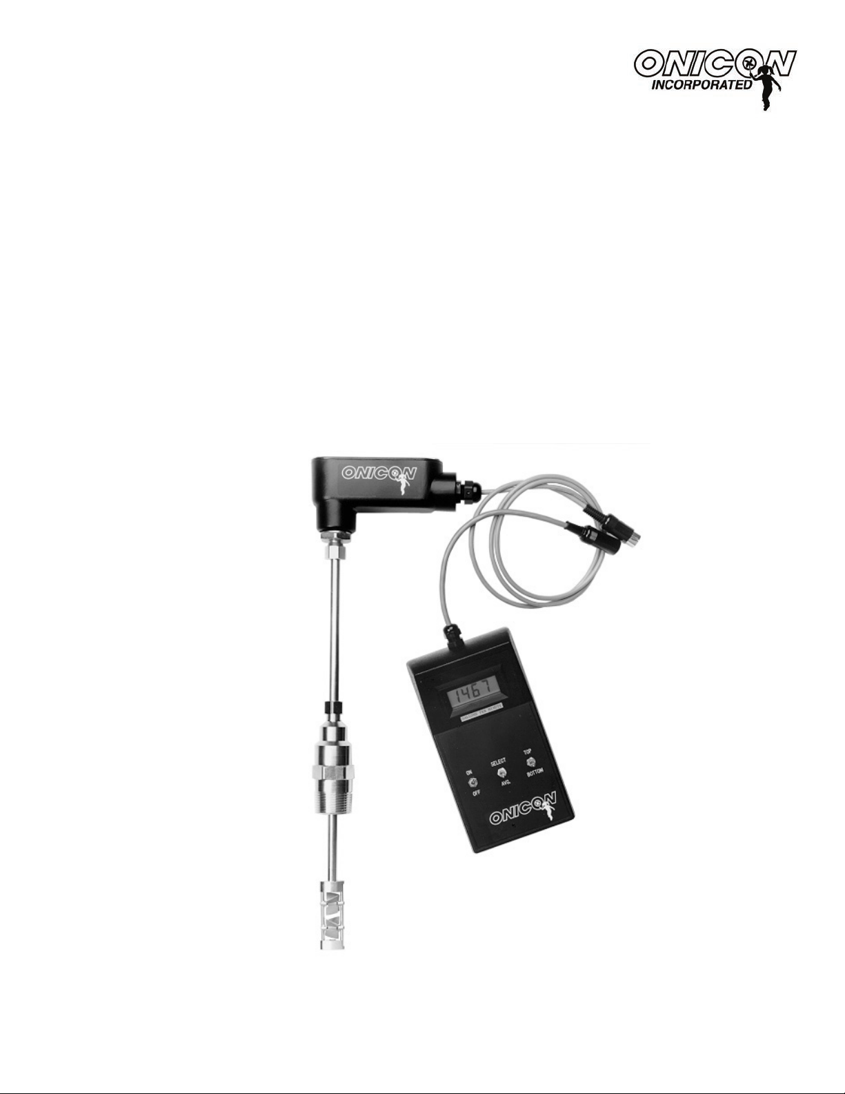
D-1400 and D-1402 Portable Metering System
Installation and Operation Guide
0722-2
11451 Belcher Road South, Largo, FL 33773 • USA • Tel +1 (727) 447-6140 • Fax (727) 442-5699
www.onicon.com • sales@onicon.com
05-14
Page 2

1 1451 Belcher Road South, Largo, FL 33773 • USA • T el +1 (727) 447-6140 • Fax (727) 442-5699 • sales@onicon.com
D-1400 Portable Metereing System Manual 05/14 - 0722-2 Page 2
Page 3

TABLE OF CONTENTS
1.0 INTRODUCTION ..................................................................................................5
1.1 Purpose of this guide ................................................................................. 5
1.2 System Description .................................................................................... 5
1.3 System Components ..................................................................................5
2.0 SYSTEM OPERATION AND SET-UP ................................................................... 7
2.1 System Operation ......................................................................................7
2.2 Initial System Set-up .................................................................................6
2.3 Basic Flow Measurement ..........................................................................7
2.4 Flow Proling Measurment ....................................................................... 7
2.5 System Storage and Maintenance Recommendations .............................. 8
2.6 Flow Meter Information ............................................................................9
3.0 INSTALLATION, REMOVAL AND ADJUSTMENT ............................................8
3.1 Site Selection .............................................................................................8
3.2 Mechanical Installation ............................................................................. 9
3.3 Insertion of the Meter ..............................................................................10
3.4 Removal of the Meter ...............................................................................14
CONDITIONS OF SALE ................................................................................................ 16
1 1451 Belcher Road South, Largo, FL 33773 • USA • T el +1 (727) 447-6140 • Fax (727) 442-5699 • sales@onicon.com
D-1400 Portable Metereing System Manual 05/14 - 0722-2 Page 3
Page 4

1 1451 Belcher Road South, Largo, FL 33773 • USA • T el +1 (727) 447-6140 • Fax (727) 442-5699 • sales@onicon.com
D-1400 Portable Metereing System Manual 05/14 - 0722-2 Page 4
Page 5
SECTION 1: INTRODUCTION
1.1 PURPOSE OF THIS GUIDE
The purpose of this guide is to provide installation procedures and basic operating and servicing
instructions for the ONICON Model D-1401 and
D-1402 Portable Metering System.
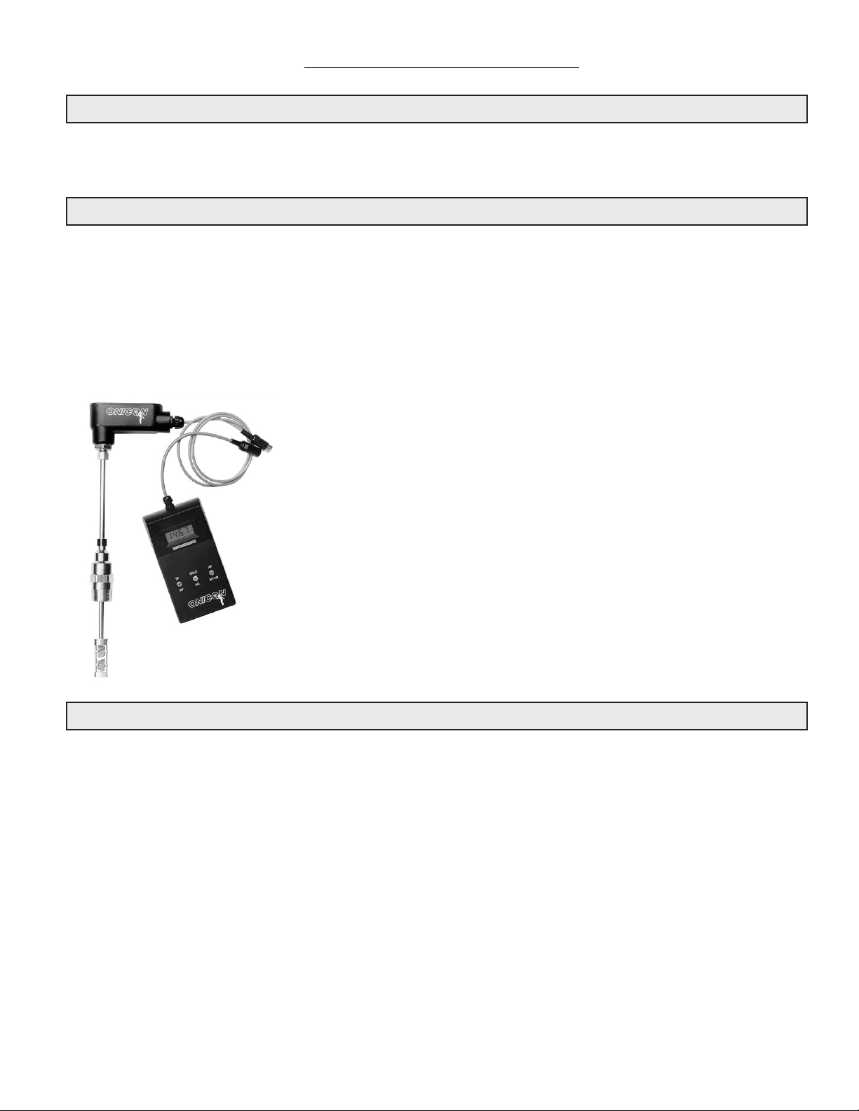
1.2 SYSTEM DESCRIPTION
The D-1401 and D-1402 Portable Metering Systems are designed to measure the ow rate of conductive liquids in multiple pipe sizes. They can also be used to perform ow proling for analysis of ow
measurement problems.
The D-1401 Portable Metering System includes a F-1100 single turbine ow meter and can be used to
measure 1.25 inch and larger pipe sizes.
The D-1402 Portable Metering System includes a F-1200 dual turbine ow meter and can be used to
measure 2.5 inch and larger pipe sizes.
The ow meter portion of the system is typically inserted into
a lled and pressurized pipe via an existing one inch minimum
diameter full port ball valve. For pipes that can be easily drained
before and after measurement, the ow meter can be inserted
into a one inch minimum diameter outlet that can accept a one
inch NPT male threaded adaptor. For lled and pressurized
pipes without installed full port valves, wet tapping installation
hardware kits are available from ONICON.
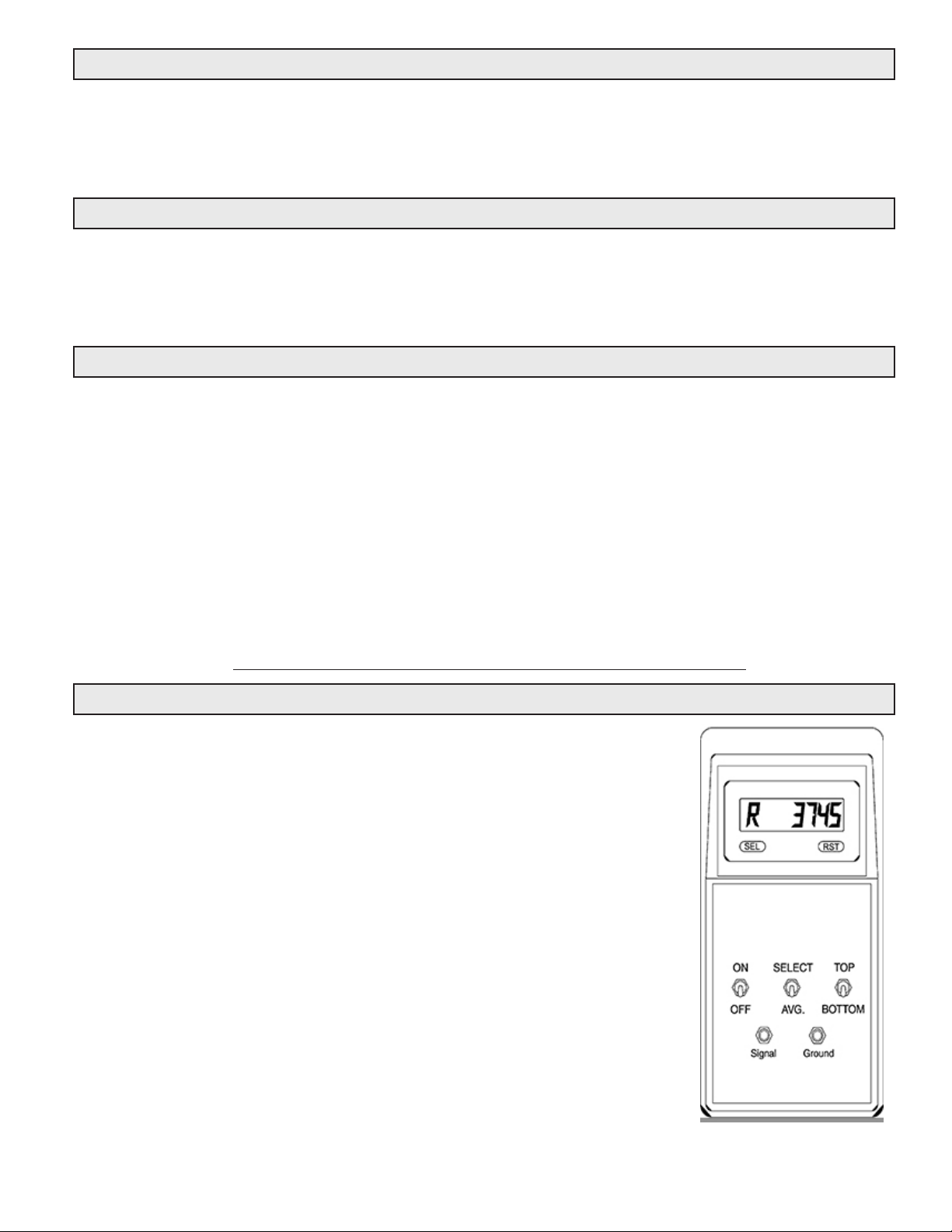
The display module includes an LCD display, control switches
and cable. A single 9 volt alkaline battery, located in the display
module battery compartment, powers the complete system,
including the ow meter.
1.3 System Components
The D-1401 Portable Metering System contains the following components:
• Model F-1100 Insertion Turbine Flow Meter
• Model D-1401 battery powered hand-held display
• Carrying case
• Owner’s manual
• Laminated conversion chart. (*Serialized for the specic F-1100 ow meter *)
The D-1402 Portable Metering System contains the following components:
• Model F-1200 Insertion Turbine Flow Meter
• Model D-1402 battery powered hand-held display
• Carrying case
• Owner’s manual
• Laminated conversion chart. (*Serialized for the specic F-1200 ow meter *)
1 1451 Belcher Road South, Largo, FL 33773 • USA • T el +1 (727) 447-6140 • Fax (727) 442-5699 • sales@onicon.com
D-1400 Portable Metereing System Manual 05/14 - 0722-2 Page 5
Page 6

GENERAL SPECIFICATIONS
ACCURACY
• ± 0.4% of reading from 3.3 to 33 ft/sec
• ± 0.8% of reading from 1 to 3.3 ft/sec
• ± 2.0% of reading from 0.4 to 1 ft/sec
SENSING METHOD
Electromagnetic sensing (no moving parts)
AVAILABLE METER SIZES
(nominal pipe diameters in inches)
1, 1½, 2, 3, 4, 6, 8, 10, 12, 14, 16, 18, 20, 24, 26, 30,
34, 36, 40, 42 & 48 (Inquire for other sizes)
LIQUID TEMPERATURE RANGES
32° to 130° F
BODY MATERIAL
Heavy duty plastic enclosure with
sliding door for battery
RATE IDICATOR
• Type: Six digit LCD with 0.46” numbers
• Calibration: Set at the factory to read turbine
frequency in Hertz. A conversion chart allows the
user to convert frequency to volumentric ow rate
(GPM) in any pipe size. Factory will set to read
GPM or any other units for particular pipe size upon
request.
• Field programming possible
• Memory: Non-volatile E2PROM memory retains
all programming parameters and count value in the
event of power interruption
POWER SUPPLY
9 Volt battery (NEDA Type 1604) in rear compartment powers the ow meter and LCD display
OUTPUT SIGNALS PROVIDED
• Isolated 4 – 20mA analog output for ow rate
• (2) Programmable pulse outputs (open collector)
AMBIENT TEMPERATURE RANGE
32° to 130° F
ELECTRICAL CONNECTIONS
Pre-wired inline cable connector for ow meter connection
Note: Specications are subject to change without
notice
1 1451 Belcher Road South, Largo, FL 33773 • USA • T el +1 (727) 447-6140 • Fax (727) 442-5699 • sales@onicon.com
D-1400 Portable Metereing System Manual 05/14 - 0722-2 Page 6
Page 7
1.4 ADDITIONAL REQUIRED HARDWARE
Flow Meter
ONICON offers a wide variety of ow meters to satisfy most liquid, gas and steam
metering applications. Please refer to ONICON’s ow meter literature, or consult
ONICON or your local representative for help in selecting the ow meter that will best
t your requirements.
1.5 WORKING ENVIRONMENT
The D-100 was designed for installation and use in typical industrial environments that are
free of corrosive liquids and fumes, direct liquid exposure, heavy condensation, temperature
extremes, direct sunlight, and vibrations. The operating ambient air temperature range is -20° F
to 140° F. Electrical power should be relatively clean, free of high frequency noise, large voltage
transients, and protected from power surges and brown-outs.
1.6 WARRANTY & SERIAL NUMBER
Warranty
ONICON’s 2-year “No-fault” warranty reduces start-up costs by extending coverage for
incidental damage during installation. Certain exclusions apply. Please refer to ONICON’s
Conditions of Sale for details.
Serial Number
The serial number of your D-100 is located outside and inside the enclosure. Also located
inside the enclosure is a label with the serial number of the associated ONICON ow
meter or sensor your D-100 was intended to be used with. The serial numbers are unique
identiers that you should have available when contacting ONICON for assistance
regarding the installation or use of this product.
SECTION: 2.0 SYSTEM OPERATION AND SET-UP
2.1 SYSTEM OPERATION
The D-1401 and D-1402 Display Module LCD display shows the ow
rate as a number representing the frequency output signal, in Hertz,
from the ow meter.
The D-1401 Display Module shows the frequency output signal of the
single turbine from the F-1100.
The D-1402 Display Module shows the averaged output from both
turbines. This system also has the capability of displaying the
individual output from the top or bottom turbine by using the
selection switches on the Display Module.
This frequency output is then converted to gallons per minute for the
pipe size being measured via the laminated conversion chart included
with the system.
Please contact ONICON to obtain conversion factors for any pipe
sizes not listed on the chart, or if you require a ow rate unit of
measure other than gallons or liters.
1 1451 Belcher Road South, Largo, FL 33773 • USA • T el +1 (727) 447-6140 • Fax (727) 442-5699 • sales@onicon.com
D-1400 Portable Metereing System Manual 05/14 - 0722-2 Page 7
Page 8

2.2 INITIAL SYSTEM SET-UP
1. Insert the ow meter into the pipe to be measured. (See manual section entitled “Flow
Meter Information” for specic information on installation procedures and recommended
insertion depths.)
2. Plug the Display module cable connector into the connector on the ow meter output cable.
3. Turn the Display module power switch to the “ON” position and verify that a number
appears on the LCD display.
2.3 BASIC FLOW MEASUREMENT
1. Turn the power switch (left) to “ON” position.
2. Set the middle switch to “AVG” and allow 45 seconds for the ow meter circuitry to
stabilize.
3. Record the average reading in Hz on the display and refer to the laminated conversion
chart to calculate the ow rate. Please note that the frequency number displayed may vary
rapidly (by as much as 10-15%) as a result of the actual ow conditions in the pipe.
4. Locate the pipe size being measured on the laminated conversion chart and determine the
“Z Factor” for gallons per minute (or liters per minute) for that pipe size.
5. Then multiply the Z factor by the average reading in Hz from step 3 to obtain the ow rate
in gallons per minute.
2.4 FLOW PROFILING MEASUREMENT
D-1401 / D-1402 Systems:
Signicant information about the nature of ow across the entire pipe diameter can be obtained by
taking ow measurements at incremental insertion depths.
Depending on the pipe size to be measured, determine an appropriate measurement increment that
will provide the required information. (For example: when measuring the ow prole of an 8 inch
pipe, measurements may be made at 1 inch increments to provide the desired prole.)
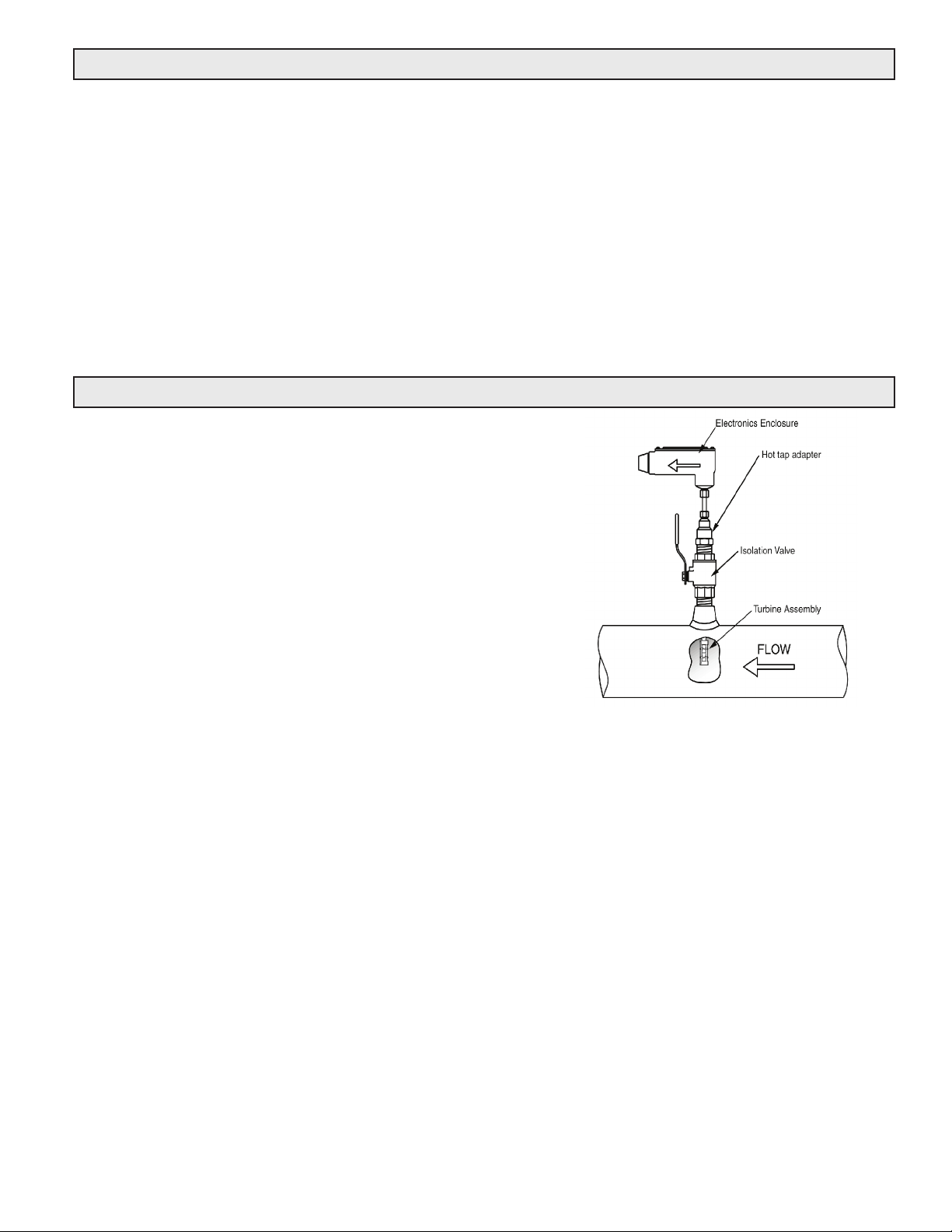
With the ow meter properly inserted in the pipe, loosen the hot tap adaptor lock nut and push
the meter into the pipe until the end of the meter touches the far pipe wall. Using this as a starting
point, pull the meter back out by the desired increment of measurement and measure the ow rate.
Repeat this process until readings have been made across the entire interior diameter of the pipe.
In large pipes where the ow meter is not long enough to touch the far pipe wall, measurements
can be made using the near pipe wall as a starting point. Push the ow meter into the pipe just
until a ow reading is obtained on the display. (For the D-1402 systems, the top turbine output can
be observed to see when it clears the pipe wall and begins to spin.) Beginning at that point, start
making measurements at the desired incremental insertion depths.
D-1402 System Only:
When using a D-1402 system, the individual top and bottom turbine frequencies can be observed
as a reference to the amount of rotational swirl that is present at each insertion depth measurement
point.
To utilize this function, set the middle switch to “SELECT”. The right switch can then be toggled
between “TOP” and “BOTTOM” to display the individual turbine frequencies.
A stable, uniform ow velocity at the measurement depth will be indicated by having the same or
very close (+/- 10%) to the same frequency reading on both the top and bottom turbine.
A signicant difference between the top and bottom turbine frequency numbers will indicate the
presence of ow turbulence and swirl at the measurement depth. The top and bottom turbines
rotate in opposite directions. Turbulence and swirl will either increase or decrease the speed of
rotation of one of the turbines and will have the opposite effect on the other turbine.
1 1451 Belcher Road South, Largo, FL 33773 • USA • T el +1 (727) 447-6140 • Fax (727) 442-5699 • sales@onicon.com
D-1400 Portable Metereing System Manual 05/14 - 0722-2 Page 8
Page 9
2.6 SYSTEM STORAGE AND MAINTENANCE RECOMMENDATION
1. Always store the system in its carrying case when not in use.
2. Before long-term storage of the system, blow all excess water from the ow meter turbine
assembly and wipe the ow meter stem assembly dry with a clean cloth. Do not put any
lubricants on the turbine assembly. Oil based lubricants will damage the ow meter’s o-ring
seals.
3. If storing the system for long periods of time, remove the 9 volt battery from the Display
Module and store it separately.
4. The ow meter’s hot tap adapter should be pushed completely down over the turbine
assembly and locked so that the turbines are protected when moving the system to a new
location or when storing the system.
5. The ow meter turbines, bearings and shafts can be cleaned using a 30 percent white
vinegar to 70 percent tap water solution. An old toothbrush can be used to lightly brush
around the bearings. Rinse with clean water and blow off excess water before storing.
2.6 FLOW METER INFORMATION
ONICON’s D-1401 / D-1402 Insertion Turbine Flow Meter measures the velocity of owing liquids by counting
the frequency at which the blades of a rotating turbine
pass a xed electrode. Circuitry within the ow meter
electronics enclosure then converts the rotational rate to
a frequency output.
1 1451 Belcher Road South, Largo, FL 33773 • USA • T el +1 (727) 447-6140 • Fax (727) 442-5699 • sales@onicon.com
D-1400 Portable Metereing System Manual 05/14 - 0722-2 Page 9
Page 10

SECTION 3.0: INSTALLATION
The D-100 should be installed by qualied individuals with knowledge and experience in the heating,
cooling, and uid metering elds. ONICON will be happy to assist with technical recommendations
1 1451 Belcher Road South, Largo, FL 33773 • USA • T el +1 (727) 447-6140 • Fax (727) 442-5699 • sales@onicon.com
D-1400 Portable Metereing System Manual 05/14 - 0722-2 Page 10
Page 11

and to provide guidance by telephone and/or email. On-site eld engineering, installation and service
are also available at an additional cost. The installer should use good trade practices and must adhere
to all state, federal and local building codes.
3.1 SITE SELECTION
Careful attention to the site selection for the system components will help the installers with the
initial installation, reduce start-up problems and make future maintenance easier. For example,
do not install the ow meter where it will be difcult for personnel to perform periodic
maintenance and calibration. When selecting a site for mounting the system components,
consider the criteria under Section 1.5 WORKING ENVIRONMENT, as well as the following:
The D-100
1 1451 Belcher Road South, Largo, FL 33773 • USA • T el +1 (727) 447-6140 • Fax (727) 442-5699 • sales@onicon.com
D-1400 Portable Metereing System Manual 05/14 - 0722-2 Page 11
Page 12

Find an easily accessible location where wire connections can be made and meter readings
can be taken from oor level. Mount the D-100 on a vibration free surface. Avoid locations
1 1451 Belcher Road South, Largo, FL 33773 • USA • T el +1 (727) 447-6140 • Fax (727) 442-5699 • sales@onicon.com
D-1400 Portable Metereing System Manual 05/14 - 0722-2 Page 12
Page 13

such as the plenum of a fan coil, heat exchanger or any housing that may contain electric
motors or other strong sources of electrical interference.
The Flow Meter
Choose the location with the longest straight run of unobstructed pipe. Please refer to the
ow meter installation manual for specic information regarding the straight run
requirements for the ow meter used with this display.
3.2 MECHANICAL INSTALLATION
Find an easily accessible location where electrical connections can be made and meter readings
can be taken from the oor level. Mount the display on a vibration free surface. Avoid sites such
as the plenum of a fan coil, heat exchanger, or other housings containing motors.
3.3 ELECTRICAL INSTALLATION
The electrical installation of this product must comply with all federal, state and local building
codes. Connect and re-verify all input, output, network interface and safety earth wiring
connections prior to connecting power.
The drawing below shows where signal, power and earth connections are made on the mother
board located inside the D-100 enclosure. Network and digital pulse input connections are
made on the network interface board (not shown). Refer to section 3.3.1 for detailed information
on connecting ow meters, sensors, output signal and power connections.
3.3.1 Input Signal Connections from Flow Meter
1 1451 Belcher Road South, Largo, FL 33773 • USA • T el +1 (727) 447-6140 • Fax (727) 442-5699 • sales@onicon.com
D-1400 Portable Metereing System Manual 05/14 - 0722-2 Page 13
Page 14

1 1451 Belcher Road South, Largo, FL 33773 • USA • T el +1 (727) 447-6140 • Fax (727) 442-5699 • sales@onicon.com
D-1400 Portable Metereing System Manual 05/14 - 0722-2 Page 14
Page 15

1 1451 Belcher Road South, Largo, FL 33773 • USA • T el +1 (727) 447-6140 • Fax (727) 442-5699 • sales@onicon.com
D-1400 Portable Metereing System Manual 05/14 - 0722-2 Page 15
Page 16

H1
1
Earth Connection
1/4 AMP
F1
G
G
D3
J2-12
D4
20075-50 REV. A
G
+24
+15
60HZ
J2-1
10
1
5
H3
R7
LED1
J1
R1
D1
D2
T1
VAR1
TB1
NEUTRALF124V
AMP
TB1
24V NEUTRAL
OHM 5%
3W
Input Power Connection
1 1451 Belcher Road South, Largo, FL 33773 • USA • T el +1 (727) 447-6140 • Fax (727) 442-5699 • sales@onicon.com
D-1400 Portable Metereing System Manual 05/14 - 0722-2 Page 16
Page 17

GAL X 100
1 1451 Belcher Road South, Largo, FL 33773 • USA • T el +1 (727) 447-6140 • Fax (727) 442-5699 • sales@onicon.com
D-1400 Portable Metereing System Manual 05/14 - 0722-2 Page 17
Page 18

1 1451 Belcher Road South, Largo, FL 33773 • USA • T el +1 (727) 447-6140 • Fax (727) 442-5699 • sales@onicon.com
D-1400 Portable Metereing System Manual 05/14 - 0722-2 Page 18
Page 19

4.6 COMMISSIONING
pp
p
;
g
y
d
gy (
Upon initial installation, it is strongly recommended that both the D-100 and its associated ow
meter be commissioned to ensure that they are properly installed and functioning correctly.
This process involves verifying the mechanical installation, measuring ow signals and then
comparing these measurements to the specied installation and operating parameters listed on
the certicate of calibration provided with the display. The data collected during this initial
commissioning process will then serve as baseline data for periodic revalidation of the meter
operation.
INTEGRATED D-100 DISPLAY
COMMISSIONING PROCEDURE
Please read all installation instructions carefully before
proceeding. Wiring diagrams are located in this manual.
Use the display Certicate of Calibration to verify that
the specied installation & operating parameters match
the actual conditions at the location where the display
is installed. A worksheet for checking these steps and
recording measured values is located on the following
page.
METER INFORMATION
Meter Tag:
BTU Meter Model: SYSTEM-30
Serial No: 134036
SPECIFIED INSTALLATION & OPERATING PARAMETERS
Pipe Information: 1 Inch Copper Tube
Design Maximum Flow Rate: 40.0 GPM
Design Supply Temperature: MODE 1: 45°F
Design Return Temperature: MODE 1: 55°F
Fluid: 25% Ethylene Glycol
Fluid Specific Heat: 0.885 BTU/lb°F
Fluid Density: 65.06 lb/ft³
CONFIGURATION DATA
Enclosure Type:
Input Supply Voltage: 24 AC/DC
Thermowell Type:
Calibrated By: Date: 09/01/2004
ONICON Incorporated certifies that the flow and temperature sensors provided with this Btu meter have been individually calibrated based on the
a
CERTIFICATE OF CALIBRATION
Shane Hamilton
rovided above
standards directl
lication specific data
1500 North Belcher Road, Clearwater, Florida 33765 Tel (727) 447-6140 Fax (727) 442-5699
usin
traceable to the U.S. National Institute of Standards an
CALIBRATION AND PROGRAMMING DATA
Firmware Version: CFM4.6S30
Communications Protocol:
Device Network Address:
Flow Sensor MF Code: 547.500
Programmed Units & Multipliers:
Energy Total: BTU x 1K Energy Rate: BTU/HR x 1K
Flow Total: GAL x 10 Flow Rate: GPM x 1
Temperature: °F
Damping: 5
Pulse Duration: 500 ms
Supply Temperature Slope: 9.969 Offset: -0.870
Return Temperature Slope: 10.004 Offset: -0.130
OUTPUT SIGNAL SCALING
Energy Total(s): 1 Pulse = BTU x 1K
Flow Rate: NA
Energy Rate: NA
Supply T: NA
Return T: NA
Delta T: NA
Technolo
N.I.S.T.).
1. Conrm that the D-100 is being
installed with the correct ow meter
and any optional sensors.
2. Conrm that the D-100 is being
installed in accordance with
Sections 1.5 and 3.1 of this manual.
Check the label inside the front cover of the D-100 and conrm that the
serial numbers match the serial numbers of the ow meter and any optional
sensors being used.
Conrm that the installation location is not in direct sunlight and is
removed from sources of strong electrical interference. The display should
be mounted on a vibration-free surface where it will be protected against
spraying, splashing and the seepage of water.
3. Conrm the pipe diameter and pipe
material.
Conrm that the ow meter is tagged for the pipe diameter and material in
which it is to be installed and that this information matches the information
provided on the display certicate of calibration. When in doubt, measure
the circumference of the pipe.
Pipe O.D. = (circumference / 3.14) – (insulation thickness x 2)
4. Conrm that the ow meter installation
conforms to the requirements specied
in the ow meter installation manual.
Verify that the ow meter is installed in a location with enough straight
unobstructed run upstream and downstream of the pipe. Also verify that
the ow meter is properly oriented with respect to ow direction, and for
insertion meters ensure that the meter is installed to the correct insertion
depth.
5. Conrm that any optional sensors are
properly installed.
Verify that any optional sensors connected to the D-100 are installed in
accordance with the manufacturer’s installation instructions. Also conrm
that the sensor output matches the information shown on the D-100 C of C.
6. Conrm that the correct supply voltage
has been provided.
Verify and measure the AC input voltage to the display.
Input voltages should be within the following ranges.
24VAC: 20 – 28VAC
24VAC when connected to an F-3500 and the D-100 is equipped with a
multi-analog board: 21.6 – 28VAC
120VAC: 108 - 132 VAC
230VAC: 207 - 253 VAC
In order to proceed with the following steps, the display, ow meter and optional sensors must be operating and there must
be ow in the pipes. Flow signal readings should be taken while holding the ow rate constant, if possible.
7. Select the ow rate page on the D-100
front panel display.
Scroll through the D-100 display pages and select the ow rate page. Verify
that the engineering units and multiplier shown match those on the C of C.
8. Note and record the ow reading. Note the displayed ow rate and conrm that it is within the expected
range. For D-100 displays connected to ow meters with integral displays,
conrm that the ow readings shown on the two displays agree. Record the
ow rates.
1 1451 Belcher Road South, Largo, FL 33773 • USA • T el +1 (727) 447-6140 • Fax (727) 442-5699 • sales@onicon.com
D-1400 Portable Metereing System Manual 05/14 - 0722-2 Page 19
Page 20

9. For ow meters that provide a
frequency output, measure and
record output(s). Compare calculated
vs. displayed ow rates.
(F-1200 or FB-1200 only).Conrm both
turbines produce pulses
10. Compare and record the displayed values with those shown on the building
control system.
End of standard commissioning. Please contact ONICON if any questions arise.
The average frequency output signal is a 0-15 VDC pulsed output
ranging up to 200 Hz and must be measured with a frequency counter or
oscilloscope. Measure DC Frequency (Hz) at T4 from terminal 6(+) to 7(-).
GPM = Frequency in Hz X 60 X Meter Factor in ppg (refer to calibration tag
for meter factor)
For the F-1200 or FB-1200 Dual Turbine model, also measure and record
the top and bottom turbine signals.
Top Turbine: T4-12(+) to T4-2(-) Bottom Turbine: T4-13(+) to T4-2(-)
Also measure DC volts on same terminals. 5 to 7 VDC is normal for a
spinning turbine, 0 or 14+ VDC indicates a stopped turbine. (1 to 4 VDC
could indicate a problem.)
Scroll through the D-100 menu pages and conrm that the rate and total
current values and engineering units shown agree with the information
shown on the building control system display. Record the results.
COMMISSIONING WORKSHEET
Please read all installation instructions carefully prior to proceeding with these steps. Wiring
diagrams are located in this manual. Use the following worksheet for checking off the
commissioning steps and recording measured values.
Step Test/Measurement D-100 S/N: D-100 S/N: D-100 S/N:
1. Conrm and record
serial number(s)
Flow meter:
Sensor(s):
Flow meter:
Sensor(s):
Flow meter:
Sensor(s):
2. Proper installation site
selection (Y / N)
3. Record pipe diameter
4. Record number of
unobstructed upstream/
downstream pipe
diameters
5. Sensor(s)properly
installed (Y / N)
6. Record supply voltages
7. Verify that engineering
units & multipliers match
(Y/N)
8. Record ow rate and
total(s)
9. Record actual and
calculated values
10. Record displayed values D-100:
Flow rate:
Mode 1 total:
Mode 2 total:
Actual:
Calculated:
Flow rate:
Mode 1 total:
Mode 2 total:
Actual:
Calculated:
D-100:
Flow rate:
Mode 1 total:
Mode 2 total:
Actual:
Calculated:
D-100:
System:
System:
System:
1 1451 Belcher Road South, Largo, FL 33773 • USA • T el +1 (727) 447-6140 • Fax (727) 442-5699 • sales@onicon.com
D-1400 Portable Metereing System Manual 05/14 - 0722-2 Page 20
Page 21

SECTION 5.0: DIAGNOSTICS
i
i
5.1 DIAGNOSTICS
The ONICON D-100 display is programmable. Factory programmed settings provide rate and
total values in accordance with the customer’s application data. Refer to the D-100 calibration
sheet for a complete listing of factory settings. These settings may be reviewed and changed with
assistance from ONICON factory service personnel. The display is also equipped with diagnostic
indicator lights and self diagnostic test signals that conrm the operation of the microprocessor
and its input circuitry. Please contact the ONICON factory service personnel if any of the
diagnostic lights or test signals listed below indicates a potential problem with the operation of
the Btu meter.
5.1.1 Diagnostic Lights
Low Voltage Power Supply
Located on the power supply board inside the System-10 BTU Meter (refer to page A-3),
these two LEDs will be illuminated when the positive and negative ve volt supplies
are present.
Liquid Flow
Located just above the power supply on the motherboard (refer to page A-1) is the ow
indicator LED. The LED will ash at a rate that is proportional to the liquid ow rate.
An unlit LED indicates no ow signal.
5.1.2 Flow Test Signals
Located on the right side of the motherboard (refer to A-1) immediately above the power
supply board is a three position slide switch used to test the ow input. When the switch
is in the top position, the input is connected to the ow meter. When the switch is in the
middle position, the input is connected to two test terminals used to apply a variable
frequency to simulate ow. When the switch is in the bottom position, the input is
connected to a 50/60 Hz signal that simulates a xed ow rate. Refer to the calibration
certicate to determine the correct display reading when operating in the 50/60 Hz test
mode.
IMPORTANT NOTE
The second line of the display will alternate between TEST MODE and the normal display of
engineering units and multipliers whenever the ow test switch is in the TEST or 60 Hz positions.
IMPORTANT NOTE
After operating for ve minutes in either the TEST or 60 Hz mode, the displayed ow and energy
rate will be disabled, and the meter will report a zero ow rate and a zero energy rate to the
network. The meter will remain in this state until the switch is set to RUN.
5.1.3 Ai3 & Ai4 Test Signals
As you are facing the component side of the processor board, the Ai3/Ai4 Test push button
is along the top edge of the board just to the left of the at ribbon cable. It is labeled TEMP
TEST. When pressed, a xed current will be applied to each sensor input. Both Ai3 and
Ai4 will produce an output equal to 37.5% of their programmed full scale output. This test
conrms the operation of the D-100 processor board input circuitry for Ai3 and Ai4.
1 1451 Belcher Road South, Largo, FL 33773 • USA • T el +1 (727) 447-6140 • Fax (727) 442-5699 • sales@onicon.com
D-1400 Portable Metereing System Manual 05/14 - 0722-2 Page 21
Page 22

5.2 TROUBLESHOOTING GUIDE FOR D-100 DISPLAY
NOTE: Also refer to the COMMISSIONING GUIDE located on the preceding pages.
Reported Problem Possible Solutions
Flow rate is indication zero ow.
(When uid is owing in the pipe.)
• Verify that the correct supply voltage is
present at the ow meter power input.
• Verify that the ow meter signal outputs
are properly wired to the display.
• For insertion meters, verify that the
meter is correctly inserted and parallel
with the pipe.
• For turbine meters, verify that the turbines
are not clogged with debris.
• Re-conrm that there is really ow in the
pipe.
Displayed ow rate is too high or too low. • Verify that the serial number of the ow
meter matches the serial number shown
on the label inside the D-100 front cover.
• Verify that the correct supply voltage is
present at the ow meter power input.
• Verify that the pipe diameter matches the
diameter shown on the calibration
certicate and on the ow meter tag.
• For insertion meters, verify that the
meter is correctly inserted and parallel
with the pipe.
• For turbine meters, verify that the turbines
are not clogged with debris.
Ai3 and/or Ai4 sensor values are too high or
too low.
• Verify that the sensor scaling matches
that programmed values shown on the
label inside the D-100 front cover and on
the calibration certicate.
• Conrm that the control system is
correctly scaled.
Data is not available at the control system. • Verify network addresses are properly
programmed into the D-100.
• If applicable, verify the Baud rate.
• Check the polarity of the network
connections.
For technical assistance, contact ONICON Incorporated at (727) 447-6140.
1 1451 Belcher Road South, Largo, FL 33773 • USA • T el +1 (727) 447-6140 • Fax (727) 442-5699 • sales@onicon.com
D-1400 Portable Metereing System Manual 05/14 - 0722-2 Page 22
Page 23

APPENDIX
A-1 D-100 DISPLAY MOTHER BOARD
A-2 D-100 PROCESSOR BOARD
A-3 D-100 POWER SUPPLY BOARD
A-4 D-100 ANALOG OUTPUT BOARD
A-5 D-100 ANALOG OUTPUT BOARD With 4 Analog Outputs
A-6 CONDITIONS OF SALE
1 1451 Belcher Road South, Largo, FL 33773 • USA • T el +1 (727) 447-6140 • Fax (727) 442-5699 • sales@onicon.com
D-1400 Portable Metereing System Manual 05/14 - 0722-2 Page 23
Page 24

D-100 DISPLAY MOTHER BOARD
Pulse and analog output connections
OUTPUTS
TOTALIZER OUTPUT
TOTALIZER OUTPUT
H1
1
H2
1
5
10
15
20
25
30
H3
1
5
10
15
20
25
30
MODE 1
(+)
MODE 2
(-)
MODE STATUS
CHANNEL A
ANNALOG OUTPUT
CHANNEL B
ANALOG OUTPUT
CHANNEL C
ANALOG OUTPUT
CHANNEL D
ANALOG OUTPUT
ALARM
OUTPUT
S1
RUN
+
-
+
-
+
-
+
-
LED1
T1
1
2
3
4
5
6
7
8
9
10
11
12
13
14
15
16
17
18
FLOW
INDICATOR
T3
T4
10
11
12
13
T5
TEST
D1
D2
+ -
15 V PULSE
D3
D4
35
40
45
35
40
45
60 HZ
T1
ANALOG INPUTS
1
2
3
4
5
SIGNAL
REFERENCE
SIGNAL
REFERENCE
SHIELDS
FLOW METER INPUTS
1
2
3
4
5
6
7
8
9
1
2
3
4
5
6
J2-12
24 VDC SUPPLY +
SUPPLY COMMON SHIELD
4-20mA +
4-20mA FREQUENCY +
FREQUENCY DIRECTION +
DIRECTION ALARM +
ALARM TOP TURBINE
BOTTOM TURBINE
AUXILIARY FLOW METER SIGNALS
4-20mA 0-10 VDC +
ANALOG COMMON -
ISOLATED ANALOG COMMON -
SCALED +
SCALED -
G
G
+24
+15
10
Ai3Ai4
Ai2
Di2
G
60HZ
J2-1
1
5
H3
Ai3 & Ai4 analog
input connections
Ai2 / Di2
Flow meter
connections
R7
C5
D5
C4
R1
R5
U2
R3
LED1
J1
ONICON INC.
20036 Rev. D
PROCESSOR BOARD
VAR1
F1
1/4 AMP
TB1
120VAC
NEUTRAL
20075-50 REV. A
EXPANSION SLOTS FOR:
1. COMMUNICATIONS BOARD
2. ANALOG OUTPUT BOARD
C6
D6
C1
C2
U1
C3
R1
POWER SUPPLY
*Standard: 24 VAC
Optional: 120 or 230 VAC
1 1451 Belcher Road South, Largo, FL 33773 • USA • T el +1 (727) 447-6140 • Fax (727) 442-5699 • sales@onicon.com
D-1400 Portable Metereing System Manual 05/14 - 0722-2 Page A-1
Page 25

D-100 PROCESSOR BOARD
RESET
TEMP TEST
PROG MODE
ENABLE
DEVICE ADDRESS
PROGRAM ENABLE
SERIAL
COMM
1 1451 Belcher Road South, Largo, FL 33773 • USA • T el +1 (727) 447-6140 • Fax (727) 442-5699 • sales@onicon.com
D-1400 Portable Metereing System Manual 05/14 - 0722-2 Page A-2
Page 26

D-100 POWER SUPPLY BOARD
D1
D2
T1
D3
D4
J2-12
+24
+15
10
G
G
G
60HZ
J2-1
5
1
H3
Fuse
Holder
VAR1
1/4 AMP
TB1
F1
24V
NEUTRAL
VAC CONNECTION
R1
20075-50 REV. A
C3
C1
U1
C6
D6D5
C2
R5
R1
C5
C4
J1
R7
U2
R3
LED1
FUSES
24 VAC 120 VAC 230 VAC
3AG 3AG 3AG
1 AMP 1/4 AMP 1/8 AMP
250 VOLT 250 VOLT 250 VOLT
SLO-BLO SLO-BLO SLO-BLO
1 1451 Belcher Road South, Largo, FL 33773 • USA • T el +1 (727) 447-6140 • Fax (727) 442-5699 • sales@onicon.com
D-1400 Portable Metereing System Manual 05/14 - 0722-2 Page A-3
Page 27

D-100 ANALOG OUTPUT BOARD
ISO ANALOG OUT
20039_5_REV B
C10
C20
C21
45 40 35 30 25 20 15 10 5 1
U20
C23
U10
U11
U12
R3
C22
U6
R1
R2
R8
U14
C8
D1
C15
C9
T2
C12
U17
C24
C13
Q1
C7
C3
C11
R6
R7
R5
U8
C1
C14
C18
H1
C2
H2
U16
U15
FLOW
DELTA T
BTU RATE
LO TEMP
HI TEMP
C16
C17
D7
D5
D6
R14
R9
R15
R10
D4
U9
Q2
H3
R11
R13
SPAN
ZERO
0-10 VDC
4-20 mA
1 1451 Belcher Road South, Largo, FL 33773 • USA • T el +1 (727) 447-6140 • Fax (727) 442-5699 • sales@onicon.com
D-1400 Portable Metereing System Manual 05/14 - 0722-2 Page A-4
Page 28

D-100 ANALOG OUTPUT BOARD
with 4 analog outputs
4 CH. Analog
ONICON INC. 20049 Rev. A
U1
151015202530354045
H1
R52
R1
C1
R3
D3
C6
U2
R4
D5
R6
C18
U3
Q2 Q1
C8
C10
C7
C2
C5R5
C9
C13
C15
D1
U4
C16
C4
U5
D2
C12
D7D6
C11
C14
U20
R50
C37
R51
C36
U19
J5
R2 R7
Hi Temp
R8C3
Flow Rate
C17
U6
D8
C19
R12
R10
R11
R14
C20
R11
Lo Temp
Flow Rate
C22
R17
R18 R19
U9
J6
D14
C23
R23
R21
R22
R25 R24
C24
J7
J8
R28
BTU Rate
R29
R30
Flow Rate
U12
C26
R39
Delta T
R40
R41
Flow Rate
U15
C30
C28
D18
C27
R34
R32
R33
R34 R35
D22
C31
R45
R43
R44
C32
R47
R46
U18
D21D20
D10
D4
D12
D13
D16
D17
C34
C35
U7
U10
U13
U16
C25
C29
C33
C21
D9
R27
D11
D15
D19
D26
R16
D23
R38
D24
R49
Q3
Q4
D25
Q5
Q6
T1
R9
R15
0-10V
R20 R26
R31
R37
R42 R48
0-10V
0-10V
0-10V
0-5V
0-5V
0-5V
0-5V
CH A.
SPAN
ZERO
J1
4-20mA
CH B
SPAN
ZERO
J2
4-20mA
CH C
SPAN
ZERO
J3
4-20mA
CH D
SPAN
ZERO
J4
4-20mA
1 1451 Belcher Road South, Largo, FL 33773 • USA • T el +1 (727) 447-6140 • Fax (727) 442-5699 • sales@onicon.com
D-1400 Portable Metereing System Manual 05/14 - 0722-2 Page A-5
Page 29

CONDITIONS OF SALE
1. ACCEPTANCE: The following Conditions of Sale apply to all sales of ONICON’s products. These provisions shall apply even if ONICON fails to
object to provisions appearing on, incorporated by, referenced in, or attached to Buyer’s purchase order form. Buyer’s acceptance of delivery of
ONICON’s products constitutes its acceptance of these Conditions of Sale.
2. DELIVERY AND TITLE: All product shipments are Ex Works and title passes to the Buyer at the time ONICON delivers the
merchandise to the carrier. Risk of loss or damage to the product passes to the Buyer at the time ONICON delivers the product to the carrier.
The Buyer immediately upon receipt should inspect all shipments, and should there be any evidence of damage or loss in transit, Buyer must le
claims or tracers upon carrier. ONICON will assist in tracing shipments upon request.
3. LIMITED WARRANTY: ONICON warrants that for a period of two (2) years following the date of original shipment of an ONICON product: (i) the
product will conform to ONICON’s standard written specications applicable to such product in effect on the date of Buyer’s order, or as modied
by ONICON’s quotation or Buyer’s purchase order accepted by ONICON, (ii) the product will be free from defects in workmanship, and (iii) that
ONICON has title to the product prior to shipment to the Buyer; provided, however, that the warranties provided herein shall be void and may not
apply in the event Buyer misuses or damages a product, including, but not limited to, any use by the Buyer of a product for an application other
than one of a type approved by ONICON. ONICON’s sole liability and Buyer’s sole remedy for any breach of the foregoing warranty is for
ONICON to repair or replace, at ONICON’s option, any defective product that is returned to ONICON during the warranty period. EXCEPT AS
MAY BE SPECIFICALLY AGREED BY ONICON IN WRITING IN RELATION TO EACH SALE, NO OTHER WARRANTIES SHALL APPLY,
WHETHER EXPRESSED, IMPLIED OR STATUTORY, AND THERE SHALL BE NO IMPLIED WARRANTIES OF MERCHANTABILITY AND
FITNESS FOR A PARTICULAR PURPOSE.
4. REMEDIES: ONICON’s OBLIGATION UNDER THE FOREGOING WARRANTIES IS LIMITED SOLELY TO REPAIR OR REPLACEMENT, AT
ONICON’s OPTION, OF DEFECTIVE OR NONCONFORMING PRODUCTS. ONICON SHALL NOT BE LIABLE FOR CONSEQUENTIAL,
INDIRECT, PUNITIVE, INCIDENTAL, OR SPECIAL DAMAGES WHETHER FOUND ON CONTRACT, TORT OR ANY OTHER THEORY OF LAW.
No products shall be returned to ONICON without its prior consent and transportation and insurance costs shall be prepaid. Any repair or
replacement of ONICON’s products under the foregoing warranty will be at no charge to the Buyer provided such repair is done at the ONICON
factory or authorized service center. ONICON products that are repaired or replaced under this warranty will be returned to Buyer via the same
method of shipment use to return the product to ONICON. Repair or replacement of ONICON products is conditioned upon ONICON’s
acknowledgement of any alleged defect or nonconformance during the warranty period and issuance of a Return Authorization number. All
product returns must reference the Return Authorization number on the outside of the shipping carton and on any paperwork referencing the
return.
5. PRICES AND PAYMENT TERMS: The prices set forth in the most recent quote or acknowledgement as applicable, supersede all previous prices
or quotations. All quotations are subject to change or withdrawal without notice except as may be specically noted on the face of the quotation.
The prices shown do not include sales, excise or government charges payable by ONICON to Federal, State, or local authority. Any such tax or
charge now or hereafter imposed upon the sale or shipment of the products under this contract will be added to the purchase price. Buyer agrees
to reimburse ONICON for such tax or charge or provide ONICON with an acceptable exemption certicate. Payment of invoices will be due 30
days from the date of shipment of the products contained therein. In the event that payment of an invoice is not received by the invoice due date,
ONICON will assess a late fee not to exceed 1.5% per month or 18% per year, or the maximum allowable by law whichever is lower.
6. CANCELLATION: Buyer may cancel its order, or any part of it, by sending written notice of cancellation to ONICON and paying a reasonable
cancellation fee as determined by ONICON. The reasonable cancellation fee will reect, among other factors, the expenses already incurred and
commitments made by ONICON, sales and administrative costs and prot as determined by ONICON. If Buyer received a reduced price based on
the quantity of products ordered, but has not purchased the applicable quantity at the time of cancellation, Buyer will pay the price it would have
paid had ONICON’s sale price been based on the quantity actually purchased.
7. CHANGES: If Buyer makes any changes in its drawings, designs, or specications applicable in any contract with ONICON that cause an increase
or decrease in the cost of performance of the contract, or if such changes result in rework or obsolescence, an equitable adjustment shall be made
to the contract. Such changes are subject to ONICON’s prior written consent.
8. EXCUSABLE DELAY: ONICON shall under no circumstance be responsible for failure to ll any order or orders when due to: res, oods, riots,
strikes, freight embargoes or transportation delays, shortage of labor, inability to secure fuel, material supplies, or power at current price or on
account of shortages thereof, acts of God or of the public enemy, any existing or future laws or acts of the Federal or State Government (including
specically, but not exclusively, and orders, rules or regulations issued by any ofcial or agency of any such government) affecting the conduct of
ONICON’s business with which ONICON in its judgment and discretion deems it advisable to comply as a legal or patriotic duty, or due to any
cause beyond ONICON’s reasonable control.
9. PATENTS: ONICON shall defend all suits or proceedings brought against Buyer or its customers arising from claimed infringements of any
patent, trademark, service mark or copyright for any product furnished by ONICON and shall indemnify it against all costs, fees, and damages on
the condition Buyer promptly noties ONICON in writing and provides information and assistance to enable ONICON to conduct the defense,
provided that ONICON shall have no such obligation in case of infringement resulting from ONICON’s conformance to special requirements of
Buyer. If ONICON is not able to settle any such suit or proceeding on acceptable terms, ONICON may, at its option, require return of the
infringing product and refund the purchase price to Buyer less a reasonable allowance for depreciation or use.
10. FAIR LABOR STANDARDS ACT: ONICON represents that all products delivered under this contract are furnished in accordance with the
applicable provisions of the Fair Labor Standards Act as amended.
11. APPLICABLE LAW: This document and any resulting contract shall be governed by and construed in accordance with the laws of the State of
Florida. The courts of the State of Florida and the federal courts located in Florida shall have jurisdiction and venue with respect to litigation to
this contract. In the event of litigation, the prevailing party shall be entitled to recover attorney’s fees and costs from the non-prevailing party,
including appellate attorney’s fees.
12. MODIFICATIONS: These Conditions of Sale along with the prices, quantities, delivery schedules and other provisions and instructions in
applicable quotations by ONICON or Buyer’s purchase orders accepted by ONICON shall constitute the entire agreement between ONICON and
1 1451 Belcher Road South, Largo, FL 33773 • USA • T el +1 (727) 447-6140 • Fax (727) 442-5699 • sales@onicon.com
Buyer pertaining to any resulting contract. They can be modied only in writing.
D-1400 Portable Metereing System Manual 05/14 - 0722-2 Page A-6
 Loading...