

Page 1
D-100 FLOW DISPLAY with NETWORK INTERFACE
Installation and Operation Guide
11451 Belcher Road South, Largo, FL 33773 • USA • Tel +1 (727) 447-6140 • Fax +1 (727) 442-5699
0634-14 / 18340
www.onicon.com • sales@onicon.com
10-14
Page 2

11451 Belcher Road South, Largo, FL 33773 • USA • Tel +1 (727) 447-6140 • Fax +1 (727) 442-5699 • sales@onicon.com
D-100 Flow Display Manual 10/14 - 0634-14 / 18340 Page 2
Page 3

TABLE OF CONTENTS
1.0 INTRODUCTION ..................................................................................................5
1.1 Purpose of this guide ................................................................................. 5
1.2 Typical D-100 Network Interface Module .................................................5
1.3 Standard Features and Specications .......................................................5
1.4 Additional Hardware Required ................................................................. 7
1.5 Working Environment ...............................................................................7
1.6 Warranty & Serial Number ........................................................................7
2.0 UNPACKING ......................................................................................................... 7
2.1 Checking that you have received everything ............................................7
3.0 INSTALLATION ....................................................................................................8
3.1 Site Selection .............................................................................................8
3.2 Mechanical Installation ............................................................................. 9
3.3 Electrical Installation ...............................................................................10
3.3.1 Input Signal Connections from Flow Meter ................................10
3.3.1.1 ONICON Turbine Flow Meters ........................................ 11
3.3.1.2 ONICON F-3500 Flow Meters .........................................12
3.3.1.3 ONICON FB-3500 Flow Meters ....................................... 12
3.3.1.4 ONICON F-3100 and F-3200 Flow Meters ...................... 13
3.3.1.5 ONICON F-2500 Flow Meters .........................................14
3.3.1.6 ONICON F-2600 & 2700 Series Flow Meters .................. 15
3.3.1.7 ONICON F-4200 Series Flow Meters ..............................16
3.3.1.8 ONICON F-5100 Series Flow Meters ..............................17
3.3.1.9 ONICON F-5200 Series Flow Meters ..............................18
3.3.2 Frequency Pulse Flow Input (Di2) ...............................................19
3.3.3 Analog Flow Input (Ai2) ...............................................................19
3.3.4 Directional Contacts ......................................................................19
3.3.5 Analog Inputs (Ai3 & Ai4) ............................................................ 19
3.3.6 Digital Pulse Input (Di3) ............................................................... 19
3.3.7 Totalizer Outputs and Mode Status ..............................................20
3.3.8 Isolated Analog Outputs ............................................................... 20
3.3.9 Input Power ................................................................................... 21
4.0 D-100 START-UP AND COMMISSIONING ....................................................... 23
4.1 Display and Keypad .................................................................................23
4.2 Processor Start-up .................................................................................... 23
4.3 Units and Multipliers ..............................................................................24
4.4 Analog Outputs ........................................................................................ 24
4.5 Enabling / Disabling Front Panel Reset ..................................................24
4.6 Commissioning ........................................................................................25
5.0 DIAGNOSTICS ....................................................................................................27
5.1 Diagnostics ............................................................................................... 27
5.1.1 Diagnostic Lights ...........................................................................27
5.1.2 Flow Test Signals .......................................................................... 27
5.1.3 Ai3 & Ai4 Test Signals .................................................................. 27
5.2 Troubleshooting ....................................................................................... 28
11451 Belcher Road South, Largo, FL 33773 • USA • Tel +1 (727) 447-6140 • Fax +1 (727) 442-5699 • sales@onicon.com
D-100 Flow Display Manual 10/14 - 0634-14 / 18340 Page 3
Page 4

APPENDIX
A-1 D-100 DISPLAY MOTHER BOARD
A-2 D-100 PROCESSOR BOARD
A-3 D-100 POWER SUPPLY BOARD
A-4 D-100 ANALOG OUTPUT BOARD
A-5 D-100 ANALOG OUTPUT BOARD With 4 Analog Outputs
A-6 CONDITIONS OF SALE
11451 Belcher Road South, Largo, FL 33773 • USA • Tel +1 (727) 447-6140 • Fax +1 (727) 442-5699 • sales@onicon.com
D-100 Flow Display Manual 10/14 - 0634-14 / 18340 Page 4
Page 5
SECTION 1: INTRODUCTION
1.1 PURPOSE OF THIS GUIDE
The purpose of this guide is to provide installation and commissioning procedures and basic
operating and servicing instructions for the ONICON D-100 Flow Display and Network
Interface Module.
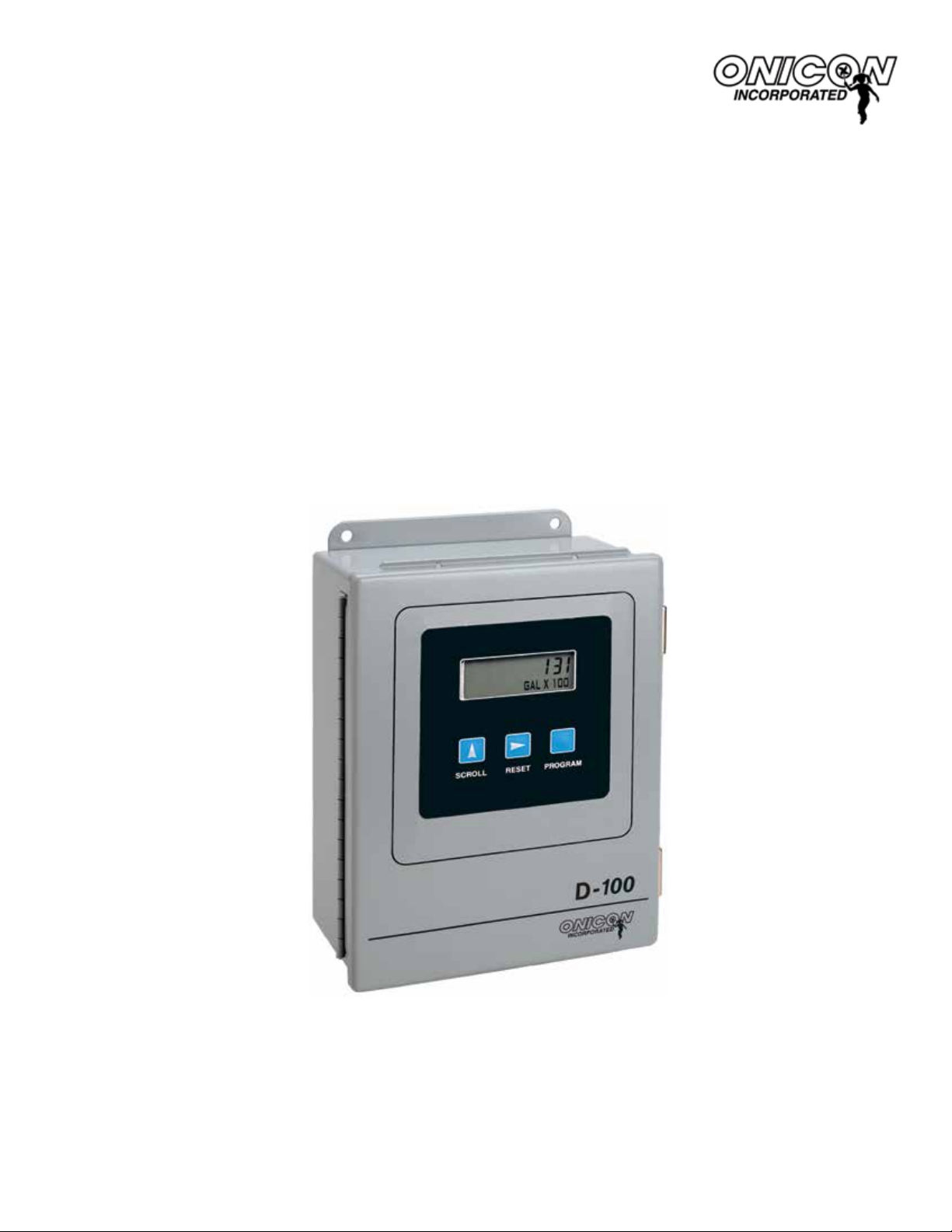
1.2 TYPICAL D-100 NETWORK INTERFACE MODULE
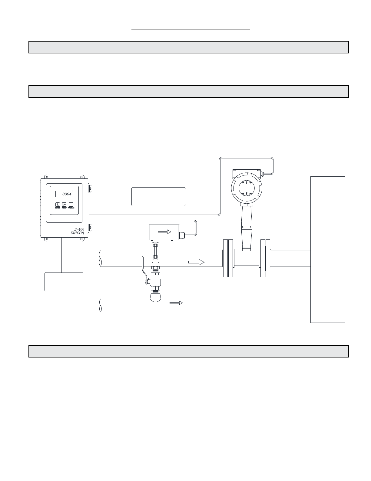
The D-100 is a totalizing display module that provides a local indication of liquid, gas or steam
ow rate and total data. It can also be congured with an optional network interface to
communicate data to the building control network. It is housed in a steel wall mounted
enclosure with a built-in user interface/display.
Flow rate and total data to
Data Acquisition System or
Building Control System
Steam
Building
120VAC or 24VAC
Input Voltage
Domestic Water Supply
1.3 STANDARD FEATURES AND SPECIFICATIONS
• Wall mounted NEMA 13 steel enclosure with 2 line alphanumeric user interface/display
• One congurable pulse/analog rate input with totalizing function
• Internal 24 VDC power supply capable of powering most ow meters
• Scaled pulse (contact closure) outputs for remotely totalizing forward and reverse ow
• Contact closure output to provide an indication of ow direction
11451 Belcher Road South, Largo, FL 33773 • USA • Tel +1 (727) 447-6140 • Fax +1 (727) 442-5699 • sales@onicon.com
D-100 Flow Display Manual 10/14 - 0634-14 / 18340 Page 5
Page 6
GENERAL SPECIFICATIONS
!
ACCURACY
Analog Inputs: 0.1% of full scale
Analog Outputs: 0.1% of full scale
PROGRAMMING
Factory programmed for specic application.
MEMORY
Nonvolatile EEPROM memory retains all program
parameters and totalized values in the event of
power loss.
DISPLAY
Standard: 2-line Alphanumeric LCD displays ow
rate and ow total for the standard ow input
Alpha: 16 character, 0.2” high
Numeric: 7 digit, 0.4” high
Rate Display Range: 0 - 9,999,999
Totalizer Display Range: 0 - ,999,999
The totalizers will roll over to zero when maximum
count is exceeded.
OUTPUT SIGNALS
Pulse Outputs:
Two isolated contact closure outputs for separately
totalizing forward and reverse ow from the
standard ow input. Contact duration: 0.5, 1, 2
or 6 seconds (factory selectable). Default: 0.5
seconds
Maximum contact ratings: 100 mA, 50 VDC
Isolated contact closure output for indicating ow
direction
Maximum contact ratings: 100 mA, 50 VDC
Analog Outputs Options:
Single isolated analog output:
4-20 mA, 0-10 V or 0-5 V
Multiple (4) isolated analog outputs: 4-20 mA,
0-10 V or 0-5 V outputs
Network Interface Options
MODBUS RTU RS485
MODBUS RTU TCP/IP
BACnet MS/TP
BACnet UDP/IP
LONWORKS FTT10A
JCI Metasys - N2
Siemens Apogee - P1 FLN
INPUT SIGNALS
Standard: One totalizing ow input:
4-20 mA, contact closure or pulse
One contact closure input for ow
direction
Optional: Two auxiliary analog rate inputs:
4-20 mA
One digital totalizer input: pulse or
contact closure
Totalizer Range: 0-9,999,999 counts.
Total will rollover to zero when
maximum count is exceeded.
TEMPERATURE RANGE
Ambient temperature range: -20° F to 140° F
Do not install in direct sunlight.
MAINTENANCE
ONICON recommends periodic inspection and
recalibration for sensors connected to the D-100.
No other periodic maintenance is required for the
main unit.
MECHANICAL
Electronics Enclosure:
Standard: Steel NEMA 13, wall mount, 8”x10”x4”
Optional: NEMA 4
ELECTRICAL
WARNING
All electrical connections must be made in
accordance with the imformation provided
here. Failure to do so will result in an
increases risk of injury.
This equipment is intended for INSTALLATION CATEGORY
(OVERVOLTAGE CATEGORY) II applications.
INPUT POWER:
Factory Selectable:
24 VAC: 20 - 28V, 50/60 Hz, 500 mA
120 VAC: 108 - 132V, 50/60 Hz, 250 mA
240 VAC: 207 - 253V, 50 Hz, 250 mA
INTERNAL FUSE RATING:
24 VAC - 1 Amp Slo-Blo, 3AG Fuse
120 VAC - 1/4 Amp Slo-Blo, 3AG Fuse
240 VAC - 1/8 Amp Slo-Blo, 3AG Fuse
OUTPUT:
24 VDC, 250 mA maximum
OVERCURRENT PROTECTIVE DEVICE RATINGS:
Supply mains overcurrent protective devices with the
following ratings:
120 VAC 50/60 Hz – 15 A
240 VAC 50 Hz – 6 A
WIRING:
Flow signals: Use 18-22 ga shielded cable – see ow
meter specication sheet or ow meter manual for
the correct number of conductors.
24 VAC input power: Use PVC jacketed copper cable
with a wire gauge suitable for the length of run and
required maximum current carrying capacity. The
installation must comply with all local, state and
federal building codes.
120/240 VAC input power: Use a three wire service with one
wire a protective earth ground. The installation must
comply with all local, state and federal building codes.
Note: Specications are subject to change without notice.
11451 Belcher Road South, Largo, FL 33773 • USA • Tel +1 (727) 447-6140 • Fax +1 (727) 442-5699 • sales@onicon.com
D-100 Flow Display Manual 10/14 - 0634-14 / 18340 Page 6
Page 7
1.4 ADDITIONAL REQUIRED HARDWARE
i
Flow Meter
ONICON offers a wide variety of ow meters to satisfy most liquid, gas and steam
metering applications. Please refer to ONICON’s ow meter literature, or consult
ONICON or your local representative for help in selecting the ow meter that will best
t your requirements.
1.5 WORKING ENVIRONMENT
The D-100 was designed for installation and use in typical industrial environments that are
free of corrosive liquids and fumes, direct liquid exposure, heavy condensation, temperature
extremes, and vibrations. Do not expose the display to direct sunlight.
The operating ambient air temperature range is - 20° F to 140° F. Electrical power should be
relatively clean, free of high frequency noise, large voltage transients, and protected from power
surges and brown-outs.
1.6 WARRANTY & SERIAL NUMBER
Warranty
ONICON’s 2-year “No-fault” warranty reduces start-up costs by extending coverage for
incidental damage during installation. Certain exclusions apply. Please refer to ONICON’s
Conditions of Sale for details.
Serial Number
The serial number of your D-100 is located outside and inside the enclosure. Also located
inside the enclosure is a label with the serial number of the associated ONICON ow
meter or sensor your D-100 was intended to be used with. The serial numbers are unique
identiers that you should have available when contacting ONICON for assistance
regarding the installation or use of this product.
SECTION: 2.0 UNPACKING
The D-100 is shipped in one package unless optional hardware or equipment is ordered. Notify the
freight carrier and ONICON if any items are damaged in transit.
2.1 CHECKING THAT YOU HAVE RECEIVED EVERYTHING
• Standard Documentation
Enclosed with each D-100 is a comprehensive documentation package that includes the
following items:
The D-100 Installation and Operation Guide
The D-100 Conguration Data Sheet
IMPORTANT NOTE
The ONICON D-100 is delivered fully programmed and ready to use with a specic ow meter.
The serial number of the ow meter and any other sensor used with this D-100 will be found on
a label located inside the enclosure. Do not attempt to use the D-100 with any other ow meter
or sensor. Doing so will result in signicant errors in the ow reading.
11451 Belcher Road South, Largo, FL 33773 • USA • Tel +1 (727) 447-6140 • Fax +1 (727) 442-5699 • sales@onicon.com
D-100 Flow Display Manual 10/14 - 0634-14 / 18340 Page 7
Page 8

Please notify ONICON if any of these items are missing.
• The D-100
Remove the D-100 from the shipping carton and inspect it for physical damage. When
you complete the external inspection, open the enclosure and inspect the interior for signs
of damage in transit. Also, conrm that the circuit boards and connectors are all securely
seated in their sockets. Please notify ONICON immediately if you nd any discrepancies.
• The Flow Meter
The ow meter intended for use with this display came complete with an instruction
manual. Please refer to the ow meter instruction manual for detailed information
regarding the installation, commissioning and operation of the ow meter. Each D-100 is
calibrated to a specic ow meter, the two must be used together as a system. If the ow
meter and display were purchased together, the serial number on the ow meter will be
located on a label inside the D-100.
SECTION 3.0: INSTALLATION
The D-100 should be installed by qualied individuals with knowledge and experience in the heating,
cooling, and uid metering elds. ONICON will be happy to assist with technical recommendations
and to provide guidance by telephone and/or email. On-site eld engineering, installation and service
are also available at an additional cost. The installer should use good trade practices and must adhere
to all state, federal and local building codes.
3.1 SITE SELECTION
Careful attention to the site selection for the system components will help the installers with the
initial installation, reduce start-up problems and make future maintenance easier. For example,
do not install the ow meter where it will be difcult for personnel to perform periodic
maintenance and calibration. When selecting a site for mounting the system components,
consider the criteria under Section 1.5 WORKING ENVIRONMENT, as well as the following:
The D-100
Find an easily accessible location where wire connections can be made and meter readings
can be taken from oor level. Mount the D-100 on a vibration free surface. Avoid locations
such as the plenum of a fan coil, heat exchanger or any housing that may contain electric
motors or other strong sources of electrical interference.
The Flow Meter
Choose the location with the longest straight run of unobstructed pipe. Please refer to the
ow meter installation manual for specic information regarding the straight run
requirements for the ow meter used with this display.
11451 Belcher Road South, Largo, FL 33773 • USA • Tel +1 (727) 447-6140 • Fax +1 (727) 442-5699 • sales@onicon.com
D-100 Flow Display Manual 10/14 - 0634-14 / 18340 Page 8
Page 9
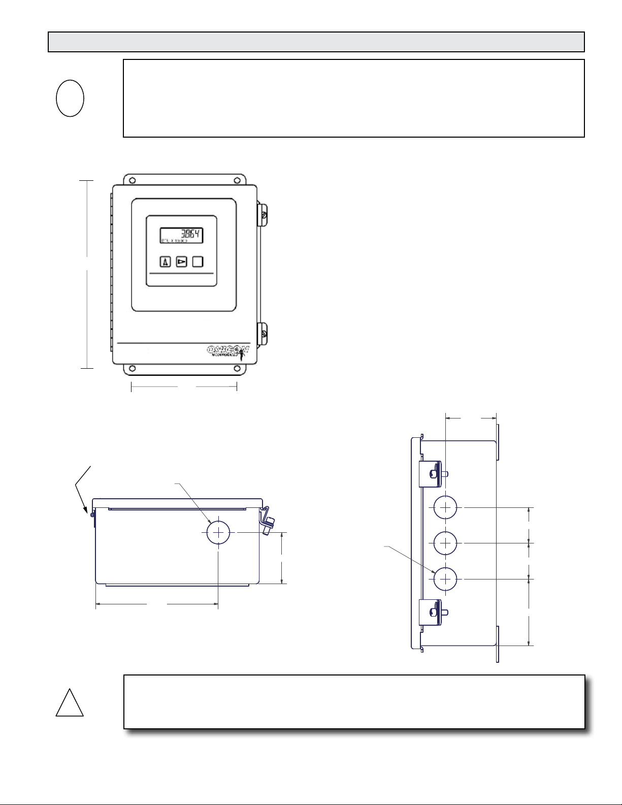
!
3.2 MECHANICAL INSTALLATION
i
The ONICON D-100 Display is a custom calibrated system. Unless specically noted in writing
by ONICON, ALL COMPONENTS (Display and ow meter) share the same serial number and
must be installed together as a system. Mixing components from different systems will result in
signicant errors in calibration.
3.2.1 Main Unit Installation
10 3/4”
SCROLL RESET PROGRAM
6”
D-100
IMPORTANT NOTE
• Find an easily accessible location where electrical
connections can be made and meter readings can be
taken from the oor level.
• Mount the display on a vibration-free surface. Avoid
sites such as the plenum of a fan coil, heat exchanger,
or other housings containing motors. Do not install the
display in direct sunlight.
Use four screws for mounting the display. The
mounting surface must be structurally sound and
capable of withstanding a minimum weight of 40lbs
(18kg). Use the following screws for mounting.
• (4) Machine screws - HHMS .25-20 x 1.5”
• (4) Wood screws - FHLS .25 x 1.5”
• (4) Concrete screws - HHCS .25 x 1.5”
CONDUIT HOL LOCATION
BOTTOM VIEW
HINGE SIDE
SOWN FOR REFERENCE.
01.115
6.000
Do not drill additional holes in this enclosure. Doing so may damage the electronic circuitry
contained within and will void all warranties.
2.500
CONDUIT HOL LOCATION
RIGHT SIDE VIEW
3X 01.115
CAUTION
2.500
1.750
1.750
3.250
11451 Belcher Road South, Largo, FL 33773 • USA • Tel +1 (727) 447-6140 • Fax +1 (727) 442-5699 • sales@onicon.com
D-100 Flow Display Manual 10/14 - 0634-14 / 18340 Page 9
Page 10
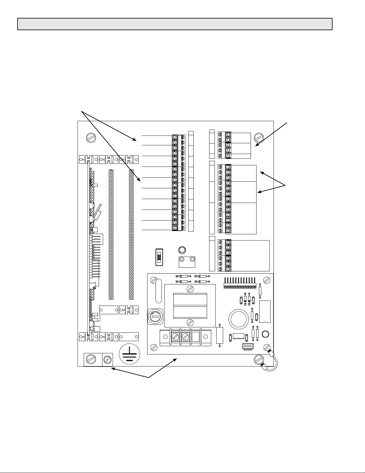
3.3 ELECTRICAL INSTALLATION
The electrical installation of this product must comply with all federal, state and local building
codes. Connect and re-verify all input, output, network interface and safety earth wiring
connections prior to connecting power.
The drawing below shows where signal, power and earth connections are made on the mother
board located inside the D-100 enclosure. Network and digital pulse input connections are
made on the network interface board (not shown). Refer to section 3.3.1 for detailed information
on connecting ow meters, sensors, output signal and power connections.
Pulse and analog output connections
ANALOG INPUTS
OUTPUTS
TOTALIZER OUTPUT
MODE 1
(+)
TOTALIZER OUTPUT
MODE 2
(-)
MODE STATUS
H1
1
H2
1
5
10
15
20
25
30
35
40
45
H3
1
5
10
15
20
25
30
35
40
45
ANNALOG OUTPUT
ANALOG OUTPUT
ANALOG OUTPUT
ANALOG OUTPUT
VAR1
CHANNEL A
CHANNEL B
CHANNEL C
CHANNEL D
ALARM
OUTPUT
S1
RUN
TEST
60 HZ
+
-
+
-
+
-
+
-
D1
D2
T1
LED1
INDICATOR
+ -
15 V PULSE
T1
1
2
3
4
5
6
7
8
9
10
11
12
13
14
15
16
17
18
FLOW
T3
1
2
3
4
5
T4
1
2
3
4
5
6
7
8
9
10
11
12
13
T5
1
2
3
4
5
6
D3
D4
SIGNAL
REFERENCE
SIGNAL
REFERENCE
SHIELDS
FLOW METER INPUTS
24 VDC SUPPLY +
SUPPLY COMMON -
SHIELD
4-20mA +
4-20mA -
FREQUENCY +
FREQUENCY -
DIRECTION +
DIRECTION -
ALARM +
ALARM -
TOP TURBINE
BOTTOM TURBINE
AUXILIARY FLOW METER SIGNALS
4-20mA -
0-10 VDC +
ANALOG COMMON -
ISOLATED ANALOG COMMON -
SCALED +
SCALED -
G
G
+24
+15
J2-12
10
C6
Ai3Ai4
Ai2
Di2
G
60HZ
J2-1
1
5
H3
R7
C5
D5
D6
input connections
Ai2 / Di2
Flow meter
connections
Ai3 & Ai4 analog
C4
R1
U2
R3
LED1
J1
ONICON INC.
20036 Rev. D
1/4 AMP
TB1
F1
C3
L1 N
Not Used
R1
20075-50 REV. A
R5
C1
C2
U1
Input power & earth connections
3.3.1 Input Signal Connections from Flow Meter
Make connections on the mother board, located inside the enclosure, at terminal strip T4.
Analog (4-20mA) signals connect to terminals 4 and 5. Pulse (frequency) signals connect to
terminals 6 and 7. Do not exceed 4.5 in-lb (0.5 Nm) of torque when tightening.
11451 Belcher Road South, Largo, FL 33773 • USA • Tel +1 (727) 447-6140 • Fax +1 (727) 442-5699 • sales@onicon.com
D-100 Flow Display Manual 10/14 - 0634-14 / 18340 Page 10
Page 11
!
3.3.1.1 ONICON Turbine Flow Meters
ONICON turbine ow meters are provided with a number of different output
congurations. These affect the number of wires contained in the cable attached
to the ow meter. Refer to the diagram below and the laminated tag attached to
the ow meter for specic details.
ONICON Turbine Flow Meter
Factory Installed Cable
Flow Meter Inputs
* 24VDC Supply + (Red)
Not UsedL1 N
* Supply Common - (Black)
* Shield
* Frequency + . (Green)
(A) Direction + (Grey)
(A) Direction - (Violet)
(B) Top Turbine (White)
(B) Bottom Turbine (Orange)
Auxiliary Flow Meter Signals
(C or D) 4-20mA + (Blue)
(C or D) 0-10 VDC + (Brown)
(C) Analog Common - (Black)
(D) Isolated Analog Common - (Yellow)
(E) Scaled + (Blue)
(E) Scaled - (Brown)
ONICON turbine flow meters are provided with a variety of output signals. Only the red,
green and black wires are required to power the flow meter and operate the display. For
bi-directional applications, the gray and violet wires are also required to indicate flow
direction.
F-1100, F-1200 & F-1300 Series
Flow Meter Connections
Connections shown with * are
required for all models.
Connections shown with (A)
are required for all
bi-directional models.
Connections shown with (B)
are required for all dual turbine models,
including bi-directional.
For F-1x10, F-1x11 & F-1x30
Connections shown are f or flow meter
output signals not used by the Btu meter.
Both incoming and outgoing connections
are made to the same terminal.
Connections shown with (C)
are used with F-1x10 models, including
bi-directional.
Connections shown with (D)
are used with F-1x11 models, including
bi-directional.
Connections shown with (E)
are used with F-1x30 models, including
bi-directional.
• Top and bottom turbine signals are only used with the F-1200 and FB-1200
ow meters.
• Directional contacts are only used by FB-1200 ow meters.
• Terminal block positions are provided for additional ow meter signals that
may be available, but are not actually used by the D-100.
CAUTION
Shield connections are required for proper operation. Failure to use shielded cable or to properly
terminate shield connections may result in erratic operation. Shields should be terminated in
the D-100 at the terminals provided. The shield connection at the ow meter should be left
unterminated.
11451 Belcher Road South, Largo, FL 33773 • USA • Tel +1 (727) 447-6140 • Fax +1 (727) 442-5699 • sales@onicon.com
D-100 Flow Display Manual 10/14 - 0634-14 / 18340 Page 11
Page 12

3.3.1.2 Input Signal Connections from F-3500 Flow Meter
!
!
Flow Meter Inputs
T4
H1
1
G
G
D3
D4
20075-50 REV. A
G
+15
+24
60HZ
J2-1
J2-12
1
5
10
H3
R7
LED1
J1
R1
1/8 AMP
D1
D2
T1
VAR1
F1
TB1
L1 N Not Used
1
2
3
4
5
6
7
8
9
10
11
12
13
* 24VDC Supply + (Red)
* Supply Common - (Black)
* Shield
* Frequency + (Green)
* Frequency - (Yellow)
Alarm + (Orange)
Alarm - (White)
Auxiliary Flow Meter Signals
T5
1
2
3
4
5
6
4-20mA + (Blue)
0-10 VDC + (Blue)
Isolated Analog Common - (Brown)
Earth (Green/Yellow)*
CAUTION
Factory Installed Cable
F-3500 Flow Meter Connections
Connections shown with * are required.
Connections shown below dashed line
Connections shown below dashed line
are for ow meter output signals not
are for flow meter output signals not used
used by the D-100. Both incoming and
by the BTU meter. Both incoming and
outgoing connections are made to the
outgoing connections are made to the
same terminal.
same terminal.
Connections shown for T5-1 and T5-2
are for the same analog output from the
F-3500. This output can be configured in
the flow meter as a 4-20mA or 0 -10 VDC.
See F-3500 installation and operation guide for additional information on properly grounding the meter.
3.3.1.3 Input Signal Connections from FB-3500 Flow Meter
Flow Meter Inputs
T4
H1
1
G
G
D3
J2-12
D4
20075-50 REV. A
G
+15
+24
60HZ
J2-1
1
5
10
H3
R7
LED1
J1
R1
1/8 AMP
D1
D2
T1
VAR1
F1
TB1
L1 N Not Used
1
2
3
4
5
6
7
8
9
10
11
12
13
* 24VDC Supply + (Red)
* Supply Common - (Black)
* Shield
* Frequency + (Green)
* Frequency - (Yellow)
* Direction + (Orange / Black)
* Direction - (White / Black)
Alarm + (Orange)
Alarm - (White)
Auxiliary Flow Meter Signals
T5
1
2
3
4
5
6
4-20mA + (Blue)
0-10 VDC + (Blue)
Isolated Analog Common - (Brown)
Factory Installed Cable
FB-3500 Flow Meter Connections
Connections shown with * are required.
Connections shown below dashed line are
Connections shown below dashed line
for ow meter output signals not used by
are for flow meter output signals not used
the D-100. Both incoming and outgoing
by the BTU meter. Both incoming and
connections are made to the same
outgoing connections are made to the
terminal.
same terminal.
Connections shown for T5-1 and T5-2
are for the same analog output from the
FB-3500. This output can be configured in
the flow meter as a 4-20mA or 0 -10 VDC.
Earth (Green/Yellow)*
CAUTION
See FB-3500 installation and operation guide for additional information on properly grounding the meter.
11451 Belcher Road South, Largo, FL 33773 • USA • Tel +1 (727) 447-6140 • Fax +1 (727) 442-5699 • sales@onicon.com
D-100 Flow Display Manual 10/14 - 0634-14 / 18340 Page 12
Page 13

!
!
3.3.1.3 ONICON F-3100 and F-3200 Flow Meters
F-3100 & F-3200 Flow
Meter Connections
L1 N Not Used
Flow Meter Inputs
* Shield
* Frequency +
* Frequency -
(A) Direction +
(A) Direction -
Auxiliary Flow Meter Signals
4-20mA +
Analog Common -
(B) Scaled +
(B) Scaled -
* Earth
Outputs Terminal #
* (+) Pulse Output # 1
* (-) Pulse Output # 1
(+) Pulse Output # 2
(-) Pulse Output # 2
(+) 4-20mA Output
(-) 4-20mA Output
(+) Pulse Output # 2
(-) Pulse Output # 2
* Earth
16
17
18
19
9
10
18
19
Connections shown with * are required for
all installations.
Connections shown with (A) are required
for bi-directional flow installations.
Connections shown with (B) are optional
for non bi-directional installations.
Note: The D-100 does not provide power to the F-3100 or F-3200 flow
meter. Input power for the flow meter must be provided separately. See
flow meter manual for detailed wiring instructions.
CAUTION
The D-100 internal 24 V power supply cannot provide power to the F-3100 or F-3200 ow meters.
CAUTION
Shield and earth connections are required for proper operation. Failure to use shielded cable
or to connect earth to both the ow meter and D-100 may result in erratic operation. Shields
should be terminated at the D-100 shield terminals and left unterminated at the ow meter.
11451 Belcher Road South, Largo, FL 33773 • USA • Tel +1 (727) 447-6140 • Fax +1 (727) 442-5699 • sales@onicon.com
D-100 Flow Display Manual 10/14 - 0634-14 / 18340 Page 13
Page 14

!
3.3.1.4 ONICON F-2500 Flow Meters
Flow Meter Inputs
Auxiliary Flow Meter Signals
L1 N Not Used
* Shield
* 4-20mA +
* 4-20mA -
F-2500 Flow Meter
F-2000 Flow Meter
Connections
Connections
Outputs Terminal #
* + 24V
* - ILoop
1
2
(A) Scaled +
(A) Scaled -
* Earth
+ 24V
- Pout
* Earth
Connections shown with * are required for all installations. Connections shown with (A) are optional.
CAUTION
Shield and earth connections are required for proper operation. Failure to use shielded cable
or to connect earth to both the ow meter and D-100 may result in erratic operation. Shields
should be terminated at the D-100 shield terminals and left unterminated at the ow meter.
3
4
11451 Belcher Road South, Largo, FL 33773 • USA • Tel +1 (727) 447-6140 • Fax +1 (727) 442-5699 • sales@onicon.com
D-100 Flow Display Manual 10/14 - 0634-14 / 18340 Page 14
Page 15

• D-100 Display Module •
Input Signal Connections
From F-2600 Flow Meter
!
3.3.1.5 ONICON F-2600 & F-2700 Flow Meters
ANALOG INPUTS
H1
1
ONICON INC.
20036 Rev. D
T3
1
MODE 1
MODE 2
ALARM
OUTPUT
F1
RUN
TEST
60 HZ
T1
+
-
+
-
+
-
+
-
LED1
+ 15 V PULSE
D1
D2
L1 N Not Used
T1
1
2
3
4
5
6
7
8
9
10
11
12
13
14
15
16
17
18
FLOW
INDICATOR
T3
1
2
3
4
5
T4
1
2
3
4
5
6
7
8
9
10
11
12
13
T5
1
2
3
4
5
6
D3
D4
20075-50 REV. A
J2-12
SIGNAL
Ai3Ai4
REFERENCE
SIGNAL
REFERENCE
SHIELDS
FLOW METER INPUTS
24 VDC SUPPLY +
SUPPLY COMMON -
SHIELD
4-20mA +
4-20mA -
FREQUENCY +
FREQUENCY -
DIRECTION +
DIRECTION -
ALARM +
ALARM -
TOP TURBINE
BOTTOM TURBINE
AUXILIARY FLOW METER SIGNALS
4-20mA -
0-10 VDC +
ANALOG COMMON -
ISOLATED ANALOG COMMON -
SCALED +
SCALED -
G
G
G
+24
+15
10
1
5
C5
C6
D5
D6
R1
R5
C1
C2
U1
J1
C3
R1
60HZ
J2-1
H3
R7
C4
R3
OUTPUTS
TOTALIZER OUTPUT
TOTALIZER OUTPUT
MODE STATUS
H2
H3
CHANNEL A
ANNALOG OUTPUT
1
1
CHANNEL B
5
5
ANALOG OUTPUT
CHANNEL C
ANALOG OUTPUT
10
10
CHANNEL D
ANALOG OUTPUT
15
15
20
20
25
25
S1
30
30
35
35
40
40
45
45
VAR1
1/4 AMP
TB1
ANALOG INPUTS
2
3
4
5
T4
1
2
3
4
5
6
7
8
9
U2
10
LED1
11
12
13
Network
Interface
Connection
SIGNAL
REFERENCE
SIGNAL
REFERENCE
SHIELDS
FLOW METER INPUTS
24 VDC SUPPLY +
SUPPLY COMMON -
SHIELD
4-20mA +
4-20mA -
FREQUENCY +
FREQUENCY -
DIRECTION +
DIRECTION -
ALARM +
ALARM -
TOP TURBINE
BOTTOM TURBINE
Ai3Ai4
Ai2
Di2
F-2600 / F-2700 Flow
F-2600 Flow Meter
Connections
Meter Connections
OUT
FREQ
OUT
OPTIONAL
BACKLIT
POWER
LOOP
POWER
PULSE
BACK VIEW
CAUTION
Shield and earth connections are required for proper operation. Failure to use shielded cable
or to connect earth to both the ow meter and D-100 may result in erratic operation. Shields
should be terminated at the D-100 shield terminals and left unterminated at the ow meter.
11451 Belcher Road South, Largo, FL 33773 • USA • Tel +1 (727) 447-6140 • Fax +1 (727) 442-5699 • sales@onicon.com
D-100 Flow Display Manual 10/14 - 0634-14 / 18340 Page 15
Page 16

!
3.3.1.6 ONICON F-4200 Flow Meters
!
!
Turn off mains power at the source prior to making power connections to the F-4000. Contact
with exposed live wiring may result in electric shock, burns and/or serious injury.
Flow Meter Connections
D-100 F-4200
TEMPERATURE INPUTS
T3
MODE 1
MODE 2
MODE STATUS
SUPPLY TEMP
ANALOG OUTPUT
RETURN TEMP
ANALOG OUTPUT
BTU RATE
ANALOG OUTPUT
DELTA T
ANALOG OUTPUT
FLOW RATE
ANALOG OUTPUT
ALARM
OUTPUT
S1
VAR1
F1
1/8 AMP
TB1
RUN
TEST
60 HZ
T1
LED1
+ -
15 V PULSE
D1
D2
L1 N Not Used
T1
10
11
12
13
14
15
16
17
18
FLOW
INDICATOR
1
2
3
4
5
6
7
8
9
1
2
3
4
5
FLOW METER INPUTS
T4
1
2
3
4
5
6
7
8
9
10
11
12
13
AUXILIARY FLOW METER SIGNALS
T5
1
2
3
4
5
6
D3
+15
+24
J2-12
D4
10 5 1
C3
R1
20075-50 REV. A
SIGNAL
REFERENCE
SIGNAL
REFERENCE
RETURN SUPPLY
SHIELDS
24 VDC SUPPLY +
SUPPLY COMMON -
SHIELD
4-20mA +
4-20mA -
FREQUENCY +
FREQUENCY -
DIRECTION +
DIRECTION ALARM +
ALARM -
TOP TURBINE
BOTTOM TURBINE
4-20mA +
0-10 VDC +
ANALOG COMMON ISOLATED ANALOG COMMON SCALED +
SCALED -
G
G
G
60HZ
J2-1
H3
R7
C6
C5
D5
D6
C4
R1
R5 R3
C1
C2
U1
J1
U2
LED1
H1
1
ONICON, INC.
20036 Rev. D
BTU METER OUTPUTS
BTU CONTACT OUTPUT
BTU CONTACT OUTPUT
H2
1
5
10
15
20
25
30
35
40
45
WARNING
J11
J10
UP
DOWN
IMPORTANT NOTE
DC powered version of the F-4200
F1
DC
TB1
I OUT 1
TB-1
NEU
AC
GND
HOT
DC
NEG - GND
POS +
TB-2
TB-3
TB-4
RELAY 1
TB-5
TB-6
TB-7
DIGITAL IN1
TB-8
TB-9
TB-10
DIGITAL IN2
TB-11
TB-12
TB-13
TB-14
PGEN
TB-15
TB-16
DC
J9
NEG -
POS +
11.5 - 28.5 VDC
GND
Protective
Earth
S1
T4
1
2
3
4
5
6
7
8
9
10
11
12
13
+24 (RED)
-Common (BLACK)
* Shield
* 4-20 mA +
* 4-20 mA -
Direction +
Direction -
I OUT 1
RELAY 1 DIGITAL IN1 DIGITAL IN2
TB-1
TB-2
TB-3
TB-4
TB-5
TB-6
TB-7
TB-8
TB-9
TB-10
TB-11
TB1
DC
DC
NEG -
POS +
11.5 - 28.5 VDC
GND
TB-12
TB-13
TB-14
PGEN
TB-15
TB-16
CAUTION
Shield and earth connections are required for proper operation. Failure to use shielded cable
or to connect earth to both the ow meter and D-100 may result in erratic operation. Shields
should be terminated at the D-100 shield terminals and left unterminated at the ow meter.
11451 Belcher Road South, Largo, FL 33773 • USA • Tel +1 (727) 447-6140 • Fax +1 (727) 442-5699 • sales@onicon.com
D-100 Flow Display Manual 10/14 - 0634-14 / 18340 Page 16
Page 17

!
3.3.1.7 ONICON F-5100 Series Flow Meters
F-5100 Flow Meter
Connections
L1 N Not Used
* Earth
Flow Meter Inputs
* 24 VDC Supply +
* Supply Common -
* Shield
* 4-20mA +
Inputs & Outputs
* + 24V
* - Common B6
* 4-20mA
* Earth
Terminal #
B5
C5
Connections shown with * are required for
all installations.
CAUTION
Shield and earth connections are required for proper operation. Failure to use shielded cable
or to connect earth to both the ow meter and D-100 may result in erratic operation. Shields
should be terminated at the D-100 shield terminals and left unterminated at the ow meter.
11451 Belcher Road South, Largo, FL 33773 • USA • Tel +1 (727) 447-6140 • Fax +1 (727) 442-5699 • sales@onicon.com
D-100 Flow Display Manual 10/14 - 0634-14 / 18340 Page 17
Page 18

!
3.3.1.8 ONICON F-5200 Series Flow Meters
F-5200 Flow Meter
Factory Installed Cable
D-100
L1 N Not Used
Flow Meter Inputs
* 24 VDC Supply +
* Supply Common - (Black)
* Shield
* 4-20mA + (Blue)
* 4-20mA - (Brown)
Scaled + (White)
Scaled - (Orange)
(Red)
Connections shown with * are
required for all models
Connections shown are for
flow meter output signals not
used by the display.
Both incoming and outgoing
connections are made to the
same terminal.
CAUTION
Shield connections are required for proper operation. Failure to use shielded cable or to
properly terminate shield connections may result in erratic operation. Shields should be
terminiated in the D-100 at the terminals provided. The shield connection at the ow meter
should be left unterminated.
11451 Belcher Road South, Largo, FL 33773 • USA • Tel +1 (727) 447-6140 • Fax +1 (727) 442-5699 • sales@onicon.com
D-100 Flow Display Manual 10/14 - 0634-14 / 18340 Page 18
Page 19

3.3.2 Frequency / Pulse Flow Input (Di2)
The D-100 is provided with a separate input for frequency or scaled pulse ow signals,
(T4, terminals 6 and 7). This input can be congured to accept an active, positive going
pulse (5-24 VDC) output signal, an open collector output signal or a contact closure (dry
contact) output. The maximum input frequency is 500 Hz. Contact ONICON for technical
assistance in conguring and programming this input. When this ow input is used the
display menu pages will indicate Di2 on the rate and total(s) pages.
3.3.3 Analog Flow Input (Ai2)
The D-100 is provided with a separate input for analog
ow signals (T4 terminals 4 and 5). This input can be
congured to accept active or passive (loop powered)
4-20 mA signals. Contact ONICON for technical
assistance in conguring and programming this input.
When this ow input is used the display menu pages will
indicate Ai2 on the rate and total(s) pages.
3.3.4 Directional Contacts
The D-100 is provided with a separate input for
determining ow direction. Connections for this input
are made at T4 terminals 8 (+) and 9 (-). This input can be
connected to a non- polarized contact closure relay or an
open connector output. Note that the input is polarized
for sinking (NPN) open collector outputs. Totals will
accumulate in the (+) Mode 1 registers whenever the
contacts are closed.
3.3.5 Ai3 and Ai4 Analog Inputs
The D-100 can be provided with two optional analog
inputs capable of powering any standard 4-20mA loop
powered sensor. The inputs can also be congured
from the factory to accept an active (powered) 4-20mA
signal. Rate data from the two sensors is available via the
network interface and the analog 4-20mA signals can be
replicated via the optional multi-analog output board.
Analog input Ai3 is connected to T3 terminals 1 (+) and
2 (-). Analog input Ai4 is connected to T3 terminals 3 (+)
and 4 (-). Do not exceed 4.5 in-lb (0.5 Nm) of torque,
when tightening the terminals.
ANALOG INPUTS
T3
1
2
3
4
5
T4
1
2
3
4
5
6
7
8
9
10
11
12
13
T5
1
2
3
4
5
6
SIGNAL
REFERENCE
SIGNAL
REFERENCE
SHIELDS
FLOW METER INPUTS
24 VCD SUPPLY +
SUPPLY COMMON -
SHIELD
4-20 mA +
4-20 mA -
FREQUENCY +
FREQUENCY -
DIRECTION +
DIRECTION -
ALARM +
ALARM -
TOP TURBINE
BOTTOM TURBINE
AUXILIARY FLOW METER SIGNALS
4-20 mA +
0-10 VDC +
ANALOG COMMON -
ISOLATED ANALOG COMMON -
SCALED +
SCALED -
Ai3
Ai4
Ai2
Di2
3.3.6 Digital Pulse Input (Di3)
The D-100 can be provided with an optional digital pulse input. This option is only
available on displays provided with serial communications. It allows the D-100 to receive
a pulse input from an external device such as a power meter or gas meter. The pulses are
totalized in an internal register and are available via the serial communications network.
This register can be zeroed on demand via the front panel or over the network. When this
pulse input is used the display menu page will indicate Di3 on the total page. Contact
ONICON for more information.
11451 Belcher Road South, Largo, FL 33773 • USA • Tel +1 (727) 447-6140 • Fax +1 (727) 442-5699 • sales@onicon.com
D-100 Flow Display Manual 10/14 - 0634-14 / 18340 Page 19
Page 20

3.3.7 Totalizer Outputs and Mode Status
For unidirectional ow applications, the output relay for
ow total is located on the mother board at T1, terminals 1
and (+) 2 mode 1. The value of each “closure” is listed on
the conguration data sheet and is the same as the ow total
multiplier displayed on the LCD (example: each closure = 100
Gallons). This information is also included on a label inside
the D-100. For bi-directional ow applications, connections
for the (+) mode 1 ow total output relay are at T1 terminals 1
and 2. The (-) mode 2 ow total output relay connections are at
T1 terminals 3 and 4. Flow direction is indicated by the mode
status output (T1 pins 5 and 6). The table below describes the
relationship between (+) mode 1 and (-) mode 2 totals and
forward and reverse ow for ONICON insertion turbine and
inline electromagnetic ow meters. Do not exceed 4.5 in-lb (0.5
Nm) of torque, when tightening the terminals.
OUTPUTS
TOTALIZER OUTPUT
TOTALIZER OUTPUT
MODE 1
(+)
MODE 2
(-)
MODE STATUS
CHANNEL A
ANALOG OUTPUT
CHANNEL B
ANALOG OUTPUT
CHANNEL C
ANALOG OUTPUT
CHANNEL D
ANALOG OUTPUT
ALARM
OUTPUT
T1
1
2
3
4
5
+
_
+
_
+
_
+
_
6
7
8
9
10
11
12
13
14
15
16
17
18
Flow Meter
Model
FB-1200 Series
FB-1200 Series
F-3000 Series Flow toward (+) sign
F-3000 Series Flow toward (-) sign
F-4000 Series Flow forward (-) sign
F-4000 Series Flow forward (-) sign
Flow Direction
Relative to Direction
Arrow on Meter
Flow in the direction
of arrow
Flow reverse from
direction arrow
Flow Meter
Output Condition
D-100 Mode
Status Indicator
(T1 - Pins 5 & 6)
D-100 Register
Accumulating
Totals
Closed contact Open contact + Mode 1
Open contact Closed contact - Mode 2
Not energized
(open)
Energized
(closed)
Energized
(closed)
Not Energized
(open)
Closed contact - Mode 2
Open contact + Mode 1
Open contact + Mode 1
Closed contact - Mode 2
3.3.8 Isolated Analog Outputs
The D-100 can be congured to provide up to four isolated analog outputs. These
outputs can be used to replicate the incoming analog signals. The output signal type
can be 4-20 mA, 0-10 VDC or 0-5 VDC and is eld congurable. Contact ONICON for
assistance in reconguring or reprogramming the analog inputs. See the conguration
data sheet provided or the label located inside the D-100 for output specic conguration
information. Analog output signal connections are made at T1 terminals 7 through 14.
Do not exceed 4.5 in-lb (0.5 Nm) of torque, when tightening the terminals.
11451 Belcher Road South, Largo, FL 33773 • USA • Tel +1 (727) 447-6140 • Fax +1 (727) 442-5699 • sales@onicon.com
D-100 Flow Display Manual 10/14 - 0634-14 / 18340 Page 20
Page 21

3.3.9 Input Power
!
!
The D-100 can be ordered from the factory with input voltages of 24VAC 50/60Hz,
120 VAC 50/60 Hz or 240 VAC 50 Hz. Please note that these are not eld selectable
options. Conrm that the correct input voltage conguration has been provided prior to
making any connections.
WARNING
Conduit openings in the D-100 enclosure must be closed with UL listed ttings applicable to
NEMA 13 enclosures, and mains voltage connections must be made through the pre-drilled
conduit/strain relief opening located at the bottom of the enclosure. Failure to do so will result
in an increased risk of injury.
WARNING / CAUTION
The protective earth connection must be made as shown. Failure to do so will result in an
increased risk of injury and erratic operation.
Connect the power source to the D-100 through the conduit opening located on the
bottom of the enclosure. Attach the wires to the appropriate screw terminals as shown.
Connect the protective earth wire to the earth lug shown. Do not exceed 13 in-lb (1.5 Nm)
of torque when tightening.
As power is initially applied to the D-100, immediately conrm that the “power” light
is illuminated and the display is scrolling throught the character diagnostic test. The
test will begin by indicating the letter P in every position followed by a countdown from
9 to 0 for each digit. If this does not occur, disconnect power immediately and re-verify all
wiring connections. Contact ONICON if the problem persists.
Operating from 120 or 240 VAC mains power
Utilize an electrically clean power line, free of electrical noise and protected from high
voltage spikes, power surges, and brownouts. The power source should be a separate line
with its own circuit protection device. Refer to Section 1.3 of this manual for the
appropriate overcurrent device ratings. Use a 3-wire service in which one wire is a
protective earth ground.
H1
1
F1
Earth Connection
1/4 AMP
1/4
G
G
D3
J2-12
D4
20075-50 REV. A
G
+24
+15
60HZ
J2-1
10
1
5
H3
R7
LED1
J1
R1
D1
D2
T1
VAR1
F1
TB1
L1 N Not Used
AMP
TB1
L1 N Not Used
Input Power Connection
27 OHM 5%
3W
11451 Belcher Road South, Largo, FL 33773 • USA • Tel +1 (727) 447-6140 • Fax +1 (727) 442-5699 • sales@onicon.com
D-100 Flow Display Manual 10/14 - 0634-14 / 18340 Page 21
Page 22

Operating from 24 VAC power
The D-100 can be factory congured to operate from 24 ±4 V 50/60 Hz power. Be sure to
connect a separate protective earth wire to the protective earth lug provided and shown
below.
Do not exceed 13 in-lb (1.5 Nm) of torque when tightening.
H1
1
Earth Connection
1/4 AMP
F1
G
G
D3
J2-12
D4
20075-50 REV. A
G
+24
+15
60HZ
J2-1
10
1
5
H3
R7
LED1
J1
R1
D1
D2
T1
VAR1
F1
TB1
L1 N Not Used
AMP
TB1
L1 N Not Used
OHM 5%
3W
Input Power Connection
11451 Belcher Road South, Largo, FL 33773 • USA • Tel +1 (727) 447-6140 • Fax +1 (727) 442-5699 • sales@onicon.com
D-100 Flow Display Manual 10/14 - 0634-14 / 18340 Page 22
Page 23

SECTION 4.0: D-100 START-UP AND COMMISSIONING
4.1 DISPLAY AND KEYPAD
The display contains two lines of alphanumeric characters. The rst line displays the numerical
value of the quantity described by the second line of the display. The second line contains the
engineering units and a multiplier, which can range from 1 to 1,000,000. The multiplier is the
value which the number on the top line must be multiplied by to achieve the correct value.
Three membrane keys are provided to operate the display
and program the meter.
When operating in the RUN mode, the SCROLL button
advances the display from one page to the next. A total of
up to eight different pages may be available for display
depending on whether the ow meter is unidirectional or
bi-directional.
The RESET button, if enabled, allows totals to be reset to zero.
The PROGRAM button is not active when operating in the
RUN mode.
4.2 PROCESSOR START-UP
GAL X 100
When power is applied to the display, alphanumeric characters appear on the two lines of the
display indicating the display is operating. Press and release the SCROLL button on the front
panel. Observe the display cycle to the next page.
Successively pressing the SCROLL button will cycle the display through the run mode pages
summarized in the tables below.
Select the FLOW RATE page. Note the displayed ow rate. Conrm that the ow rate value is in
the correct range.
Unidirectional Flow
Page No. Display Name Selectable Units
1 Flow Total Ai2/Di2 Gal, Liter, M
2 Flow Rate Ai2/Di2 GPM, GPH, MGD, l/s, l/min, l/hr, M
3
, lb mass, kg mass, Ft3, SCF, NCM
3
/hr, Ft3/m, lb/hr, kg/hr,
SCFH, SCFM, NCMH
3 Analog Input Ai3 DEG F, DEG C, PSI, BAR, KPASCL, GPM, L/S, M3/H, CFS, CFM,
KBTU/H, KW, TON, %RH, SCFM, SCFH, NCMH, None
4 Analog Input Ai4 DEG F, DEG C, PSI, BAR, KPASCL, GPM, L/S, M3/H, CFS, CFM,
KBTU/H, KW, TON, %RH, SCFM, SCFH, NCMH, None
5 Digital Input Di3 PULSE COUNT ONLY (Engineering units entered as text)
6 Alarm Status None
7 Serial Number None
11451 Belcher Road South, Largo, FL 33773 • USA • Tel +1 (727) 447-6140 • Fax +1 (727) 442-5699 • sales@onicon.com
D-100 Flow Display Manual 10/14 - 0634-14 / 18340 Page 23
Page 24

Bi-directional Flow
Page No. Display Name Selectable Units
1 (+) Mode 1 Total Gal, Liter, M
2 (-) Mode 2 Total Gal, Liter, M
3 Flow Rate Ai2/Di2
GPM, GPH, MGD, l/s, l/min, l/hr, M
SCFH, SCFM, NCMH
3
, Ft3, lb mass, kg mass, SCF, NCM
3
, Ft3, lb mass, kg mass, SCF, NCM
3
/hr, Ft3/m, lb/hr, kg/hr,
4 Analog Input Ai3 DEG F, DEG C, PSI, BAR, KPASCL, GPM, L/S, M3/H, CFS, CFM,
KBTU/H, KW, TON, %RH, SCFM, SCFH, NCMH, None
5 Analog Input Ai4 DEG F, DEG C, PSI, BAR, KPASCL, GPM, L/S, M3/H, CFS, CFM,
KBTU/H, KW, TON, %RH, SCFM, SCFH, NCMH, None
6 Digital Input Di3 PULSE COUNT ONLY (Engineering units entered as text)
7 Alarm Status None
8 Serial Number None
4.3 UNITS AND MULTIPLIERS
The operating mode, engineering units and multipliers are programmed into the D-100 at the
factory. These settings may be re-programmed in the eld. Please contact ONICON for assistance
if changes are required.
4.4 ANALOG OUTPUTS
The D-100 is capable of providing up to four analog outputs (optional). Changing any of the
displayed units or multipliers will affect the analog outputs. If any unit or multiplier values are
changed at the D-100, the analog output value(s) will also be changed. If you are unsure of the
ramications of any changes you are contemplating, please contact ONICON for assistance.
4.5 ENABLING / DISABLING FRONT PANEL RESET
The table below explains how to enable or disable the FRONT PANEL RESET.
STEP ACTION REACTION COMMENT
1 With the display running, open the
front panel and locate DEV ADD/
PROG ENAB. Press DEV ADD/
PROG ENAB and then release it.
2 Close the front panel.
3 Press the PROGRAM button. (If
you do not press the PROGRAM
button, the meter will revert to the
run mode after ve minutes.)
4 Press the PROGRAM button. The FRONT PANEL RESET page
5 Press the SCROLL button. The setting will toggle
6 Press the PROGRAM button. The SAVE CHANGES page appears
7 Press the SCROLL button. The N changes to Y. The Y must be selected for the
8 Press the PROGRAM button. The new setting is saved and the
None DEV ADD/PROG ENAB is
located in the lower left
corner of the processor board.
(see appendix page A-2.)
The display changes to program
mode and the DEVICE ID page will
appear with the rst digit of the
address ashing.
appears with the N or Y ashing.
between N and Y.
with the N ashing.
display reverts to the run mode.
The PROGRAM button is on
the front panel.
Enable or disable the FRONT
PANEL RESET as necessary.
The new FRONT PANEL
RESET setting must be saved
to take effect.
change to take effect.
11451 Belcher Road South, Largo, FL 33773 • USA • Tel +1 (727) 447-6140 • Fax +1 (727) 442-5699 • sales@onicon.com
D-100 Flow Display Manual 10/14 - 0634-14 / 18340 Page 24
Page 25

4.6 COMMISSIONING
pp
p
;
g
y
d
gy (
Upon initial installation, it is strongly recommended that both the D-100 and its associated ow
meter be commissioned to ensure that they are properly installed and functioning correctly.
This process involves verifying the mechanical installation, measuring ow signals and then
comparing these measurements to the specied installation and operating parameters listed on
the certicate of calibration provided with the display. The data collected during this initial
commissioning process will then serve as baseline data for periodic revalidation of the meter
operation.
INTEGRATED D-100 DISPLAY
COMMISSIONING PROCEDURE
Please read all installation instructions carefully before
proceeding. Wiring diagrams are located in this manual.
Use the display Certicate of Calibration to verify that
the specied installation & operating parameters match
the actual conditions at the location where the display
is installed. A worksheet for checking these steps and
recording measured values is located on the following
page.
METER INFORMATION
Meter Tag:
BTU Meter Model: SYSTEM-30
Serial No: 134036
SPECIFIED INSTALLATION & OPERATING PARAMETERS
Pipe Information: 1 Inch Copper Tube
Design Maximum Flow Rate: 40.0 GPM
Design Supply Temperature: MODE 1: 45°F
Design Return Temperature: MODE 1: 55°F
Fluid: 25% Ethylene Glycol
Fluid Specific Heat: 0.885 BTU/lb°F
Fluid Density: 65.06 lb/ft³
CONFIGURATION DATA
Enclosure Type:
Input Supply Voltage: 24 AC/DC
Thermowell Type:
Calibrated By: Date: 09/01/2004
ONICON Incorporated certifies that the flow and temperature sensors provided with this Btu meter have been individually calibrated based on the
a
CERTIFICATE OF CALIBRATION
Shane Hamilton
rovided above
standards directl
lication specific data
1500 North Belcher Road, Clearwater, Florida 33765 Tel (727) 447-6140 Fax (727) 442-5699
usin
traceable to the U.S. National Institute of Standards an
CALIBRATION AND PROGRAMMING DATA
Firmware Version: CFM4.6S30
Communications Protocol:
Device Network Address:
Flow Sensor MF Code: 547.500
Programmed Units & Multipliers:
Energy Total: BTU x 1K Energy Rate: BTU/HR x 1K
Flow Total: GAL x 10 Flow Rate: GPM x 1
Temperature: °F
Damping: 5
Pulse Duration: 500 ms
Supply Temperature Slope: 9.969 Offset: -0.870
Return Temperature Slope: 10.004 Offset: -0.130
OUTPUT SIGNAL SCALING
Energy Total(s): 1 Pulse = BTU x 1K
Flow Rate: NA
Energy Rate: NA
Supply T: NA
Return T: NA
Delta T: NA
Technolo
N.I.S.T.).
1. Conrm that the D-100 is being
installed with the correct ow meter
and any optional sensors.
2. Conrm that the D-100 is being
installed in accordance with
Sections 1.5 and 3.1 of this manual.
Check the label inside the front cover of the D-100 and conrm that the
serial numbers match the serial numbers of the ow meter and any optional
sensors being used.
Conrm that the installation location is not in direct sunlight and is
removed from sources of strong electrical interference. The display should
be mounted on a vibration-free surface where it will be protected against
spraying, splashing and the seepage of water.
3. Conrm the pipe diameter and pipe
material.
Conrm that the ow meter is tagged for the pipe diameter and material in
which it is to be installed and that this information matches the information
provided on the display certicate of calibration. When in doubt, measure
the circumference of the pipe.
Pipe O.D. = (circumference / 3.14) – (insulation thickness x 2)
4. Conrm that the ow meter installation
conforms to the requirements specied
in the ow meter installation manual.
Verify that the ow meter is installed in a location with enough straight
unobstructed run upstream and downstream of the pipe. Also verify that
the ow meter is properly oriented with respect to ow direction, and for
insertion meters ensure that the meter is installed to the correct insertion
depth.
5. Conrm that any optional sensors are
properly installed.
Verify that any optional sensors connected to the D-100 are installed in
accordance with the manufacturer’s installation instructions. Also conrm
that the sensor output matches the information shown on the D-100 C of C.
6. Conrm that the correct supply voltage
has been provided.
Verify and measure the AC input voltage to the display.
Input voltages should be within the following ranges.
24VAC: 20 – 28VAC
24VAC when connected to an F-3500 and the D-100 is equipped with a
multi-analog board: 21.6 – 28VAC
120VAC: 108 - 132 VAC
230VAC: 207 - 253 VAC
In order to proceed with the following steps, the display, ow meter and optional sensors must be operating and there must
be ow in the pipes. Flow signal readings should be taken while holding the ow rate constant, if possible.
7. Select the ow rate page on the D-100
front panel display.
Scroll through the D-100 display pages and select the ow rate page. Verify
that the engineering units and multiplier shown match those on the C of C.
8. Note and record the ow reading. Note the displayed ow rate and conrm that it is within the expected
range. For D-100 displays connected to ow meters with integral displays,
conrm that the ow readings shown on the two displays agree. Record the
ow rates.
11451 Belcher Road South, Largo, FL 33773 • USA • Tel +1 (727) 447-6140 • Fax +1 (727) 442-5699 • sales@onicon.com
D-100 Flow Display Manual 10/14 - 0634-14 / 18340 Page 25
Page 26

9. For ow meters that provide a
frequency output, measure and
record output(s). Compare calculated
vs. displayed ow rates.
(F-1200 or FB-1200 only).Conrm both
turbines produce pulses
10. Compare and record the displayed values with those shown on the building
control system.
End of standard commissioning. Please contact ONICON if any questions arise.
The average frequency output signal is a 0-15 VDC pulsed output
ranging up to 200 Hz and must be measured with a frequency counter or
oscilloscope. Measure DC Frequency (Hz) at T4 from terminal 6(+) to 7(-).
GPM = Frequency in Hz X 60 X Meter Factor in ppg (refer to calibration tag
for meter factor)
For the F-1200 or FB-1200 Dual Turbine model, also measure and record
the top and bottom turbine signals.
Top Turbine: T4-12(+) to T4-2(-) Bottom Turbine: T4-13(+) to T4-2(-)
Also measure DC volts on same terminals. 5 to 7 VDC is normal for a
spinning turbine, 0 or 14+ VDC indicates a stopped turbine. (1 to 4 VDC
could indicate a problem.)
Scroll through the D-100 menu pages and conrm that the rate and total
current values and engineering units shown agree with the information
shown on the building control system display. Record the results.
COMMISSIONING WORKSHEET
Please read all installation instructions carefully prior to proceeding with these steps. Wiring
diagrams are located in this manual. Use the following worksheet for checking off the
commissioning steps and recording measured values.
Step Test/Measurement D-100 S/N: D-100 S/N: D-100 S/N:
1. Conrm and record
serial number(s)
Flow meter:
Sensor(s):
Flow meter:
Sensor(s):
Flow meter:
Sensor(s):
2. Proper installation site
selection (Y / N)
3. Record pipe diameter
4. Record number of
unobstructed upstream/
downstream pipe
diameters
5. Sensor(s)properly
installed (Y / N)
6. Record supply voltages
7. Verify that engineering
units & multipliers match
(Y/N)
8. Record ow rate and
total(s)
9. Record actual and
calculated values
10. Record displayed values D-100:
Flow rate:
Mode 1 total:
Mode 2 total:
Actual:
Calculated:
Flow rate:
Mode 1 total:
Mode 2 total:
Actual:
Calculated:
D-100:
Flow rate:
Mode 1 total:
Mode 2 total:
Actual:
Calculated:
D-100:
System:
System:
System:
11451 Belcher Road South, Largo, FL 33773 • USA • Tel +1 (727) 447-6140 • Fax +1 (727) 442-5699 • sales@onicon.com
D-100 Flow Display Manual 10/14 - 0634-14 / 18340 Page 26
Page 27

SECTION 5.0: DIAGNOSTICS
i
i
5.1 DIAGNOSTICS
The ONICON D-100 display is programmable. Factory programmed settings provide rate and
total values in accordance with the customer’s application data. Refer to the D-100 calibration
sheet for a complete listing of factory settings. These settings may be reviewed and changed with
assistance from ONICON factory service personnel. The display is also equipped with diagnostic
indicator lights and self diagnostic test signals that conrm the operation of the microprocessor
and its input circuitry. Please contact the ONICON factory service personnel if any of the
diagnostic lights or test signals listed below indicates a potential problem with the operation of
the Btu meter.
5.1.1 Diagnostic Lights
Low Voltage Power Supply
Located on the power supply board inside the System-10 BTU Meter (refer to page A-3),
these two LEDs will be illuminated when the positive and negative ve volt supplies
are present.
Liquid Flow
Located just above the power supply on the motherboard (refer to page A-1) is the ow
indicator LED. The LED will ash at a rate that is proportional to the liquid ow rate.
An unlit LED indicates no ow signal.
5.1.2 Flow Test Signals
Located on the right side of the motherboard (refer to A-1) immediately above the power
supply board is a three position slide switch used to test the ow input. When the switch
is in the top position, the input is connected to the ow meter. When the switch is in the
middle position, the input is connected to two test terminals used to apply a variable
frequency to simulate ow. When the switch is in the bottom position, the input is
connected to a 50/60 Hz signal that simulates a xed ow rate. Refer to the calibration
certicate to determine the correct display reading when operating in the 50/60 Hz test
mode.
IMPORTANT NOTE
The second line of the display will alternate between TEST MODE and the normal display of
engineering units and multipliers whenever the ow test switch is in the TEST or 60 Hz positions.
IMPORTANT NOTE
After operating for ve minutes in either the TEST or 60 Hz mode, the displayed ow and energy
rate will be disabled, and the meter will report a zero ow rate and a zero energy rate to the
network. The meter will remain in this state until the switch is set to RUN.
5.1.3 Ai3 & Ai4 Test Signals
As you are facing the component side of the processor board, the Ai3/Ai4 Test push button
is along the top edge of the board just to the left of the at ribbon cable. It is labeled TEMP
TEST. When pressed, a xed current will be applied to each sensor input. Both Ai3 and
Ai4 will produce an output equal to 37.5% of their programmed full scale output. This test
conrms the operation of the D-100 processor board input circuitry for Ai3 and Ai4.
11451 Belcher Road South, Largo, FL 33773 • USA • Tel +1 (727) 447-6140 • Fax +1 (727) 442-5699 • sales@onicon.com
D-100 Flow Display Manual 10/14 - 0634-14 / 18340 Page 27
Page 28

5.2 TROUBLESHOOTING GUIDE FOR D-100 DISPLAY
NOTE: Also refer to the COMMISSIONING GUIDE located on the preceding pages.
Reported Problem Possible Solutions
Flow rate is indication zero ow.
(When uid is owing in the pipe.)
• Verify that the correct supply voltage is
present at the ow meter power input.
• Verify that the ow meter signal outputs
are properly wired to the display.
• For insertion meters, verify that the
meter is correctly inserted and parallel
with the pipe.
• For turbine meters, verify that the turbines
are not clogged with debris.
• Re-conrm that there is really ow in the
pipe.
Displayed ow rate is too high or too low. • Verify that the serial number of the ow
meter matches the serial number shown
on the label inside the D-100 front cover.
• Verify that the correct supply voltage is
present at the ow meter power input.
• Verify that the pipe diameter matches the
diameter shown on the calibration
certicate and on the ow meter tag.
• For insertion meters, verify that the
meter is correctly inserted and parallel
with the pipe.
• For turbine meters, verify that the turbines
are not clogged with debris.
Ai3 and/or Ai4 sensor values are too high or
too low.
• Verify that the sensor scaling matches
that programmed values shown on the
label inside the D-100 front cover and on
the calibration certicate.
• Conrm that the control system is
correctly scaled.
Data is not available at the control system. • Verify network addresses are properly
programmed into the D-100.
• If applicable, verify the Baud rate.
• Check the polarity of the network
connections.
For technical assistance, contact ONICON Incorporated at (727) 447-6140.
11451 Belcher Road South, Largo, FL 33773 • USA • Tel +1 (727) 447-6140 • Fax +1 (727) 442-5699 • sales@onicon.com
D-100 Flow Display Manual 10/14 - 0634-14 / 18340 Page 28
Page 29

APPENDIX
A-1 D-100 DISPLAY MOTHER BOARD
A-2 D-100 PROCESSOR BOARD
A-3 D-100 POWER SUPPLY BOARD
A-4 D-100 ANALOG OUTPUT BOARD
A-5 D-100 ANALOG OUTPUT BOARD With 4 Analog Outputs
A-6 CONDITIONS OF SALE
11451 Belcher Road South, Largo, FL 33773 • USA • Tel +1 (727) 447-6140 • Fax +1 (727) 442-5699 • sales@onicon.com
D-100 Flow Display Manual 10/14 - 0634-14 / 18340 Page 29
Page 30

D-100 DISPLAY MOTHER BOARD
Pulse and analog output connections
OUTPUTS
TOTALIZER OUTPUT
MODE 1
(+)
TOTALIZER OUTPUT
MODE 2
(-)
MODE STATUS
H1
1
H2
1
5
10
15
20
25
30
H3
1
5
10
15
20
25
30
ANNALOG OUTPUT
ANALOG OUTPUT
ANALOG OUTPUT
ANALOG OUTPUT
CHANNEL A
CHANNEL B
CHANNEL C
CHANNEL D
ALARM
OUTPUT
S1
RUN
+
-
+
-
+
-
+
-
LED1
T1
1
2
3
4
5
6
7
8
9
10
11
12
13
14
15
16
17
18
FLOW
INDICATOR
T3
T4
10
11
12
13
T5
TEST
D1
D2
+ -
15 V PULSE
D3
D4
35
40
45
35
40
45
60 HZ
T1
ANALOG INPUTS
1
2
3
4
5
SIGNAL
REFERENCE
SIGNAL
REFERENCE
SHIELDS
FLOW METER INPUTS
1
2
3
4
5
6
7
8
9
1
2
3
4
5
6
24 VDC SUPPLY +
SUPPLY COMMON -
SHIELD
4-20mA +
4-20mA -
FREQUENCY +
FREQUENCY -
DIRECTION +
DIRECTION -
ALARM +
ALARM -
TOP TURBINE
BOTTOM TURBINE
AUXILIARY FLOW METER SIGNALS
4-20mA -
0-10 VDC +
ANALOG COMMON -
ISOLATED ANALOG COMMON -
SCALED +
SCALED -
G
G
+24
+15
J2-12
10
Ai3Ai4
Ai2
Di2
G
60HZ
J2-1
1
5
H3
Ai3 & Ai4 analog
input connections
Ai2 / Di2
Flow meter
connections
R7
C5
D5
C4
R1
R5
U2
R3
LED1
J1
ONICON INC.
20036 Rev. D
PROCESSOR BOARD
VAR1
F1
1/4 AMP
TB1
L1 N
Not Used
20075-50 REV. A
EXPANSION SLOTS FOR:
1. COMMUNICATIONS BOARD
2. ANALOG OUTPUT BOARD
C6
D6
C1
C2
U1
C3
R1
POWER SUPPLY
*Standard: 24 VAC
Optional: 120 or 230 VAC
11451 Belcher Road South, Largo, FL 33773 • USA • Tel +1 (727) 447-6140 • Fax +1 (727) 442-5699 • sales@onicon.com
D-100 Flow Display Manual 10/14 - 0634-14 / 18340 Page A-1
Page 31

D-100 FLOW DISPLAY PROCESSOR BOARD
Reset
Temp Test
Prog Mode
Enable
Device Address
Program Enable
Serial Comm
11451 Belcher Road South, Largo, FL 33773 • USA • Tel +1 (727) 447-6140 • Fax +1 (727) 442-5699 • sales@onicon.com
D-100 Flow Display Manual 10/14 - 0634-14 / 18340 Page A-2
Page 32

D-100 POWER SUPPLY BOARD
D1
D2
T1
D3
D4
J2-12
+24
10
+15
G
G
G
60HZ
J2-1
5
1
H3
Fuse
Holder
VAR1
1/4 AMP
TB1
F1
L1 N Not Used
VAC CONNECTION
R1
20075-50 REV. A
C3
C1
U1
C6
D6 D5
C2
R5
C5
R1
C4
J1
R7
U2
R3
LED1
FUSES
24 VAC 120 VAC 230 VAC
3AG 3AG 3AG
1 AMP 1/4 AMP 1/8 AMP
250 VOLT 250 VOLT 250 VOLT
SLO-BLO SLO-BLO SLO-BLO
11451 Belcher Road South, Largo, FL 33773 • USA • Tel +1 (727) 447-6140 • Fax +1 (727) 442-5699 • sales@onicon.com
D-100 Flow Display Manual 10/14 - 0634-14 / 18340 Page A-3
Page 33

D-100 ANALOG OUTPUT BOARD
ISO ANALOG OUT
20039_5_REV B
C10
C20
C21
45 40 35 30 25 20 15 10 5 1
U20
C23
U10
U11
U12
R3
C22
U6
R1
R2
R8
U14
D1
C8
C15
C9
T2
C12
U17
C24
C13
Q1
C7
C3
C11
R6
R7
R5
U8
C1
C14
C18
H1
C2
H2
U16
U15
FLOW
DELTA T
BTU RATE
LO TEMP
HI TEMP
C16
C17
D7
D5
D6
R14
R9
R15
R10
D4
U9
Q2
H3
R11
R13
SPAN
ZERO
0-10 VDC
4-20 mA
11451 Belcher Road South, Largo, FL 33773 • USA • Tel +1 (727) 447-6140 • Fax +1 (727) 442-5699 • sales@onicon.com
D-100 Flow Display Manual 10/14 - 0634-14 / 18340 Page A-4
Page 34

D-100 ANALOG OUTPUT BOARD
with 4 analog outputs
4 CH. Analog
ONICON INC. 20049 Rev. A
U1
151015202530354045
H1
R52
R1
C1
R3
D3
C6
U2
R4
R6
C18
U3
Q2 Q1
D5
C8
C10
C7
C2
C5R5
C9
C13
C15
D1
U4
C16
C4
U5
D2
C12
D7D6
C11
C14
U20
R50
C37
R51
C36
U19
J5
R2 R7
Hi Temp
R8C3
Flow Rate
C17
U6
D8
C19
R12
R10
R11
R14
C20
R11
Lo Temp
Flow Rate
C22
R17
R18 R19
U9
J6
D14
C23
R23
R21
R22
R25 R24
C24
J7
J8
R28
BTU Rate
R29
R30
Flow Rate
U12
C26
R39
Delta T
R40
R41
Flow Rate
U15
C30
C28
D18
C27
R34
R32
R33
R34 R35
D22
C31
R45
R43
R44
C32
R47
R46
U18
D21D20
D10
D4
D12
D13
D16
D17
C34
C35
U7
U10
U13
U16
C25
C29
C33
C21
D9
D11
D15
D19
D26
R16
R27
D23
R38
D24
R49
Q3
Q4
D25
Q5
Q6
T1
R9
R15
R20 R26
R31
R37
R42 R48
0-10V
0-10V
0-10V
0-10V
0-5V
0-5V
0-5V
0-5V
CH A.
SPAN
ZERO
J1
4-20mA
CH B
SPAN
ZERO
J2
4-20mA
CH C
SPAN
ZERO
J3
4-20mA
CH D
SPAN
ZERO
J4
4-20mA
11451 Belcher Road South, Largo, FL 33773 • USA • Tel +1 (727) 447-6140 • Fax +1 (727) 442-5699 • sales@onicon.com
D-100 Flow Display Manual 10/14 - 0634-14 / 18340 Page A-5
Page 35

CONDITIONS OF SALE
1. ACCEPTANCE: The following Conditions of Sale apply to all sales of ONICON’s products. These provisions shall apply even if ONICON fails to
object to provisions appearing on, incorporated by, referenced in, or attached to Buyer’s purchase order form. Buyer’s acceptance of delivery of
ONICON’s products constitutes its acceptance of these Conditions of Sale.
2. DELIVERY AND TITLE: All product shipments are Ex Works and title passes to the Buyer at the time ONICON delivers the merchandise to the carrier.
Risk of loss or damage to the product passes to the Buyer at the time ONICON delivers the product to the carrier. The Buyer immediately upon receipt
should inspect all shipments, and should there be any evidence of damage or loss in transit, Buyer must le claims or tracers upon carrier. ONICON will
assist in tracing shipments upon request.
3. LIMITED WARRANTY: ONICON warrants that for a period of two (2) years following the date of original shipment of an ONICON product: (i) the
product will conform to ONICON’s standard written specications applicable to such product in effect on the date of Buyer’s order, or as modied
by ONICON’s quotation or Buyer’s purchase order accepted by ONICON, (ii) the product will be free from defects in workmanship, and (iii) that
ONICON has title to the product prior to shipment to the Buyer; provided, however, that the warranties provided herein shall be void and may not
apply in the event Buyer misuses or damages a product, including, but not limited to, any use by the Buyer of a product for an application other
than one of a type approved by ONICON. ONICON’s sole liability and Buyer’s sole remedy for any breach of the foregoing warranty is for
ONICON to repair or replace, at ONICON’s option, any defective product that is returned to ONICON during the warranty period. EXCEPT AS
MAY BE SPECIFICALLY AGREED BY ONICON IN WRITING IN RELATION TO EACH SALE, NO OTHER WARRANTIES SHALL APPLY,
WHETHER EXPRESSED, IMPLIED OR STATUTORY, AND THERE SHALL BE NO IMPLIED WARRANTIES OF MERCHANTABILITY AND
FITNESS FOR A PARTICULAR PURPOSE.
4. REMEDIES: ONICON’s OBLIGATION UNDER THE FOREGOING WARRANTIES IS LIMITED SOLELY TO REPAIR OR REPLACEMENT, AT
ONICON’s OPTION, OF DEFECTIVE OR NONCONFORMING PRODUCTS. ONICON SHALL NOT BE LIABLE FOR CONSEQUENTIAL,
INDIRECT, PUNITIVE, INCIDENTAL, OR SPECIAL DAMAGES WHETHER FOUND ON CONTRACT, TORT OR ANY OTHER THEORY OF LAW.
No products shall be returned to ONICON without its prior consent and transportation and insurance costs shall be prepaid. Any repair or
replacement of ONICON’s products under the foregoing warranty will be at no charge to the Buyer provided such repair is done at the ONICON
factory or authorized service center. ONICON products that are repaired or replaced under this warranty will be returned to Buyer via the same
method of shipment use to return the product to ONICON. Repair or replacement of ONICON products is conditioned upon ONICON’s
acknowledgement of any alleged defect or nonconformance during the warranty period and issuance of a Return Authorization number. All
product returns must reference the Return Authorization number on the outside of the shipping carton and on any paperwork referencing the return.
5. PRICES AND PAYMENT TERMS: The prices set forth in the most recent quote or acknowledgement as applicable, supersede all previous prices
or quotations. All quotations are subject to change or withdrawal without notice except as may be specically noted on the face of the quotation.
The prices shown do not include sales, excise or government charges payable by ONICON to Federal, State, or local authority. Any such tax or
charge now or hereafter imposed upon the sale or shipment of the products under this contract will be added to the purchase price. Buyer agrees
to reimburse ONICON for such tax or charge or provide ONICON with an acceptable exemption certicate. Payment of invoices will be due 30
days from the date of shipment of the products contained therein. In the event that payment of an invoice is not received by the invoice due date,
ONICON will assess a late fee not to exceed 1.5% per month or 18% per year, or the maximum allowable by law whichever is lower.
6. CANCELLATION: Buyer may cancel its order, or any part of it, by sending written notice of cancellation to ONICON and paying a reasonable
cancellation fee as determined by ONICON. The reasonable cancellation fee will reect, among other factors, the expenses already incurred and
commitments made by ONICON, sales and administrative costs and prot as determined by ONICON. If Buyer received a reduced price based on
the quantity of products ordered, but has not purchased the applicable quantity at the time of cancellation, Buyer will pay the price it would have
paid had ONICON’s sale price been based on the quantity actually purchased.
7. CHANGES: If Buyer makes any changes in its drawings, designs, or specications applicable in any contract with ONICON that cause an increase
or decrease in the cost of performance of the contract, or if such changes result in rework or obsolescence, an equitable adjustment shall be made
to the contract. Such changes are subject to ONICON’s prior written consent.
8. EXCUSABLE DELAY: ONICON shall under no circumstance be responsible for failure to ll any order or orders when due to: res, oods, riots,
strikes, freight embargoes or transportation delays, shortage of labor, inability to secure fuel, material supplies, or power at current price or on
account of shortages thereof, acts of God or of the public enemy, any existing or future laws or acts of the Federal or State Government (including
specically, but not exclusively, and orders, rules or regulations issued by any ofcial or agency of any such government) affecting the conduct of
ONICON’s business with which ONICON in its judgment and discretion deems it advisable to comply as a legal or patriotic duty, or due to any
cause beyond ONICON’s reasonable control.
9. PATENTS: ONICON shall defend all suits or proceedings brought against Buyer or its customers arising from claimed infringements of any
patent, trademark, service mark or copyright for any product furnished by ONICON and shall indemnify it against all costs, fees, and damages on
the condition Buyer promptly noties ONICON in writing and provides information and assistance to enable ONICON to conduct the defense,
provided that ONICON shall have no such obligation in case of infringement resulting from ONICON’s conformance to special requirements of
Buyer. If ONICON is not able to settle any such suit or proceeding on acceptable terms, ONICON may, at its option, require return of the
infringing product and refund the purchase price to Buyer less a reasonable allowance for depreciation or use.
10. FAIR LABOR STANDARDS ACT: ONICON represents that all products delivered under this contract are furnished in accordance with the
applicable provisions of the Fair Labor Standards Act as amended.
11. APPLICABLE LAW: This document and any resulting contract shall be governed by and construed in accordance with the laws of the State of
Florida. The courts of the State of Florida and the federal courts located in Florida shall have jurisdiction and venue with respect to litigation to
this contract. In the event of litigation, the prevailing party shall be entitled to recover attorney’s fees and costs from the non-prevailing party,
including appellate attorney’s fees.
12. MODIFICATIONS: These Conditions of Sale along with the prices, quantities, delivery schedules and other provisions and instructions in
applicable quotations by ONICON or Buyer’s purchase orders accepted by ONICON shall constitute the entire agreement between ONICON and
Buyer pertaining to any resulting contract. They can be modied only in writing.
11451 Belcher Road South, Largo, FL 33773 • USA • Tel +1 (727) 447-6140 • Fax +1 (727) 442-5699 • sales@onicon.com
D-100 Flow Display Manual 10/14 - 0634-14 / 18340 Page A-6
 Loading...