

Page 1

Universal Communication Hub UCH-250
Quick Start Guide
On-Go Inc.
P.O.Box 341726
Bethesda, MD 20817
USA
Tel: +1.301.765.8030
Fax: +1.301.765.8031
www.on-go.com
Note: The information in this document applies to UCH-250 product. UCH-100 does not
support all the features in the UCH-250. Those features that are not supported by UCH-100
are in GREEN.
Page 2

Universal Communication Hub Interface
(** Indicates features enabled on the UCH-250 Only)
1. Front View
Page 3
1 Getting Started With the Basics
Universal Communication Hub Interface
(** Indicates features enabled on the UCH-250 only)
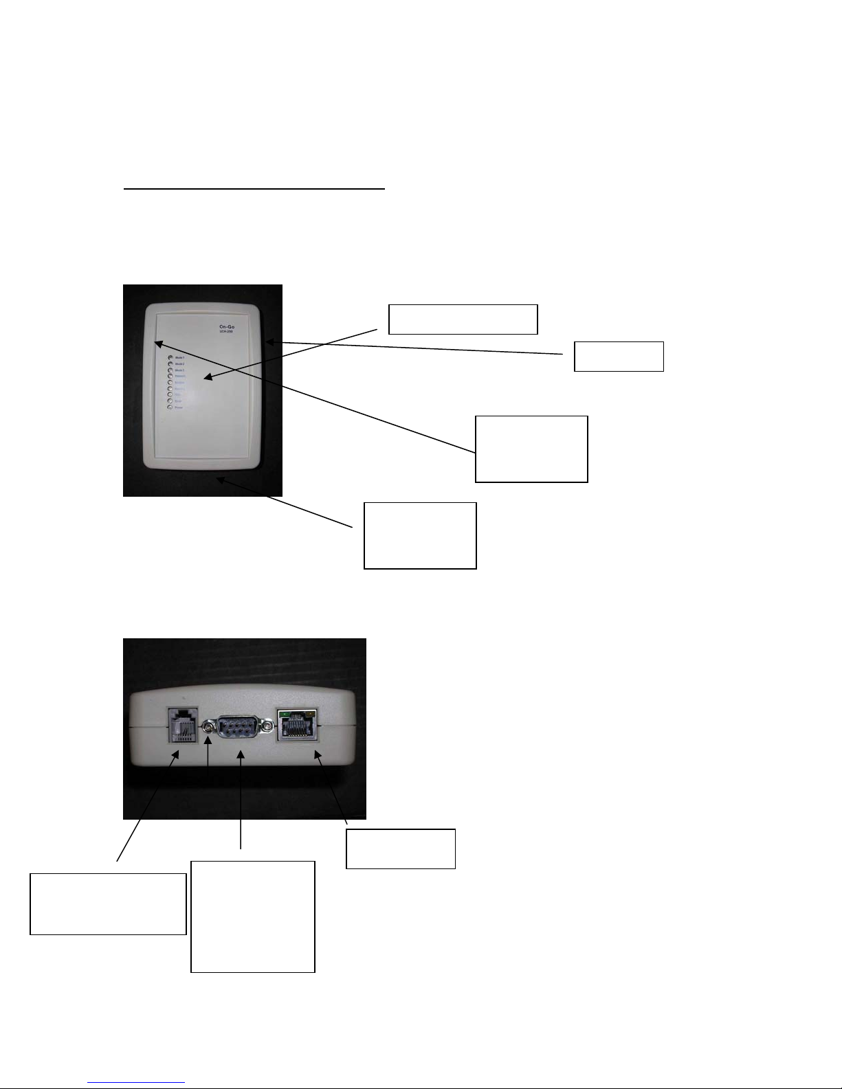
1. Top View
LED Indicators (1-8)
USB Port
Power Adapter
Jack,
12-30VDC
2. Front View
RJ11 Port (connect to
fax machine or data
modem)
PCCARD
connector
RJ45 Network
Port
Db9 (DTE) Serial
Port (connect to
wireless phone
data port)
Page 4

General
1.1 Concept
The Universal Communication Hub UCH-250 comes with multiple ports, Serial (DB9), Modem
(RJ11), Ethernet (RJ45), USB, and PCMCIA card slot. Each of the port can be configured as the
“Upstream” or “Network” port, and the remaining ports are then used as “Local” ports.
The primary function of the Universal Communication Hub is to act as a network router, device
interface and protocol converter. It allows all the local ports to operate different protocols and
sharing the same network access.
1.2 Product Version
There are two product versions. One is UCH-250 and the other is UCH-100. UCH-250 enables
all the ports, and provides:
• ANALOG Data and Fax capability
• Mobile to Mobile (Point to Point) Fax capability
• Network Routing (Ethernet or Wireless LAN)
• Data aggregation
UCH-100 has only Serial (DB9) port and Modem (RJ11) port enabled. It provides only data and
fax capability. In this document, the text marked GREEN means it only applies to UCH-250
only.
To check the product version number, simply press “#” key and the bottom line will indicate
whether you have UCH-250 or UCH-100.
1.3 LED and LCD Display
There are eight LEDs on the unit, marked 1-8. For most applications, the LEDs meaning are:
LED Function Off Slow Blink On
1 Mode 1
2 Mode 2
3 Mode 3 Link is being flow
controlled and
transmission speed is
automatically being
regulated
4 Connect Inactive Requesting
Upstream link
5 Modem RJ11 port not
ready
6 Pending PSTN
7 Wait
8 Error Inactive Incoming Fax
RJ11 port
detects
offhook or
RINGing
failed
Upstream link
established successfully
and connected
RJ11 port detects
onhook and ready for
use
A message for locally
attached device (fax)
was not able to be
delivered. Use the
Network-Queue
command to restart
Page 5

1.4 Configuration
The configuration of the device is broken down into three main groups, the UPSTREAM (network)
port, the LOCAL port, and APPLICATION.
The configurations are stored in a flash memory that the content is saved even when the power is
not available.
Each unit is preconfigured with a factory setting; the unit also comes with a few flavor of setting
that can be selected as the default setting by changing the DIP switch setting.
These are good templates to start with. In most cases, they should be sufficient. However, in the
case of some special occasion, one can always go into configuration (see detail users guide) to
change the values.
1.5 Updating Software with PCCard card or USB memory stick
The software in the unit is field upgradeable. The most reliable way is to use a PCCARD Storage
card (like Sandisk) or USB memory stick to transfer the files to the unit.
a. Get the latest software from On-Go
b. Copy the attached two files on a sandisk memory/storage card (8MB would be
sufficient)... the file names have to be uchkern.bin, uchapps.bin and uchcfg.bin (normally
on a PC)
c. Plug the card in the PCcard slot or USB port of the unihub
d. Power off and power back up the system to ensure the memory/storage card is properly
recognized by the system
e. Log on the Web access of Unihub
f. Select STATUS tab
g. Scroll down to OS + APP + CFG (for operating system, application and configuration)
NOTE: WARNING: Make sure you operate this with external DC power. Burning software in
FLASH takes a lot of electricity, and the system cannot RECOVER if the burning process aborts
in the middle (especially due to loss of power).
1.6 Updating Software from Serial Port
In some cases, where software needs to be updated, UCH-250 provides a field update capability.
This capability is only available from APPLICATION software version 1.6.x. This should only be
performed by qualified technical staff, otherwise it could cause irreversible damage to the
software and can only be repaired by the manufacturer.
In order to activate this, first valid software needs to be obtained. This filed needs to be stored on
a computer with XMODEM capability. Then the following instructions need to be followed
carefully:
a. Power up the UCH-100 and connect a phone/fax machine to RJ11 connector
b. Connect UCH-100 to the computer with the file via a CROSS-OVER (NULL
MODEM) cable
c. The computer needs to set the port to 115,200 baud rate, 8 bit, no parity and
hardware (RTS/CTS) flow control
d. Take the phone/fax machine offhook, enter ##9*PIN* then hangup (PIN is
provided only to qualified service provider technical staff)
e. The computer connected to UCH-100 over CROSS OVER serial cable should
display instruction:
Page 6

f. Select appropriate file to download and then activate XMODEM process (for
example, from HYPERTERMINAL, select TRANSFER->SEND FILE and enter
appropriate file name and choose XMODEM protocol).
g. After successful downloading the file, answer Y or y to start programming the
software to FLASH memory chip
h. Repeat this process for various files
i. When completing all the files, power cycle UCH-100 to activate the new software.
Example of how to update OPERATING SYSTEM: (as viewed on HYPERTERMINAL connecting
to UCH-100 SERIAL PORT)
Select:
0:exit
1:bootloader (armboot.bin)
2:operating system (kernel.bin)
3:applcation (romfs.bin)
4:configuration (cfg.bin)
Download: 2
...Ready to receive...
Å when seeing this character, should select TRANSFER/SEND
FILE/XMODEM protocol
(after file transfer completes)
Done: 988032 bytes received, write to flash (y/n)? y
OPERATING SYSTEM:
UNLOCKING flash: status 0
ERASING flash: status 0
PROGRAMMING flash: status 0
VERIFY flash at 180000: status 0
LOCKING flash: status 0
Select:
0:exit
1:bootloader (armboot.bin)
2:operating system (kernel.bin)
3:applcation (romfs.bin)
4:configuration (cfg.bin)
Download: 0
Bye...
At this time, it is necessary to restart the system for new software to take effect. It is very
important to make sure software is loaded properly… otherwise, the system will not come
back up again.
1.7 Diagnosis Capability
The system is capable of dumping out some internal information for diagnosis. This is only used
by authorized technical personnel.
1 Use web browser to access UCH
2 Press LOG tab
3 The system will dump out the configuration in unihub.cfg and log in unihub.log. They can
then be viewed on a PC for further diagnosis
Page 7

2 Application
2.1 Fax
2.1.1 Store and Forward Fax
Store and forward fax means the fax is stored and relayed over data network. This mechanism is
typically preferred when
a. The network bandwidth does not support fax protocol/encoding
b. The network connectivity is not consistent/reliable. If a fax has to be sent
multiple times before it can be successfully delivered, then Store and forward is
the more economical method.
2.1.1.1 Notification
The first step of configuration of store-and-forward faxing is to determine what type of notification
is to be used.
Notification is used for two purposes:
c. Indicating the delivery status (Mobile Originated Fax)
d. Indicating the availability of incoming fax (Mobile Terminated Fax)
Several notification mechanisms are supports:
1. GSM style SMS: the SMS message length should be able to support 100+
characters. The Gateway will send the entire status message in the SMS.
2. Short SMS: for network with shorter SMS message length capability, this
mechanism is used to simply “wake up” the Universal Communication Hub and
the Universal Communication Hub will attempt to establish a data call to the
Gateway to pick up the status
3. Direct Call: For system that does not support SMS, this mechanism is used for
the Gateway to place a short data call to wake up the Universal Communication
Hub
The appropriate notification mechanism needs to be provisioned at the central Gateway Business
Management System interface to allow proper operation.
2.1.1.2 Mobile Originated Fax
Mobile Originated fax allows an off-the-shelf G3 fax machine to be used to send documents over
the data network. After connecting the G3 fax machine to the RJ11 modem port, wait for the LED
#2 to be ON (indicating modem port is ready), then take the fax offhook, and dial the number in
the format: COUNTRY_CODE + NUMBER. Do not dial any prefix like 00 or 011, the system will
handle that automatically.
2.1.1.3 Mobile Terminated Fax
Mobile terminated fax is automatic. When the user subscribes to a service plan, a “MAILBOX”
number will be assigned to the unit. When a fax is sent to that MAILBOX number (this number is
not the same as the mobile data number), a notification is sent to the unit and the unit will connect
to the Gateway to pick up that message. When the message is completely downloaded to the
unit, it will simply RING the fax machine and print the message out. On-Go service can support
mobile terminated fax originated from a fax machine or an email client (ie When an email is sent
to [email protected]
, it is automatically converted and sent to the UNIHUB
as a fax).
If for some reason the fax is not powered on, out of paper or simply not connected, the user has
to use the Message Management to get the fax to be printed.
Page 8
2.1.1.4 Point to Point Fax
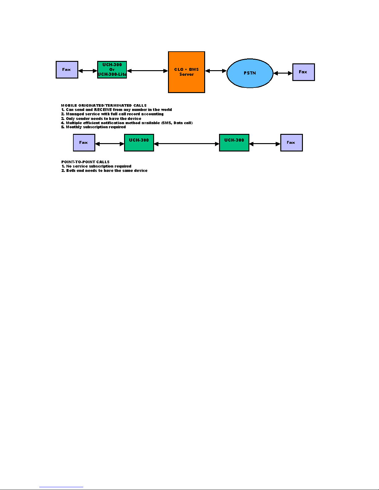
For both Mobile Originated Fax and Mobile Terminated Fax, a service plan has to be in place for
the function to work. However, in the case where someone wants to only send faxes to a few
KNOWN parties, and both the senders and receivers are equipped with UCH-250, Point to point
fax can be advantageous. The benefits are:
a. No service plan required
b. (Perceived) privacy
However, each receiver also needs to have a Universal Communication Hub in order for this
mode to work, which limits the reach of the transmission significantly.
To activate the Point-to-point feature, a few parameters are relevant:
1. [APPLICATION/SF-FAX] local address: this is the address that the remote will use to call
back for acknowledgement
2. [APPLICATION/SF-FAX] P2P type – Set to LOCAL if the call is to be sent to a UCH-250
that has a fax machine connected to RJ11 port. If this is set to OFF, P2P function will not
work.
3. [APPLICATION/SF-FAX] P2P pattern – This is used to determine whether the call is P2P.
If P2P type is set and P2P pattern is 55, then any call starts with 55 will be considered a
P2P call.
4. [APPLICATION/SF-FAX] P2P pattern strip – If this is set to Yes, the pattern will be
striped off first before being used as address.
5. [APPLICATION/SF-FAX] P2P prefix – This prefix is attached in front of the dial number
AFTER the P2P pattern stripping is processed to form the final number.
Other parameters that are important:
1. [UPSTREAM/SERIAL/incoming wait] – This has to be non-zero, otherwise the unit will
not wait for incoming call
2. [UPSTREAM/INITIAL CALL BYPASS] – Set it to Yes, otherwise the unit will continue to
try to access the gateway, and if service plan is not available, the access will fail
2.1.1.5 IP based Point to Point Fax
In the narrowband environment, it is easy to establish circuit connection from one terminal to
another by simply placing a direct data call. However, when operating in the IP environment,
where the IP address is not public and may change from time to time, it is more challenging to
offer Point-to-Point transmission feature.
Page 9

On-Go UNIHUB overcomes this challenge by delivering an elegant solution using PROXY
REDIRECT technology. With this solution, the network topology is transparent to users, and
operation is as simple as narrow band network.
The solution centered around one addition UNIHUB (PROXY) that behaves like a traffic director
for the close network. Each UNIHUB registers with this UNIHUB (PROXY) and report its own
VIRTUAL number. When transmission is required to communication with a particular virtual
number, UNIHUB (PROXY) will provide the necessary mean for the originating UNIHUB to reach
the appropriate terminating UNIHUB.
The only requirement is that the UNIHUB that behaves as the PROXY needs to have a FIXed IP
address. Because the network is IP, there is no requirement for all the terminals to be on the
same type of network, as long as there is communication path between all the terminals. For
example, some of the UNIHUBs may be connected to the mobile/satellite terminals, when some
can be connected to the land-line network.
Configuration:
UNIHUB acting as PROXY REDICTOR
UPSTREAM -> APPLICATION need to be set to P2P-PROXY
UNIHUB acting as CLIENT NODES
APPLICATION -> SFFAX -> P2P PROXY needs to point to the known FIXED IP address
of the UNIHUB PROXY REDIRECTOR
APPLICATION -> SFFAX -> P2P PROXY PASSWORD needs to be the same as the
SYSTEM password of UNIHUB PROXY REDIRECTOR
APPLICATION -> SFFAX -> LOCAL ADDRESS needs to be configured as the VIRTUAL
address of the node (note: be careful not to have duplicate UNIHUB with the same address within
the same network)
Other Point-to-point related parameters that should be configured just like the narrowband type of
Point-to-point setup are:
APPLICATION -> SFFAX -> P2P PATTERN needs to be configured to the dialing prefix
that would trigger point-to-point processing (ie otherwise, the calls will always be considered
SERVER based transmission)
2.1.2 Message Management
The messages in the Universal Communication Hub are organized in several groups. When the
message is ready to go out through the network, it is in the Outgoing Queue. When the message
is sent over the network and acknowledgement has not been received yet, it is in Ackwait Queue.
After the acknowledgement is received indicating delivery attempts failed (or when the timer
expired without receiving acknowledgment), it is put in the Failed Queue.
When incoming message is received from the network, it is put in the Incoming queue. If it
cannot be printed for some reason (fax is disconnected, fax is out of paper, fax is turned off), it
will be moved to FromNetworkFail Queue.
All of these messages in various queues can be managed by pressing the NETWORK action key
(6).
2.2 Data
Page 10

UCH provides a capability to transport ANALOG data across digital network. If there are analog
data (for example, ATM machines, credit card terminal, utility meters, or computer with analog
modem) need to be able to interface with digital data network, UCH can provide the ideal
interface connectivity.
UCH provides the telephony interface (dialtone, loop current) and modulation/demodulation to
extract the information content from the interface and then package the data over digital network
pipe to a server with interconnectivity with PSTN to deliver the information to the end points.
2.3 GPS
With the popularity of GPS, GPS receivers can be bought on the market fairly inexpensively. The
Universal Communication Hub can interface to a NMEA based GPS receiver (for example:
http://www.rayming.com/products/tripnav_tn200.htm), either the USB based or Compactflash
based, process the information, and communicate that information to configured destination. This
allows maritime/trucking fleet companies to manage their assets and monitor the position of each
vessels/vehicles.
The main configuration related to this application is in the APPLICATION/GPS block. There are
six relevant parameters:
• Proxy: this is the destination that the GPS position information will be sent to (email
address)
• Type: SMS or Buffer (SMS needs to be capable of handling about 90 characters)
• Interval: This is the interval that the data is being sent (either SMS or buffer)
• Buffering: Type of data to store. The unihub can filter out bad data, invalid signal data,
etc.
• Expiration: If the data cannot be sent within this amount of time, it is discarded because it
is stale.
• Limit: In polling mode, this parameter dictates how much GPS data to store.
Another parameter that is important is the SMSC address in the UPSTREAM/SERIAL
configuration. For iridium, this is *2. This is used for SMS type of GPS data reporting.
Also, while the GPS receiver is plugged in to the Universal Communication Hub, you can view the
data by pressing USB (7) or CFCARD (4) action key, and select ShowGPS. There is another
command SendGPS which manually trigger the Universal Communication Hub to send latest
GPS data to the network.
The format of the GPS information includes:
Unihub rcv_time,
offset from last unihub gps data time,
unihub gps message counter,
current year based on GPS receiver message
current month based on GPS receiver message
current day based on GPS receiver message
current hours based on GPS receiver message
current minutes based on GPS receiver message
current seconds based on GPS receiver message
current latitude based on GPS receiver message
current longitude based on GPS receiver message
current altitude based on GPS receiver message
current speed based on GPS receiver message
Page 11

current track based on GPS receiver message
current magnetic variation based on GPS receiver message
current course based on GPS receiver message
current GPS mode based on GPS receiver message
current GPS status based on GPS receiver message
current GPS satellite # based on GPS receiver message
current GPS satellite in view based on GPS receiver message
2.4 Webcam
UCH can be used as the platform for remote WEBCAM image source. It is capable of interfacing
with many off-the-shelf USB based webcam and provide either SNAPSHOT or video streaming
thru the network. (see view.on-go.com for example).
2.5 Networking
2.5.1 Serial
The most typical setup use of this port as the network port. The serial port should be connected
to a wireless modem (or any wireless phone that has data capability).
The connection protocol being established over the serial port is PPP. In some cases, the
network has a Remote Access Server (RAS) that allow the Universal Communication Hub to get
on ramp to the Internet. In some cases, the wireless terminal (mobile phone) can handle that
function (for example, GPRS phone). In other cases, an ISP account is needed for the
connection to be established.
The configuration allows different type of connectivity handshaking (PAP, CHAP) to be
established.
2.5.2 Ethernet
Ethernet can be either the network port or the local port. If it is the network port, it is used to
interface to the external network. In this case, the Ethernet port can support DHCP and static IP
address configuration. DHCP mode means the unit will obtain the network address from DHCP
server somewhere else.
As the local port, the Ethernet port can also support DHCP and Static IP address configuration.
But in this case, the Universal Communication Hub acts as the DHCP server and pass out IP
address assignment.
2.5.3 Wireless LAN
Similar to the Ethernet, the Wireless LAN port can be either a network port or a local port.
As a local port, the Universal Communication Hub can behave like a Wireless LAN Access Point
if a PRISM based WIFI compact flash card is plugged in the compact flash slot. Most of the CF
based WIFI card are PRISM chipset based, like DLINK DCF-660W. In addition to the Ethernet
type of configuration, this port needs ESSID, WEP and Channel configuration. The default
ESSID is uniHub and WEB is off and Channel is 6.
As the network port, the Universal Communication Hub can communicate with an Access Point
and use the link as the network link.
Page 12

2.5.4 ON DEMAND dialing
On demand dialing (AUTO CONNECT) is a feature that provides a SEAMLESS connectivity
without constantly connected on the network. This is a powerful feature in the environment where
connection charge is based on TIME instead of DATA PACKETS.
When this feature is activated (CONFIG->UPSTREAM->SERIAL->AUTO CONNECT), the
connection will be established automatically when an IP packet that cannot be reached. The
connection will be dropped automatically when there is no activities for certain amount of time.
With this feature, the user does not have to SPECIFICALLY connect to or disconnect from the
network manually.
2.5.5 Traffic Aggregation
From time to time, if one data link is not providing sufficient bandwidth, the Universal
Communication Hub can aggregate multiple data paths to provide higher aggregated bandwidth.
The aggregation is handled behind the scene so from the users point of view, it is no different
from single link, except it is faster.
The requirements for traffic aggregation are:
a. A multi-serial port USB device: There are several on the market, for example In-Out-
Network EDGEPORT is a popular source for providing USB based multi-serial port.
When using this mechanism, simply select the USB port as the UPSTREAM (network)
port and configure the ports to be multilink serial port.
b. The Remote Access Server (RAS) on the other end has to be multilink (MLPPP)
compatible. This is an industry standard protocol, so most ISPs RAS do support this.
In the data aggregation mode, one of the serial link has to be designated as the ANCHOR link.
That is the link that SMS notification will be used, and the data number associated with this
anchor link is the number for the entire link set.
Page 13

2.6 LED Lights
The UCH is equipped with eight (8). The LED lights provide an indicator on the status
of various operations of the UCH by changing its state between Off, Blinking Slow,
Blinking Fast, and On. The table below indicates what each LED and its respective
status represents.
LE
Function Off Slow Blink On
D
1 Mode 1
2 Mode 2
3 Mode 3 Link is being flow
controlled and
transmission speed
is automatically
being regulated
4 Connect Inactive Requesting
Upstream
link
Upstream link
established
successfully and
connected
5 Modem RJ11 port not
ready
RJ11 port
detects
offhook or
RJ11 port detects
onhook and ready
for use
RINGing
6 Pending PSTN
7 Wait
8 Error Inactive Incoming
Fax failed
A message for
locally attached
device (fax) was not
able to be delivered.
Use the NetworkQueue command to
restart
2.7 Local Commands
The user can command UCH-250 to perform certain tasks or retrieve internal status and
report. This command is performed through a tone-based telephony device (such as a
phone or fax machine). To enter the command, simply take the attached telephony
device off hook, enter the key sequence and then hang up.
All the commands start with two “#” keys. The following is the supported commands.
The only command user needs to remember is “###”.
KEY COMMAND
Page 14

SEQUENCE
##1 Connectivity command – requesting UCH-250 to connect to Network
and/or On-Go server (##1#0# for connecting to On-Go Server, ##1#1# for
connecting to the Internet, ##1#2 for disconnecting from the Internet
##2 Simulated Remote Request command
##3 Reserved
##4 Retry incoming command – requesting UCH-250 to retry printing
incoming messages (need to have a fax machine attached to the RJ11
phone port) ##4#0 will clear the failed message queue. ##4#1 will reprint
the inbound (mobile terminated) faxes that failed before, ##4#2 will
retransmit those outbound (mobile originated) faxes
##5 Prepaid command - ##5 to inquire balance, ##5#cardnumber#pin# to top
up
##6 Print status command – requesting UCH-250 to print internal status (need
to have a fax machine attached to the RJ11 phone port)
##7 Show Status command – requesting UCH-250 to print internal software
version and DIP switch setting, mostly for diagnostic purpose (need to
have a fax machine attached to the RJ11 phone port)
##8 Show Config command – requesting UCH-250 to print internal
configuration setting, mostly for diagnostic purpose (need to have a fax
machine attached to the RJ11 phone port)
##9 SERIAL DOWNLOAD command (only for qualified service provider
technical staff)
##0 Reserved for future commands
##* System Log command – requesting UCH-250 to print system log, mostly
for diagnostic purpose (need to have a fax machine attached to the RJ11
phone port)
### HELP command– requesting UCH-250 to print a command help summary
(need to have a fax machine attached to the RJ11 phone port)
Page 15
2.8 DIP switches
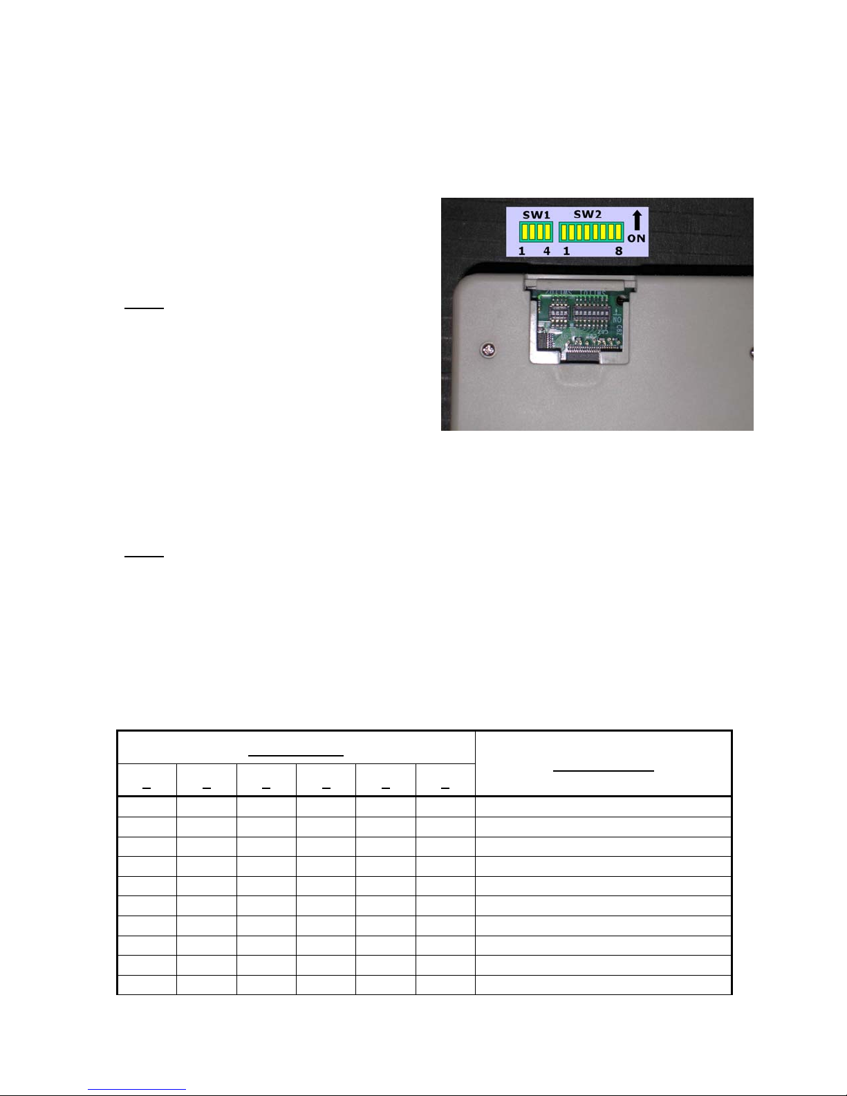
DIP switches are located on the bottom of the board that can be accessed without opening
the enclosure. There are two group of switches, one has four (SW1) and the other has
eight switches (SW2).
SW1:
POSITION 1: – normal operation (off for
configuration only which unit has
192.168.1.99 default address)
POSITION 2: – polling off
POSITION 3: – print delivery report (for
store and foward-fax)
POSITION 3: – quick connect (for realtime operation)
POSITION 4: – bypass initial contact to server
SW2: profile selection
POSITION 1: USE DEFAULT CONFIGURATION (This is useful when the
configuration is changed and user can no longer access the UCH web
server); ignore the rest of SW2 setting
POSITION 2: USE STORED CONFIGURATION (This is useful when POSITION 3-8
are to be ignored)
POSITION 3-8: Use pre-built configuration
SW2 Position
3 4 5 6 7 8
OFF OFF OFF OFF OFF ON IRIDIUM 9505
OFF OFF OFF OFF ON OFF IRIDIUM 9500
OFF OFF OFF OFF ON ON GLOBALSTAR 1600
OFF OFF OFF ON OFF OFF GLOBALSTAR fixed
OFF OFF OFF ON OFF ON GLOBALSTAR Cellular
OFF OFF OFF ON ON OFF Aces FG190G
OFF OFF OFF ON ON ON Thuraya
OFF OFF ON OFF OFF OFF SERIAL AT&T Wireless GPRS
OFF OFF ON OFF OFF ON SERIAL T-MOBILE GPRS
OFF OFF ON OFF ON OFF SERIAL Nextel GPRS
Configuration
Page 16

OFF OFF ON OFF ON ON SERIAL Verizon GPRS
OFF OFF ON ON OFF OFF SERIAL Cingular GPRS
OFF OFF ON ON OFF ON SERIAL Sprint GPRS
OFF OFF ON ON ON OFF USER CONFIGURATION 1
OFF OFF ON ON ON ON USER CONFIGURATION 2
OFF ON OFF OFF OFF OFF SERIAL Cincinati Bell GPRS
OFF ON OFF OFF OFF ON USB GLOBALSTAR
OFF ON OFF OFF ON OFF USB AT&T Wireless GPRS
OFF ON OFF OFF ON ON USB T-MOBILE GPRS
OFF ON OFF ON OFF OFF USB NEXTEL GPRS
OFF ON OFF ON OFF ON USB VERIZON GPRS
OFF ON OFF ON ON OFF USB CINGULAR GPRS
OFF ON OFF ON ON ON USB SPRINT GPRS
OFF ON ON OFF OFF OFF ETHERNET DHCP
OFF ON ON OFF OFF ON ETHERNET STATIC
OFF ON ON OFF ON OFF PCCARD AT&T Wireless GPRS
OFF ON ON OFF ON ON PCCARD T-MOBILE GPRS
OFF ON ON ON OFF OFF PCCARD Nextel GPRS
OFF ON ON ON OFF ON PCCARD Verizon GPRS
OFF ON ON ON ON OFF PCCARD Cingular GPRS
OFF ON ON ON ON ON PCCARD Sprint GPRS
ON OFF OFF OFF OFF OFF ETHERNET PPPOE
ON OFF OFF OFF OFF ON ETHERNET INMARSAT HNS
 Loading...