

Page 1
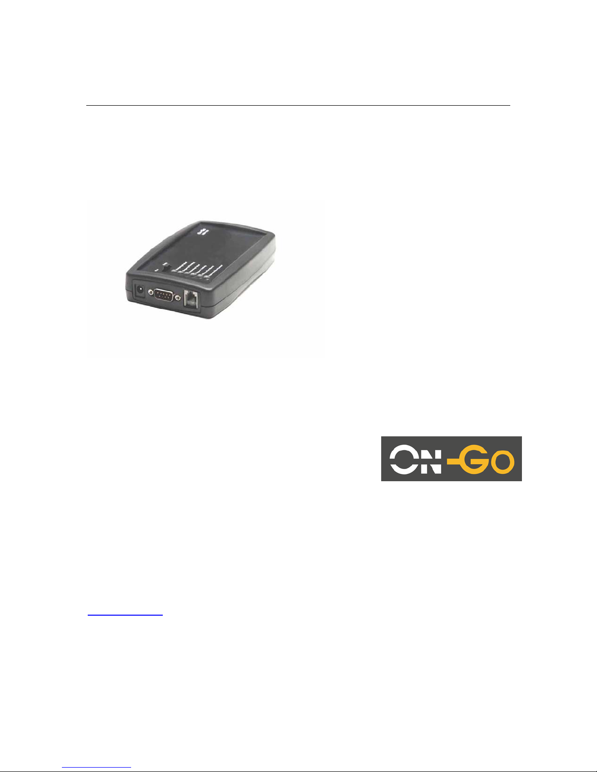
Universal Communication Hub UCH-100
Quick Start Guide
On-Go Inc.
P.O.Box 341726
Bethesda, MD 20817
USA
Tel: +1.301.765.8030
Fax: +1.301.765.8031
www.on-go.com
Note: The information in this document applies to UCH-100 product.
Revision: 1.4
Revision Date: 9/5/2005
Page 2

)
O
Universal Communication Hub (UCH-100) Interface
1. Front View
AC Adapter
Jack
Db 9 Serial
Port (connect
to satellite
phone data
cable
RJ11 Port (connect
to fax machine or
data modem)
2. Top View
LED Indicators (1-
Three position
P
WER
3. Battery Orientation (Please ensure proper battery orientation to avoid damaging the
unit)
Page 3

1.1 General Concept
The Universal Communication Hub UCH-100 comes with two ports, Serial (DB9) and Modem
(RJ11). It simply provides telephony interface to data/fax devices over digital network.
Equipment such as fax machine, credit card terminal, security alarm, data modem, which all uses
RJ11 interface and requires fixed line telephony network, UCH-100 offers an alternative
mechanism to utilize these devices in environment where fixed line telephony network is not
readily available.
2 Application
2.1 Fax
3 Store and Forward Fax
Store and forward fax means the fax is stored and relayed over data network. This mechanism is
typically preferred when
a. The network bandwidth does not support fax protocol/encoding
b. The network connectivity is not consistent/reliable. If a fax has to be sent
multiple times before it can be successfully delivered, then Store and forward is
the more economical method.
To enable the data capability, turn on the unit by pushing the switch to FAX.
3.1.1.1 Notification
The first step of configuration of store-and-forward faxing is to determine what type of notification
is to be used.
Notification is used for two purposes:
c. Indicating the delivery status (Mobile Originated Fax)
d. Indicating the availability of incoming fax (Mobile Terminated Fax)
Several notification mechanisms are supports:
1. GSM style SMS: the SMS message length should be able to support 100+
characters. The Gateway will send the entire status message in the SMS.
2. Short SMS: for network with shorter SMS message length capability, this
mechanism is used to simply “wake up” the Universal Communication Hub and
the Universal Communication Hub will attempt to establish a data call to the
Gateway to pick up the status
3. Direct Call: For system that does not support SMS, this mechanism is used for
the Gateway to place a short data call to wake up the Universal Communication
Hub
The appropriate notification mechanism needs to be provisioned at the central Gateway Business
Management System interface to allow proper operation.
3.1.1.2 Mobile Originated Fax
Mobile Originated fax allows an off-the-shelf G3 fax machine to be used to send documents over
the data network. After connecting the G3 fax machine to the RJ11 modem port, wait for the LED
#2 to be ON (indicating modem port is ready), then take the fax offhook, and dial the number in
Page 4

the format: COUNTRY_CODE + NUMBER. Do not dial any prefix like 00 or 011, the system will
handle that automatically.
3.1.1.3 Mobile Terminated Fax
Mobile terminated fax is automatic. When the user subscribes to a service plan, a “MAILBOX”
number will be assigned to the unit. When a fax is sent to that MAILBOX number (this number is
not the same as the mobile data number), a notification is sent to the unit and the unit will connect
to the Gateway to pick up that message. When the message is completely downloaded to the
unit, it will simply RING the fax machine and print the message out.
If for some reason the fax is not powered on, out of paper or simply not connected, the user has
to use the Message Management to get the fax to be printed. (see LOCAL COMMAND ##4).
3.2 Data
To enable the data capability, turn on the unit by pushing the switch to DATA.
Once in data mode, a data modem can be connected to the modem port. The user must dial the
EXACT same number that the call is to be established, including the prefixes. The Universal
Communication Hub will establish a data call based on that number.
Page 5

4 Configuration and Status
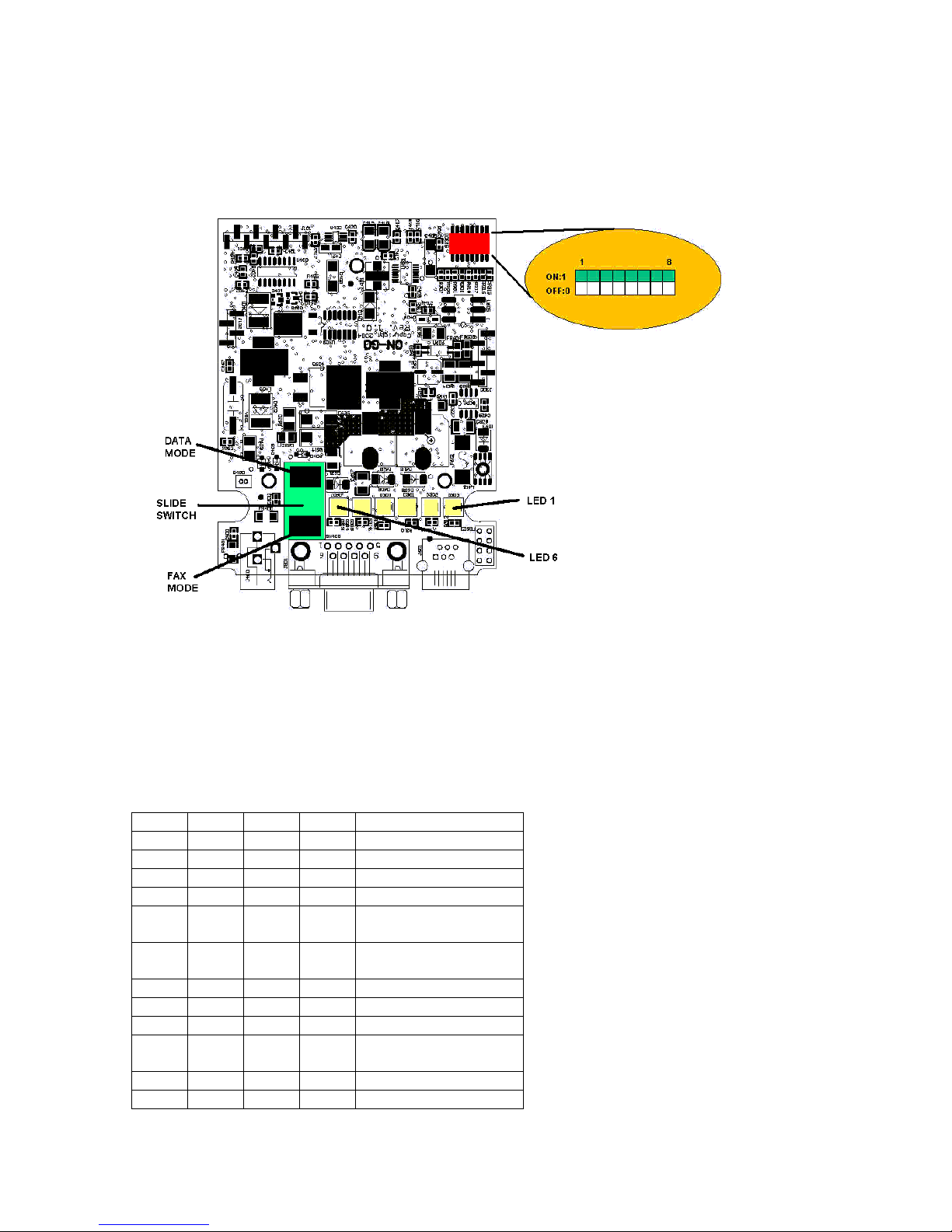
The functionality of the UCH-100 is dictated by TWO settings, the SLIDE SWITCH setting and the
DIP switch setting. The SLIDE switch setting position determines whether UCH-100 will be
operating in DATA or FAX mode; this switch can be accessed easily. The DIP switch is not
exposed externally and should normally be set by the Service Provider only. The DIP switch
position will dictate the personality of the UCH-100.
4.1 LED indication
The UCH-100 has 6 LEDs that indicate the operational status of the unit. The LEDs status are:
LED Function Off Slow Blink Fast Blink On
1 Monitors
Upstream
link
Inactive Requesting
Upstream link
Connecting to
Upstream link
Upstream link
established
successfully and
connected
2 Monitors
Phone
Modem
interface
Ready to
place
outgoing call
on local
Placing
outgoing call on
local PSTN
Ready to send
fax over
upstream link
Accepting fax to be
sent over upstream
link
PSTN
3 Monitors
Serial
interface
Configured
for Serial
Port use
Link is being flow
controlled and
transmission speed
is automatically
being regulated
4 Incoming
Fax failed
Inactive Incoming Fax
Not Applicable Messages for locally
failed
attached device (fax)
was not able to be
delivered. Use the
Network-Queue
command to restart
5 Outgoing
Pending
Outgoing
message
pending
Outgoing
message
transferred but
awaiting for
acknowledgeme
nt
6 Outgoing
Failed
No failure,
DC power
Outgoing
Message Failed
DC POWER
Outgoing
Message Failed
BATTERY
No failure
BATTERY
POWER
Page 6

4.2 LOCAL commands
Though the UCH-100 has no built-in keypad, the user can still command UCH-100 to perform
certain tasks or retrieve internal status and report. This command is performed through a tonebased telephony device (such as a phone or fax machine). To enter the command, simply take
the attached telephony device off hook, enter the key sequence and then hang up.
All the commands start with two “#” keys. The following is the supported commands. The only
command user needs to remember is “###”.
KEY
COMMAND
SEQUENCE
##1 Connectivity command – requesting UCH-100 to connect to Network and/or On-
Go server (##1#0# for connecting to On-Go Server, ##1#1# for connecting to the
Internet, ##1#2 for disconnecting from the Internet
##2 Reserved
##3 Reserved
##4 Retry incoming command – requesting UCH-100 to retry printing incoming
messages (need to have a fax machine attached to the RJ11 phone port)
##5 Prepaid command - ##5 to inquire balance, ##5#cardnumber#pin# to top up
##6 Print status command – requesting UCH-100 to print internal status (need to have
a fax machine attached to the RJ11 phone port)
##7 Show Status command – requesting UCH-100 to print internal software version
and DIP switch setting, mostly for diagnostic purpose (need to have a fax machine
attached to the RJ11 phone port)
##8 Show Config command – requesting UCH-100 to print internal configuration
setting, mostly for diagnostic purpose (need to have a fax machine attached to the
RJ11 phone port)
##9 SERIAL DOWNLOAD command (only for qualified service provider technical staff)
##0 Reserved for future commands
##* System Log command – requesting UCH-100 to print system log, mostly for
diagnostic purpose (need to have a fax machine attached to the RJ11 phone port)
### HELP command– requesting UCH-100 to print a command help summary (need
to have a fax machine attached to the RJ11 phone port)
Page 7
4.3 DIP SWITCH SETTINGS
DIP switches are located on the top of the board close to the battery compartment.
FAX MODE:
5 6 7 8
OFF OFF OFF OFF IRIDIUM 9505
OFF OFF OFF ON IRIDIUM 9500
OFF OFF ON OFF GLOBALSTAR 1600
OFF OFF ON ON GLOBALSTAR fixed
OFF ON OFF OFF GLOBALSTAR
Celluar
OFF ON OFF ON IRIDIUM CREW
CALLING
OFF ON ON OFF Aces FG190G
OFF ON ON ON Thuraya
ON OFF OFF OFF Reserved
ON OFF OFF ON AT&T Wireless
GPRS
ON OFF ON OFF T-MOBILE GPRS
ON OFF ON ON Nextel GPRS
Page 8

ON ON OFF OFF Verizon GPRS
ON ON OFF ON Cingular GPRS
ON ON ON OFF Sprint GPRS
ON ON ON ON USER
CONFIGURATION
4
OFF No Printing
ON Print
Acknowledgement
2 3
OFF OFF Dialtone length 0.75 s
OFF ON Dialtone length 1.5 s
ON OFF Dialtone length 1.2 s
ON ON Dialtone length 0.5 s
1
ON Bypass initial connect
OFF Perform initial
connect
DATA MODE:
5 6 7 8
OFF OFF OFF OFF IRIDIUM 9505
OFF OFF OFF ON IRIDIUM 9500
OFF OFF ON OFF GLOBALSTAR 1600
OFF OFF ON ON GLOBALSTAR fixed
OFF ON OFF OFF GLOBALSTAR
Celluar
OFF ON OFF ON Reserved
OFF ON ON OFF Aces FG190G
OFF ON ON ON Thuraya
ON OFF OFF OFF Reserved
ON OFF OFF ON AT&T Wireless
GPRS
ON OFF ON OFF T-MOBILE GPRS
ON OFF ON ON Nextel GPRS
ON ON OFF OFF Verizon GPRS
ON ON OFF ON Cingular GPRS
ON ON ON OFF Sprint GPRS
ON ON ON ON USER
CONFIGURATION
Page 9

4
ON Quick Connect
OFF No Quick Connect
1 2 3
OFF OFF OFF Auto
OFF OFF ON 1200 bps
OFF ON OFF 2400 bps
OFF ON ON 4800 bps
ON OFF OFF 9600 bps
ON OFF ON 19200 bps
ON ON OFF 38400 bps
ON ON ON
Page 10

4.4 SERIAL CONFIGURATION UTILITY
In some cases, where preloaded configuration templates do not provide sufficient flexibility, UCH100 offers EXPERT users a way to enter/modify more specific configuration parameters via the
SERIAL port.
There are TWO user definable configuration templates, one is when the power switch is set to
FAX mode and one is when power switch is set to DATA mode. To enter the configuration mode,
all the DIP switches should be turn to ON. Depending on the position of the power switch, the
corresponding configuration template will be used. To activate the user defined configuration
template after the change, simply turn OFF the unit, toggle the DIP switch position from ON to
OFF and then turn back on the unit.
To connect the computer/terminal to the SERIAL PORT, a NULL MODEM and a GENDER
CHANGER must be used, as both end of the connection are in DTE mode. The setting on the
computer/terminal end should be 38400 bps, 8 bit, no parity, no hardware/software flow control.
The users must be familiar with UCH-300 configuration structure. UCH-300 comes with a 16-key
keypad. The command input mapped to the keys are:
UCH-300 keypad UCH-100 command input
0 – 9, *, # 0 – 9, *, #
CONFIG/SELECT M
NEXT >
PREVIOUS <
CANCEL C
In addition, two other commands are available:
Write out configuraiton W
Quit Q
A typical configuration session includes the following steps:
1. TURN OFF the unit
2. SWITCH all DIP switch position to ON.
3. Connect a computer to the SERIAL PORT with NULL modem and GENDER changer in
between.
4. TURN ON the unit
5. Select a known template as the baseline by choosing a factory supplied configuration
template as the baseline.
6. Make modifications
7. Use ‘W’ command to write out the configuration in the FLASH. This may take a few
minutes.
8. TURN OFF the unit.
9. TOGGLE DIP switch POSITION 1 to OFF position
10. TURN BACK ON the unit.
Since the configuration can drastically change the behavior of the unit, we do not recommend
using this feature.
Page 11

4.5 SOFTWARE UPDATE facility
In some cases, where software needs to be updated, UCH-100 provides a field update capability.
This capability is only available from APPLICATION software version 1.6.x. This should only be
performed by qualified technical staff, otherwise it could cause irreversible damage to the
software and can only be repaired by the manufacturer.
In order to activate this, first valid software needs to be obtained. This filed needs to be stored on
a computer with XMODEM capability. Then the following instructions need to be followed
carefully:
a. Power up the UCH-100 and connect a phone/fax machine to RJ11 connector
b. Connect UCH-100 to the computer with the file via a CROSS-OVER (NULL
MODEM) cable
c. The computer needs to set the port to 115,200 baud rate, 8 bit, no parity and
hardware (RTS/CTS) flow control
d. Take the phone/fax machine offhook, enter ##9*PIN* then hangup (PIN is
provided only to qualified service provider technical staff)
e. The computer connected to UCH-100 over CROSS OVER serial cable should
display instruction:
f. Select appropriate file to download and then activate XMODEM process (for
example, from HYPERTERMINAL, select TRANSFER->SEND FILE and enter
appropriate file name and choose XMODEM protocol).
g. After successful downloading the file, answer Y or y to start programming the
software to FLASH memory chip
h. Repeat this process for various files
i. When completing all the files, power cycle UCH-100 to activate the new software.
Example of how to update OPERATING SYSTEM: (as viewed on HYPERTERMINAL connecting
to UCH-100 SERIAL PORT)
Select:
0:exit
1:bootloader (armboot.bin)
2:operating system (kernel.bin)
3:applcation (romfs.bin)
4:configuration (cfg.bin)
Download:
...Ready to receive...
Å when seeing this character, should select TRANSFER/SEND
FILE/XMODEM protocol
(after file transfer completes)
Done: 988032 bytes received, write to flash (y/n)?
OPERATING SYSTEM:
UNLOCKING flash: status 0
ERASING flash: status 0
PROGRAMMING flash: status 0
VERIFY flash at 180000: status 0
LOCKING flash: status 0
Select:
0:exit
1:bootloader (armboot.bin)
2:operating system (kernel.bin)
3:applcation (romfs.bin)
2
y
Page 12

4:configuration (cfg.bin)
Download:
0
Bye...
At this time, it is necessary to restart the system for new software to take effect. It is very
important to make sure software is loaded properly… otherwise, the system will not come
back up again.
 Loading...