

Page 1
OWNER’S MANUAL
An earth leakage or residual current protection device must be
fitted to all installations.
Should you the installer or owner be unfamiliar with the correct
installation or operation of this type of equipment you should contact
the distributor/manufacturer for the correct advice before proceeding
with the installation or operation of the product.
Pantera Pool Pumps
Page 2

Technologically advanced solutions for
moving and treating water in the Home,
Garden, Pool and Spa.
Innovative Stock and Crop water
management solutions for Primary
Industries.
Water movement products for Building
services, Emergency services and
Original Equipment Manufacturers.
Relax - you’ve bought an ...
Congratulations on your decision to purchase an Onga product.
Onga is one of the best know brands in its field, with a proud local
and international reputation.
Onga is a brand for reliability, value for money and technological
innovation. You will find Onga product wherever people need to
move water in 3 broad markets covering:
1
Page 3

1. Continual Product Improvement
We employ the best engineers both in Australia and
around the world to develop new and better ways to
take water further.
2. Operational Excellence
There is only one standard that we set ourselves for both
product quality and the quality of our service. That standard
is excellence... to have no-one better than us at what we
do... nothing short of that is acceptable. Our commitment to
quality is reinforced with our ISO 9001.
3. A Fair Price
Onga products are neither the cheapest nor the most
expensive in their field. Our products do, on the other hand,
always represent very good value for money; they always
have and they always will.
4. Our Team of Dealers
The hand picked authorised Onga dealer network throughout
Australia and worldwide are second to none. We invest
considerable time and resources training and supporting
them through the Onga Training Academy.
2
Page 4

Table of Contents
Page
Safety
4
Installation 5
Operation 6
Service & Maintenance 8
Removal of Pump for Servicing 9
Parts Diagram 10
Troubleshooting 11
3
Page 5

4
Safety
IMPORTANT!
The operator must be provided with this owner’s manual. This must be read before
operation and followed during operation.
These instructions are a guide only. Users not familiar with pool equipment should seek
advice from suitably qualified persons with experience in pool equipment installation.
The Pantera range of pool pumps have been specifically designed to incorporate
features that will provide reliable and efficient pump operation.
The new technology wet end design integrates a unique moulded endshield cover and
lip seal, protecting the motor from water damage making this range ideal for in-ground
or above ground swimming pools.
Technical Data
Inlet ABS Barrel union to suit 40mm PVC pipe internal
ABS Barrel union to suit 50mm PVC Socket external
Outlet ABS Barrel union to suit 40mm PVC pipe internal
ABS Barrel union to suit 50mm PVC Socket external
Max. Pump Pressure 195 kPa
Max. Working Pressure 295 kPa
Water Temperature Range
Max Ambient Temperature
IP Rating IP55
Electrical Rating 240 Volt single phase are supplied as standard with
built in thermal overload protection and are designed to
plug directly into a 10 amp domestic power supply to
local electrical authority specifications.
Optimal pH Range 7.2 - 7.8 (Guide Only)
3/4hp
1hp
11/4hp
11/2hp
Model
PPP-550-1P
PPP-750-1P
PPP-1100-1P
PPP-1500-1P
550W
750W
1100W
1500W
5 - 45°C
55°C
Page 6
5
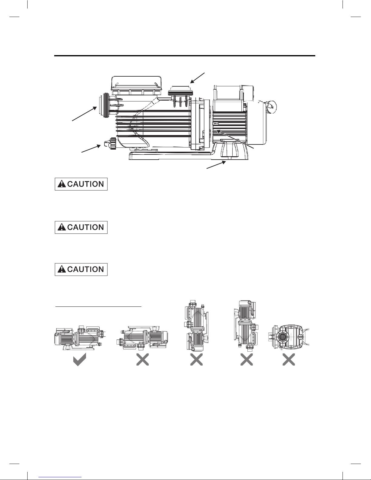
The fittings on these pool pumps are constructed of ABS. Some PVC jointing
compounds are incompatible with ABS possibly causing failure to the product.
Check compound suitability prior to use.
All glued fittings and pipe work should be allowed to dry to atmosphere for
24 hours before closing installation. Failure to do so could cause injury or
installation failure.
Barrel Unions are to be hand tightened ONLY, to prevent damage occurring from
over-tightening.
Pump Mounting should be:
1) Pump position must be: Solid - Level - Rigid -Vibration Free. Pump should be
fixed to its support using bolts through the slots on the pump base.
2) Allow pump suction inlet height to be as close to water level as possible.
3) Allow for use of a piece of short, straight suction pipe into the suction port of the
pump (minimum length for 40mm diameter suction = 160mm; 50mm diameter
suction = 200mm) in order to minimise water turbulence entering the pump.
Installation
Pump Discharge/Outlet
Pump Discharge/Outlet
Equipotential bonding terminal
Mounting holes
Drain plug
Page 7
6
Installation
Operation
4) Allow for control valves in suction and discharge piping. (Essential if pump is
mounted below water level).
5) Have adequate floor drainage to prevent pump being immersed in water
due to flooding.
6) Protect from excess moisture, vermin, dust and weather.
7) Allow access for servicing pump and piping.
8) To provide adequate ventilation keep rear of motor clear (100mm Min)
9) Do not use electrical extension cords/leads.
10) Do not connect pump to the mains water supply.
This appliance is not intended for use by persons (including children)
with reduced physical, sensory or mental capabilities, or lack of
experience and knowledge, unless they have been given supervision
or instruction concerning use of the appliance by a person
responsible for their safety.
Children should be supervised to ensure they do not play with the
appliance.
NEVER run pump dry! Running pump dry may damage seals,
causing leakage and flooding! Fill pump with water before
starting motor.
240 volt single phase are supplied as standard with built in thermal
overload protection and are designed to plug direct into a 10 amp
domestic power supply socket to local electrical authority
specifications. The pump is to be supplied by an isolating transformer
or supplied through a residual current device (RCD) having a rated
residual operating current not exceeding 30 mA.
Pump suction is hazardous and can trap and drown or disembowel
bathers. Do not use or operate swimming pools, spas, or hot tubs if
a suction outlet cover is missing, broken, or loose.
Entrapment Protection
Suction Outlet Covers
Testing and Certification
Electrical Operation
Follow the
guidelines below for a pump installation which minimises risk to users of
pools, spas and hot tubs.
The pump suction system must provide protection against the hazard of
suction entrapment or hair entrapment/entanglement.
All suction outlet covers must be maintained. They must be replaced if
cracked, broken, or missing. See below for outlet cover certification
requirements. All suction outlets must have correctly installed, screwfastened covers in place.
Suction outlet covers must have been tested by a nationally recognised
testing laboratory and found to comply with the latest AS1926.3-2010
Standard or ASME/ANSI Specification for
Suction Fittings For Use in
Swimming Pools, Spas, Hot Tubs, and Whirlpool Bathtub Applications.
The Pantera series of pool pumps is classified as "Double Insulated to Water Circuit". Please refer to the
Electical Wiring Rules (AS/NZS 3000) and local statutes and regulations as to whether equipotential bonding is
necessary. Pentair Water Australia recommends equipotential bonding for additional safety.
Page 8

7
Operation
Priming Pump:
a) In a flooded suction system (water source higher than pump), the pump will fill
itself with water when suction and discharge valves are opened. Water will be at
the top of the hair and lint pot lid.
b) If pump is not in a flooded suction system, unscrew and remove hair and lint pot
lid; fill pot (casing & bowl assembly) with water.
c) Clean, inspect and lubricate ‘O’ring; reinstall ‘O’ring onto bowl assembly.
d) Replace lid onto bowl assembly; turn clockwise to tighten lid.
Tighten lid by hand only (no wrenches)!
Do not run pump dry or damage will occur and
may void warranty.
Start-up Procedure:
1) Release all air from filter and piping system: see filter owner’s manual.
2) Turn pump “ON” at power point or controller.
3) Pump should prime now. Priming time will depend on vertical length of suction lift
and horizontal length of suction piping.
If pump does not prime within a few minutes, make sure that all valves are open,
suction pipe end is under water and that there are no leaks in suction pipe. Ensure
the skimmer basket on pool is clean and free of debris. Repeat step a) - d) under
the section Priming Pump. If the pump still does not prime non return valves may
be required refer to place of purchase for assistance.
Page 9

If water is seen to be leaking from directly underneath motor
and casing, have pump serviced immediately.
This indicates a leaking mechanical seal. Failure to fix this may result in
premature product failure.
NOTE: Onga recommend the use of silicon based lubricant on all ‘O’rings.
The only routine maintenance needed is inspection/cleaning of leaf basket. Debris
or trash that collects in basket will choke off water flow through the pump. Follow
instructions below to clean leaf basket and inspection for signs of a leaking
1. , disconnect from power, close gate valve in suction and discharge.Stop pump
2. Unscrew lid (turn counter clockwise). If necessary, undo drain plug to reduce lid
vacuum. Do not hit the lid with a hammer or similar tool. If the lid is still too tight use
a lever such as a board or long screwdriver between lugs on lid.
3. Remove leaf basket and clean. Be sure all holes in basket are clear, flush basket
with water and replace in bowl assembly with large opening at pipe connection port
(between ribs provided). If basket is replaced backwards the lid will not fit into bowl
assembly.
4. Inspect, check and lubricate lid ‘O’ring; reinstall onto bowl assembly.
5. Clean ‘O’ring groove on bowl assembly and replace lid. To help keep lid from
sticking,( tighten hand tight only no wrenches!).
6. Prime Pump (see priming instructions)
NOTE : Failure to carry out routine maintenance may reduce pump performance
and void warranty.
Service & Maintenance
8
mechanical seal:
NOTE : If the supply cord is damaged, it must be replaced by the manufacturer,
its service agent or similarly qualified persons in order to avoid a hazard.
Page 10

9
Switch off power and remove plug from power point. If the pump is hard wired
into any other controls such as time clocks or automatic heads etc., THE WIRING
SHOULD BE REMOVED BY A QUALIFIED ELECTRICIAN.
Close control valves and undo barrel unions from suction and discharge lines.
Remove pump and take to your nearest authorised Onga service agent
If the need arises to contact an Onga service agent please have all details
available including model and serial number, date of purchase and
particulars of fault.
If service parts are required please quote Model Number and Type of pump as
shown on the label of the pump.
Removal of Pump for Servicing
PPP-550-1P PPP-750-1P PPP-1100-1P PPP-1500-1P
(405976) (405976) (405977) (405977)
801210 801210 801277 801277
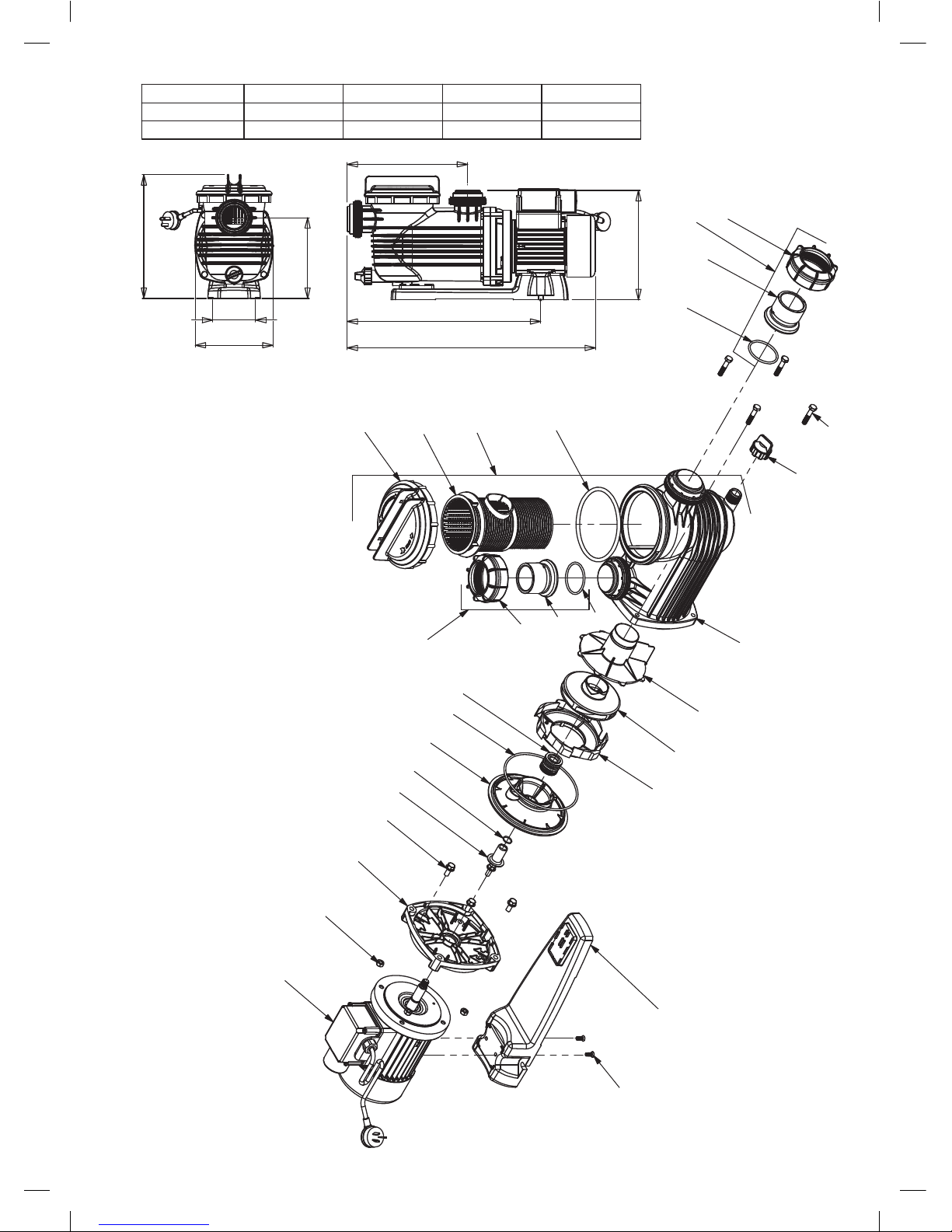
2 BASE 1
3 SCREW M6 x 16mm C/SNK HD Phlps 2
BASE & SCREW KIT (INCLUDES 2&3) 1
800532 800532 800532 800532
4 NUT 5/16inW 4
5 SHAFT SLEEVE 1
6 ORING SHAFT SLEEVE 1
7 YOKE AND LIP SEAL 1
8 SCREW 5/16inW x 3/4in 4
YOKE KIT (INCLUDES 7&8) 1
412050K 412050K 412050K 412050K
9 BAFFLE 1 305300 305300 305300 305300
10 ORING CASING 1
11 MECHANICAL SEAL 1
SEAL KIT (INCLUDES 5,6,10&11) 1
800583K 800583K 800583K 800583K
MECHANICAL SEAL (PACK OF 25) 25 800900 800900 800900 800900
12 DIFFUSER 1 305460 305460 303460K 303460K
13 IMPELLER 1 512750K 507530K 506840K 506820K
14 SEPERATOR PLATE 1 408730 408730 408730 408730
15 CASING ASSEMBLY (INCLUDES 16,17,18&19) 1 801200 801200 801200 801200
16 CASING 1
17 BASKET 1 302310 302310 302310 302310
18 LID 1
19 O-RING LID 1
LID AND O-RING KIT (INCLUDES 18&19) 1 800897K 800897K 800897K 800897K
20 BARREL UNION KIT (INCLUDES 21,22&23 X2) 1 800714 800714 800714 800714
21 TAIL BARREL UNION WHITE 2
22 NUT BARREL UNION WHITE 2
23 O-RING BARREL UNION 2
24 DRAIN PLUG 1
504605 504605 504605 504605
25 BOLT 5/16inW x 1.3/4in 4
FASTENERS KIT (INCLUDES 4&25 X4) 1
801278 801278 801278 801278
See Base and Screw Kit
See Lid & O-Ring Kit
See Casing Assembly
No.
MOTOR11
See Fasteners Kit
See Yoke Kit
See Seal Kit
Description Qty
See Barrel Union Kit
See Fasteners Kit
See Seal Kit
Part Number
Page 11
10
3
4
5
11
13
12
14
16
21
22
2
15
18
17
22
21
19
23
23
10
7
24
9
1
6
20
20
8
25
(MEASUREMENT WITHOUT BARREL UNION)
B
275
A
248
180
183
97
280
PPP550 PPP750 PPP1100 1500
A 565 565 602 602
B 428 428 465 465
Page 12

11
Trouble Shooting Guide
SYMPTOM CAUSE REMEDY
Pump does not Run No Power at the power outlet Use another electrical appliance
that is known to work to check the
power point.
Blown Fuse. Check Fuse and replace if
necessary
Automatic Thermal Overload has
tripped to protect the motor.
Switch the power to the pump off
and allow the motor to cool before
switching back on.
Ensure that the pump and motor
have adequate ventilation in the
area surrounding the pump.
Ensure that the pump is not
jammed with debris and that the
motor shaft spins freely
The motor may be operating on a
low voltage supply.
Pump is jammed (check if shaft
is free to rotate,
Blockage in the pump or suction
strainer.
Motor bearings may be seized.
Motor burnt out due to voltage
spike or flooded by water
The motor may need replacing.
Valves turned to the closed
position
Check the plumbing to ensure
the valves are in the correct position
for filtering, including any valves
on the suction or discharge of the
pump.
Dirty Filter Clean the filter (refer to the
documentation supplied with your
filter).
Air ingress to system Re-prime the pump (refer to prim-
ing procedure).
Check that there are no air leaks in
the suction piping or fittings.
Ensure the hair & lint pot lid
is closed and airtight.
Check there are no leaks coming
from beneath the pump and casing.
by inserting a
screw driver into the slot in the
centre of the motor fan and turning)
(insert a
screw driver into the slot in the
centre of the motor fan and turn).
Pump operates with reduced or
no flow
Page 13

12
Trouble Shooting Guide
SYMPTOM CAUSE REMEDY
Lack of water Ensure the water level in your pool
is at least up to the halfway mark at
the skimmer opening.
Debris in the pump or skimmer
box
Note: Do not operate pump without hair & lint pot or skimmer
basket fitted correctly
Ensure that both the hair & lint pot
basket and skimmer basket are
free of leaves and other debris.
Ensure that there is no blockage at
the pumps suction or discharge.
Ensure that the pump internals
are free of foreign matter which may
block the flow of water.
Pump leaking from between the
casing and the motor
Casing bolts are not tightened
Casing ‘O’ring is worn
Mechanical Seal needs replacing
Switch off pump and loosen the
casing bolts. Check alignment and
condition of casing ‘O’ring before
re-tightening. Replace the ‘O’ring if
leaking persists.
Replace the mechanical seal and
lip seal if fitted.
-Should problems persist please contact your nearest Onga service agent.
Page 14

Notes:
Page 15

Notes:
Page 16

IMPORTANT
Please attach your sales invoice/docket here as proof of purchase should
warranty service be required.
Please do not return Warranty Form to Pentair Australia please retain for your records.
Purchased From ...................................................................................................................
Purchase Date..................................... Serial No.............................. Model No........................
© Information contained here-in remains the property of Pentair Water Pty Ltd. Any reproduction,
display, publication, modification or distribution is strictly prohibited without the prior written
permission of Pentair Water Pty Ltd.
Disclaimer: Every endeavour has been made to publish the correct details in this data sheet.
No responsibility will be taken for errors, omissions or changes in product specifications.
Pentair Water reserves the right to change specifications
Head Office
Pentair AU/NZ: 1-21 Monash Drive,
Dandenong South, Vic 3175
Australia
National Customer Service: Phone: 1300 137 344
Fax: 1800 006 688
National Dealer Locator: Phone: 1800 664 266
New Zealand
National Customer Service: Phone: 0800 654 112
Fax: 0800 806 642
National Dealer Locator: Phone: 0800 664 269
International Australia/New Zealand
Phone: +61 3 9709 5800
Fax: +61 3 9709 5888
L100187 0912
 Loading...