

Page 1
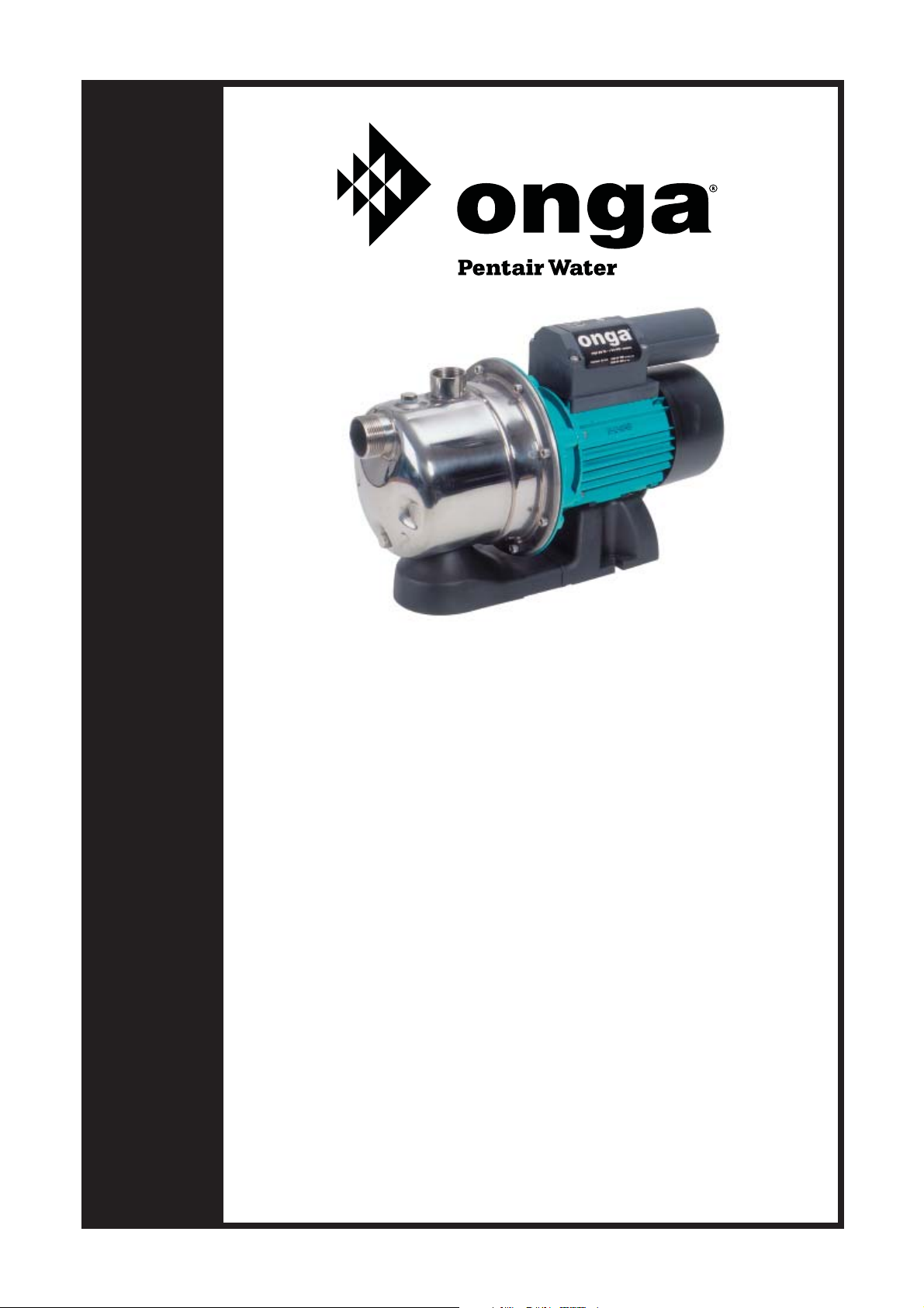
OWNER’S MANUAL
Jet Assisted Pumps
1000 Series
JMM100 JS100 JSM100 JSK110
JS110 JSP110 JSK120
JS120 JSP120
We recommend, for additional protection, the pump
to be supplied from socket outlet protected by a
Residual Current Device – RCD (also known as
an Earth Leakage Circuit Breaker – ELCB) with a
maximum rated residual current of 30mA.
Should you the installer or owner be unfamiliar with the correct
installation or operation of this type of equipment you should contact
the distributor for the correct advice before proceeding with the
installation or operation of this product.
Page 2
Relax - you’ve bought an ...
Congratulations on your decision to purchase an Onga product.
Onga is one of the best know brands in its fi eld, with a proud local
and international reputation.
Onga is a brand for reliability, value for money and technological
innovation. You will fi nd Onga product wherever people need to
move water in 3 broad markets covering:
Technologically advanced solutions for
moving and treating water in the Home,
Garden, Pool and Spa.
Innovative Stock and Crop water
management solutions for Primary
Industries.
Water movement products for Building
services, Emergency services and
Original Equipment Manufacturers.
1
Page 3

1. Continual Product Improvement
We employ the best engineers both in Australia and
around the world to develop new and better ways to
take water further.
2. Operational Excellence
There is only one standard that we set ourselves for both
product quality and the quality of our service. That standard
is excellence... to have no-one better than us at what we
do... nothing short of that is acceptable. Our commitment to
quality is reinforced with our ISO 9001:2000 accreditation.
3. A Fair Price
Onga products are neither the cheapest nor the most
expensive in their fi eld. Our products do, on the other hand,
always represent very good value for money; they always
have and they always will.
4. Our Team of Dealers
The hand picked authorised Onga dealer network throughout
Australia and worldwide are second to none. We invest
considerable time and resources training and supporting
them through the Onga Training Academy.
2
Page 4

Table of Contents Page
Model Data 4
Application 5
Installation 6
Operation 11
Service and Maintenance 13
Troubleshooting 14
Warranty 17
3
Page 5
Model Data
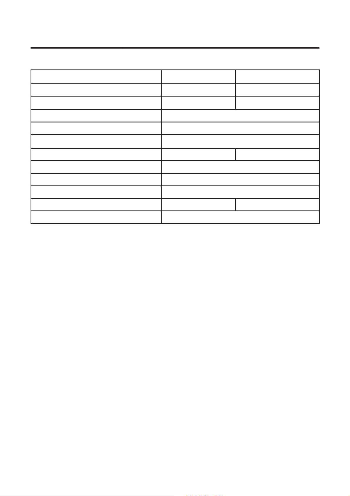
Technical Information JM JS
Inlet Connection 1”BSP Male 1”BSP Female
Outlet Connection 1”BSP Male 1”BSP Female
Power Supply 230V
Voltage Limits (+/- 10%) 207-253V
Impeller (s) Technopolymer
Pump Case Polypropylene Stainless Steel
Pump Shaft Stainless Steel
Mechanical Seal Carbon/Ceramic
Motor TEFC IP44
o
Maximum Water Temp (
C) 40 50
Ambient Temp Range (
o
C) 1-50
4
Page 6

Application
Onga 1000 Series pumps are suitable for pumping clean water in a
domestic water system, small irrigation applications, and general water
transfer. The Onga 1000 Series Jet-Asssisted pumps are fantastic at selfpriming, easy to install, and come in a wide range of packages to suit
almost any application.
5
Page 7
Installation
The electrical installation shall be in accordance with the national
wiring rules (AS/NZS 3000) for class 1, IP44 rated products.
These instructions are a guide only. Users not familiar with
pumping equipment should seek advice from people experienced
in pump equipment and installation.
Freezing conditions will damage the unit, because when water
freezes it expands. Ensure that the pump is located so that it is
not prone to freezing, or ensure that the product is disconnected
and dried of water during cold conditions.
The pump is electrically connected. Ensure that it is isolated
from electrical supply during installation and any subsequent
service work.
The pump is designed to be used with clean water in a residential
application. Do not use it with alternative fl uids, abrasive,
corrosive or explosive fl uids. Do not install or operate your pump
in an explosive environment or near combustible matter.
Incorrectly installed or tested equipment may fail, causing severe
injury or property damage.
Fire and burn hazard. Modern motors run at high temperatures.
To reduce risk of fi re, do not allow leaves, debris, or foreign
matter to collect around the pump motor. To avoid burns when
handling the motor, let it cool for at least 20 minutes before trying
to work on it. A thermal overload switch protects the motor for
heat damage during operation.
Read the following instructions in this owner’s manual when installing and
operating equipment.
6
Page 8

1. Preparation for Installation
Inspect your pump for shipping damage. Report any damage to your Onga
Dealer. Make sure the suction piping is free of air leaks and is laid so that
there can be no airlocks.
Warranty of these pumps is void unless they are operated in accordance with
this owner’s manual.
2. Pump Protection
The pump should be protected from the weather, fl oods, chemicals, dust,
vermin, insects etc. It is highly recommended that the pump be housed in a
weather proof, well vented enclosure. If the pump is not adequately housed
the warranty may be deemed void.
Connection with a mains Pressure Hot Water System
The maximum pump pressure specification is 600kPa. It
is important that a reliable pressure relief valve (set to the
maximimum specifi cation or lower) is installed between the pump
control discharge and the mains pressure Hot Water Service.
Failure to install this device may lead to product damage not
IMPORTANT
covered by the manufacturers warranty.
3. Pipe Installation
Pumps can be damaged if care is not taken when connecting pipes. Pipes
should be supported so that the pump casing is not strained by the weight
or misalignment.
We recommend the pump and pipe are coupled using fl exible type polythene
pipe, rubber hose or a multi-directional barrel union. This union coupling can
also be used to remove the pump for service should it be necessary without
having to cut pipes.
Pipe fi ttings should be carefully screwed onto the pump making sure not to
cross-thread or overtighten. We recommend the use of a moulded pipe fi tting
to connect to the pump as this avoids possible damage to the pump threads
and unnecessary replacement of parts.
For best results use tefl on tape to join seal joint. Satisfactory sealing can be
achieved by hand tightening fi ttings ensuring that no leaks are evident once
under pumping pressure.
4. Locating the Pump
Find a location for your pump as close to your water source as possible.
7
Page 9
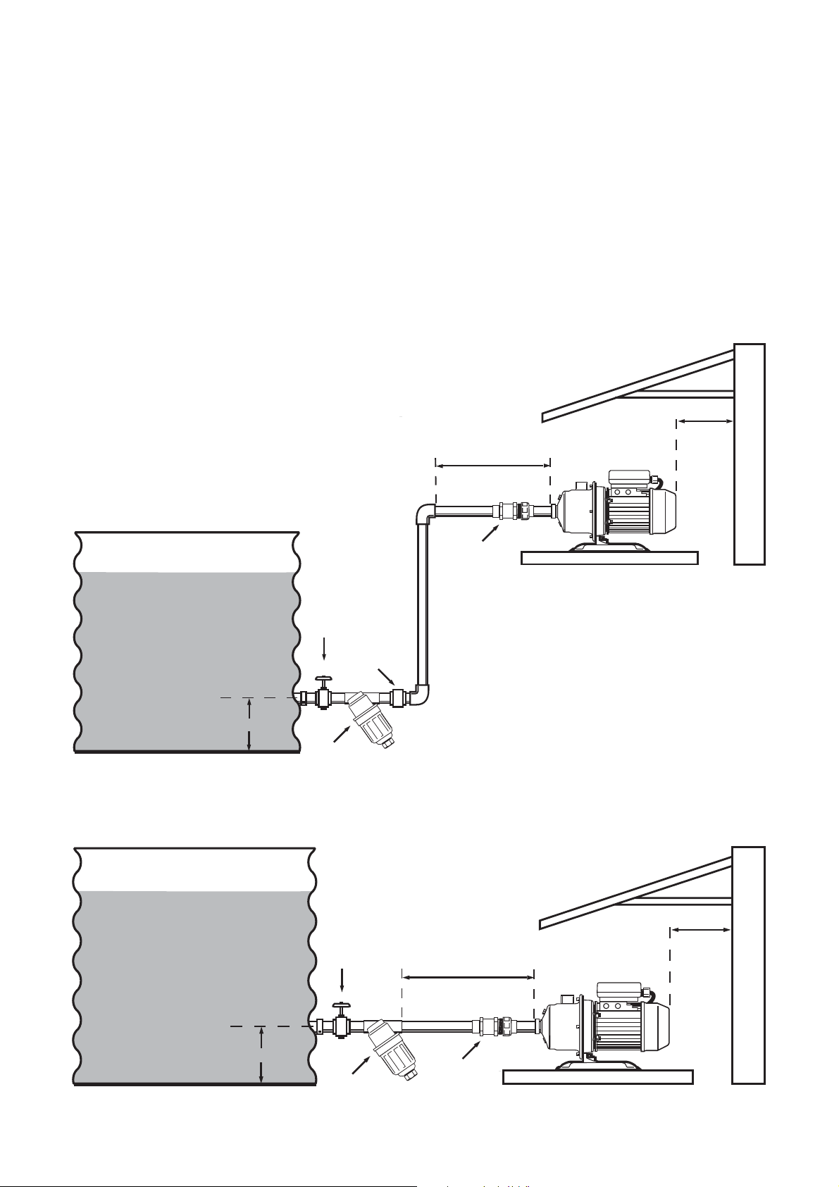
Ensure that this location is on a seperate footing from your home. To do this
you can mount the pump on a concrete tile or concrete base.
5. Power Source
Arrange for an electrician to install an outdoor 10A GPO electrical outlet near
the pump if there is not one there already.
6. Suction
This is the most important part of the installation as errors will cause signifi cant
problems for the system in performance and longevity.
IMPORTANT: A gate valve must be installed at the tank outlets.
Installations where the tank base is below the pump
Min 100mm
Recommended Length 150mm
Barrel Union
Solid Base
Gate
Valve
Non-Return
Valve
100mm
In Line Filter
500 Micron
Installations where the tank base is level with the pump
Gate
Valve
Recommended Length 150mm
House Wall
Min 100mm
100mm
In Line Filter
500 Micron
Barrel Union
8
House Wall
Solid Base
Page 10

To maintain optimum performance from your pump, the suction pipe should
be:
- Kept to the shortest distance practical, but not shorter than
the recommended length.
- Re-enforced crush resistant (non-collapsable) hose or pipe.
- All fi ttings should be air tight.
- Pipes should be equal to or larger than the diameter of the
suction/inlet port.
- Optional: Fitted with a suction Strainer/Filter
In-line strainers/fi lters are only recommended for pumps fi tted with Minipress
or PressControl. Regular maintenance is required to keep them clean and
provide maximum pump pressure.
7. Discharge
The length and diameter of the discharge hoses/pipes will affect the pressure
and fl ow rate at which your pump operates. Pressure ratings of all components
must exceed the maximum pressure of the pump by an appropriate safety
factor. All pipework should be supported independently of the pump.
Connect the fi tting at the top of the pressure controller (1”BSP Male) to the
household plumbing or garden taps*.
*If you want to test that the pump is operating correctly prior to having the plumbing connected,
attach a hose with a trigger nozzle to the top of the pressure controller.
8. Pump Priming
Ensure that there is at least 200mm of water in your tank, (i.e. that the tank
outlet is covered, and the pump will not draw any air into the system). Open the
gate valve on the tank. Check for any leaks, and repair these if necessary.
If no leaks are present, remove the priming plug to open the priming port on
the top of the pump case.
If the tank is above the level of the pump, water will start to run out of this
port. Replace the priming plug carefully. Your pump is now ready to run.
(Note: If a check valve is installed in the suction line, water may not fi ll the
pump. If this occurs, follow the instructions below).
If the tank water level is below the level of the pump, you will need to fi ll the
pump body and suction line. Remove the priming plug and fi ll the pump body
and suction line using a funnel.
9
Page 11
9. Electical Installation
The pump is supplied with a interconnection appliance coupler and standard
Australian 10 Ampere plug and cord. Connection to the power supply is a
matter of inserting the plug into the suitable socket outlet. Before plugging
the power supply cord into the socket outlet, connect the pump to it using the
provided IEC appliance connectors on the end of the interconnection cords.
Ensuring there are no water traces on the connectors push them fi rmly into
each other to ensure intended splash (water) proof protection. This connection
shall be separated again only for service purpose and only after the power
supply is removed by unplugging the cord from the socket outlet.
The socket outlet shall be in a dry and fl ood free location; preferably do not
use extension cords for this very reason and because they can cause voltage
drop.
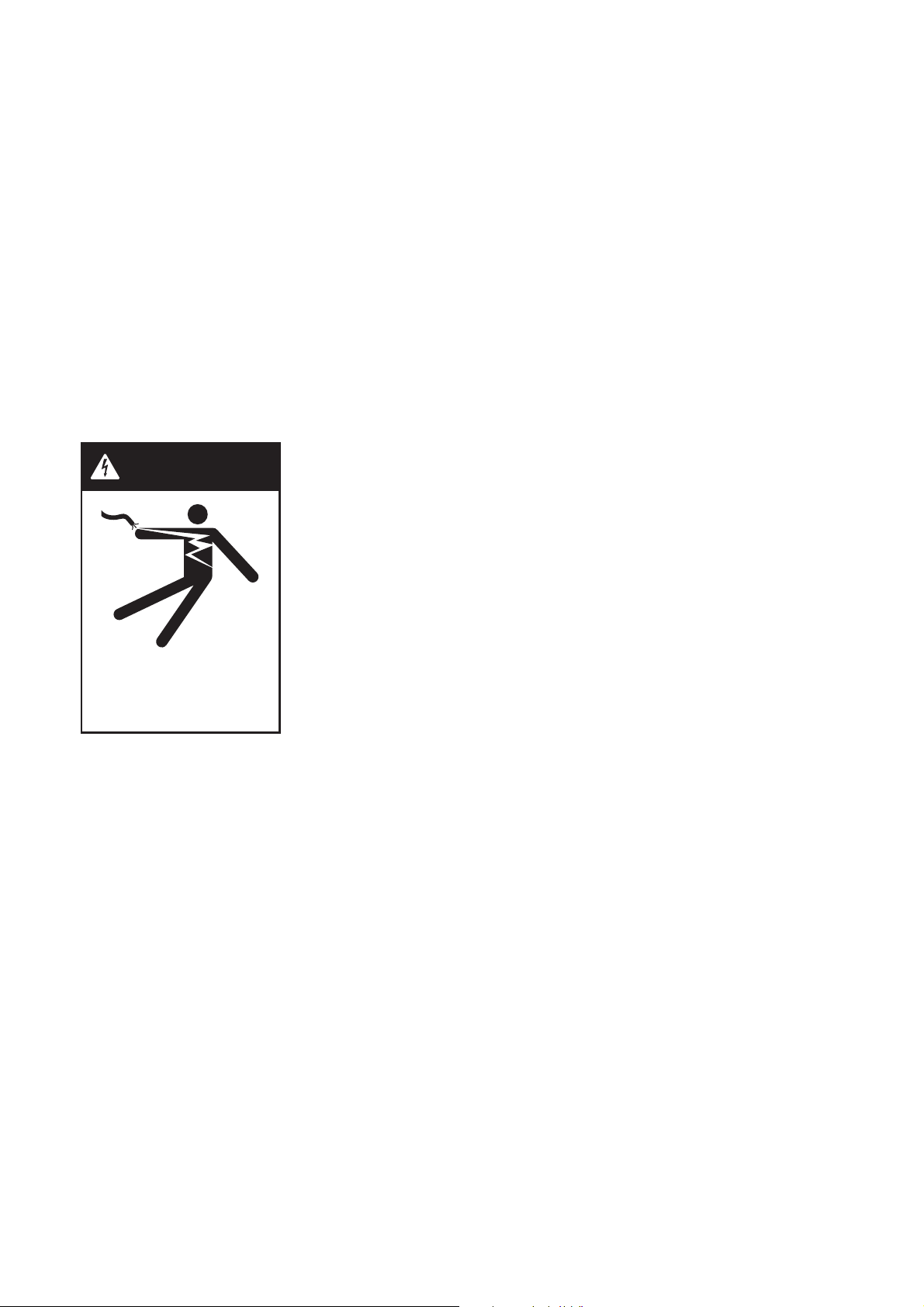
Supply voltage outside limits specifi ed in Model
WARNING
Data can cause motor overheat leading to overload
tripping, reduced component life or seriously
damage pump and voids warranty.
Hazardous voltage.
Can shock, burn, or
cause death.
We recommend, for additional protection, the
pump to be supplied from socket outlet protected
by a residual current device – RCD (also known as
an Earth Leakage Circuit breaker – ELCB) with a
maximum rated residual current of 30mA.
10
Page 12
Operation
The pump operator or owner must be provided with this owner’s
manual. This must be read before operation, and followed during
operation.
Ensure that your pump is fi lled with water before operating.
The pump is designed to be used with clean water in a residential
application. Do not use it with alternative fl uids, specifi cally
abrasive, corrosive or explosive fl uids. Do not install or operate
your pump in an explosive enviroment or near combustible
matter.
Fire and burn hazard. Modern motors run at high temperatures.
To reduce risk of fi re, do not allow leaves, debris, or foreign
matter to collect around the pump motor. To avoid burns when
handling the motor, let it cool for at least 20 minutes before trying
to work on it. A thermal overload switch protects the motor for
heat damage during operation.
DO NOT RUN PUMP DRY
Ensure that your pump is fi lled with water before operating
1. Start-up / Operation
Priming
Prime the pump through the top priming plug port or outlet so that the pump
and suction line are full. Discharge pipework attached, turn pump on and
allow to operate until primed and all air is fl ushed out of suction and discharge
lines.
JMM, JSM & JSP Models only
When the power is turned on, the pump will start, and stop as soon as it has
pressurised the system it is connected to. If the pump does not start, press
11
Page 13

the ‘restart’ button on the front of the pressure controller. Open a tap, (or
garden hose nozzle) and the pump should start and deliver water. When the
tap is closed, the pump will stop once pressure is built up in the system. The
system is now working correctly.
If no water is delivered, check the troubleshooting section on Page 14 of
this manual, and additionally, refer to the pressure controller installation and
operating instructions packaged with the controller.
JSK Models only
2. Pressure Switch
The Pressure Switch should be screwed onto the 3/4” port on the 5 way tee.
No sealing tape should be necessary and the locknut should only be just
over handtight to seal.
All pressure switches are factory set and will suit most domestic requirements
but may require further adjustment accordingly to individual installations.
3. Aqua Packs
Aqua Packs must be charged with air before installation. The air pressure used
should be 10% lower than the pressure switch cut-in setting of the pump, (e.g.
a pump working on 20-40 psi should have a tank air charge of 18 psi.)
Aqua Packs should be installed under cover, out of the weather, and the air
pressure should be regularly maintained.
4. Aqua Pack Tank Recharge Procedure
The air charge should be checked at least once a year as tanks gradually lose
air which causes pump cycling and pressure switch setting problems.
To check air pressure, turn off the electricity to the pump. Turn off the gate
valve from the water supply. Turn on a tap so that the water is drained from the
pump. Only then, measure the air pressure in the tank using a tyre pressure
gauge on the valve. If the pressure is low, recharge using a tyre pump. Do not
over charge the tank with air as this will cause tank liner damage, pressure
surge problems and/or the system to malfunction.
False readings can be obtained when checking the air pressure unless the
pressure tank is completely empty of water. If in doubt, turn off water supply,
drain discharge line and then disconnect the tank from the pipe work. When
the air pressure is correct, re-install the tank, open gate valve from the supply
tank and turn on the electricity. The pump should now operate normally once
any air is purged from the lines.
12
Page 14
Service and Maintenance
Pump should only be serviced by qualifi ed personel. For best
results, use only genuine service parts. Be sure to prime pump
before starting.
To avoid dangerous or fatal electrical shock hazard, turn OFF
power to motor and remove plug from power outlet before
working on pump or motor.
Liquid may be HOT, release pressure with care before
servicing.
1. General Care and Maintenance
No lubrication or regular maintenance is needed beyond reasonable care.
When pump is not in use for a long period of time, empty the pump, rinse it
with clean water and place it in dry storage.
In order to prevent possible failures, it is advisable to periodically check the
pressure supplied and power absorption. A decrease in pressure is a symptom
of wear. An increase current absorption is a sign of abnormal mechanical
function in the pump and/or motor.
13
Page 15
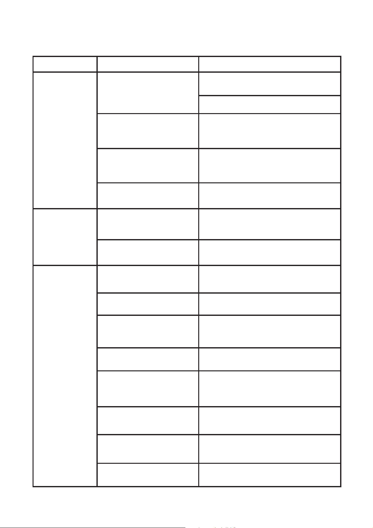
Troubleshooting
Symptom Cause Remedy
Pump does not
Start
Pump will not
stop, even
though there is
no taps open.
No Electricity
Pressure Controller has
detected that there is not
water in tank.
Pump is blocked Disconnect the pump from the power
Defective Capacitor Call qualifed service technician
Debris is caught in the
pressure controller
There are leaks in the
household plumbing
Ensure that the pump is connected to a
live outlet.
Check Circuit breakers and Fuses
Check that there is enough water in the
tank, then press the “reset” or “Start”
button on the pressure controller.
outlet, and check the pump housing and
discharge for foreign matter.
Take the pressure controller to your
Onga dealer for service.
Find and fi x leaks
No Water From
Pump
Pump is not primed Ensure that pump body and suction line
are fi lled with water before starting.
Suction line is leaking Check the suction line for leaks
especially at joints.
Blockages in the pump or
discharge
Valves Closed Check all valves on the tank, pump, and
Not enough water in the
tank to pump.
Pump does not produce
enough pressure
Pressure Switch is out of
adjustment
Disconnect the pump from the power
outlet, and check the pump housing and
discharge for foreign matter
outlets.
Wait until there is more water in the tank.
Press the ‘reset’ or ‘start’ button on the
pressure controller.
Check and clean pump
Check system pressure and adjust
accordingly
In-Line fi lters or tap fi lters
are blocked
14
Clean fi lters
Page 16
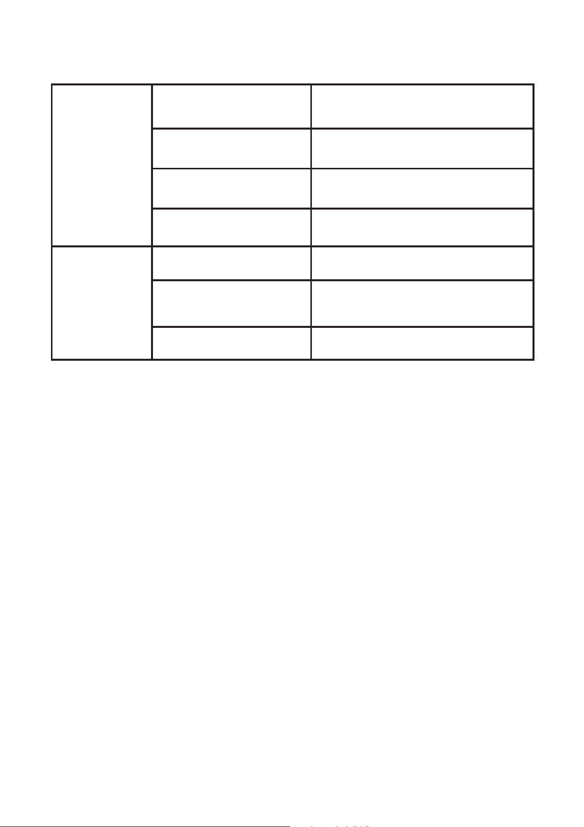
Pump Runs
Intermittently
There are small leaks in the
household plumbing
Find and fi x leaks
Poor
Performance
- low pressure
or fl ow.
Water Temperature is too
high
Voltage is outside allowable
limits (see specifi cations)
Not enough air fl ow to cool
motor
Suction line is leaking Check the suction line for leaks,
Tank water level is too far
below the pump.
Pump is worn or damaged Ask your Onga dealer to investigate
Ensure the water temperature limits are
observed
Check voltage level being delivered, and
correct where necessary
Provide adequate ventilation to motor
cooling fan
especially at joints
Talk to your Onga dealer about a better
pump for your situation, or move the
pump closer to tank.
worn parts.
Should problems persist, contact your nearest Onga Service Agent.
15
Page 17

Notes
16
Page 18

Pentair Water Product Warranty
Pentair Water warrants that, when this product is used for the purpose it was designed, is correctly housed and vented against
weather, vermin, dust etc., that it will be free of material and manufacturing defects at the time of the original purchase.
This warranty is limited to the cost of the product and does not cover third party costs including the costs of
electricians, plumbers, etc. unless authorised by Pentair Water.
TERMS AND CONDITIONS APPLICABLE INTERNA TIONALLY
How long the warranty is effective Internationally
1) This Pentair Water product is warranted for 12 months for all parts from the date of the fi rst consumer purchase. Should
any parts fail as a result of such defects within the specifi ed period, the part will be replaced free of charge. (This does
not include travel charges, removal and reinstallation charges.)
TERMS AND CONDITIONS APPLICABLE IN AUSTRALIA AND
NEW ZEALAND
1) YOU SHOULD CAREFULLY READ THE INSTRUCTIONS SUPPLIED PRIOR TO USING THIS PENTAIR
WATER PRODUCT.
This product is to be installed and operated in accordance with the instructions
provided. This warranty will not apply if it is used in a manner other than in
accordance with the instructions.
What the warranty covers:
Pentair Water warrants its products to be free of defects in material and workmanship during the warranty period.
If a product proves to be defective in material or workmanship during the warranty period, then Pentair Water
will, at its sole option repair or replace the product with a like product. Replacement product or parts may include re-
manufactured or refurbished parts or components.
How long the warranty is effective:
1) This Pentair Water product is warranted for 24 months for all parts from the date of the fi rst
consumer purchase.
2) Authorised workshop labour will be free of charge for the fi rst 12 month period from date of the fi rst
consumer purchase when unit is found to have failed due to defective workmanship or material
supplied by Pentair Water Australia.
Infi eld service by an authorised Pentair Water Service Agent will incur a travel, removal &
reinstallation fee payable by customer.
3) Where this Pentair Water product is sold for commercial application as defi ned in the relevant Trade
Practices and Consumer Protection legislation the warranty shall be for a period of six months from
the date of purchase by the end user.
Who the warranty protects:
This warranty is valid only for the consumer purchaser.
What the warranty does not cover:
1) Damage, deterioration or malfunction resulting from:
a) accident, misuse, negligence, fi re, water, lightning, or other acts of nature, unauthorised product
modifi cation or failure to follow instructions supplied with the product;
b) repair or attempted repair by anyone not authorised by Pentair Water;
c) any damage to the product due to shipment;
d) removal or installation of the product;
e) causes external to the product such as electric power fl uctuations or failure;
f) use of supplies or parts not meeting Pentair Water specifi cations;
g) normal wear and tear;
17
Page 19

Pentair Water Product Warranty (Continued)
h) water ingression or exposure to abnormal corrosive conditions or “run dry” conditions;
i) any other cause which does not relate to a product defect.
2) Damage caused to the product as a consequence of use of another manufacturer’s product used in
conjunction with Pentair Water and affi liate companies.
3) Ingress of insects into the unit causing electrical malfunction is not warranted, care should be taken
to avoid this occurrence.
Spare Parts:
Spare parts are usually stocked for a reasonable period of time following last production.
Pentair Water does not warrant that spare parts will be made available for the whole of the reasonable
period and reserves its right to cease supplying spare parts or providing facilities for repair of spare parts
in circumstances which are beyond its control including the requirement to remove spare parts from sale
as a consequence of changes in the law or otherwise as it deems fi t.
How to get service:
In Australia please contact 1800 664 266 In New Zealand please contact 0800 664 269
Claims under this warranty must give evidence of date of purchase, model and serial number of the
product and the claimants name, address and telephone number.
1) To obtain warranted service, you will be required to provide to either Pentair Water state offi ce or
recommended service agent:-
a) the product;
b) confi rmation in writing specifying the nature of your claim;
c) proof providing date of original purchase;
d) full contact details including name and address;
e) the serial number of the product if any.
2) The product is to be forwarded by the customer freight paid to an Authorised Pentair Water service
agent.
3) Warranty service work will be denied or suspended, on equipment not readily accessible to service
personnel, that is products that are behind barriers, tiled or bricked in, installed in roofs or second
story external walls including inaccessible power points.
4) Any service of any product which is found to be faulty due to abuse, fair wear & tear, misuse or improper
installation will be charged to the owner at the service agents current servicing hourly rate.
Limitation of implied warranties:
THERE ARE NO WARRANTIES, EXPRESSED OR IMPLIED, WHICH EXTEND BEYOND THE DESCRIPTION
CONTAINED HEREIN INCLUDING THE IMPLIED WARRANTY OF MERCHANTABILITY AND FITNESS FOR A
PARTICULAR PURPOSE.
Exclusion of damages:
PENT AIR W ATER’S LIABILITY IS LIMITED TO THE COST OF REPAIR OR REPLACEMENT OF THE PRODUCT.
ONGA SHALL NOT BE LIABLE FOR:
1) DAMAGE TO OTHER PROPERTY CAUSED BY ANY DEFECTS IN THE PRODUCT, DAMAGES BASED
UPON INCONVENIENCE, LOSS OF USE OF THE PRODUCT , LOSS OF TIME, LOSS OF PROFITS, LOSS
OF BUSINESS OPPORTUNITY , LOSS OF GOODWILL, INTERFERENCE OF BUSINESS RELA TIONSHIPS,
OR OTHER COMMERCIAL LOSS, EVEN IF ADVISED OF THE POSSIBILITY OF SUCH DAMAGE.
2) ANY OTHER DAMAGES, WHETHER INCIDENTAL, CONSEQUENTIAL OR OTHERWISE.
3) ANY CLAIM AGAINST THE CUSTOMER BY ANY OTHER PARTY.
Effective law:
This warranty gives you specifi c legal rights, and you may also have other rights which vary from state
to state. Nothing in this warranty limits or restricts, or is intended to derogate from, any right or remedy
which the purchaser or ultimate user of the product may have pursuant to Australian state and/or Australian
federal consumer protection legislation, New Zealand Sale of Goods Act, Consumer Guarantees Act, Fair
Trading Act or any other relevant and applicable New Zealand legislation or authority and where necessary
shall so be read and construed.
18
Page 20
IMPORTANT
Please attach your sales invoice/docket here as proof of purchase should warranty service
be required.
Please do not return Warranty - Retain for your records.
Purchased From .............................................................................................. ........................
Purchase Date..................................... Serial No.............................. Model No........................
Pacific Head Office
Australia
Americas Pentair, Inc.
Europe Pentair Pumps S.p.A
Asia China
Pentair Water Australia Pty Ltd
Notting Hill Victoria, Australia
Tel: +61 3 9574 4000 Fax: +61 3 9562 7237
Email: [email protected]
www.pentairwater.com.au
Pentair Water New Zealand Ltd
Penrose Auckland New Zealand
Tel: +64 9 579 6254 Fax: +64 9 579 6497
Email: [email protected]
www.pentair.com
www.Pentairpumps.it
www.pentairwater.com
India
www.pentairwater.com
© information contained here-in remains the property of Pentair Water Pty Ltd. Any reproduction,
display, publication, modifi cation or distribution is strictly prohibited without the prior written
permission of Pentair Water Pty Ltd.
Disclaimer: Every endeavour has been made to publish the correct details in this owner’s manual.
No responsibility will be taken for errors, omissions or changes in product specifi cations. Pentair
Water reserves the right to change specifi cations
L100154 1106
 Loading...