

Onfloor Striker 2010 Owner's Manual

Operators Manual
STRIKER 2010
PN 236683 - Striker 2010 Parts List - Printed in USA 03/18/08


TABLE OF CONTENTS
PAGE
SAFETY PRECAUTIONS 2
OPERATION 3
OPERATOR RESPONSIBILITY 3
MACHINE COMPONENT LOCATIONS 4
CONTROL PANEL SYMBOLS 5
UNCRATING MACHINE 5
INSTALLING BATTERIES 6
ATTACHING SQUEEGEE 7
BRUSH PAD SELECTION 8
BRUSH PAD INSTALLATION 9
FILLING THE SOLUTION TANK 9
MACHINE OPERATION 10-11
DRAINING TANKS 11-12
CIRCUIT BREAKER FUSES 12
BATTERY METER 13
HOURMETER 13
CHARGING BATTERIES 13-14
14
MAINTENANCE
SQUEEGEE BLADE REPLACEMENT 15-16
SQUEEGEE ADJUSTMENT 16
BATTERY MAINTANENCE 17
TRANSPORTING MACHINE 17
STORING MACHINE 17
LED FAULT CODES 18
SPECIFICATIONS 18
GENERAL MACHINE DIMENSIONS 18
BATTERIES 18
SOLUTION DELIVERY SYSTEM 19
BRUSH SYSTEM 19
SOLUTION RECOVERY SYSTEM 19
DRIVE SYSTEM 19
SOUND RATING 19
1

SAFETY PRECAUTIONS
9
0-8
8
01
2
Open
Flam
e
s
Aw
ay
.
When
Ch
argi
n
g.
Keep Co
v
e
r
s Open
Explosi
on
Or
Fi
re
Hydrogen
Gas.
Batteries
Em
i
t
Keep S
parks
A
nd
WAR
NING
Can
Resul
t.
9
0-8
8
04
2
Material
s
I
n Tank(s).
WARNING
Ca
n Cau
se
E
xp
losi
on
Do
N
o
t
Use
Flammab
le
F
lamma
bl
e
Ma
t
e
rials
O
r
F
ire
.
WARNING
WARNING
90-88013
Do Not Pick Up
Explosions Or Fire
WARNING
Can Cause
Reactive Metals
Materials Or
Flammable
FOR SAFETY
Read Manual
Before Operating
Machine
90-88017
The safety labels appear on the machine in
the locations indicated. If these or any label
becomes damaged or illegible, install a new
label in its place.
FOR SAFETY
Read Manual
Before Operating
Machine
DECAL, PICKUP WARNING
DECAL, READ MANUAL
WARNING
Flammable
Materials Or
Reactive Metals
Can Cause
Explosions Or Fire
Do Not Pick Up
WARNING
OVERLAY SOLUTION WARNING
WARNING
Batteries Emit
Hydrogen Gas.
Explosion Or Fire
Can Result.
Keep Sparks And
Open Flames Away.
Keep Covers Open
When Charging.
Flammable Materials
Can Cause Explosion
Or Fire.
Do Not Use Flammable
Materials In Tank(s).
DECAL, CHARGING WARNING
2
OPERATOR RESPONSIBILITY
The operator’s responsibility is to take care
of the daily maintenance and inspection of
the machine to maintain it in optimal working
condition. It is the operators responsibility
to inform the service technician or supervisor
when the maintenance intervals are required
as stated in the MAINTENANCE section of
this manual.
Read this manual carefully before operating
this machine.
FOR SAFETY: Do not operate machine,
unless operation manual is read and
understood.
OPERATION
OPERATION
Inspect machine for shipping damage and
make sure the machine is complete according
to your order.
Keep your machine regularly maintained by
following the maintenance information in this
manual. We recommend a regularly scheduled
service contract with your authorized dealer.
Order parts and supplies directly from your
authorized dealer. Use the parts manual
provided when ordering parts.
After use, follow the recommended
daily and hourly procedures shown in the
MAINTENANCE CHART.
3
OPERATION
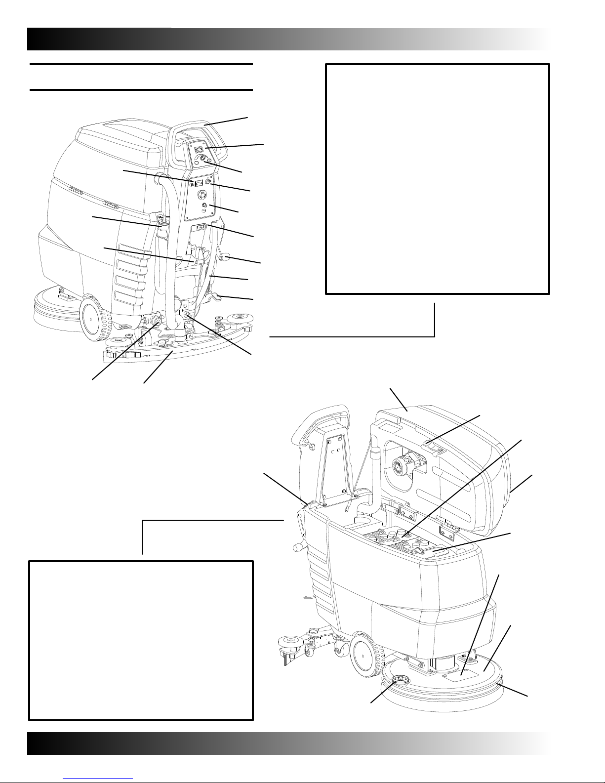
MACHINE COMPONENTS
/
.
-
#ONTROL(ANDLE
!
"ATTERY-ETER
"
6ARIABLE3PEED+NOB
!
"
#
$
%
&
'
(
#
-ACHINE0OWER+EY3WITCH
$
"RUSH-OTOR#IRCUIT"REAKER
%
"ATTERY#HARGING#ONNECTOR
&
"RUSH0RESSURE,EVER
'
3OLUTION4ANK3IGHT'UAGE$RAIN(OSE
(
3CRUB(EAD,IFT0EDAL
)
3OLUTION&LOW#ONTROL+NOB
*
3QUEEGEE!SSEMBLY
+
3OLUTION&ILTER
,
3QUEEGEE,IFT,EVER
-
2ECOVERY4ANK$RAIN(OSE
.
(OUR-ETER
/
)
*
,
0
2ECOVERY4ANK
1
"ATTERY#HARGING3UPPORT!RM
2
"ATTERIES
3
2ECOVERY4ANK#OVER
4
3OLUTION4ANK&AST&ILL0ORT
5
3CRUB"RUSH!CCESS/PENING
6
3CRUB$ECK
7
3CRUB$EBRIS3KIRT
8
%DGE2OLLER
9
(OSE&ILL/PENING
+
0
1
2
9
3
4
5
6
7
8
4

CONTROL PANEL SYMBOLS
4HESESYMBOLSIDENTIFYCONTROLSANDDISPLAYS
ONTHEMACHINE
OPERATION
INCREASE VEHICLE SPEED
DECREASE VEHICLE SPEED
SOLUTION FLOW
BATTERY CONDITION METER
VARIABLE FLOW OR RATE
NORMAL SCRUB PRESSURE
HEAVY SCRUB PRESSURE
BRUSH MOTOR CIRCIT BREAKER
UNCRATING MACHINE
1. Check shipping crate. If damaged, report
to carrier.
2. To uncrate machine, carefully remove
hardware and machine strapping.
ATTENTION: Do not roll machine off pallet
without a ramp.
ATTENTION: Install batteries after removing
machine from shipping pallet.
5
OPERATION
INSTALLING BATTERIES
WARNING: Fire OR Explosion Hazard.
Batteries Emit Hydrogen Gas. Keep Sparks
And Flames Away. Charge Batteries With
Cover Open.
FOR SAFETY: When servicing machine, wear
protective glove and eye protection when
managing batteries and battery cables. Avoid
contact with battery acid.
Battery Specifications:
Two deep cycle 12 Volt lead acid batteries.
155 AH battery - Recommended For 20”
Traction Scrubber.
105 AH battery 130 AH battery -
Maximum battery dimensions:
380 mm (15 in) Length
174 mm (6.85 in) Wide
284 mm (11.18 in) Height
1. Park machine on level surface and
remove key.
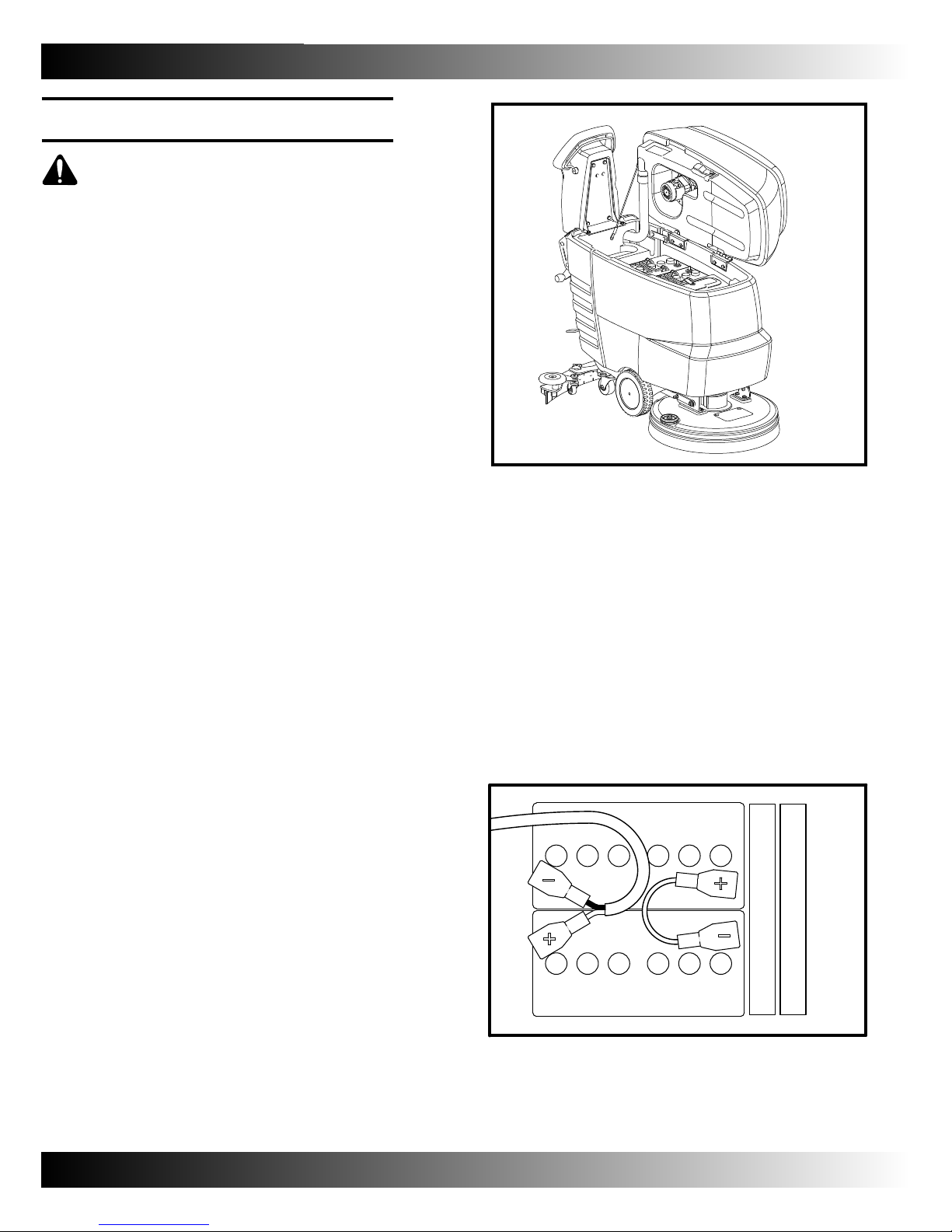
2. Raise recovery tank to access battery
compartment.
3. Install batteries into the battery compartment.
Secure batteries with supplied battery spacers.
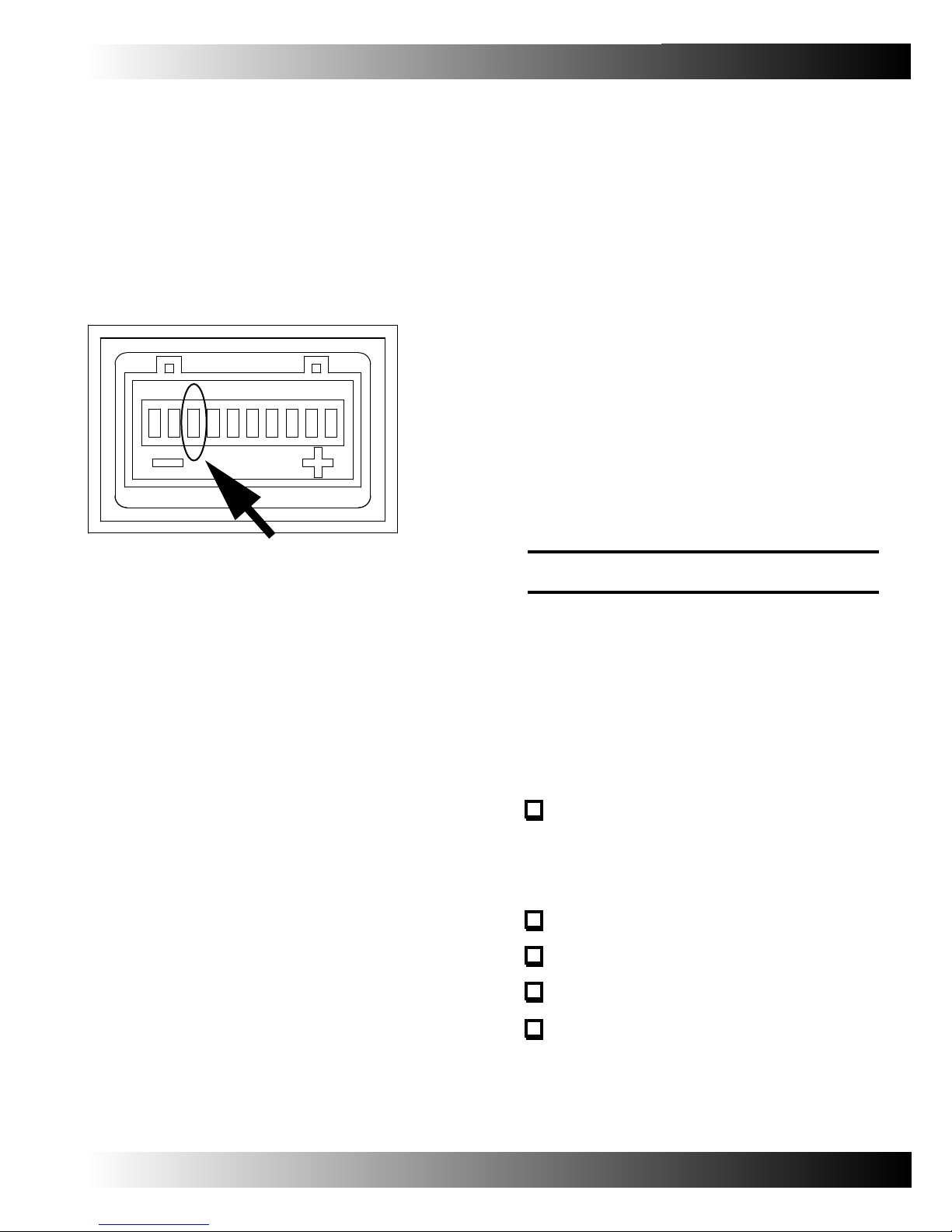
4. Before connecting batteries, make sure terminals
and posts are clean. Use post cleaner and wire
brush if needed.
NOTE: To prevent battery corrosion, apply a light
coating of protective, anti-corrosion spray.
5. Connect battery cables to battery post.
RED TO POSITIVE (+)
BLACK TO NEGATIVE (-)
SPACER
SPACER
6
FRONT OF SCRUBBER
6. After battery installation, check the battery
condition meter.

ATTACHING SQUEEGEE ASSEMBLY
1. Park machine on level surface. Remove
the key.
2. Lift squeegee using the lift lever.
3. Mount squeegee assembly to squeegee bracket
as shown. (Ref. Photo)
OPERATION
4. Connect vacuum hose to the squeegee casting.
5. Check squeegee blades for proper deflection.
(Reference: Squeegee blade adjustment)
7

OPERATION
BRUSH AND PAD SELECTION
Use the correct brush type for your cleaning environment.
Choose from the following brushes and pads.
Non-scuff polypropylene scrub brush - A
softer brush intended for use in general purpose
scrubbing for lightly lifting compacted soilage
without scuffing high-gloss coated floors.
Nylon scrub brush - Recommended for
scrubbing coated floors. Cleans without
scuffing surface.
Super abrasive bristle scrub brush - Nylon
fiber impregnated with abrasive grit for
removing heavy stains and soilage. Strong
action works well on build up, grease,
and/or tire marks.
Heavy duty stripping pad - Intended for
stripping floors. Pad aggressively cuts through
old, heavy, floor finishes in preparation for
re-coating.
Stripping pad - Intended for stripping floors.
Quickly and easily cuts through old finish to
prepare the floor for re-coating.
Scrubbing pad - Intended for scrubbing
floors. Removes dirt, spills and scuffs,
leaving a clean surface ready for re-coating.
Buffing pad - Intended for buffing floors.
Quickly cleans and removes scuff marks
while polishing the floor to a high gloss.
Polishing pad - Intended for polishing floors.
Maintains a high gloss. Use for buffing very
soft finishes and lower traffic areas, or use
for polishing soft waxes on wood floors.
8
BRUSH/PAD INSTALLATION
1. Park machine on level surface, remove the key.
2. With foot, press down on scrub head lift pedal
to raise scrub head from cleaning surface.
3. Turn the brush drive hub until spring clip is in
clear view.
OPERATION
access
flap
spring clip
4. Align pad driver/brush mounting posts into
drive hub slots. Turn the pad/brush driver
counter clockwise until retained by the
spring clip.
Hub/Motor
Opening
Pad Driver/Brush
Mounting Post
Spring Clip
6. To remove pad driver/brush, grasp pad
driver/brush and turn clockwise with a
quick motion.
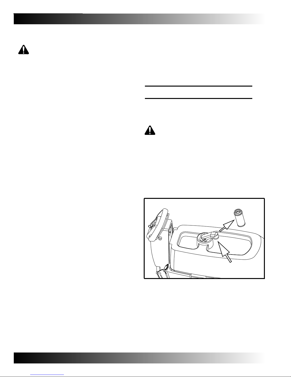
FILLING SOLUTION TANK
A hose fill port is located on the upper right
rear corner of the solution tank.
View sight gauge when filling solution tank
with hose fill port.
The solution tank port is located under the
recovery tank.
Do not fill beyond the bottom edge of the fill port.
(Ref. Arrow 1)
5. Inspect that lock pin is securely located.
Do not open recovery tank if full. First, drain
until empty, then open for solution fill access.
FOR CONVENTIONAL SCRUBBING:
Fill with hot water not to exceed 140° F (60°C).
Mix recommended cleaning detergent into the
solution tank.
WARNING: Fire or Explosion Hazard.
Never Use Flammable Liquids.
FOR SAFETY: Always follow mixing and
handling instructions on chemical containers.
9

OPERATION
MACHINE OPERATION
FOR SAFETY: Do not operate machine,
unless operator manual is read and
understood.
WARNING: Fire or Explosion Hazard.
Never Operate Machine In Or Near
Flammable Liquids, Vapors Or
Combustible Dusts.
1. Turn main power key on ( I ).
2. Lower squeegee assembly level to floor with
the squeegee lift lever. The vacuum motor will
automatically engage when squeegee is lowered.
3. Lower scrub head to floor by depressing scrub
head lift pedal as shown.
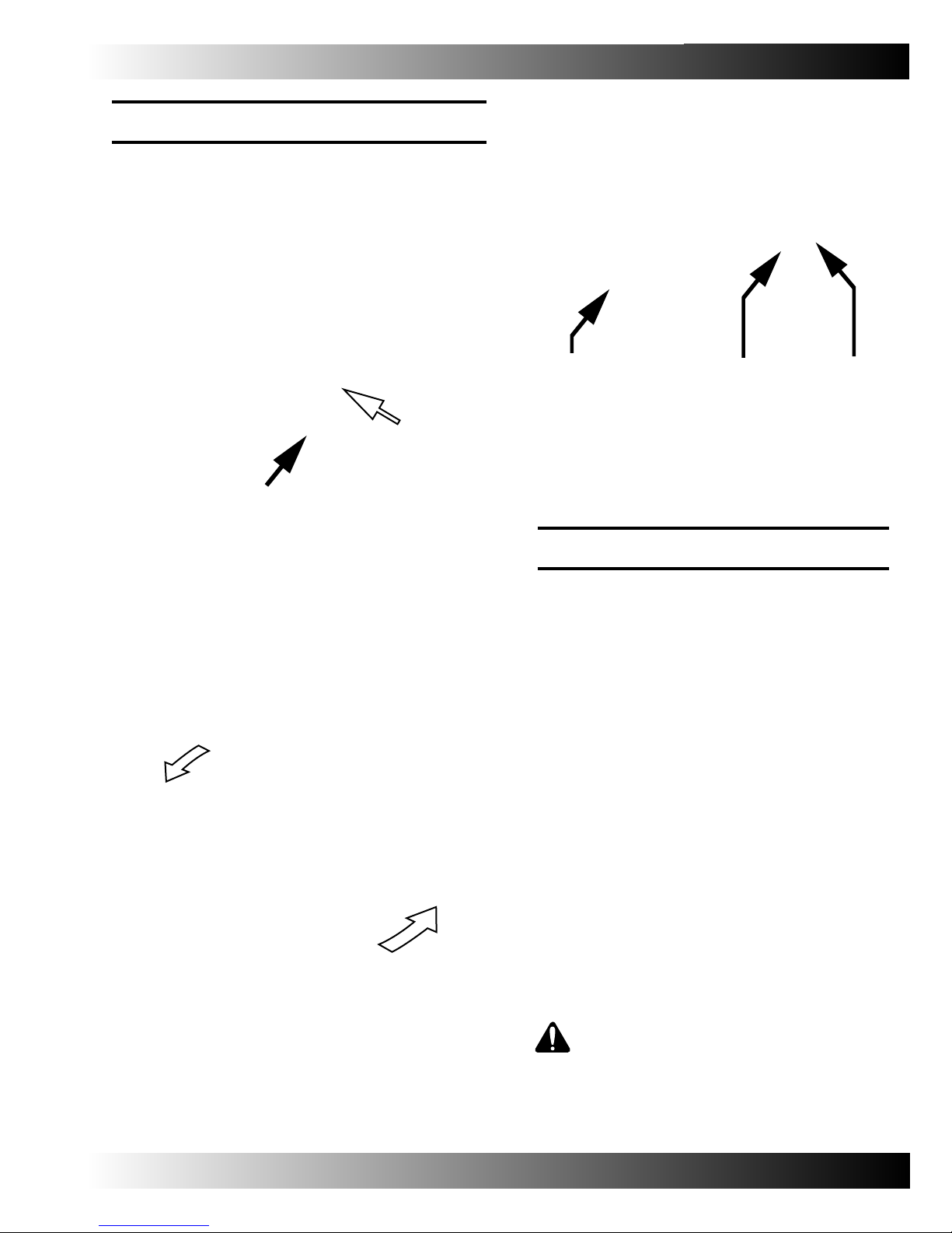
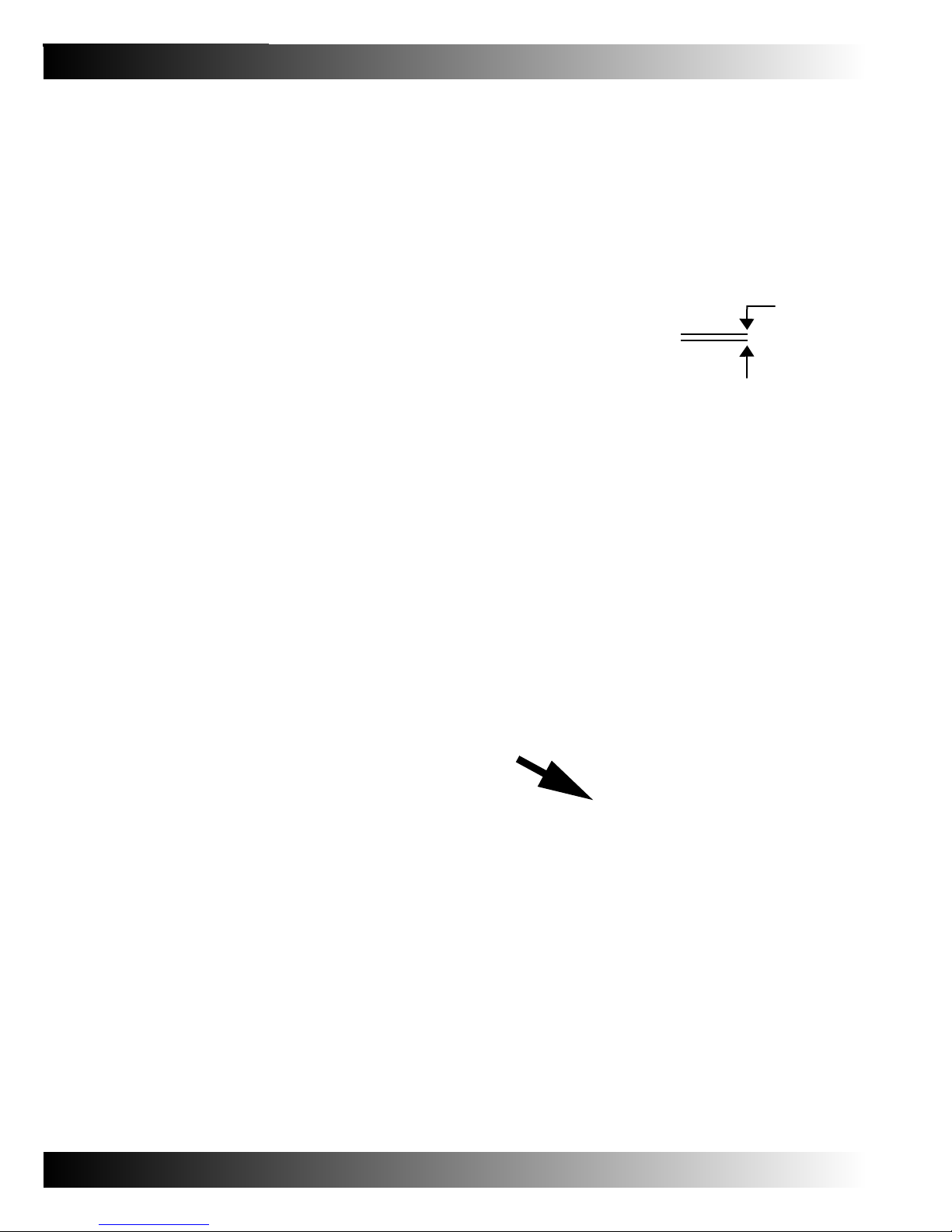
4. To drive machine forward, squeeze the directional
control bar against the handle (Ref Arrow 1).
For reverse, push control bar forward as illustrated
(Ref. Arrow 2).
ReverseForward
5. Adjust the variable speed control knob to the
desired scrub brush speed.
10
6. Turn the solution flow control dial to desired rate.

7. With the brush in the lowered position, the
solution flow and brush will automatically
activate when the scrubber is driven forward
or reverse.
OPERATION
5. Heavily soiled floors may require double
scrubbing. Scrub first with squeegee up,
let solution work for a few minutes.
Scrub the second time with squeegee down.
6. When machine is unattended, park on a level
surface and remove the key.
ATTENTION: Do not allow foam to enter
float screen. Vacuum motor damage may
occur. Foam will not activate float shut off.
DRAINING TANKS
Drain and clean recovery tank after each use.
Clean the solution tank periodically.
8. For increased brush pressure, adjust by lifting
the down pressure lever.
9. To stop scrubbing, release the directional
control bar.
WHILE OPERATING MACHINE
WARNING: Fire Or Explosion Hazard.
Do Not Pick Up Flammable Materials Or
Reactive Metals.
FOR SAFETY: When using machine, manuver
slowly on inclines and slippery surfaces.
Wear non-slip shoes.
1. Overlap scrubbing path by 4 cm (1.5 in).
2. If squeegee leaves streaks, wipe with cloth to
remove debris. Pre-sweeping area is
recommended.
DRAINING RECOVERY TANK
1. Remove recovery tank drain hose cap. Plug
by turning the T-Handle counter-clockwise
to empty.
NOTE: When using a bucket to empty machine,
do not use the same bucket to fill the solution tank.
3. Do not operate machine where grade exceeds
5% (3º).
4. Mix recommended foam control solution
in recovery tank if foaming appears.
2. After empty, open recovery tank cover
and rinse out the tank.
11

OPERATION
DRAINING RECOVERY TANK
1. To drain remaining water from the solution tank,
remove solution tank level hose from the barbed
fitting.
2. To clean out the solution tank, remove the clean
out cap at the rear of the machine and rinse the
tank through the openning in the front of the
recovery tank.
3. To rinse out the solution tank, remove the clean
out cap at the rear of the machine and rinse fill
port under the recovery tank.
CIRCUIT BREAKER / FUSES
The machine is equipped with a circuit breaker.
This breaker is easily reset after preventing
electrical damage during an overload.
The circuit breaker protects the brush motor
It is located on the control panel. If breaker trips,
determine cause, let motor cool, then reset.
The machine is equipped with two fuses. The
fuses are attached to wires hanging in the lower
area inside the control console:
The powered model has a 30A main fuse and a 25
amp vacuum motor fuse.
The brush assist model has a 5A main fuse and a
25A vacuum motor fuse.
12
Contact your dealer or Authorized Service
Center for Machine repairs.
OPERATION
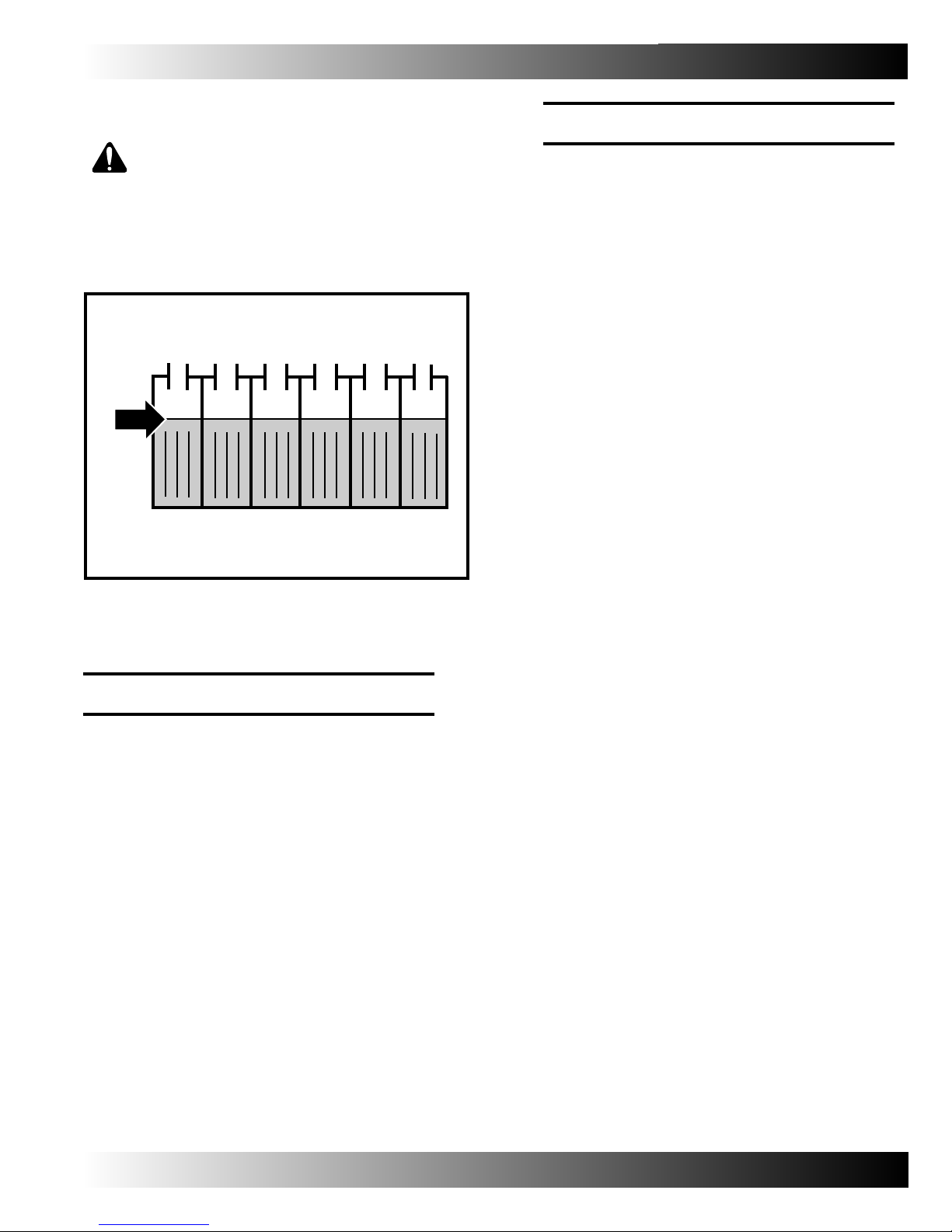
BATTERY METER
The battery meter displays the battery charge
level. When fully charged, all indicator lights
are displayed. As batteries discharge, battery
life will be indicated viewing from right to left.
Do not allow batteries to discharge beyond
illustrated discharge level.
HOUR METER
The hour meter will record only when the brush
motor is on.
At First Red Light, stop and recharge.
The Last Red Light will flash before machine
automatically shuts down.
Drive machine to recharging station immediately.
Scrubbing functions will stop when the last
red light begins flashing.
This automatic function protects batteries
from total battery discharge.
NOTE: Prolong batery life, ONLY recharge
after machine use cycles of 30 minutes or more.
NOTE: If a machine fault is detected, the
battery meter will flash fault codes.
(Ref. LED FAULT CODES)
CHARGING BATTERIES
ATTENTION: Prolong battery life.
ONLY Recharge batteries after a
minimum run cycle of 30 minutes.
Do not leave batteries discharged.
Only use a battery charger with the follow
specifications.
16
#(!2'%2490%
&/2,%!$!#)$"!44%2)%3
&/27%4,EAD!CID"!44%2)%3
/54054#522%.4!-03
/540546/,4!'%6/,43
!54/-!4)#3(54/&&#)2#5)4
&/2$%%0#9#,%"!44%29#(!2').'
For battery charger operating instructions,
refer to the Battery Charger Manual supplied
with the charger.
OPERATION
1. Recharge batteries in a well ventilated area.
WARNING: Fire OR Explosion Hazard.
Batteries Emit Hydrogen Gas. Keep Sparks
And Flames Away. Charge Batteries With
Hood Open.
2. Park machine on level surface, turn key off.
3. Before charging, check water level in each
battery cell.
(Ref. BATTERY MAINTENANCE)
4. When charging, use recovery tank support
stand to ensure ventilation during charging.
NOTE: Machine will not operate while connected
to battery charger.
ATTENTION: Do not disconnect charger cord
from machine receptacle while charger is
operating. If charging must be interrupted,
disconnect charger from wall outlet first.
MAINTENANCE
For optimal machine performance, follow regularly
scheduled maintenance procedures.
WARNING: Electical Hazard. Disconnect
Battery Cables Before Machine Maintenance.
DAILY MAINTENANCE
1. Drain and clean the recovery tank.
5. Connect charger’s AC power supply cord to a
properly grounded receptacle.
6. Connect char
ger’s Red 24 VDC plug to the
machines battery receptacle found above
squeegee lift handle.
7. The charger will automatically begin charging
and turn off when fully charged.
2. Remove and clean float shut off screen located
in the recovery tank.
3. Drain solution tank and rinse with hot water, 60º
(140ºF) max temperature.
14

4. Remove and clean solution tank filter.
Turn counter-clockwise to loosen.
MOTOR MAINTENANCE
OPERATION
2
3. Rotate rear blade to a new wiping edge, reinstall
band.
All motor brushes have a service life of 750 hours.
SQUEEGEE BLADE REPLACEMENT
Both squeegee blades have four usable edges.
When blade edges are worn, unfasten, rotate/flip
tor a new squeegee edge. Replace when all edges
are worn.
1. Remove squeegee assembly from machine.
(Ref. Photo 1)
2. Loosen band clamp, remove band from
squeegee assembly. (Ref. Photo 2)
1
4. To replace front blade, unclamp, remover retainer
strap to access squeegee, then pull off.
15
OPERATION
1
2
2. To adjust caster height rotate knurled knob
for up/down height adjustment.
MM
v
3. With the scrubber in motin, squeegee blades
should deflect as shown.
SQUEEGEE BLADE ADJUSTMENT
The squeegee assembly and blades are set at the
factory. Adjustment may be necessary depending
on surface to be cleaned.
For optimal operation, squeegee assembly casters
must be set as illustrated.
1. To check for proper adjustment, remove
squeegee assembly from machine and place
on a level surface. Measure the distance
between the surface and caster approximately
2 mm (1/16”).
16
OPERATION
BATTERY MAINTENANCE
WARNING: Fire or Explosion Hazard.
Never Operate Machine In Or Near Flammable
Liquids, Vapors Or Combustible Dusts.
1. Check battery fluid level frequently.
STORING MACHINE
1. Fully charge batteries. Never store with
discharged batteries.
2. Drain and rinse tanks.
3. Store in a dry area with squeegee and scrub
head up from surface.
4. Open tanks for air circulation.
ATTENTION: Store indoors, away from
heat and moisture.
2. Clean batteries to prevent corrosion. Use scrub
brush with a mixture of baking soda and water
TRANSPORTING MACHINE
When transporting by truck or trailer, safely
tie down and secure machine.
1. Raise the scrub head and squeegee.
2. Load machine using recommended ramp.
3. Place machine against the front of
transporter.
4. Block each wheel.
5. Use tie-down straps over the top of machine
to prevent tipping.
FOR SAFETY: Use recommended ramp for
loading/unloading. Tie down machine to
transporter.
20
17

OPERATION
LED FAULT CODES (Flashing LED’s)
ODE FAULT SOLUTION
C
One
Low voltage shut-off. Recharge batteries.
Scrubbing function stops. Check battery connection.
Two
Three
Battery charge level getting low. Recharge batteries.
Drive motor tripped. Reset circuit breaker.
Short circuit to drive motor. Contact Dealer.
Four
Eight
Ten
No Bars
Bars Rippling
Battery lockout. Recharge batteries immediately.
Controller tripped. Contact Dealer.
High battery voltage reading. Check battery connections.
Sleep mode. Turn key to restore.
Throttle engaged. Release directional control bar.
SPECIFICATIONS
GENERAL MACHINE DIMENSIONS/CAPACITIES
Length 1283mm (50.6”)
Width (with squeegee) 762mm (30.0”)
Width (without squeegee) 554mm (21.8”)
Width (tanks) 457 mm (18.0”)
Height 1087 mm (42.81”)
Squeegee width 762 mm (30.0”)
Scrubbing path 510 mm (20”)
Solution Tank capacity 41 L (10.8 gal)
Recovery Tank capacity 41 L (10.8 gal)
Weight empty 102 Kg (227 lbs)
Weight with batteries 180 Kg (397 lbs)
BATTERIES
System voltage 24-V
Number of batteries Two
Battery voltage 12-V
Battery amp hour rating 155AH
Maximium run time 3 hours
Total power consumption 30A at 22.7 Kg (50 lbs) brush pressure
37A at 45.3 Kg (100 lbs) brush pressure
18

OPERATION
SPECIFICATIONS
SOLUTION DELIVERY SYSTEM
Solution filter 80 mesh stainless steel
Solution flow control Automatic shut-off solenoid valve
with operator-controlled variable flow rate
BRUSH SYSTEM
Brush size 510mm (20.0”) Diameter
Brush RPM 235 RPM
Brush motor horsepower .74 Kw (1.0 hp)
Brush pressure 22.7 Kg (50 lbs) minimum, 45.3 Kg (100 lbs) Maximum
SOLUTION RECOVERY SYSTEM
Squeegee Curved 762 mm (30.0”) four-sided quick-change blades
Vacuum motor horsepower .37 Kw (.5 hp)
Vacuum CMM (CFM) 1.84 cmm (65 cfm)
Vacuum Maximum water lift 1067 mm (42”)
DRIVE SYSTEM
Vehicle control Electronic variable speed control forward and reverse
Vehicle speed Forward 0 - 4.3 KPH (2.6 MPH)
Reverse 0 - 2.6 KPH (1.6 MPH)
Maximum grade empty 15% (9 degrees)
Maximum grade scrubbing 5% (3 degrees)
Maximum grade transporting 8% (5 degrees)
Transaxle 24-V, 0.104 Kw (0.14 hp)
Tires 203.2 (8.0”) Diameter non-marking polyurethane
Casters 77.0mm (3”)
SOUND RATING
Operator position 68.0 dBa
19

Parts Manual
STRIKER 2010
PN 236683 - Striker 2010 Parts List - Printed in USA 03/18/08

 Loading...