

One World Touch OP 1200, OP 1700, OP 1500 Service Manual

12.1” /15”/17
” Intel
Core 2 Duo
Industrial Panel PC with Versatile Bezel Design
Panel PC
OP 1200/1500/1700
(MB:
PC920
, System Chipset:
Intel
9
45G
)
Service
Manual
(Version
2807
)
Version v
1008
,
August
2
010

Copyright Notice
This publication, including all photographs, illustrations and software, is protected under
international copyright law
s, with all rights reserved. Neither this manual, nor any of the material
contained herein, may be reproduced
without written consent of the
m
anufacturer.
Disclaimer
The information in this document is subject to change without notice. The manufacturer m
akes no
representations or warranties with respect to the contents hereof and specifically disclaims any
implied warranties of merchantability or fitness for any particular purpose. The manufacturer
reserves the right to revise this publication and to make
changes from time to time in the content
hereof without obligation to notify any person of such revision or changes.
Trademarks
All brand
s
and product names used for identification in this document are trademarks or registered
trademarks of their respect
ive companies.
Federal Communications Commission (FCC)
This equipment has been tested and found to comply with the limits for a Class A digital device,
pursuant to Part 15 of the FCC Rules. These limits are designed to provide reasonable protection
agains
t harmful interference in a residential installation. This equipment generates, uses, and can
radiate radio frequency energy and, if not installed and used in accordance with the instructions,
may cause harmful interference to radio communications. However
, there is no guarantee that
interference will not occur in a particular installation. If this equipment does cause harmful
interference to radio or television reception, which can be determined by turning the equipment off
and on, the user is encouraged t
o try to correct the interference by one or more of the following
measures:
Reorient or relocate the receiving antenna.
Increase the separation between the equipment and the receiver.
Connect the equipment onto an outlet on a circuit different from that to
which the receiver
is connected.
Consult the dealer or an experienced radio/TV technician for help.
Shielded interconnect cables and a shielded AC power cable must be employed with this equipment
to ensure compliance with the pertinent RF emission limits
governing this device. Changes or
modifications not expressly approved by the system's manufacturer could void the user's authority
to operate the equipment.
Declaration of conformity
This device complies with part 15 of the FCC rules. Operation is subject
to the following conditions:
This device may not
cause harmful interference,
This device must accept any interference
received, including interference that may cause undesired
operation
© Copyright 200
8 July
Version
2
807
All rights reserved.
Printed in T
aiwan

Unpacking
U
npacking the carton
s,you will see the
OP SERIES
panel PC
cabinets packed in separate cartons.
Remove all the EPE foams stuffed in the cartons and the
panel PC
cabinets. These packing materials
are used
to protect the components from s
winging around
d
uring local transpor
t
ation. It is strongly
recommended
thatthey are kept for future transportation use.
C
heck and see if the following items
are included and in good condition.
OP SERIES
unit
Pedestal set
Accessor
y box
-
Power co
rd
(90o)
x 1
-
Utilities
,
drivers & user manual CD diskette
x 1-Panel mounting kit (optional)
x 1 set
Make sure that all of the items listed above are present. If any of the above items is missing, contact
your dealer immediately.
Warranty
All pr
oducts
produc
ed by the
m
anufacturer
are warranted against defective materials and
workmanship for one year starting from the date of delivery to the original purchaser.
However, this warranty does not apply to: (1) damage caused by accident, abuse, misuse
,
misapplication, (2) the product or part has been modified, (3) the product serial number or
warranty label has been removed or defaced.

Important Safety Precautions
Before getting started, read these instructions and save them for later reference.
1.Toaccess any internal components of the system
, confirm the s
ystem
power is
turned
off
and make sure all the
system
fans already stop turning.
2.
Turn off the computer before cleaning. Clean with a damp or dry cloth only.
Do not spray
any liquid cleaner on scr
een.3.
The power socket used to plug in the power cord must be located near the system and
easily accessible. Do not use outlets on the same circuit of the systems that regularly
switched on
and
off.4.Make sure the voltage of the power source is correct bef
ore connecting the system to the
power outlet.
5.
If the
system
is sharing an extension cord with other devices, make sure the total ampere
rating of the devices plugged into the extension cord does not exceed the cord
’
s ampere
rating.
6.
Do not expose the pow
er cord, power outlet
and exte
nsion cord to moisture.
7.
Install the
system
on a reliable surface to prevent damage caused by dropping.
8.
Disconnect the power cord from the system before any installation. Make sure both the
system and the external devices are t
urned off. The sudden surge of power may ruin any
sensitive components. Also make sure the system is properly grounded.
9.
During installation of any internal components, be sure to ground yourself to keep from
any static charge. Most electronic components
are sensitive to the static electric charge.
Use a grounding wrist strap and place all electronic components in any static
-
shielded
devices.
10.
The openings on the system cabinet are for the cabin ventilation to prevent the system
from overheating.
DO NOT C
OVER THE OPENINGS
.
11.
The brightness of the flat panel display will decrease with use. However, hours of use will
vary depending on the application environment.
12.
Avoid
using sharp objects to operate the touch panel. Scratches on the touch panel may
cause ma
l-ca
libra
tion or non
-
function to the
touch
panel.
13.
The LCD panel display is not subject to shock or vibration. When assembling the computer,
make sure it is securely installed.

Table of Contents
1.
INTRODUCTION
................................
................................
................................
....1-11.1.
G
ENERAL
I
NFORMATION
................................
................................
............................
1-2
1.2.
W
HATCOVERS IN THIS
M
ANUAL
................................
................................
..................
1-3
1.3.
S
PECIFICATIONS
................................
................................
................................
.....1-
4
2.
USING THE SYSTEM
................................
................................
..............................
2-7
2.1.
I
DENTIFYING THE
S
YSTEM
................................
................................
..........................
2-8
2.2.
P
ANEL
PC
I/O
O
UTLETS
................................
................................
...........................
2-9
2.3.OPSERIES
D
IMENSION
................................
................................
........................
2-11
2.3.1.
OP 1200
................................
..............................
Error! Bookmark not defined.
2.3.2.
OP 1500
................................
..............................
Error! Bookmark not defined.
2.3.3.
OP 1700
................................
..............................
Error! Bookmark not defined.
2.4.
P
OWERING UP THE
S
YSTEM
................................
................................
......................
2-13
2.5.
R
UNNING THE
BIOS
S
ETUP
................................
................................
.....................
2-14
2.6.
O
PERATING
S
YSTEM AND
D
RIVER
I
NSTALLATION
................................
.............................
2-143.VERSATILE MOUNTING O
PTIONS
................................
................................
.......
3-15
3.1.
V
ARIOUS
F
RONT
B
EZELS
................................
................................
.........................
3-16
3.1.1.
OP SERIES
with Small Bezel
................................
................................
.........
3-16
3.1.2.
OP SERIES
with Big Bezel
................................
................................
.............
3-17
3.1.3.
Aluminum Alloy Bezel
................................
................................
..................
3-183.2.L-
SHAPE
M
OUNTING
B
RACKETS
................................
................................
.................
3-19
3.2.1.
OP 1200
Panel Mount
................................
................................
...................
3-20
3.2.2.
OP 1500
Panel Mount
................................
................................
...................
3-21
3.2.3.
OP 1700
Panel Mount
................................
................................
...................
3-22
3.3.
W
ALLMOUNTING AND
M
OBILE
A
PPLICATIONS
................................
................................
3-234.KNOCKING D
OWN THE PANEL PC
................................
................................
.......
4-25
4.1.
W
HATCONTAINS IN EACH
M
ODULE
................................
................................
.............
4-26
4.2.
D
ISASSEMBLING THE
P
ANEL
PC
................................
................................
.................
4-26
4.2.1.
Disassembling the Display Module
................................
................................
.4-284.2.2.
Knocking down the panel PC’s Individual Modules
................................
............
4-29
4.2.2.1.
Disassembling the PC I/O Module
................................
................................
..........
4-29
4.2.2.2.
Disassembling the Riser Card Module
................................
................................
....4-304.2.2.3.
Disassemblin
g the Power Supply Module
................................
................................
4-30
4.2.2.4.
Detaching the slim CD
-
ROM/FDD
................................
................................
..........
4-31
4.2.2.5.
Disassembling the Expansion Door
................................
................................
........
4-31
4.2.2.6.
Detaching the HDD
................................
................................
.............................
4-32
4.2.2.7.
Detaching the Touchscreen Controller
................................
................................
....4-324.2.2.8.
Removing CPU & DDR
................................
................................
.........................
4-33
5.
BUILDING UP THE PANE
L PC
................................
................................
..............
5-34
5.1.
D
ISPLAY
M
ODULE
A
SSEMBLY
................................
................................
....................
5-37
5.1.1.
Front Bezel Assembly
................................
................................
...................
5-37
5.1.2.
LCD Module Assembly
................................
................................
..................
5-38
5.1.2.1.
OP 12
00
LCD Assembly
................................
................................
.......................
5-38
5.1.2.2.
OP 1500
/1700 LCD assembly
................................
................................
...............
5-39
5.1.3.
Display Module Integration
................................
................................
...........
5-40
5.2.PCM
ODULE
A
SSEMBLY
................................
................................
...........................
5-41
5.2.1.
Motherboard Assembly
................................
................................
.................
5-42
5.2.1.1.
Installing the CPU
................................
................................
..............................
5-42
5.2.1.2.
Installing the DDR Memory Module
................................
................................
........
5-44
5.2.2.
Touchscreen Controller Assembly
................................
................................
..5-445.2.3.
HDD Module Assembly
................................
................................
.................
5-44
5.2.4.
Power Module Assembly
................................
................................
...............
5-45
5.2.5.
FDD/CD
-
ROM Assembly
................................
................................
................
5-46

5.2.6.
Expansion Door Assembly
................................
................................
.............
5-47
5.2.7.
Riser Card Assembly
................................
................................
....................
5-47
5.2.8.
I/O Module Assembly
................................
................................
...................
5-48
5.2.9.
PC Module Integration
................................
................................
..................
5-49
5.2.9.1.
Motherboard Integration
................................
................................
.....................
5-49
5.2.9.2.
HDD Module Integration
................................
................................
......................
5-49
5.2.9.3.
Touchscreen Controller Integration
................................
................................
........
5-49
5.2.9.4.
Expansion Door Inte
gration
................................
................................
.................
5-49
5.2.9.5.
Display Module Integration
................................
................................
..................
5-50
5.2.9.6.
Slim CD
-
ROM/FDD Integration
................................
................................
.............
5-50
5.2.9.7.
Power Supply Integration
................................
................................
....................
5-51
5.2.9.8.
Riser Card Integration
................................
................................
.........................
5-51
5.2.9.9.
Inverter Co
ver Integration
................................
................................
...................
5-51
5.2.9.10.
I/O Cover Integration
................................
................................
......................
5-51
5.2.9.11.
I/O Cover Integration
................................
................................
......................
5-51
6.
SYSTEM MOTHERBOARD &
I/O BOARDS
................................
.............................
6-52
6.1.OPSERIES
M
OTHERBOARD
................................
................................
....................
6-54
6.1.1.
General Information
................................
................................
....................
6-54
6.1.2.
Specifications
................................
................................
..............................
6-556.1.3.
Locating Jumpers & Connectors
................................
................................
.....6-576.1.4.
How to Set Jumpers
................................
................................
.....................
6-58
6.1.5.
Jumpers & Jumper Setting
................................
................................
............
6-59
6.1.5.1.
JP3:
Clear CMOS (JP3)
................................
................................
........................
6-61
6.1.6.
Connectors & Pin Assignment
................................
................................
........
6-59
6.1.6.1
.
ATXP1: ATX Power Connector
................................
................................
...............
6-63
6.1.6.
2.ATXP2: ATX +12V Power Connector
................................
................................
.......
6-60
6.1.6.
3.CN1: Touchscreen Power Connector
................................
................................
......6-606.1.6.
4.PWR1
: CD-ROM Power Connector
................................
................................
.........
6-60
6.1.6.
5.INV1: LCD Inverter Connector
................................
................................
..............
6-60
6.1.6.
6.USB1
,2
: USB Port Connector
................................
................................
................
6-61
6.1.6.
7.LCD1: LCD Connector
................................
................................
.........................
6-61
6.1.6.
8.IDE1:
PATA Connector for CD
-
ROM
................................
................................
........
6-62
6.1.6.
9.SATA
1~4:
SATA Connector
................................
................................
..................
6-65
6.1.6.
10
COM2
................................
................................
................................
..............
6-63
6.1.6.1
1.COM3
................................
................................
................................
............
6-63
6.1.6.1
2.CD1:
CD Audio IN
................................
................................
..........................
6-63
6.1.6.1
3.IR1: SIR Connector
................................
................................
.........................
6-63
6.1.6.1
4.CN4: Power LED & EXT. KB/MS, USB
................................
................................
..6-646.1.6.1
5.IOINF 1: I/O Connector
................................
................................
....................
6-64
6.1.6.1
6.EISA1: PCI/ISA Expansion Slot
................................
................................
..........
6-65
6.1.6.1
7.FAN 1~3: FAN Connector
................................
................................
..................
6-67
6.1.6.1
8.
CN3:ATX Power on switch
................................
................................
................
6-67
6.1.6.
19.RST1: Reset System Connector
................................
................................
.........
6-70
6.1.6.2
0.CN2: External LAN Wake
-up................................
................................
..............
6-70
6.2.OPSERIES
I/O
B
OARDS
................................
................................
.......................
6-68
6.2.1.
I/O Board IO
-
005
................................
................................
........................
6-69
6.2.1.1.
Jumpers & Jumper Setting
................................
................................
...................
6-69
6.2.1.2.
CN4: EXT. Connector
................................
................................
..........................
6-69
6.2.2.
IO Board
-
IO006
................................
................................
..........................
6-70
6.2.2.1.
Jumpers & Jumper Setting
................................
................................
...................
6-70
6.2.2.2.
CN6: EXT. Connector
................................
................................
..........................
6-70
6.2.3.
Connectors & Pin Assignment
................................
................................
........
6-72
6.2.3.1.
Keyboard: PS/2 KB Connector
................................
................................
..............
6-73
6.2.3.2.
Mouse: PS/2 Mouse
................................
................................
............................
6-73
6.2.3.3.
COM1, COM2, COM4 (DB
-9)................................
................................
.................
6-73
6.2.3.4.
DC Power: DC Power Output
................................
................................
...............
6-73
6.2.3.5.
LPT1: D
-
SUB-25 Parallel Port
................................
................................
...............
6-73
6.2.3.6.
CRT: VGA (D
-
SUB 15 Pin)
................................
................................
....................
6-74
6.2.3.7.
FDD: External FDD Connector
................................
................................
..............
6-74

6.2.3.8.
J11: USB 1, USB2 Connector
................................
................................
...............
6-74
6.2.3.9.
DIO1: RJ
-
11 Connector
................................
................................
.......................
6-74
6.2.3.10.
LAN1: RJ
-
45 Ethernet Connector
................................
................................
........
6-74
6.2.3.11.
MIC1
................................
................................
................................
.............
6-74
6.2.3.12.
LINE 1
................................
................................
................................
...........
6-75
6.2.3.13.
SPK 1
................................
................................
................................
............
6-75
7.
BIOS SETUP UTILITY
................................
................................
..........................
7-77
7.1.
A
BOUT THE
BIOS
S
ETUPUTILITY
................................
................................
..............
7-77
7.2.
C
ONTROL
KEYD
EFINITION
................................
................................
.......................
7-79
7.3.
G
ETTING
H
ELP
................................
................................
................................
.....7-807.3.1.
Main Menu
................................
................................
................................
..7-807.4.
AWARD
BIOS
S
ETUP
................................
................................
...........................
7-80
7.4.1.
Entering the Setup Utility
................................
................................
.............
7-80
7.4.2.
Standard CMOS Features
................................
................................
..............
7-80
7.4.3.
Advanced BIOS Features
................................
................................
..............
7-84
7.4.4.
Advanced Chipset F
eatures
................................
................................
...........
7-87
7.4.5.
Integrated Peripherals
................................
................................
.................
7-89
7.4.6.
Power Management Setup
................................
................................
............
7-91
7.4.7.
PnP/PCI Configuration
................................
................................
..................
7-94
7.4
.8.
PC Health Status
................................
................................
.........................
7-95
7.4.9.
Load Fail
-
Safe Defaults
................................
................................
................
7-97
7.4.10.
Load Optimized Defaults
................................
................................
...............
7-98
7.4.11.
User Password
................................
................................
............................
7-99
7.4.12.
Save and Exit Setup
................................
................................
..................
7-100
7.4.13.
Exit Without Saving
................................
................................
...................
7-1018.SOFTWARE & DRIVERS I
NSTALLATION
................................
............................
8-105
8.1.
S
YST
EMCHIPSET
D
RIVERS
................................
................................
....................
8-1068.2.E
THERNET
D
RIVERS
................................
................................
.............................
8-1068.3.PC
920
AGP
XGA
................................
................................
..............................
8-1078.4.A
UDIO
S
ETUP
................................
................................
................................
....8-
1088.5.T
OUCHSCREEN
D
RIVERS
................................
................................
.......................
8-1098.6.D
RIVER
I
NSTALLATION
................................
................................
..........................
8-110
APPENDIX
................................
................................
................................
..............
8-111
A:
LCD
S
PECIFICATION
................................
................................
................................
8-111B:DIO
(D
IGITAL
I
NPUT
&
O
UTPUT
)
................................
................................
.................
8-117
C:
D
ISKONCHIP
I
NSTALLATION
................................
................................
.....................
8-118
D:
S
YSTEM
I/O
P
ORTS
................................
................................
................................
.8-
119E:W
AKE
-
ON-
LAN
................................
................................
................................
......
8-120F:F
IRST
MB
M
EMORY
MAP................................
................................
............................
8-123G:P
OWER
S
UPPLY
................................
................................
................................
......
8-124


Service
Manual ver
sion
1008
OP 1200/15
0
0/170
0
(PC920 Intel 945G)
1-1
11..IInnttrroodduuccttiioon
n
This chapter provides back
ground information
and detai
l specification on the
OP SERIES
.
Sections in this chapter include:
General Information
What covers in this Manual
Specification
Dimension

Service
Manual version
1008
OP 1200/15
0
0/170
0
(PC920 Intel 945G)
1-2
1.1.
General Information
The information revolution
that
started from the mid '90s inaugurat
ed a new competitive era
where consumer computing technology was exploited to do business operation quicker than ever
before. Many enterprises from life
-
related industries such as
Photo printing
,Ba
nking
,
Medical
to
POS
,
Kiosk
,
Security
,
Advertising
… etc
. all are eager or forced to automate their industries
with computers in order to thrive in this new age.
For their industrial automation, there is one
thing in common, i.e. space is always a premium and system stability is always a must in their
environme
ntal applications.
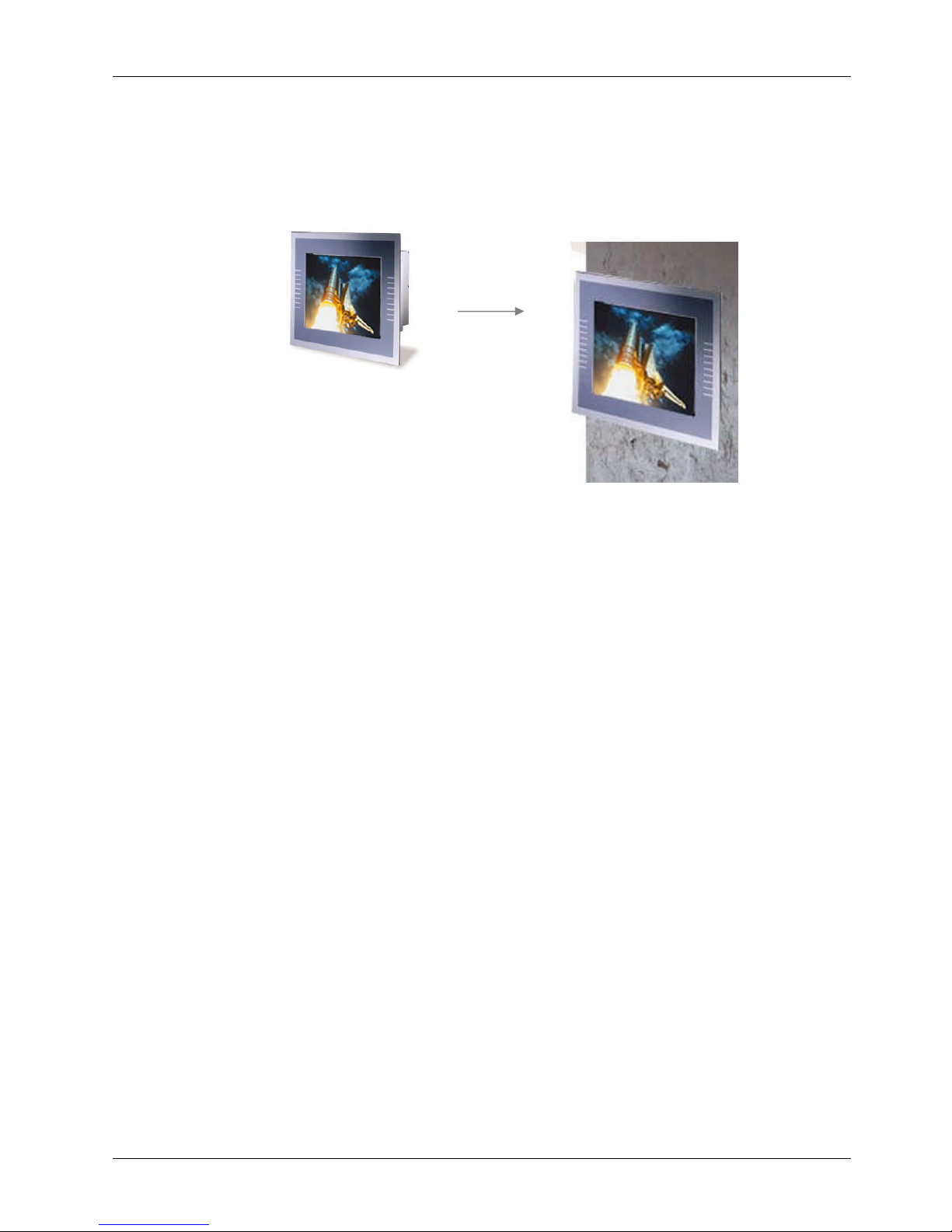
Fully configurable and with its versatile front bezel design, the
OP SERIES
system is an ideal
solution platform for any customized integration and industrial automation.
The small bezel is
mainly designed for Kiosk integration when the
Kiosk cabinet is with a curve surface. The big
bezel is for panel mounting or for Kiosk integration when the Kiosk cabinet is of flat surface and
allows the computer to be fixed to the Kiosk cabinet directly from inside. The aluminum alloy
bezel is mainly
designed for panel mounting in any industrial floor.

Service
Manual ver
sion
1008
OP 1200/15
0
0/170
0
(PC920 Intel 945G)
1-3
1.2.
What Covers in this Manual
Thisservice manual provides service information for the
OP SERIES
panel PC
.
This manual is designed
to help trained service personnel to locate and fix failing parts on th
e
OP SERIES
.
Only service
technicians are allowed to open the system for service
.
You do not need to read everything in this
handbook to
service
the system.
For a quick start, see the following chapter summaries;
Chapter 1
(the current chapter) provides
background information and detail specification on the
OP
1200
/150
0
/1700.
Chapter 2
identifies the
OP SERIES
system exterior components and provides instructions to help
you to use the system as soon as possible.
Chapter 3
details the panel PC’s various m
ounting options by graphical illustrations.
Chapter
4
helps you to
knock down the
system
into parts
to access components
.
Chapter
5
helps you to
build up the panel PC
.
Chapter
6
provides detail information of the jumper settings and connector signals of t
he system
control board
and I/O boards
.
Chapter
7
explains the AWARD BIOS setup.
Chapter
8
introduces the Ethernet, XGA
, audio
and
touchscreen
drivers.
Appendix A
introduces
the
built
-inLCD.
Appendix B
introduces the system
’
s onboard DIO.
Appendix
C
intro
duces the DiskOnChip
installation.
Appendix
D
introduces the Wake
-On-
LAN feature.
Appendix
E
describes the system IO port address
Appendix
F
explains the first MB memory map.
Appendix
G
provides the specifications for the built
-
in power supply.

Service
Manual version
1008
OP 1200/15
0
0/170
0
(PC920 Intel 945G)
1-4
1.3.
Specifica
tions
OP SERIES
:
12.1”
/15”/17
” TFT Intel
®
C
ore 2 Duo
industrial
panel PC with
v
ersatile
bezel
design
CPU
Intel
Celeron 2.0 GHz up to Core 2 Duo 2.
6
GHzMotherboard
: PC
920
System Chipset
: Intel
9
45G&ICH7
System BIOS
:
Award PnP Flash BIOS
System Memory
: 2*240
pin DDR
2
socket supporting system memory up to
4GB
Display Module
OP 1200
12.1
” color TFT,
800*600
Luminance (cd/m2)
: 400
or above
OP 1500
15” color TFT, 1024*768
Luminance (cd/m2)
:25
0 or above
OP 1700
17”color TFT, 1
280*1024
Luminance (cd/m2)
:420o
r above
Integrated 2D/3D graphics engine, 4X AGP
Supports Dynamic Video Memory Technology (DVMT)
Supporting LCD/VGA
Standard I/Os
Serial ports x 4: COM 1, 2 & 4 with +5V/12 power output on pin #9, COM 3 internal type
reserved for touchscreen, COM2 RS
-
232/485 jumper selectable
Parallel
p
ort x 1: supports SPP/EPP/ECP
External FDD
i
nterface x 1
External IDE interface
+5V/+12V DC
-
out x 1
PS/2
k
eyboard
i
nterface x 1
PS/2
m
ouse
i
nterface x 1
DIO: Input x 2, output x 2
USB
i
nterface x 2
VGA
i
nterface x 1
Brig
htness VR x 1
Audio
Speaker
x 2Speaker
-
out,
line-in &
MIC-inEtherne
t100/10 Base
-
T PnP Ethernet with RJ
-45Support
sWake-on-LAN

Service
Manual ver
sion
1008
OP 1200/15
0
0/170
0
(PC920 Intel 945G)
1-5Expansion Slot
PCI*2
Audio Function
Full duplex and independent sample rate converter for audio recording & playback
Supp
orts Microsoft DirectSound
3D positional audio effects
Hi-
performance, mixed
-
signal stereo
MIC-In,speaker
-out,line-InPin header for CD
-
audio in
Hardware Monitor
Monitor
s
processor & system
temperature
Monitor
s
5VSB, VBAT, 1.5V, 3.3V, +5V,
+12V
and pro
cessor voltages
Monitors processor
and
chassis fan speeds
Control
s
processor
,
chassis fan speed and failure alarm
Automatic fan on/off control
Read
-
back capability that displays temperature, voltage and fan speed
Support
s
Intel processor thermal diode outp
ut (real processor temperature)
Power Supply
:
ATX
250W(@25
o
C),220W(@50
o
C),
100~240V/
5~3
A @
50~
60Hz
Touchscreen
(optional, sharing COM3)
12.1”
/15”/17
” analog resistive type with RS
-
232 controller
15”
/17
” surface acoustic wave type (SAW)
Drive Bay
3.5"HDD
SATA interface
Slim CD
-
ROM or equivalent device

Service
Manual version
1008
OP 1200/15
0
0/170
0
(PC920 Intel 945G)
1-6
MECHANICAL & ENVIRONMENTAL
Construction
:
Heavy
-
duty steel
Dimension
(chassis only, unit: mm)
OP 1200
: 354*283*115 (L*W*D)
OP 1500
: 395*320*127 (L*W*D)
OP 1700
: 426*350*130 (L*W*D)
Front Bezels
OP 1200
S
: 354*283 mm (small bezel)
OP 1500
S: 395*320 mm (small bezel)
OP 1700
S: 426*350 mm (small bezel)
OP 1200
B: 405*330 mm (big bezel)
OP 1500
B: 448*371 mm (big bezel)
OP 1700
B: 478*401 mm (big bezel)
OP 1200
A: 405*330 mm (aluminum bezel)
OP 1500
A: 448*371 mm (
aluminum bezel)
OP 1700
A: 478*401 mm (aluminum bezel)
Mounting
Panel mount with mounting kits
Wall mount with swing arm: standard VESA mounting holes (75*75 mm)
ToKiosk
enclosure
Specifications are subject to change without notice.

Service
Manual ver
sion
1008
OP 1200/15
0
0/170
0
(PC920 Intel 945G)
2-7
22..UUssiinnggtthheeSSyysstteem
m
Identifying the System
Panel PC
I/O outlets
Panel PC dimension
Powering up the System
Running the BIOS Setup
Operating System & Driver Installation
Service
Manual version
1008
OP 1200/15
0
0/170
0
(PC920 Intel 945G)
2-8
2.1.
Identifying the System
Before getting started, take a moment to familiarize yourself with the system and
the I/O
arrangement of the
OP 1200
/1500/17
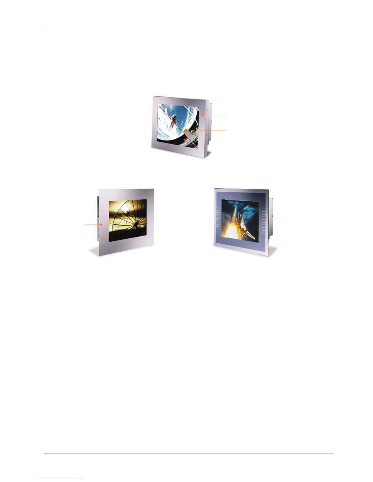
00.The
OP SERIES
’s front view appears as below.
The illustrations of the
OP 1200
/1500/17
0
0 may differ slightly because the
OP SERIES
system series
has three different LCD size: 12.1”
, 15”& 17
”.OPSERIES
FRONT
OP
SERIES
WITH SMALL BEZEL
12.1”/15.
0
”/17.0”
LCD & Touchscreen
Small
bezel
Aluminum
bezel
Aluminum
bezel
OP
SERIES
WITH
BIG
BEZEL
OP
SERIES
WITH
ALUMINUM
Service
Manual ver
sion
1008
OP 1200/15
0
0/170
0
(PC920 Intel 945G)
2-9
2.2.
Panel PC
I/O Outlets
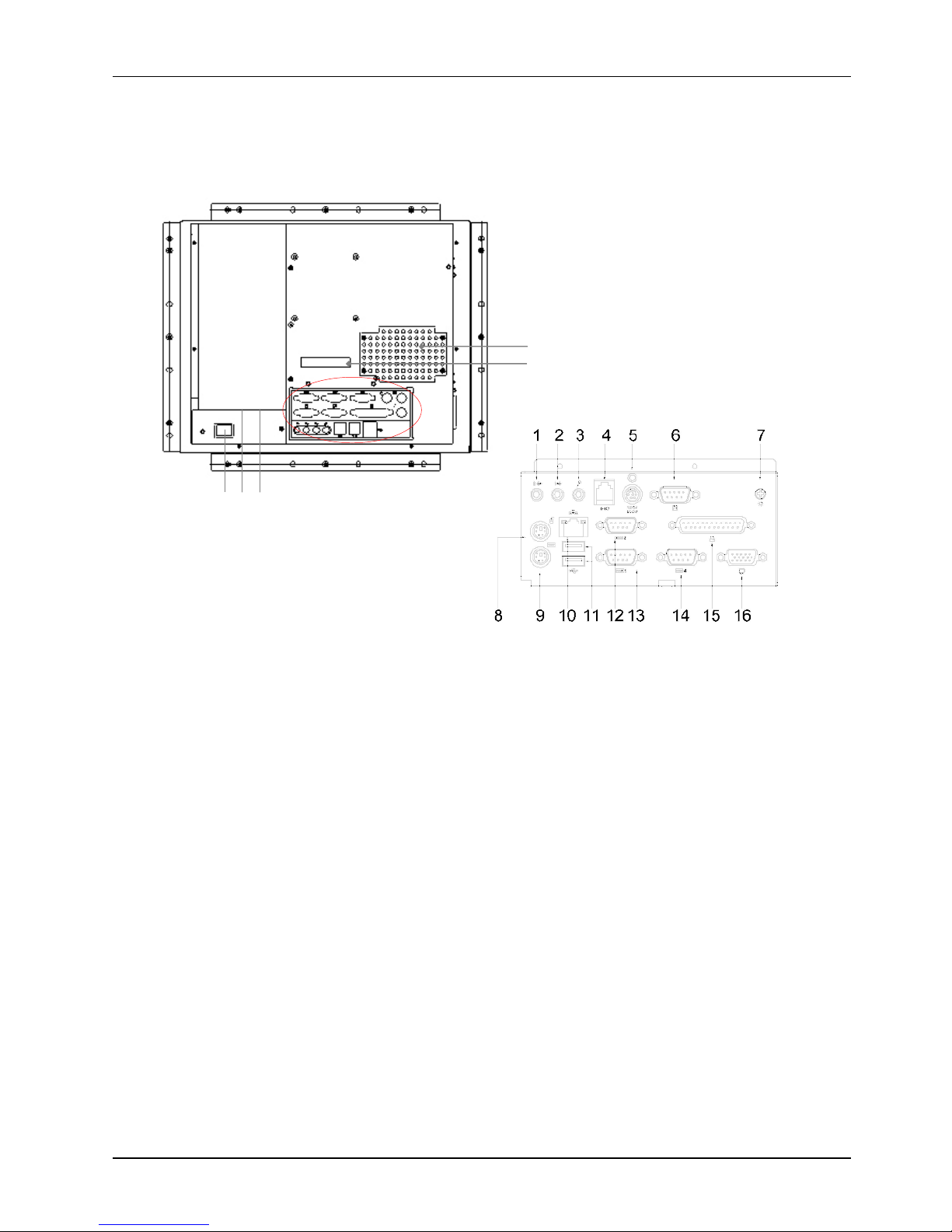
When you turn around the
OP SERIES
system, you will find the power switch and all the I/O ports are
located at the rear cover of the panel PC.
1. Speaker
-
out
2. Line
-in3. MIC
-in4.2-
channel DIO
5. +5/12V DC
-
out
6. External FDD
7. VR brightness
8. PS/2 Mouse
9. PS/2 Keyboa
rd
10. Ethernet (RJ
-
45)
11. USB*2
12.
COM 1
13. COM
2
14. COM
4
15. Printer port
16. VGA port
17. External IDE
18.PPC power switch
19.
Power supply switch
20.AC inlet
D
ust filter
1
7
1
8 19 20

Service
Manual version
1008
OP 1200/15
0
0/170
0
(PC920 Intel 945G)
2-10
1.
Speaker
-
out: This jack is to output the audio to external devices such as speakers or earphones.
2.
Line-in: This jack is used to input audio from an external audio device such as a CD player, tape
recorder or a radio.
3.
MIC-in: This jack is used
to record sound or voice by connecting to an external microphone
.4.DIO: The system provides 2
-
channel digital input and output.
5.
+5V/12V DC
-
out: The DC
-
out
can provide +5V/12 power source for peripheral devices such as
smart card reader and scanner.
6.
External
FDD: This port is provided to connect to an external floppy disk drive. An optional FDD
cable is needed to connect a standard 3.5” FDD to the system.
7.
VR brightness control: This knob is to control the brightness of the LCD screen.
8.
PS/2 Mouse: This port i
s for PS/2 mouse connection.
9.
PS/2 Keyboard: This port is for PS/2 keyboard connection
.
10.
Ethernet (RJ
-
45): The system provides a 100/10 Base
-
T Ethernet interface.
11.
USB*2: These two ports are for USB device connection.
12.
COM1: This port is for serial device co
nnection.
13.
COM2: This port is for serial device connection.
14.
COM4: This port is for serial device connection.
15.
Printer Port: This port is provided to connect to a parallel device.
16.
VGA port: This port is provided to connect to an analog monitor.
17.
External IDE
:
This port is for external IDE device connection.
18.
System p
ower switch
19.
Power supply switch
20.
AC inlet
TheseI/O interfaces are used to connect external peripheral devices
.
Before
connecting any devices
to the
panel PC
, make sure the
system
and the peripher
al devices are turned off.
If there are any
retaining screws on the device cables, make sure they are properly fastened to the secure bolts on the
sides of each port. You might need to install drivers for the new devices.
Refer to the p
eripheral
devices
m
anual
s
for instruction to configure the operation environment to recognize the new attached
devices.

Service
Manual ver
sion
1008
OP 1200/15
0
0/170
0
(PC920 Intel 945G)
2-11
2.3.
OP SERIES
Dimension
2.3.1.
OP 1200
The
OP 1200
’s chassis size is shown below. This does not include the dimension of the
bezel
.
2.3.2.
OP 1500
The
OP 1500
’s chassis size is shown below. This does not include the dimension of the
bezel
.
OP 1200
DIMENSION
OP 1500
DIMENSION
Service
Manual version
1008
OP 1200/15
0
0/170
0
(PC920 Intel 945G)
2-12
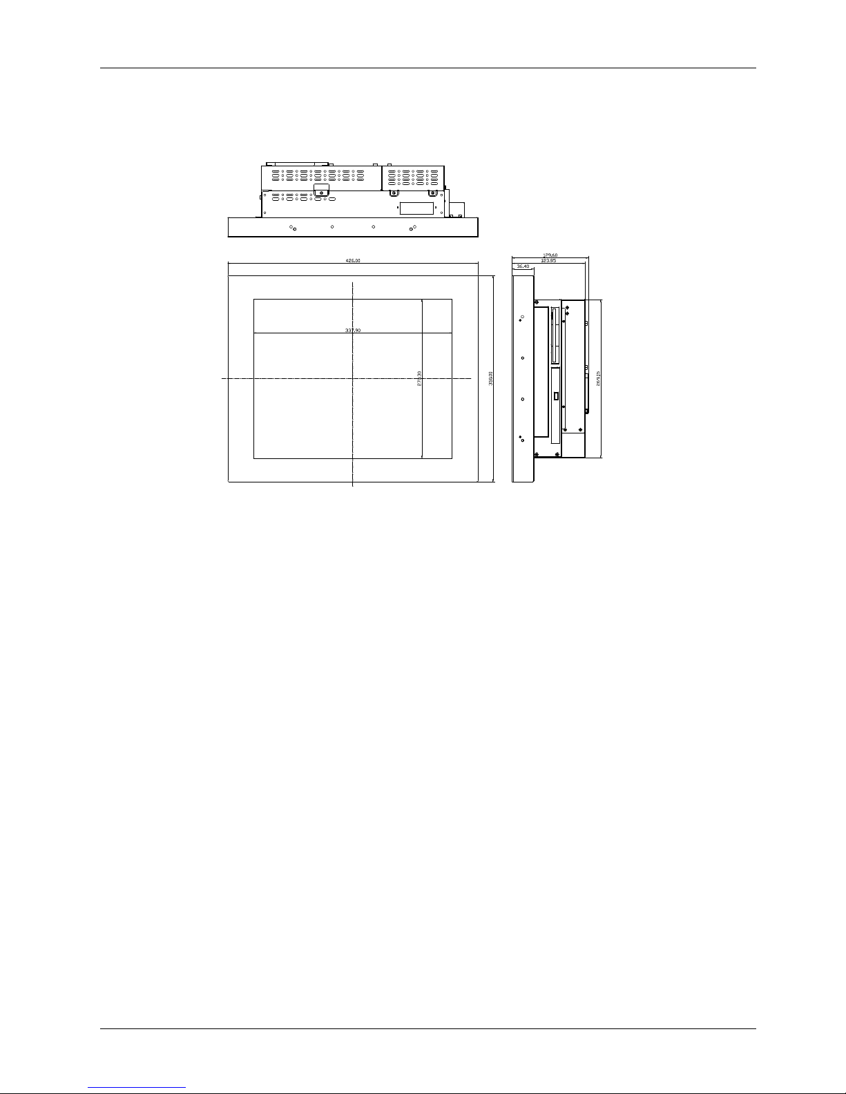
2.3.3.
OP 1700
The
OP 1700
’s chassis size is shown below. This does not include the dimension of the
bezel
.
OP 1700
DIMENSION

Service
Manual ver
sion
1008
OP 1200/15
0
0/170
0
(PC920 Intel 945G)
2-13
2.4.
Powering up the System
Upon rec
eipt of the
OP SERIES
, the system should have been properly set up and configured by
your dealer.
To power up the system, follow the procedures below.
1.
Find the power cord from the accessory box. Connect the
3-pin female end of the power cord to the AC
inlet
located
at the
right rear lower side of
the panel
PC.
Plug the 3
-
pin
male end to an AC power socket.
2.
If there are any other peripheral devices connected to the
system, make sure all the device cables are properly
retained and
connected
to the panel
I/O ports.
3.
Power on the external peripheral devices first.
4.
When facing the system, from your point of view, the power switch is at the right rear lower
side of the panel
PC
. Press the power switch.

Service
Manual version
1008
OP 1200/15
0
0/170
0
(PC920 Intel 945G)
2-14
2.5.
Running the BIOS Setup
If you are a commercial use
r, the
OP SERIES
system
should have been properly set up and configured
by your dealer. You may still find it necessary to change the system configuration information. In this
case, you need to run the system’s BIOS setup program.
Under the following co
nditions, the CMOS settings are to be changed.
1.
The system is starting for the first time.
2.
The hardware de
vices attached to the
OP SERIES
system have been changed.
3.
The CMOS memory has lost power and the configuration information has been erased.
The BIOS se
tup program is stored in ROM, which can be accessed by pressing <DEL> key on the
keyboard immediately when the system is powered on.
In order to retain the specified setup information when the system power is turned off, the system
setup information is st
ored in a battery
-
backed CMOS RAM. The battery is to ensure the settings will
not be erased when the computer is turned off or reset. When the computer is powered on again, the
system will read the settings stored in the CMOS RAM and compare them to the
equipment check
conducted during the power on self
-
test (POST). If any error or mismatch occurs, an error message
will be shown on the screen and the computer will be prompted to run the setup program.
To change the BIOS setup, please refer to
Chapter 7
f
or more information.
2.6.
Operating System and Driver Installation
The
OP SERIES
system is not equipped with an operating system when delivered from the original
manufacturer. If you are a commercial user, the system is likely to have been pre
-
installed prop
er
operating system and software drivers by your dealer or system integrator.
If the system is not pre
-
installed with any system OS and drivers or you intend to install your
preferred ones, there are several ways to load OS and software into the system.
1.
Via
an USB data
-
retrieval devices
2.
Via the CD
-
ROM
3.
Via Ethernet
Recent releases of operating systems always include setup programs that load automatically and
guide you through the installation. You can also refer to your OS user manual for instructions on
formatting or partitioning the hard disk drive before any software installation.
The
OP SERIES
system provides the following utility drivers stored in the CD
-
ROM diskette or utilities
diskettes;
Ethernet utilities
VGA utilities
Audio drivers
Touchscreen d
rivers

Service
Manual ver
sion
1008
OP 1200/15
0
0/170
0
(PC920 Intel 945G)
3-15
33..VVeerrssaattiilleeMMoouunnttiinnggOOppttiioonns
s
TheOP SERIES
system is designed for universal
mounting to fit into different system enclosures for
various environmental applications. This chapter
highlights the steps of different mounting alternatives of
the
OP SERIES
system. Sections include
Different Front Bezels
Mounting
Brackets
Panel Mount
Service
Manual version
1008
OP 1200/15
0
0/170
0
(PC920 Intel 945G)
3-16
3.1.
Various
Front Bezels
The standard
OP SERIES
systems provide
three
kinds of front bezel
s
for different environmental
applications.
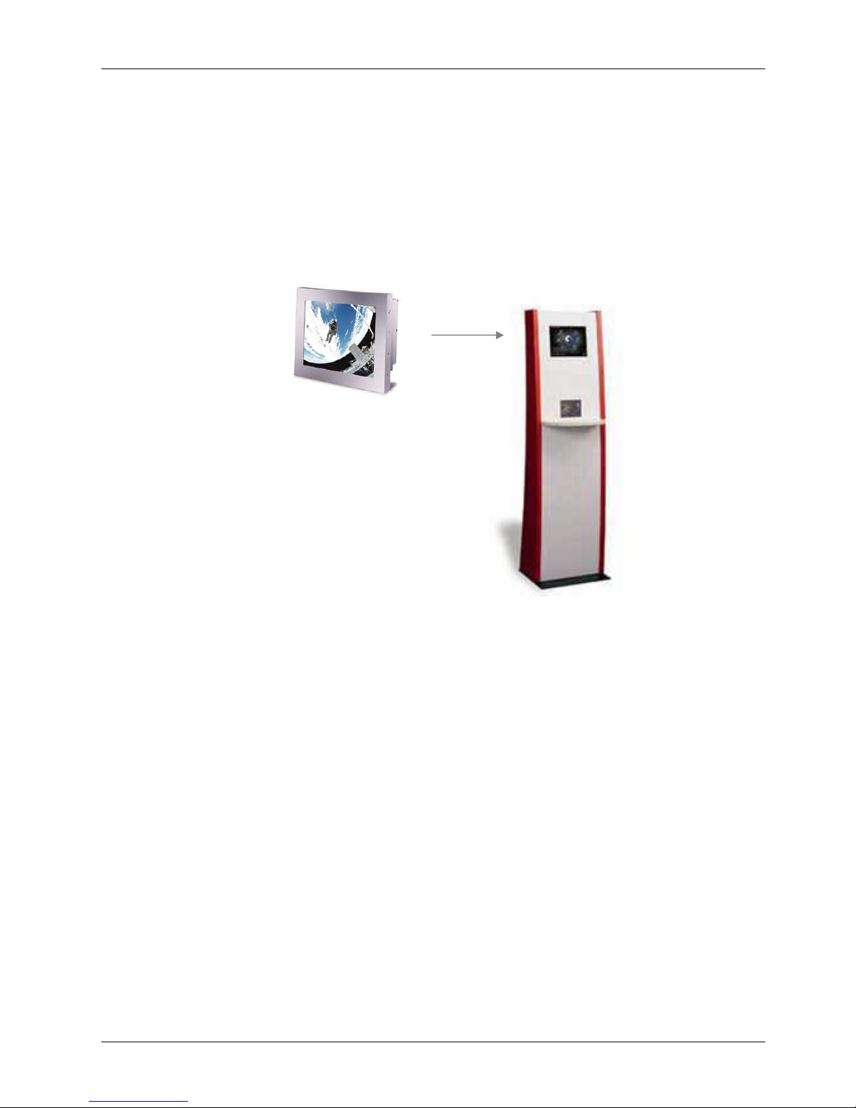
3.1.1.
OP SERIES
with
Small Bezel
The
OP SERIES
S
is an industrial panel PC integrated with a small bezel. The front bezel size is
identical to the computer’s chassis size. This type of bezel is mainly designed for Kiosk integration
when the Kiosk cabinet is with a curve surface and does not allow a bi
g bezel computer to be fitted in.
When integrating the
OP SERIES
S system into the Kiosk
cabinet
,
the
integrator may need to design
special metal brackets per the
cabinet
’s specific mechanism in order to fix the
OP SERIES
system to
the
Kiosk cabinet
.
``
OP
SERIES
SMALL

Service
Manual ver
sion
1008
OP 1200/15
0
0/170
0
(PC920 Intel 945G)
3-17
3.1.2.
OP SERIES
with Big Bezel
The
OP SERIES
B
is an industrial panel PC with a big bezel. The front bezel size is larger than the
computer’s chassis size. Th
is
type of bezel is mainly designed for panel mounting or for Kiosk
integ
ration when the Kiosk cabinet is of flat surface and allows the computer to be fixed to the Kiosk
cabinet directly from inside.
When integrating the
OP SERIES
B system into the
Kiosk cabinet
, the integrator can either use the
provided metal brackets or des
ign special metal
brackets
per the
cabinet
’s specific mechanism in
order to fix the
OP SERIES
system to the
Kiosk cabinet
.OPSERIES
BIG
Service
Manual version
1008
OP 1200/15
0
0/170
0
(PC920 Intel 945G)
3-1
8
3.1.3.
Aluminum Alloy Bezel
The
OP SERIES
A
is an industrial panel PC with an aluminum alloy bezel. Th
is
aluminum alloy bezel
is mainl
y designed for panel mounting. It not only strengthens the system’s framework but also
beautifies the system outlook when the system is panel mounted.
OP
SERIES
ALUMINUM ALLOY
Service
Manual ver
sion
1008
OP 1200/15
0
0/170
0
(PC920 Intel 945G)
3-19OPSERIES
S
M
OUNTING WITH
L
-
SHAPE MOUNTING
B
RACKETS
Mounting brackets
to be mounted here
OP
SERIES
B
M
OUNTING WITH
L
-
SHAPE MOUNTING
B
RACKETS
Mounting brackets to
be mounted here
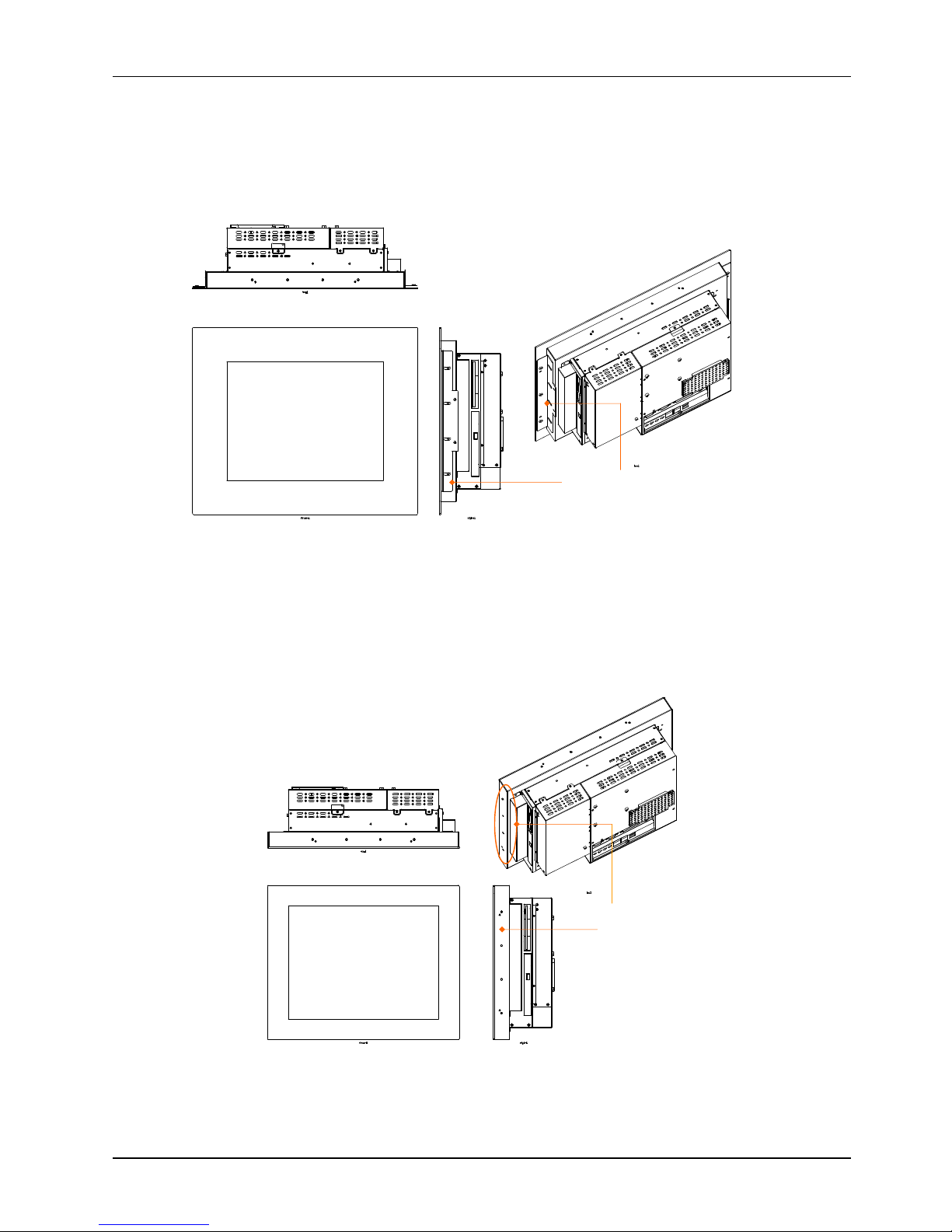
3.2.L-
shape
Mounting Brackets
The
OP SERIES
system provides a pair of L
-
shape mountin
g brackets for system panel mounting. On
the chassis sides, there are at least 4 screw holes on each side used to fix the metal brackets and the
chassis together.
`
Service
Manual version
1008
OP 1200/15
0
0/170
0
(PC920 Intel 945G)
3-20
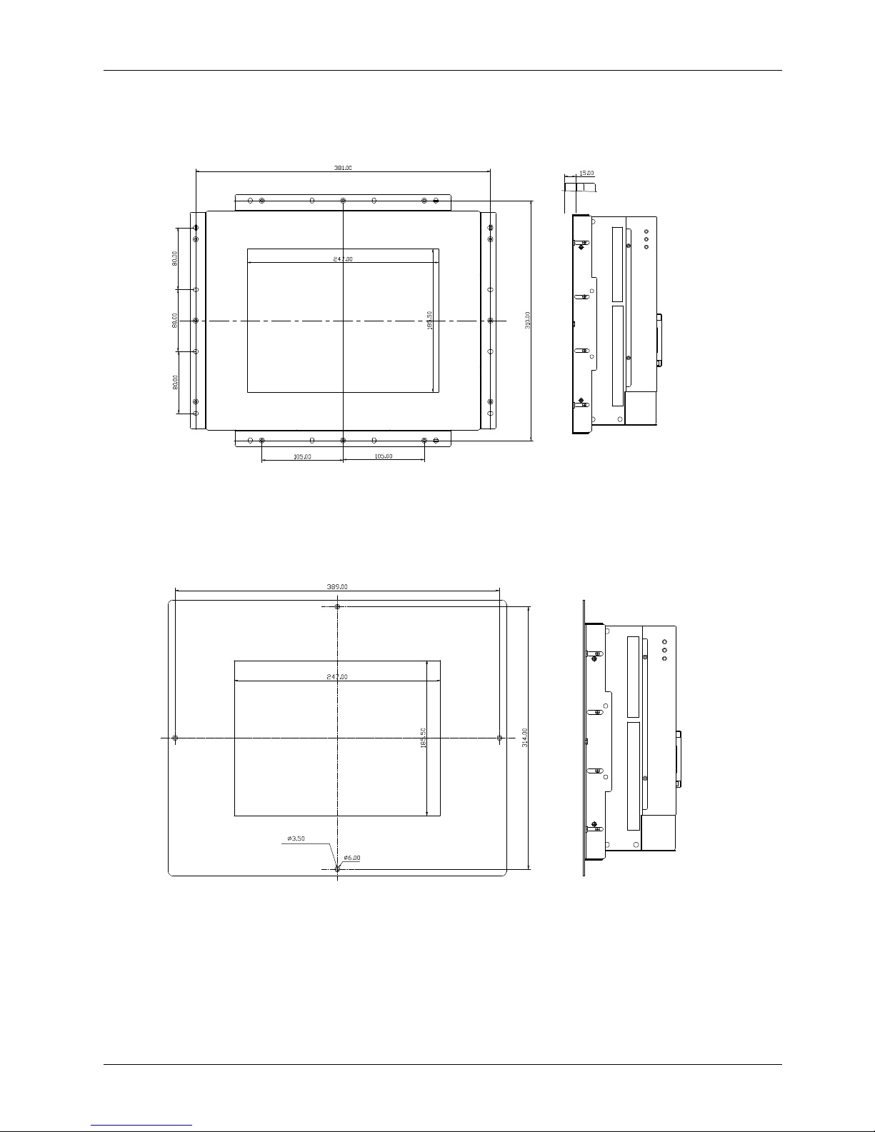
3.2.1.
OP 1200
Panel Mount
The followin
g figures illustrate the distance between the screw holes on the bezel to be fixed with the
L-shape mounting brackets.
OP
1200
WITH SMALL BEZEL
4-
沙拉孔
OP
1200
WI
TH BIG BEZEL

Service
Manual ver
sion
1008
OP 1200/15
0
0/170
0
(PC920 Intel 945G)
3-21
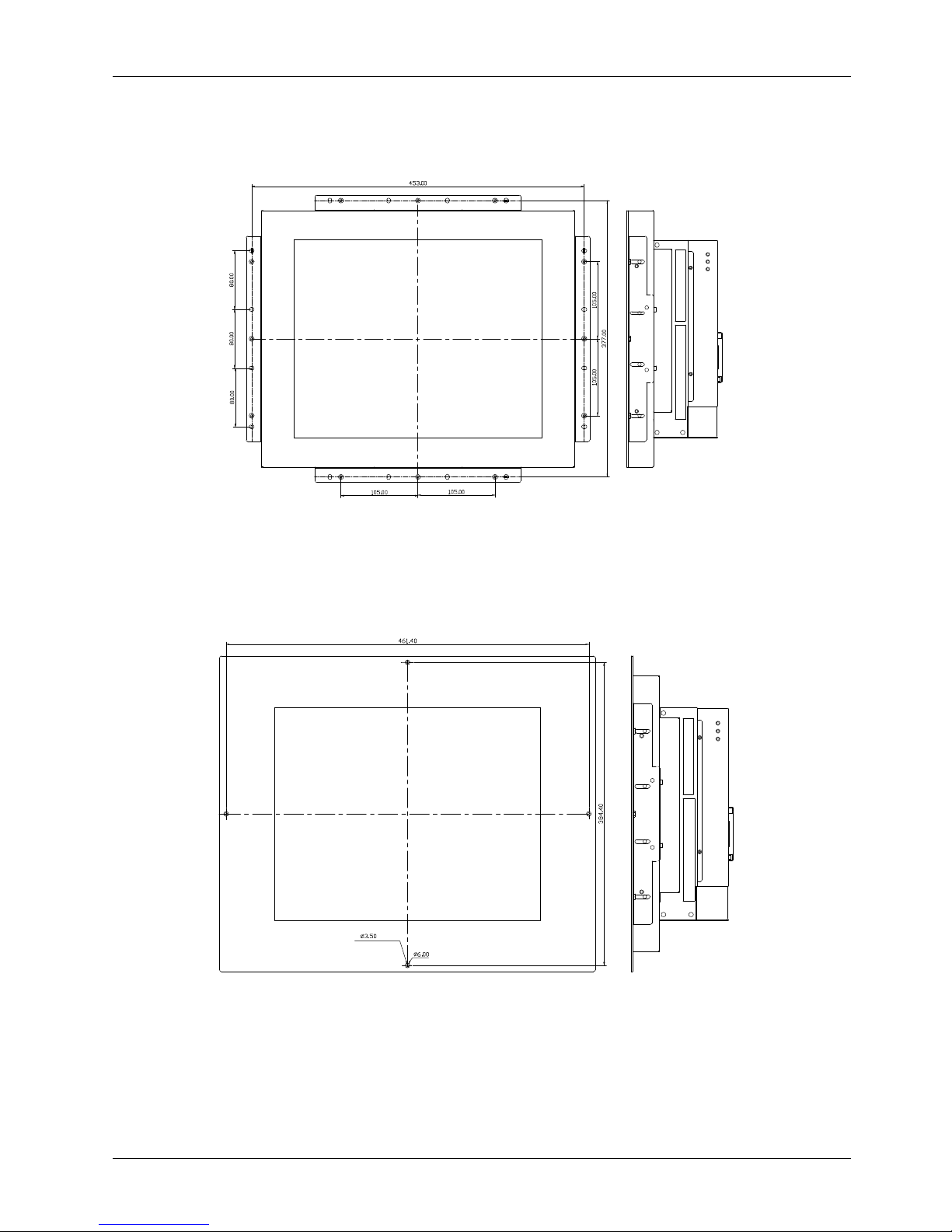
3.2.2.
OP 1500
Panel Mount
The following figures illustrate the distance between the screw holes on the bezel to be fixed wit
h the
L-shape mounting brackets.
OP
1500
WITH SMALL BEZEL
OP
1500
WITH BIG BEZEL
4-
沙拉孔
Service
Manual version
1008
OP 1200/15
0
0/170
0
(PC920 Intel 945G)
3-22
3.2.3.
OP 1700
Panel Mount
The following figures illustrate the distance between the screw holes on the bezel to be fixed with the
L-shape mounting brackets.
OP
1700
WITH SMALL BEZEL
OP
1700
WITH BIG BEZEL
4-
沙拉孔
 Loading...