

Page 1
12.1” /15
”
Intel C
ore 2 Duo
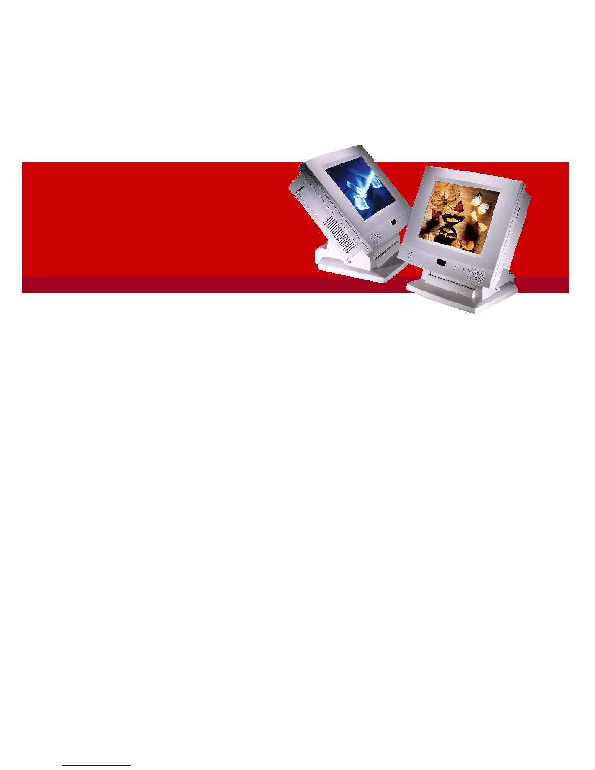
Multimedia panel PC with Versatile Stand Design
Panel PC
MP1200/M
P1500
(
MB:PC920,System Chipset:
Intel
945
G
)
Service
Manual
(Version
2807
)
Version v2911, November 2009
Version v
1008
,
August
2
010
Page 2

Copyright Notice
This publication, including all photographs, illustrations and software, is protected under
international copyright laws
, with all rights reserved. Neither this manual, nor any of the material
contained herein, may be reproduced
without written consent of the
m
anufacturer.
Disclaimer
The information in this document is subject to change without notice. The manufacturer ma
kes no
representations or warranties with respect to the contents hereof and specifically disclaims any
implied warranties of merchantability or fitness for any particular purpose. The manufacturer
reserves the right to revise this publication and to make
changes from time to time in the content
hereof without obligation to notify any person of such revision or changes.
Trademarks
All brand
s
and product names used for identification in this document are trademarks or registered
trademarks of their respecti
ve companies.
Federal Communications Commission (FCC)
This equipment has been tested and found to comply with the limits for a Class A digital device,
pursuant to Part 15 of the FCC Rules. These limits are designed to provide reasonable protection
against
harmful interference in a residential installation. This equipment generates, uses, and can
radiate radio frequency energy and, if not installed and used in accordance with the instructions,
may cause harmful interference to radio communications. However,
there is no guarantee that
interference will not occur in a particular installation. If this equipment does cause harmful
interference to radio or television reception, which can be determined by turning the equipment off
and on, the user is encouraged to
try to correct the interference by one or more of the following
measures:
Reorient or relocate the receiving antenna.
Increase the separation between the equipment and the receiver.
Connect the equipment onto an outlet on a circuit different from that to
which the receiver
is connected.
Consult the dealer or an experienced radio/TV technician for help.
Shielded interconnect cables and a shielded AC power cable must be employed with this equipment
to ensure compliance with the pertinent RF emission limits g
overning this device. Changes or
modifications not expressly approved by the system's manufacturer could void the user's authority
to operate the equipment.
Declaration of conformity
This device complies with part 15 of the FCC rules. Operation is subject
to the following conditions:
This device may not cause harmful interference, and
This device must accept any interference received, including interference that may cause
undesired
operation
© Copyright 200
8 July
Version
2
807
All rights reserved.
Printed i
n Taiwan
Page 3

Unpacking
U
npacking the carton
s,you will see the
panel PC
cabinets packed in separate cartons.
Remove all
the EPE foams stuffed in the cartons and the
panel PC
cabinets. These packing materials are used
to protect the components from swinging
around
d
uring local transpor
t
ation. It is strongly
recommended
thatthey are kept for future transportation use.
C
heck and see if the following items
are included and in good condition.
MP1200/MP1500
unit
Pedestal set
Accessor
y box
-
Power cord
(90o)
x 1
-
Base knob with rubber
bumper
x 1-Utilities
,
drivers & user manual CD diskette
x 1
Make sure that all of the items listed above are present. If any of the above items is missing, contact
your dealer immediately.
Warranty
All product
s
pro
duced
by
themanufacturer
are warranted against defective materials and
workmanship for one year starting from the date of delivery to the original purchaser.
However, this warranty does not apply to: (1) damage caused by accident, abuse, misuse,
misappli
cation, (2) the product or part has been modified, (3) the product serial number or
warranty label has been removed or defaced.
Page 4

Important Safety Precautions
Before getting started, read these instructions and save them for later reference.
1.
To access any
internal components of the system
, confirm the s
ystem
power is
turned
off
and make sure all the
system
fans already stop turning.
2.
Turn off the computer before cleaning. Clean with a damp or dry cloth only.
Do not spray
any liquid cleaner on screen
.3.The
power socket used to plug in the power cord must be located near the system and
easily accessible. Do not use outlets on the same circuit of the systems that regularly
switched on
and
off.4.Make sure the voltage of the power source is correct before connec
ting the system to the
power outlet.
5.
If the
system
is sharing an extension cord with other devices, make sure the total ampere
rating of the devices plugged into the extension cord does not exceed the cord
’
s ampere
rating.
6.
Do not expose the power cord, p
ower outlet
and exte
nsion cord to moisture.
7.
Install the
system
on a reliable surface to prevent damage caused by dropping.
8.
Disconnect the power cord from the system before any installation. Make sure both the
system and the external devices are turned off.
The sudden surge of power may ruin any
sensitive components. Also make sure the system is properly grounded.
9.
During installation of any internal components, be sure to ground yourself to keep from
any static charge. Most electronic components are sensi
tive to the static electric charge.
Use a grounding wrist strap and place all electronic components in any static
-
shielded
devices.
10.
The openings on the system cabinet are for the cabin ventilation to prevent the system
from overheating.
DO NOT COVER THE O
PENINGS
.
11.
The brightness of the flat panel display will decrease with use. However, hours of use will
vary depending on the application environment.
12.
Avoid
using sharp objects to operate the touch panel. Scratches on the touch panel may
cause mal
-calibra
t
ion or non
-
function to the
touch
panel.
13.
The LCD panel display is not subject to shock or vibration. When assembling the computer,
make sure it is securely installed.
Page 5

Table of Contents
1.
INTROD
UCTION
................................
................................
................................
................................
..............
1-1
1.1.
G
ENERAL
I
NFORMATION
................................
................................
................................
................................
.1-21.2.
W
HATCOVERS IN THIS
M
ANUAL
................................
................................
................................
....................
1-3
1.3.
S
PECIFICATIONS
................................
................................
................................
................................
.............
1-42.USINGTHE SYSTEM
................................
................................
................................
................................
.......2-62.1.
I
NTEGRATING THE PANEL
PC
................................
................................
................................
..........................
2-7
2.2.
I
DENTIFYING THE
S
YSTEM
................................
................................
................................
..............................
2-8
2.2.1.
Front View
................................
................................
................................
................................
.............
2-8
2.2.2.
Side Views
................................
................................
................................
................................
.............
2-8
2.3.
P
ANEL
PC
I/O
O
UTLETS
................................
................................
................................
................................
.2-92.4.
MP1200/MP1500
D
IMENSION
................................
................................
................................
......................
2-11
2.4.1.
MP1200
................................
................................
................................
Error!Bookmark not defined.
2-11
2.4.2.
MP1500
................................
................................
................................
Error!Bookmark not defined.
2-11
2.5.
P
OWERING UP THE
S
YSTEM
................................
................................
................................
...........................
2-12
2.6.
R
UNNING TH
E
BIOS
S
ETUP
................................
................................
................................
...........................
2-13
2.7.
O
PERATING
S
YSTEM AND
D
RIVER
I
NSTALLATION
................................
................................
...........................
2-133.VERSATILE STANDING &
MOUNTINGOPTIONS
................................
................................
.....................
3-14
3.1.
V
ERSATILE
S
TAND
................................
................................
................................
................................
........3-153.1.1.
Standing Upright
................................
................................
................................
................................
..3-153.1.2.
45 to 90
0
Free
Standing
................................
................................
................................
.........................
3-15
3.1.3.
Fixed Standing
................................
................................
................................
................................
......3-163.1.4.
Cable Management
................................
................................
................................
...............................
3-17
3.2.
W
ALLMOUNTING AND
M
OBILE
A
PPLICATIONS
................................
................................
...............................
3-18
3.3.
P
ANELMOUNTING
................................
................................
................................
................................
........3-193.4.
K
IOSKINTEGRATION
................................
................................
................................
................................
.....3-204.
KNOCKINGDOWN THE PA
NELPC
................................
................................
................................
.............
4-21
4.1.
D
ETACHING THE
P
EDESTAL
................................
................................
................................
...........................
4-22
4.2.
D
ISASSEMBLIN
G THE
P
ANEL
PC
................................
................................
................................
.....................
4-23
4.2.1.
Disassembling the Display Module
................................
................................
................................
.......4-244.2.2.
Knocking down the panel PC’s Individual Modules
................................
................................
...............
4-25
4.2.2.1.
Disassembling the PC I/O Module
................................
................................
................................
....................
4-25
4.2.2.2.
Disassembling the Riser CardModule
................................
................................
................................
...............
4-26
4.2.2.3.
Disassembling the Power SupplyModule
................................
................................
................................
..........
4-26
4.2.2.4.
Detaching the slim CD
-
R/FDD
................................
................................
................................
.........................
4-27
4.2.2
.5.
Disassembling the Expansion Door
................................
................................
................................
...................
4-27
4.2.2.6.
Detaching the HDD
................................
................................
................................
................................
..........
4-28
4.2.2.7.
Detaching the Touchscreen Controller
................................
................................
................................
...............
4-28
4.2.2.8.
Removing CPU & DDR
................................
................................
................................
................................
...4-
29
5.
BUILDINGUPTHEPANE
LPC
................................
................................
................................
.......................
5-305.1.
D
ISPLAY
M
ODULE
A
SSEMBLY
................................
................................
................................
........................
5-33
5.1.1.
Front Bezel Assembly
................................
................................
................................
............................
5-33
5.1.2.
LCD Module Assembly
................................
................................
................................
.........................
5-34
5.1.2.1.
MP1200
LCD Assembly
................................
................................
................................
................................
...5-345.1.2.2.
MP1500
LCD assembly
................................
................................
................................
................................
....5-
35
5.1.3.
Display Module Inte
gration
................................
................................
................................
..................
5-36
5.2.PCM
ODULE
A
SSEMBLY
................................
................................
................................
................................
5-37
5.2.1.
Motherboard Assembly
................................
................................
................................
.........................
5-38
5.2.1.1.
Installing the CPU
................................
................................
................................
................................
............
5-38
5.2.1.2.
Installing the DDR Memory Module
................................
................................
................................
.................
5-39
5.2.2.
Touchscreen ControllerAssembl
y
................................
................................
................................
..........
5-40
5.2.3.
HDD Module Assembly
................................
................................
................................
.........................
5-40
5.2.4.
Power Module Assembly
................................
................................
................................
.......................
5-41
5.2.5.
FDD/CD
-
ROM Assembly
................................
................................
................................
......................
5-42
Page 6

5.2.6.
Expansion Door Assembly
................................
................................
................................
....................
5-43
5.2.7.
Riser Card Assembly
................................
................................
................................
.............................
5-43
5.2.8.
I/O ModuleAssembly
................................
................................
................................
............................
5-44
5.2.9.
PC Module Integration
................................
................................
................................
.........................
5-45
5.2.9.1.
Motherbo
ard Integration
................................
................................
................................
................................
...5-455.2.9.2.
HDD Module Integration
................................
................................
................................
................................
..5-455.2.9.3.
Touchscreen Controller Integration
................................
................................
................................
...................
5-45
5.2.9.4.
ExpansionDoor Integration
................................
................................
................................
..............................
5-45
5.2.9.5.
Display Module Integration
................................
................................
................................
..............................
5-46
5.2
.9.6.
Slim CD
-
R/FDD Integration
................................
................................
................................
.............................
5-46
5.2.9.7.
Power Supply Integration
................................
................................
................................
................................
..5-475.2.9.8.
Riser Card Integration
................................
................................
................................
................................
.......5-475.2.9.9.
I/O Cover Integration
................................
................................
................................
................................
........5-475.2.9.10.
I/O Cover Integration
................................
................................
................................
................................
...5-475.2.9.
11.
Plastic Cover Integration
................................
................................
................................
..............................
5-47
5.3.
P
ANEL
PC
I
NTEGRATION
................................
................................
................................
................................
5-486.SYSTEM MOTHERBOARD&
I/O BOARDS
................................
................................
................................
.6-496.1.
MP1200/MP1500
M
OTHERBOARD
................................
................................
................................
...............
6-50
6.1.1.
General Information
................................
................................
................................
.............................
6-50
6.1.2.
Locating J
umpers & Connectors
................................
................................
................................
...........
6-51
6.1.3.
How to Set Jumpers
................................
................................
................................
..............................
6-52
6.1.4.
Jumpers & Jumper Setting
................................
................................
................................
....................
6-53
6.1.4.1.
Clear CMOS (JP3)
................................
................................
................................
................................
............
6-53
6.1.5.
Connectors & Pin Assignment
................................
................................
................................
...............
6-54
6.1.5.1.
ATXP1: ATX Power Co
nnector
................................
................................
................................
.........................
6-55
6.1.5.2.
ATXP2: ATX +12V Power Connector
................................
................................
................................
...............
6-55
6.1.5.3.
CN1: TouchscreenPower Connector
................................
................................
................................
.................
6-55
6.1.5.4.
PWR1: Power Output Connector
................................
................................
................................
.......................
6-55
6.1.5.5.
INV1: LCD Inverter Connector
................................
................................
................................
.........................
6-55
6.1.5.6.
USB1,2: USB Port Connector
................................
................................
................................
...........................
6-56
6.1.5.7.
LCD1: LCD Connector
................................
................................
................................
................................
.....6-566.1.5.8.
IDE1: PATAConnector for CD
-
ROM
................................
................................
................................
................
6-57
6.1.5.9.
SATA1~4 : SATAConnector
................................
................................
................................
.............................
6-57
6.1.5.10.
COM2
................................
................................
................................
................................
..........................
6-58
6.1.5.11.
COM3................................
................................
................................
................................
..........................
6-58
6.1.5.12.
CD1: CDAudio IN
................................
................................
................................
................................
......6-586.1.5.13.
IR: IR/CIR Connector
................................
................................
................................
................................
...6-586.1.5.14.
CN4: Power LED & EXT. KB/MS, USB
................................
................................
................................
.......6-596.1.5.15.
IOINF 1: I/O Connector
................................
................................
................................
................................
6-59
6.1.5.16.
EISA1: PCI/ISAExpa
nsion Slot
................................
................................
................................
...................
6-60
6.1.5.17.
FAN 1~3: FAN Connector
................................
................................
................................
............................
6-62
6.1.5.18.
CN3: ATX Power on Switch
................................
................................
................................
.........................
6-62
6.1.5.19.
RST1: Reset System Connector
................................
................................
................................
....................
6-62
6.1.5.20.
CN2: External LAN Wake
-up................................
................................
................................
.......................
6-62
6.2.
MP1200/M
P1500
I/O
B
OARDS
................................
................................
................................
.....................
6-63
6.2.1.
I/O Board IO
-
005
................................
................................
................................
................................
.6-
64
6.2.1.1.
Jumpers & Jumper Setting
................................
................................
................................
................................
6-64
6.2.1.2.
CN4: EXT. Connector
................................
................................
................................
................................
......6-
64
6.2.2.
IO Board
-
IO006
................................
................................
................................
................................
...6-
65
6.2.2.1.
Jumpers & Jumper Setting
................................
................................
................................
................................
6-65
6.2.2.2.
CN6: EXT. Connector
................................
................................
................................
................................
......6-
65
6.2.3.
Connectors & Pin Assignment
................................
................................
................................
...............
6-67
6.2.3.1.
Keyboard: PS/2 KB Connector
................................
................................
................................
.........................
6-68
6.2.3.2.
Mouse: PS/2 Mouse
................................
................................
................................
................................
..........
6-68
6.2.3.3.
COM1, COM2, COM4 (DB
-9)................................
................................
................................
.........................
6-68
6.2.3.4.
DC Power: DC Power Output
................................
................................
................................
..........................
6-68
6.2.3.5.
LPT1: D
-
SUB-25 Parallel Port
................................
................................
................................
..........................
6-68
6.2.3.6.
CRT: VGA(D
-
SUB 15 Pin)
................................
................................
................................
..............................
6-69
6.2.3.7.
FDD: External FDD Connector
................................
................................
................................
.........................
6-69
Page 7

6.2.3.8.
J11: USB 1, USB2 Connector
................................
................................
................................
..........................
6-69
6.2.3.9.
DIO1: RJ
-
11 Connector
................................
................................
................................
................................
....6-696.2.3.10.
LAN1: RJ
-
45 Ethernet Connector
................................
................................
................................
.................
6-69
6.2.3.11.
MIC1
................................
................................
................................
................................
...........................
6-69
6.2.3.12.
LINE 1
................................
................................
................................
................................
.........................
6-70
6.2.3.13.
SPK 1
................................
................................
................................
................................
..........................
6-70
7.
BIOS SETUP UTILITY
................................
................................
................................
................................
.....7-727.1.
A
BOUT THE
BIOS
S
ETUPUTILITY
................................
................................
................................
..................
7-73
7.2.
C
ONTROL
KEYD
EFINITION
................................
................................
................................
...........................
7-74
7.3.
G
ETTING
H
ELP
................................
................................
................................
................................
.............
7-75
7.3.1.
Main Menu
................................
................................
................................
................................
...........
7-75
7.4.
AWARD
BIOS
S
ETUP
................................
................................
................................
................................
...7-757.4.1.
Entering the Setup Utility
................................
................................
................................
......................
7-75
7.4.2.
Standard CMOS Features
................................
................................
................................
.....................
7-77
7.4.3.
Advanced BIOS Features
................................
................................
................................
......................
7-80
7.4.4.
Advanced Chipset Features
................................
................................
................................
...................
7-83
7.4.5.
Integrated Peripherals
................................
................................
................................
..........................
7-85
7.4.5.1.
OnChip IDE Device
................................
................................
................................
................................
.........
7-86
7.4.5.2.
OnChip Device
................................
................................
................................
................................
.................
7-88
7.4.5.3.
Sup
erIO Device
................................
................................
................................
................................
................
7-89
7.4.6.
Power Management Setup
................................
................................
................................
....................
7-91
7.4.7.
PnP/PCI Configuration
................................
................................
................................
........................
7-93
7.4.8.
PC Health Status
................................
................................
................................
................................
..7-
95
7.4.9.
Frequency VoltageControl
................................
................................
................................
....................
7-96
7.4.10.
Load Fail
-
Safe Defaults
................................
................................
................................
........................
7-96
7.4.11.
Load Optimized Defaults
................................
................................
................................
......................
7-98
7.4.12.
User Password
................................
................................
................................
................................
.....7-98EN
TER PASSWORD
................................
................................
................................
................................
................
7-98
CONFIRM PASSWORD
................................
................................
................................
................................
...........
7-98
7.4.13.
Save and Exit Setup
................................
................................
................................
..............................
7-99
7.4.14.
Exit Without Saving
................................
................................
................................
..............................
7-998.SOFTWARE & DRIVERS I
NSTALLATION
................................
................................
................................
.8-
1008.INSTALLINGDRIVERSA
ND SOFTWARE
................................
................................
................................
.8-
101
8.1.
C
HIPSET
................................
................................
................................
................................
....................
8-101
8.2.
LAN
DRIVERS
................................
................................
................................
................................
............
8-101
8.3.
A
UDIO DRIVERS
................................
................................
................................
................................
.........
8-101
8.4.
VGA
DRIVERS
................................
................................
................................
................................
...........
8-101
8.5.
T
OUCH SCREEN DRIVERS
................................
................................
................................
...........................
8-101
8.5.1.
Taiwan bra
nd Resistive Touch conrtoller :
................................
................................
.........................
8-101
8.5.2.
Elo Resistive & SAW Touch conrtoller :
................................
................................
.............................
8-102
8.6.
O
PTION DRIVER
................................
................................
................................
................................
.........
8-102
Page 8

Page 9

Service
Manual version
1008
MP1200/MP1500
(PC920 Intel 945G)
1-1
11..IInnttrroodduuccttiioon
n
This chapter provides background information and
detail specification on the
MP1200/MP1500
.
Sections in this chapter include:
General Information
What covers in this Manual
Specification
Dimension
Page 10

Service
Manual version
1008
MP1200/MP1500
(PC920 Intel 945G)
1-2
1.1.
General Information
The in
formation revolution
that
started from the mid '90s inaugurated a new competitive era
where consumer computing technology was exploited to do business operation quicker than ever
before. Many enterprises from life
-
related industries such as
Photo printing
,Ba
nking
,
Medical
to
POS
,
Kiosk
,
Security
,
Advertising
… etc. all are eager or forced to automate their industries
with computers in order to thrive in this new age.
For their industrial automation, there is one
thing in common, i.e. space is always a pre
mium and system stability is always a must in their
environmental applications.
The
MP1200/MP1500
is a 12.1"/15
" TFT
Intel Core 2 Duo
plastic
-
housing multimedia panel PC
system. Featuring with versatile stand design for different environmental applicatio
ns, the
MP1200/MP1500
itself can be used as a ready
-to-
play system by connecting to necessary
peripherals. It also provides one set of VESA holes for market
-
available swing arms for mobile
application.
In terms of panel size, the
MP1200/MP1500
has 12.1”
an
d 15
” systems. In terms of system
engine, the
MP1200/MP1500
has
four
versions,
one
MP1200/MP1500
Intel Core 2 Duo
system
.
To upgrade the system, simply replace the Motherboard
and the power supply
.
Fully configurable and with its sleek outlook, the
MP1
200/MP1500
is an ideal platform for any
space
-
constricted application.
Page 11

Service
Manual version
1008
MP1200/MP1500
(PC920 Intel 945G)
1-3
1.2.
What Covers in this Manual
Thisservice manual provides service information for the
MP1200/MP1500
panel PC
.
This manual is
designed to help trained service personnel to locate and fi
x failing parts on the
MP1200/MP1500
.
Only
service technicians are allowed to open the system for service
.
You do not need to read everything in
this handbook to
service
the system.
For a quick start, see the following chapter summaries;
Chapter 1
(the c
urrent chapter) provides background information and detail specification on the
MP1200/MP1500
.
Chapter 2
identifies the
MP1200/MP1500
system exterior components and provides instructions to
help you to use the system as soon as possible.
Chapter 3
details
the panel PC’s various standing and mounting options by graphical illustrations.
Chapter
4
helps you to
knock down the
system
into parts
to access components
.
Chapter
5
helps you to
build up the panel PC
.
Chapter
6
provides detail information of the jump
er settings and connector signals of the system
control board
and I/O boards
.
Chapter
7
explains the AWARD BIOS setup.
Chapter
8
introduces the Ethernet, XGA
, audio
and
touchscreen
drivers.
Appendix A
introduces
the
built
-inLCD.
Appendix B
introduces the
system
’
s onboard DIO.
Appendix
C
introduces the Wake
-On-
LAN feature.
Appendix
D
describes the system IO port address
Appendix
E
explains the first MB memory map.
Appendix
F
provides the specifications for the built
-
in power supply.
Page 12

Service
Manual version
1008
MP1200/MP1500
(PC920 Intel 945G)
1-4
1.3.
Specifications
MP1200/M
P1500
:
12.1”
/15
” TFT Intel
®
Core 2 Duo
p
lastic
-
housing panel PC with
Versatile
Stand
design
CPU
:
Intel
Celer
on 2.0 GHz up to Core 2 Duo 2.6
GHz
Motherboard
:PC920System Chipset
: Intel
945G&
ICH7
System BIOS
:
Award PnP Flash BIOS
System Memory
: 2x240pin DDR
2to4GBDisplay Module
12.1" TFT LCD, 800 x 600
15" TFT LCD, 1024 x 768
Supports Dynamic Video Memory Technology(DVMT)
Standard I/Os
Serial ports x 4: COM 1, 2 & 4 with +5V/12 power output on pin #9, COM 3 internal type
reserved for touchscreen,
COM2 RS
-
232/485 jumper selectable
Parallel
p
ort x 1: supports SPP/EPP/ECP
External FDD
i
nterface x 1
+5V/+12V DC
-
out x 1
PS/2
k
eyboard
i
nterface x 1
PS/2
m
ouse
i
nterface x 1
DIO: Input x 2, output x 2
USB
i
nterface x 2
VGA
i
nterface x 1
Brightness VR x 1
Audio
Speaker
x 2Speaker
-
out,
line-in &
MIC-inEtherne
t100/10 Base
-
T PnP Ethernet with RJ
-45Support
sWake-on-LANExpansion Slot
PCI*2
Front Bezel
LED indicators for HDD, LAN, POWER
Audio Function
Full duplex and independent sample rate converter for
audio recording & playback
Supports Microsoft DirectSound
3D positional audio effects
Hi-
performance, mixed
-
signal stereo
MIC-In,speaker
-out,line-In
Pin header for CD
-
audio in
Hardware Monitor
Monitor
s
processor & system
temperature
Monitor
s
5VSB, VBA
T, 1.5V, 3.3V, +5V,
+12V
and processor voltages
Monitors processor
and
chassis fan speeds
Control
s
processor
,
chassis fan speed and failure alarm
Automatic fan on/off control
Read
-
back capability that displays temperature, voltage and fan speed
Page 13

Service
Manual version
1008
MP1200/MP1500
(PC920 Intel 945G)
1-5Support
sIntel processor thermal diode output (real processor temperature)
Power Supply
:
250W,
100~240V/
5~3A,
@
50~
60Hz
Touchscreen
(optional, sharing COM3)
12.1”
/15
” analog resistive type with RS
-
232 controller
15” surface acoustic wave type (SAW)
Drive Bay
3.5"HDD
SATA Interface
Slim
CD-ROM or equivalent device
MECHANICAL & ENVIRONMENTAL
Construction
Inside: Heavy
-
duty steel
Outside:
F
ire-proof resilient ABS/PC plastic
Color
(standard)
Beige
Charcoal
Dimension
(chassis only, unit: mm)
MP1200
: 368*321*116.5 (L*W
*D); 334.7*284.21 (for panel mount)
AO1500: 406*360*129 (L*W*D); 384*284.2 (for panel mount)
Mounting
Panel mount with mounting kits
(optional)
Wall mount with swing arm: standard VESA mounting holes (75*75 mm)
Versatile Stand
45~9
0
°
free standing
Avocado
-
shape holes for fixed standing
Cable Management design
Specifications are subject to change without notice.
Page 14

Service
Manual version
1008
MP1200/MP1500
(PC920 Intel 945G)
2-6
22..UUssiinnggtthheeSSyysstteem
m
Integrating the
panel PC
Identifying the
System
Panel PC
I/O outlets
Panel PC
dimension
Powering up the System
Running the BIOS
Setup
Operating System & Driver Installation
Page 15
Service
Manual version
1008
MP1200/MP1500
(PC920 Intel 945G)
2-7
Pedestal
Base upper cover
PMS 4*18 (4)
PMS 3*6 (2)
2.1.
Integrating the
panel PC
The
MP1200/MP1500
p
anel PC
is mainly composed of
two
parts: the
p
anel PC
and the
pedestal
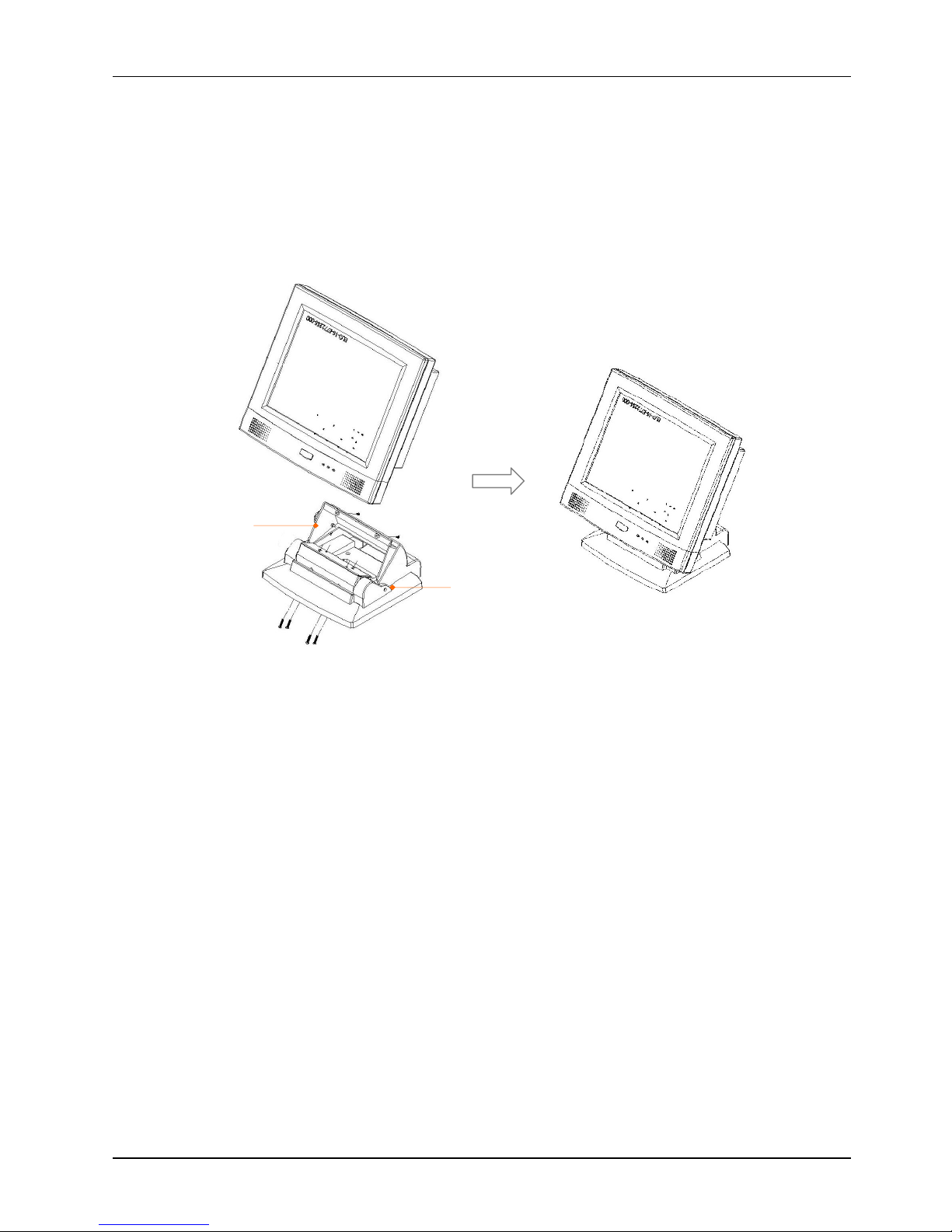
.1.Obtain a base knob
(1)
from the accessory box.
2.
Retain the
plastic upper cover
(2)
to the
ba
se module
with the
base knob
(1).3.
There are two
rectangle
opening
s at the bottom side of the pedestal. Insert a long driver into the
openings and retain the base hinges to the
pane PC
four PMS M4*18 screws.
4.Re
tain the plastic upper cover to the panel PC
with two PMS M3*6 screws.
The stand can be tilted from
45 to 90
o
by
swiveling the
base
knob and pulling the base up and down
.
2.2.
Page 16
Service
Manual version
1008
MP1200/MP1500
(PC920 Intel 945G)
2-8
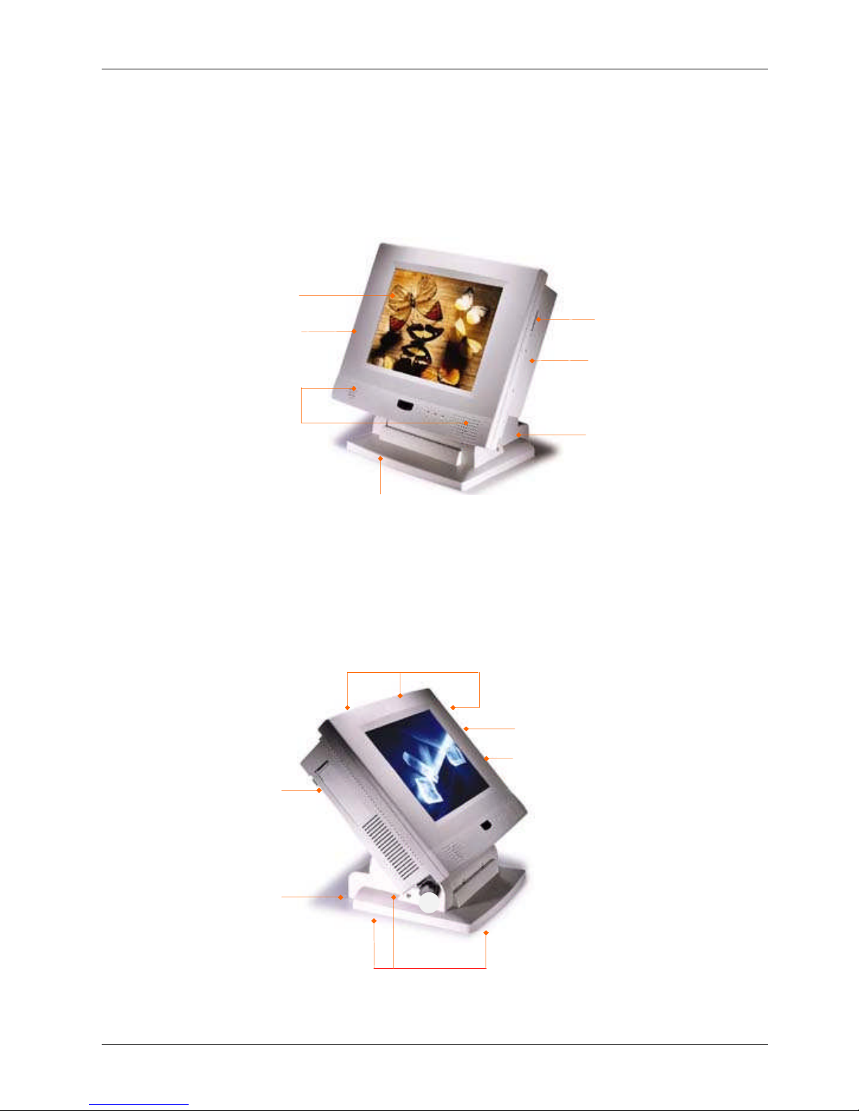
FDD drive &
CD-ROM drive
Versatile stand for
desktop standing
12.1”/ 15” LCD &
touchscreen
Fire-proof
resilient plastic
Side door for two
PCI
expansion outlet
Cable management
covers
Speaker
Identifying the System
Before getting started, take a moment to familiarize yourself with the system and the I/O
arran
gement of the
MP1200/MP1500
.
2.2.1.
Front View
When the
MP1200/MP1500
is put upright on the desktop with the provided pedestal, its front view
appears as below.
The illustrations of the
MP1200/MP1500
may differ slightly because the
this
series has two different
LCD size: 12.1”
& 15
”.
2.2.2.
Side Views
The left side of the panel PC appears as below:
Side door for two PCI expansion
outlet
Cabling outlet
Floppy disk drive
CD-ROM
Base covers +
pedestal = versatile stand
Screw holes for peripheral device attachment
Page 17
Service
Manual version
1008
MP1200/MP1500
(PC920 Intel 945G)
2-9
2.3.Panel PC
I/O Outlets
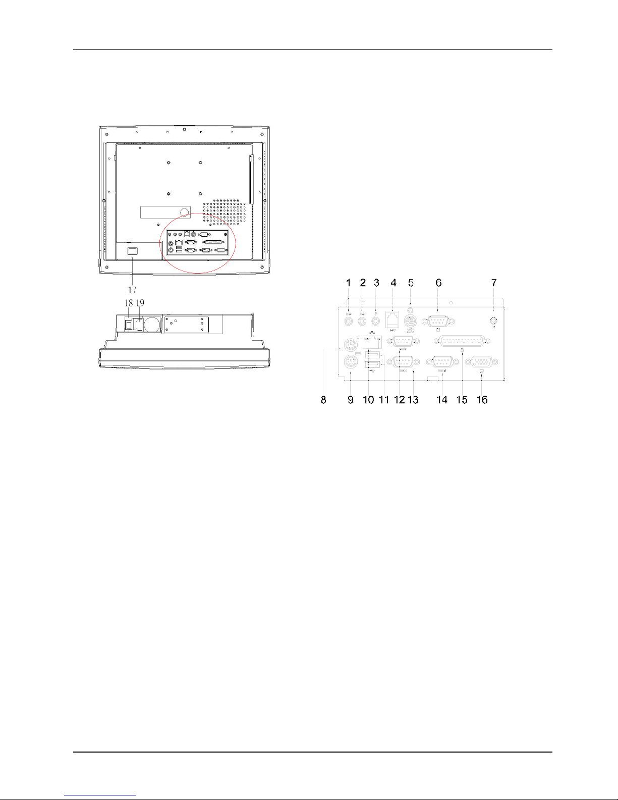
When you turn around the
MP1200/MP1500
system, you will find the power switch a
nd all the I/O
ports are located at the rear cover of the panel PC
.
1. Speaker
-
out
2. Line
-in3. MIC
-in4. 2-channel DIO
5. +5/12V DC
-
out
6. External FDD
7.
VR brightness
8.
PS/2 Mouse
9.
PS/2 Keyboa
rd
10.
Ethernet (RJ
-
45)
11.
USB*2
12.
COM 1
13.
COM
2
14.
COM
4
15.
Printer port
16.
VGA port
17.PPC power switch
18.
Power supply switch
19.
AC inlet
Page 18

Service
Manual version
1008
MP1200/MP1500
(PC920 Intel 945G)
2-10
1.
Speaker
-
out: This jack is to output the audio to external devices such as speakers or earphones.
2.
Line-in: This jack is used t
o input audio from an external audio device such as a CD player, tape
recorder or a radio.
3.
MIC-in: This jack is used to record sound or voice by connecting to an external microphone
.4.DIO: The system provides 2
-
channel digital input and output.
5.
+5V/12V DC
-out: The DC
-
out
can provide +5V/12 power source for peripheral devices such as
smart card reader and scanner.
6.
External FDD: This port is provided to connect to an external floppy disk drive. An optional FDD
cable is needed to connect a standard 3.5” FDD to
the system.
7.
VR brightness control: This knob is to control the brightness of the LCD screen.
8.
PS/2 Mouse: This port is for PS/2 mouse connection.
9.
PS/2 Keyboard: This port is for PS/2 keyboard connection
.
10.
Ethernet (RJ
-
45): The system provides a 100/10 Base
-
T Ethernet interface.
11.
USB*2: These two ports are for USB device connection.
12.
COM1: This port is for serial device connection.
13.
COM2: This port is for serial device connection.
14.
COM4: This port is for serial device connection.
15.
Printer Port: This port is pro
vided to connect to a parallel device.
16.
VGA port: This port is provided to connect to an analog monitor.
17.
System p
ower switch
18.
Power supply switch
19.
AC inlet
TheseI/O interfaces are used to connect external peripheral devices
.
Before
connecting any devices
to the
panel PC
, make sure the
system
and the peripheral devices are turned off.
If there are any
retaining screws on the device cables, make sure they are properly fastened to the secure bolts on the
sides of each port. You might need to install drivers
for the new devices.
Refer to the p
eripheral
devices
manual
s
for instruction to configure the operation environment to recognize the new attached
devices.
Page 19
Service
Manual version
1008
MP1200/MP1500
(PC920 Intel 945G)
2-11
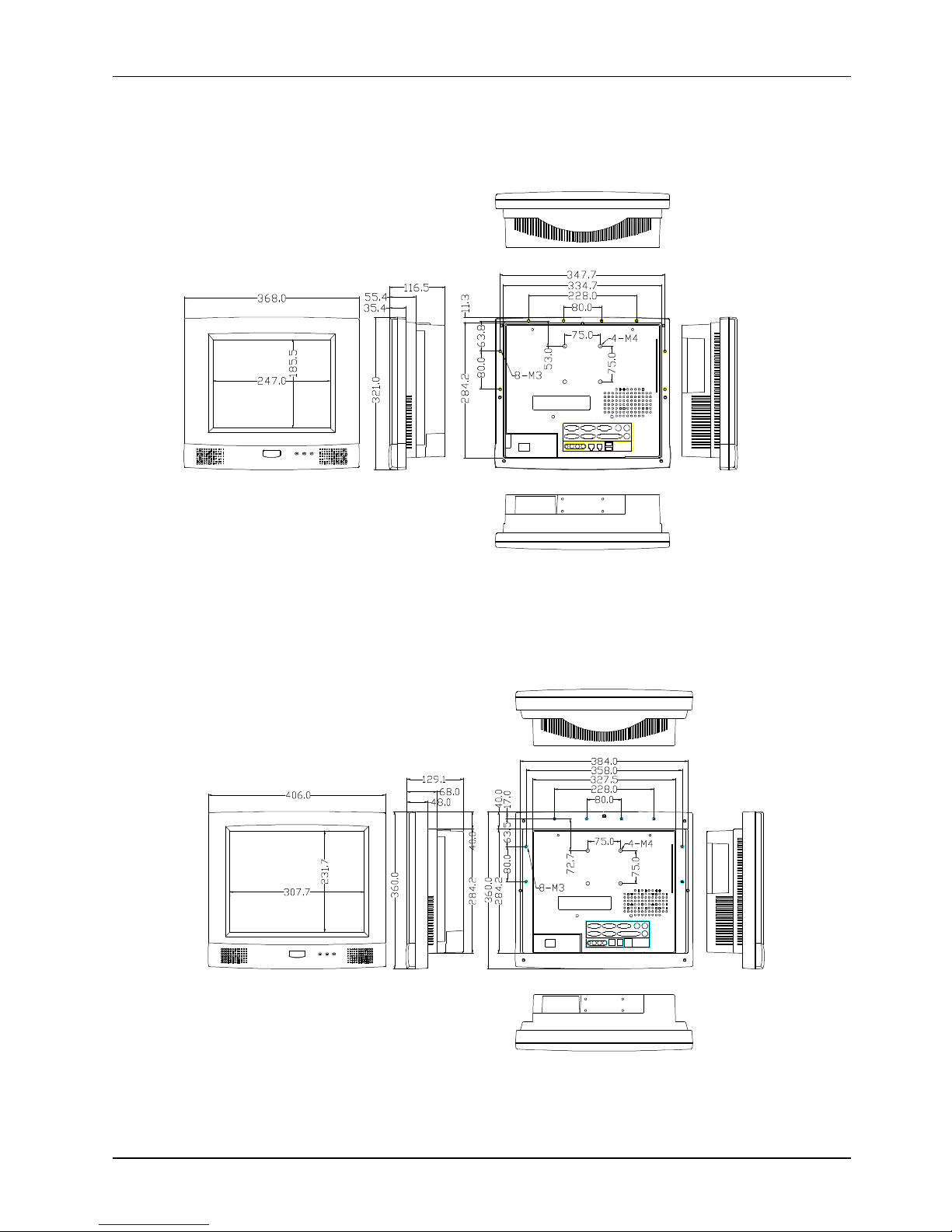
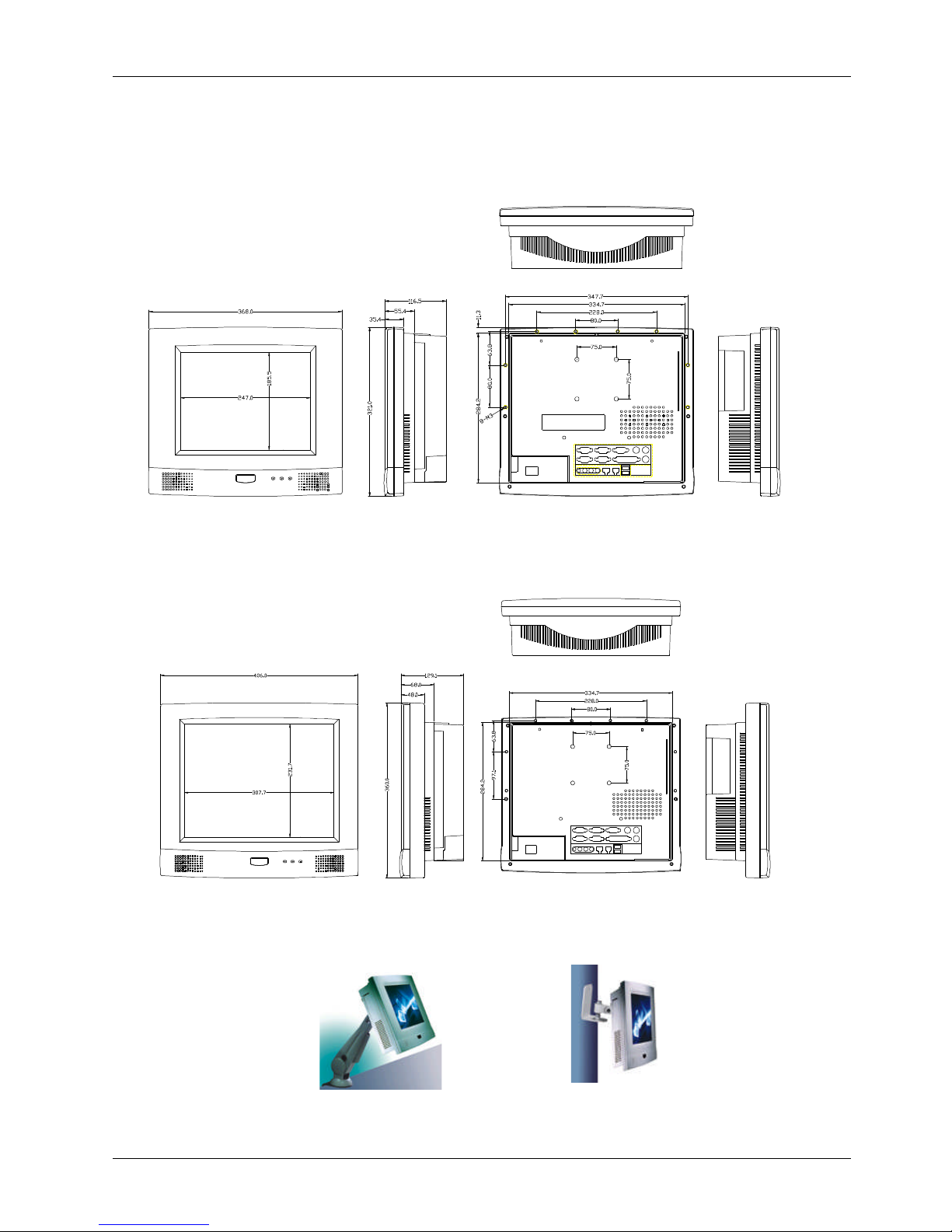
2.4.
MP1200/MP1500
Dimension
2.4.1.
MP1200
The
MP1200
’s chassis size is shown below. This does not include the d
imension of the stand.
2.4.2.
MP1500
TheMP1500
’s chassis size is shown below. This does not include the dimension of the stand.
MP1200
DIMENSION
OP1500
DIMENSION
Page 20
Service
Manual version
1008
MP1200/MP1500
(PC920 Intel 945G)
2-12
2.5.
Powering up the System
Upon receipt of the
MP1200/MP1500
, the system should have been properly
set up and
configured by your dealer.
To power up the system, follow the procedures below.
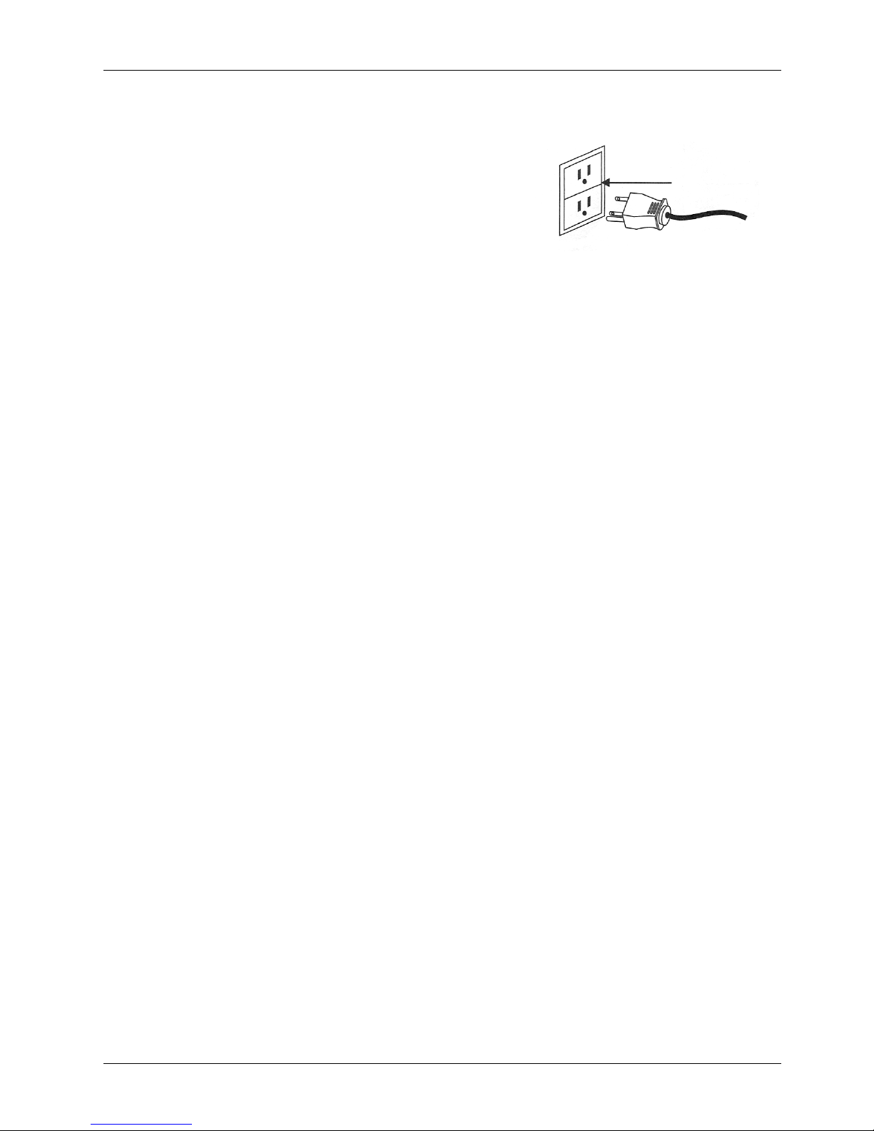
1.
Find the 90
o
power cord from the accessory box. Connect
the 3
-
pin female end of the power cord to the AC inlet
located at the
right rear lower side of
the pane
l
PC.
Plug
the 3
-
pin male end to an AC power socket.
2.
If there are any other peripheral devices connected to the
system, make sure all the device cables are properly
retained and
connected
to the panel I/O ports.
3.
Power on the external peripheral devices fi
rst.4.When facing the system, from your point of view, the power switch is at the right rear lower
side of the panel
PC
. Press the power switch.
Page 21

Service
Manual version
1008
MP1200/MP1500
(PC920 Intel 945G)
2-13
2.6.
Running the BIOS Setup
If you are a commercial user, the
MP1200/MP1500
system
should have been properly s
et up and
configured by your dealer. You may still find it necessary to change the system configuration
information. In this case, you need to run the system’s BIOS setup program.
Under the following conditions, the CMOS settings are to be changed.
1.
The
system is starting for the first time.
2.
The hardware devices attached to the
MP1200/MP1500
system have been changed.
3.
The CMOS memory has lost power and the configuration information has been erased.
The BIOS setup program is stored in ROM, which can be acce
ssed by pressing <DEL> key on the
keyboard immediately when the system is powered on.
In order to retain the specified setup information when the system power is turned off, the system
setup information is stored in a battery
-
backed CMOS RAM. The battery
is to ensure the settings will
not be erased when the computer is turned off or reset. When the computer is powered on again, the
system will read the settings stored in the CMOS RAM and compare them to the equipment check
conducted during the power on s
elf-test (POST). If any error or mismatch occurs, an error message
will be shown on the screen and the computer will be prompted to run the setup program.
To change the BIOS setup, please refer to
Chapter 7
for more information.
2.7.
Operating System and Dri
ver Installation
The
MP1200/MP1500
system is not equipped with an operating system when delivered from the
original manufacturer. If you are a commercial user, the system is likely to have been pre
-
installed
proper operating system and software drivers by
your dealer or system integrator.
If the system is not pre
-
installed with any system OS and drivers or you intend to install your
preferred ones, there are several ways to load OS and software into the system.
1.
Via
an USB data
-
retrieval devices
2.
Via the
CD-ROM
3.
Via Ethernet
Recent releases of operating systems always include setup programs that load automatically and
guide you through the installation. You can also refer to your OS user manual for instructions on
formatting or partitioning the hard disk d
rive before any software installation.
The
MP1200/MP1500
system provides the following utility drivers stored in the CD
-
ROM diskette or
utilities diskettes;
Ethernet utilities
VGA utilities
Audio drivers
Touchscreen drivers
Page 22

Service
Manual version
1008
MP1200/MP1500
(PC920 Intel 945G)
3-14
33..VVeerrssaattiilleeSSttaannddiinngg&&MMoouunnttiinnggOOppttiioonns
s
The
MP1200/MP1500
is designed for universal
standing and mounting to fit into various
environmental applications. This chapter highlights
the steps of different mounting options with graphical
illustrations. Sections include
Versatile Stand
Wall Mo
unting
Panel Mountin
gKiosk Integrating
Page 23
Service
Manual version
1008
MP1200/MP1500
(PC920 Intel 945G)
3-15
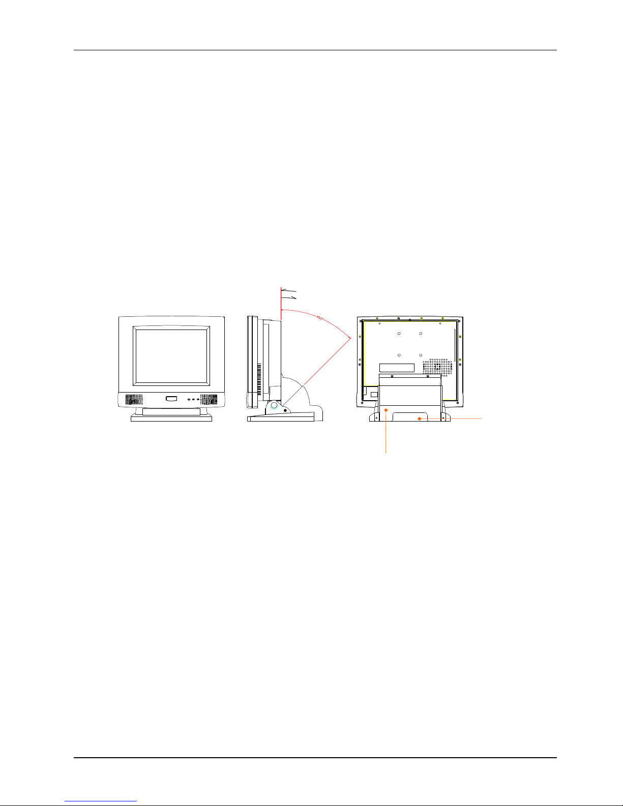
MP1200/MP1500
STANDING OPTIONS
Cable
management cover
Cable
outlet
3.1.
Versatile Stand
The
MP1200/MP1500
comes with a versatile and functional stand, able to fit into different
environmental application.
3.1.1.
Standing Upright
Compact in its size, all
-in-
one in its design along with its i
ndustrial
-
grade reliability, the
MP1200/MP1500
system standing upright is the best replacement f
or a desktop computer. When it
is
stand
ing
upright, the two
base back covers
canbeeither
integrated
or not
integrated
to the pedestal.
However, if the
MP12
00/MP1500
system is to
be used as a desktop system
while the touchscreen is
also frequently u
sed,it is suggested that the two
base back covers
and another knob are assembled
with t
he pedestal to prevent
the system from
wobbling when the touchscreen is bei
ng used.
3.1.2.
45 to 90
0
Free Standing
The sleek and sturdy pedestal assembled with the two cable covers enables the
MP1200/MP1500
system to endure the long
-
time operation in any public sectors. By swiveling the knob on the
pedestal and pulling the base up a
nd down, the angle can be
tilted
from 45 to 90
0
.
Page 24
Service
Manual version
1008
MP1200/MP1500
(PC920 Intel 945G)
3-16
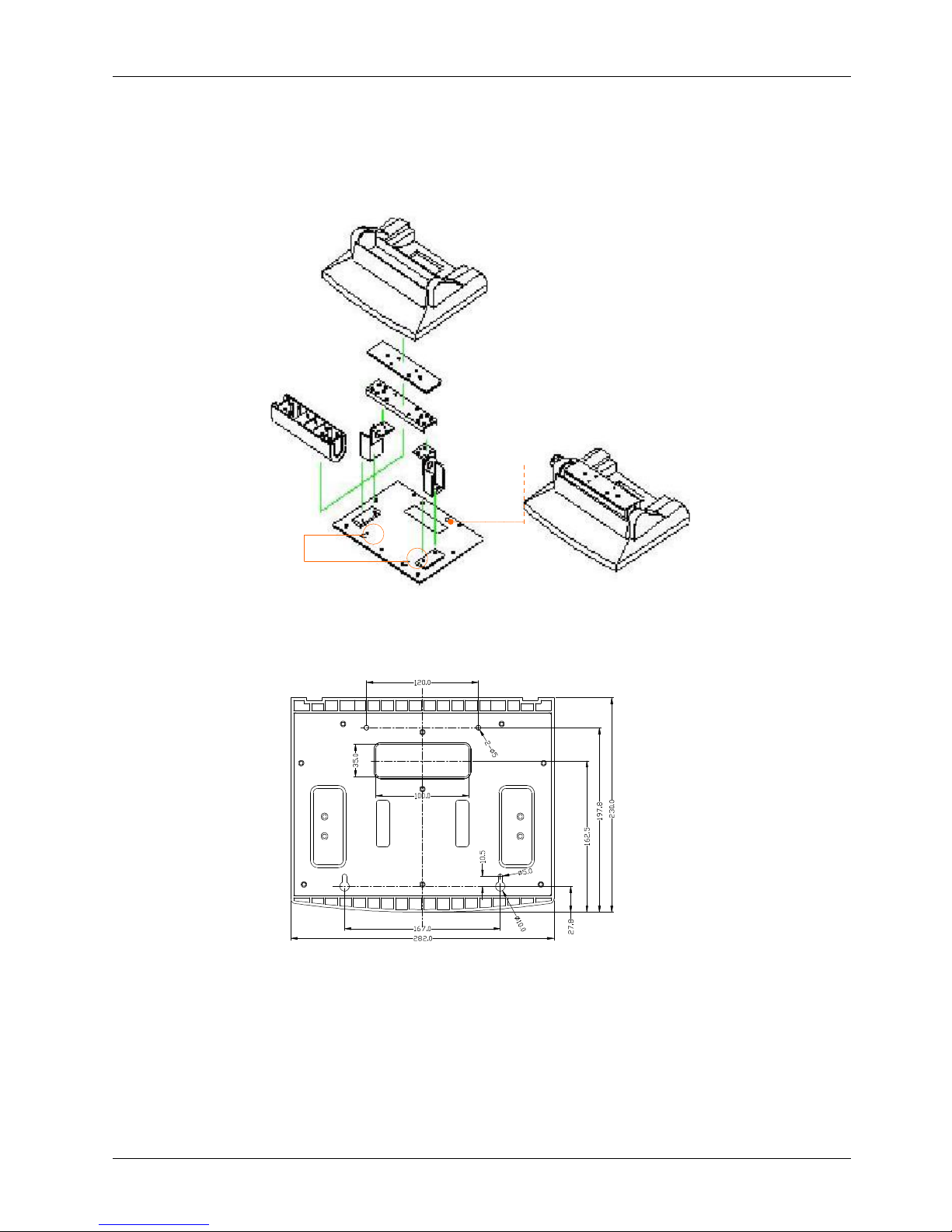
MP1200/MP1500
PEDESTAL
B
ASE AVOCADO HOLES
3.1.3.
Fixed Standing
At the bottom side of the big pedestal, there are two avocado
-shape holes which are used to
retain
the
MP1200/MP1500
to the tab
le with screws. When the unit
is fixed to the table, the
angle from the
main sys
tem to the table can be
tilted
from 45 to 90
0
by swiveling the k
nob on the left side of the
base
cover
and pulling the base up and down.
The following figure illustrates the distance between the avocado holes.
Cable outlet
Avocado
-
shape holes
Page 25

Service
Manual version
1008
MP1200/MP1500
(PC920 Intel 945G)
3-17
3.1.4.
Cable Management
The
MP1200/MP1500
’s pedestal is not only a versatile stand but a functional stand able to manage the
system cabling.
1.
The rectangle
-
shape opening at the bottom side of the
big pedestal can
be used as
a cabl
ing
outlet
.
All the cables
connecting to the I/O ports can come out from this opening, then down to the table.
2.
The two base back covers can
also used
a set of cable management covers. All the cables
connecting to the I/O ports come down in the covers,
and
then out from this opening
at the rear
side of the base.
Page 26
Service
Manual version
1008
MP1200/MP1500
(PC920 Intel 945G)
3-18
3.2.
Wall Mounting and Mobile Applications
The
MP1200/MP1500
system provides 1 set of VESA mounting holes, 75*75mm on the rear side of
the chassis. System integrators can design their special wall mount brackets per the VESA
holes or
obtain market
-
available swing arms for wall mounting, table mounting or mobile applications.
MP1200
VESA
HOLES
OP
1500
VESA
HOLES
Page 27
Service
Manual version
1008
MP1200/MP1500
(PC920 Intel 945G)
3-19
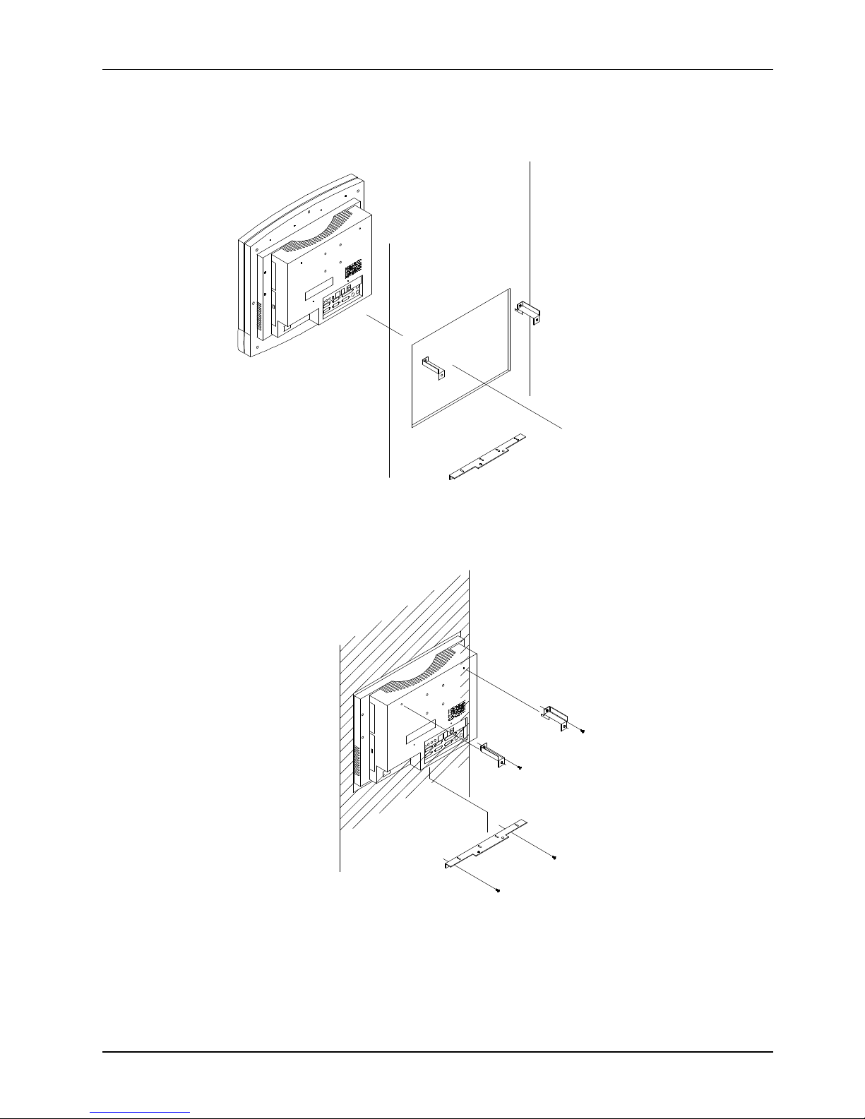
3.3.
Panel Mounting
The
MP1200/MP1500
system provides a set of optional mounting brackets for system panel mounting.
The following figures illustrate the way to use the brackets for panel mounting
.
-
Page 28
Service
Manual version
1008
MP1200/MP1500
(PC920 Intel 945G)
3-20
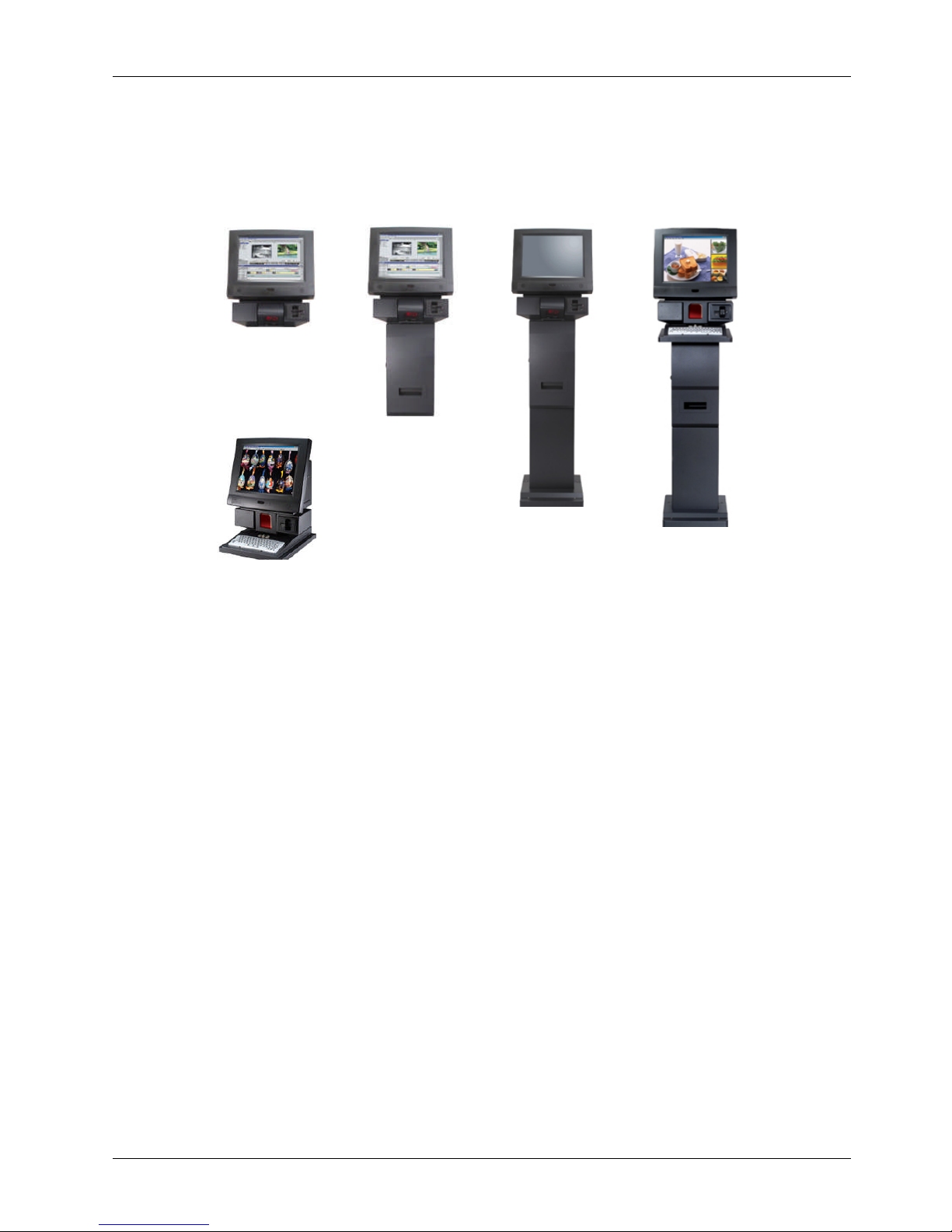
3.4.
Kiosk
Integration
The
MP1200/MP1500
system can also be integrated to a
Kiosk
cabinet to make a ready
-to-
play
Kiosk
terminal. The following is an example of
a
Kiosk
unit integrated with an
MP1200/MP1500
system
. It
is a flexible and robust device that can be mounted virtually anywhere and in any forms including
tabletop, pedestal, pole and wall mounting.
Page 29

Service
Manual version
1008
MP1200/MP1500
(PC920 Intel 945G)
4-21
44..KKnnoocckkiinnggddoowwnntthheePPaanneellPPC
C
This chapter hi
ghlights how to knock down the system
into parts
to access the modules or components inside
the
panel PC
.
Page 30
Service
Manual version
1008
MP1200/MP1500
(PC920 Intel 945G)
4-22
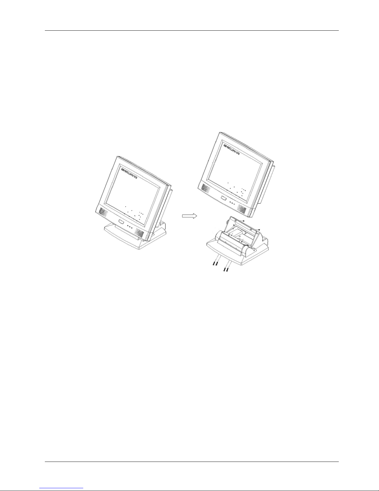
4.1.
Detaching the Pedestal
To access any internal component, the
stand
needs to be removed first.
The following
steps
illustrate
the
way
to disasse
mble the
pedestal from the
panel PC
.1.Detach the
upper
base cover by loosening the two screws used to retain it to panel PC.
2.
There are two
rectangle
opening
s at the bottom side of the pedestal. Insert a long
driver
into
the openings
and remove the four
PMS M4*18 screws
used to retain the base hinges to the
panel PC
.3.Detach the
pedestal from the panel PC.
(1)(2
)
Page 31

Service
Manual version
1008
MP1200/MP1500
(PC920 Intel 945G)
4-23
4.2.
Disassembling the
P
anel PC
The panel PC
itself
is mainly composed of two major parts, one
display
module
and the ot
her PC
module.
Both modules are also made of some sub modules. The following table list
s
the
hierarchy
of
each individual
in the
panel PC.
LEVEL
DECRIPTION
0.1
Panel PC
..2
Display Module
...3
Front Bezel Module
...3
LCD Module
..2
PC Mod
ule
...3
Motherboard
Module
...3
HDD Module
...3
Touchscreen Controller Module
...3
Expansion Door Module
...3
Inverter
Module
...3
Slim CD
-
R/FDD
Module
...3
Power Supply Module
...3
Riser Card Module
...3
PC I/O Cover Module
...3
Rear plastic cover
Module
The following steps highlight the procedure to knock the panel PC into individual
modules
.1.Detach the
rear plastic cover
by loosening
the
seven
s
crews used to retain the
cover to the display
mo
dule.
2.
Detach the stand support bracket by removing the two retaining screws.
3.
Remove the metal PC I/O cover by loosening the
seven retaining screws.
4.
Remove the riser card
module
from the
motherboard
’sESIA slot
.
5.
Disconnect the two power supply
’
s power cabl
es and the power switch cable from the
motherboard
. Disconnect the two 4
-
pole power cables from the HDD and CD
-
ROM.
Remove the
power supply module from the chassis by unscrewing the
four
retaining scre
ws.6.Unplug all the cables on the
motherboard
coming f
rom the CD
-
R/FDD
module. Detach the
CD-R/FDD
module by removing the three retaining screws.
7.
For
MP1500
, d
isconnect the
inverter
cable. Remove the
inverter
cover by loosening the two
retaining screws.
Disconnect the two LCD power wires from the
inverter
.
Remove the
inverter
by
loosening the two retaining bolts.
8.
Disconnect the LVDS cable, IrDA/speaker cable, the two touchscreen cables and power wire from
the
motherboard
.
Detach
the chassis from the display
module
by loosening the six retaining
screws.
9.
Deta
ch the expansion door from the chassis by loosening the three retaining screws.
10.
Detach the touchscreen controller module from the chassis by loosening the two retaining screws.
11.
Detach the IDE cable of the HDD module from the
motherboard
.
Remove the HDD mo
dule from
the chassis by
loosening
the retaining screw.
12.
Remove the
motherboard
from the chassis by unscrewing the
eight
retaining screws.
The panel PC is now knocked down into individual modules.
Page 32
Service
Manual version
1008
MP1200/MP1500
(PC920 Intel 945G)
4-24
(5
)
(5)
(4
)
(1)
(2
)
(A
)
(3)
(3)(B)(A)(6)
(7
)
4.2.1.
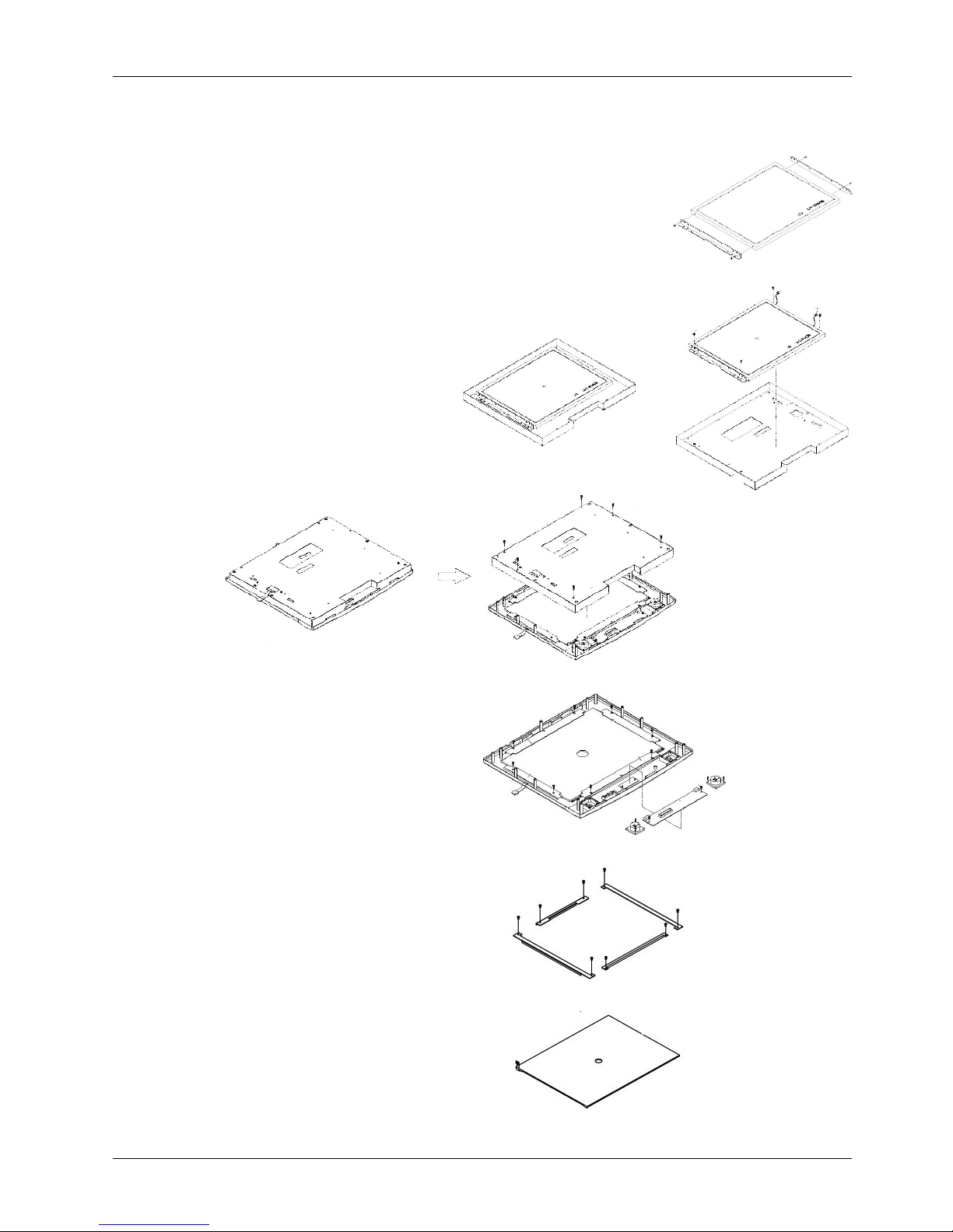
Disassembling the Display Module
The display module (A
) is mainly composed of two modules, one LCD (B) and the other front bezel (C)
modules.
To disassemble the
display module, follow the steps below.
1.
Detach the LCD module (
A
) from the front
the bezel module (
B
) by unscrewing the
six
screws used to fix the t
wo modules
together.
2.
Remove the LCD panel (
1
) from the LCD
holder (2) by unscrewing the
four
screws
used to retain t
hem together.
3.
For
MP1200
, detach the LCD
power wires from the
inverter
and remove the
inverter
from the
LCD holder by loosening the two
reta
ining screws.
For
MP1500
,detach the two LCD brackets (
3)from the LCD panel by
unscrewing the two screws at
each side.
4.
Disconnect the two speaker
wires and the IrDA/speaker
cable from the speaker
board (4).
5.
Remove the IrDA/speaker
board (4) by
unscrewing the
two screws used to fix it to
the front bezel.
6.
Remove the two speakers (
5)from the front bezel by
unscrewing the
two
retaining screws at each
side.
7.
Remove the touchscreen (7)
from the front bezel by
unscrewing the
ten
screws
used to retain t
he four touch
brackets (6) to the front
bezel.
Page 33
Service
Manual version
1008
MP1200/MP1500
(PC920 Intel 945G)
4-25
4.2.2.
K
nocking down
the
panel PC
’
s Individual Modules
The
panel PC
is now separated into
several
individual modules. You
may
need to
further
knock some
modules down into parts
for repair purpose
. Refer to t
he following sections to detach the components
from these modules.
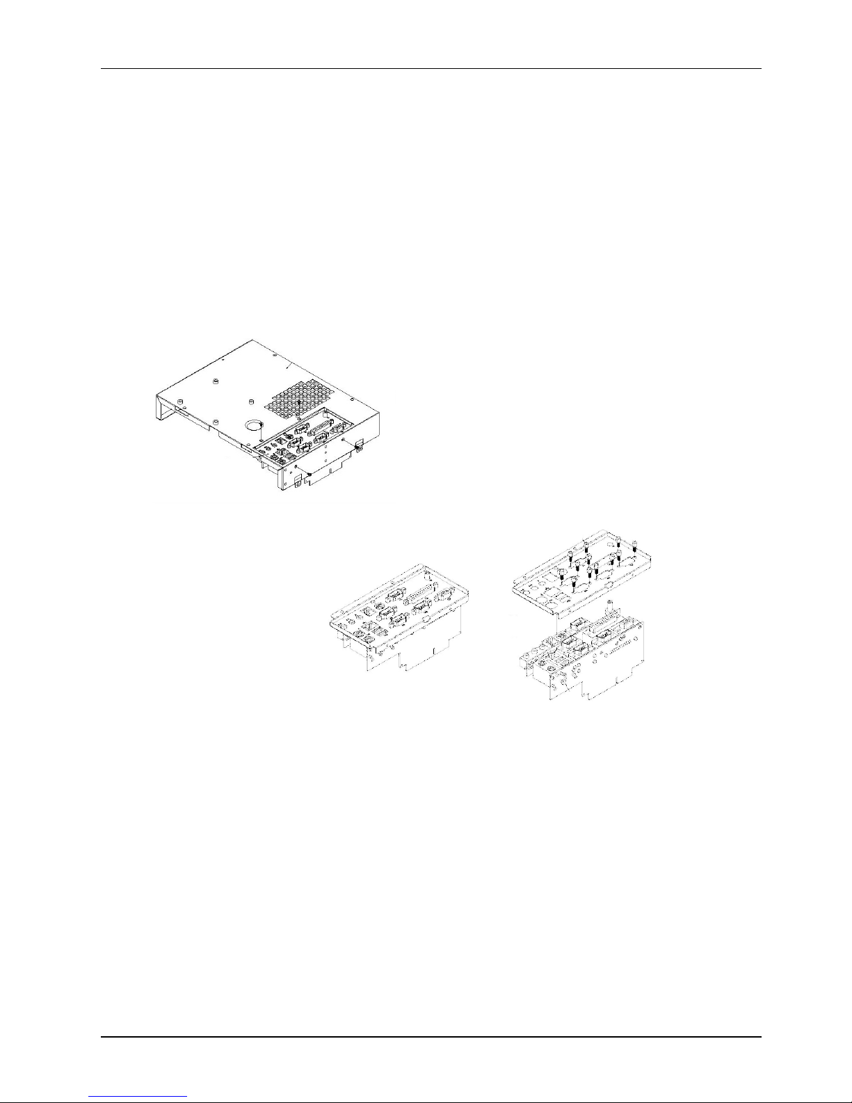
4.2.2.1.
Disassembling the
PC
I/O M
odule
The I/O module is mainly composed of
two I/O boards
.
All the onboard I/O signal of the
MP1200/MP1500
’smotherboard
is connected to
these
boards for external
device connection.
1.
Detach the I/O board module (
1
) from the
PC
I/O
cover
(2)
by unscrewing the
four
retaining
screws.
2.
Detach the
22P*2
flat cable used to link the IO
-
005 (
3
) and IO
-
006 (
4
) boards.
3.
Detach the two IO boards from the I/O bracket
(5) by loose
ning the securing bolts and retaining
screw
.
(2)(1)(3)(4)(5)(1
)
Page 34
Service
Manual version
1008
MP1200/MP1500
(PC920 Intel 945G)
4-26
4.2.2.2.
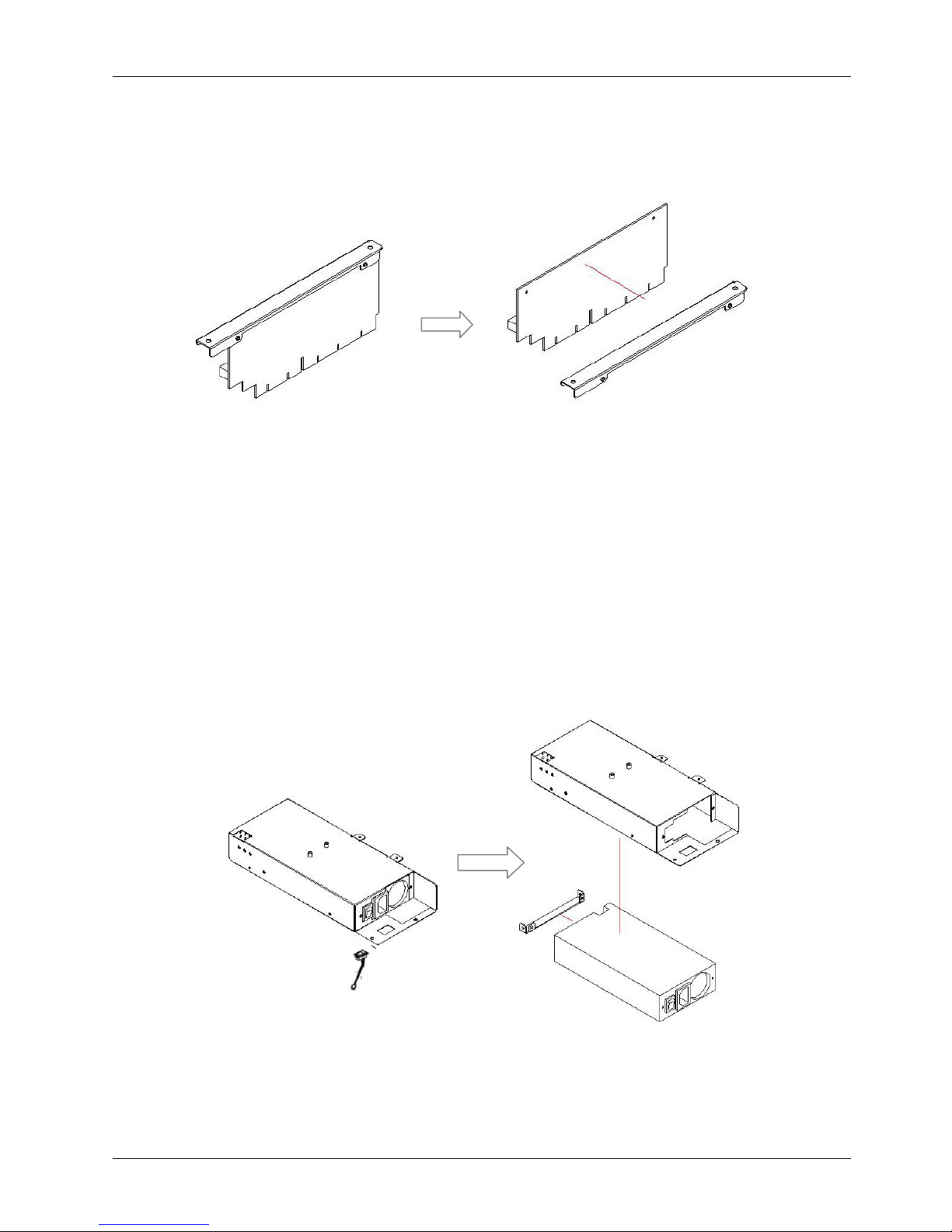
Disassembling the Riser Card Module
The riser card
module
is used for plugging add
-on-
cards. To detach the riser card (1) from its bracket
(2), simply remove the two retaining s
crews.
4.2.2.3.
Disassembling the Power Supply Module
1.
Loosen all the cable ties used to tie the power cables on the power module (2)
.2.Remove the power switch extension cable (1) from the power module (2)
.3.Remove the power supply (3) from the power
bay (4) by unscrewing the four retaining screws
.4.Detach the small power bracket (5) from the power supply by removing the two retaining screws
.
(1)(2)(3)(4)(1)(2)(5)
Page 35
Service
Manual version
1008
MP1200/MP1500
(PC920 Intel 945G)
4-27
(2)(1)(5)(3)(6)(4)(2)(1)(3)(7)
4.2.2.4.
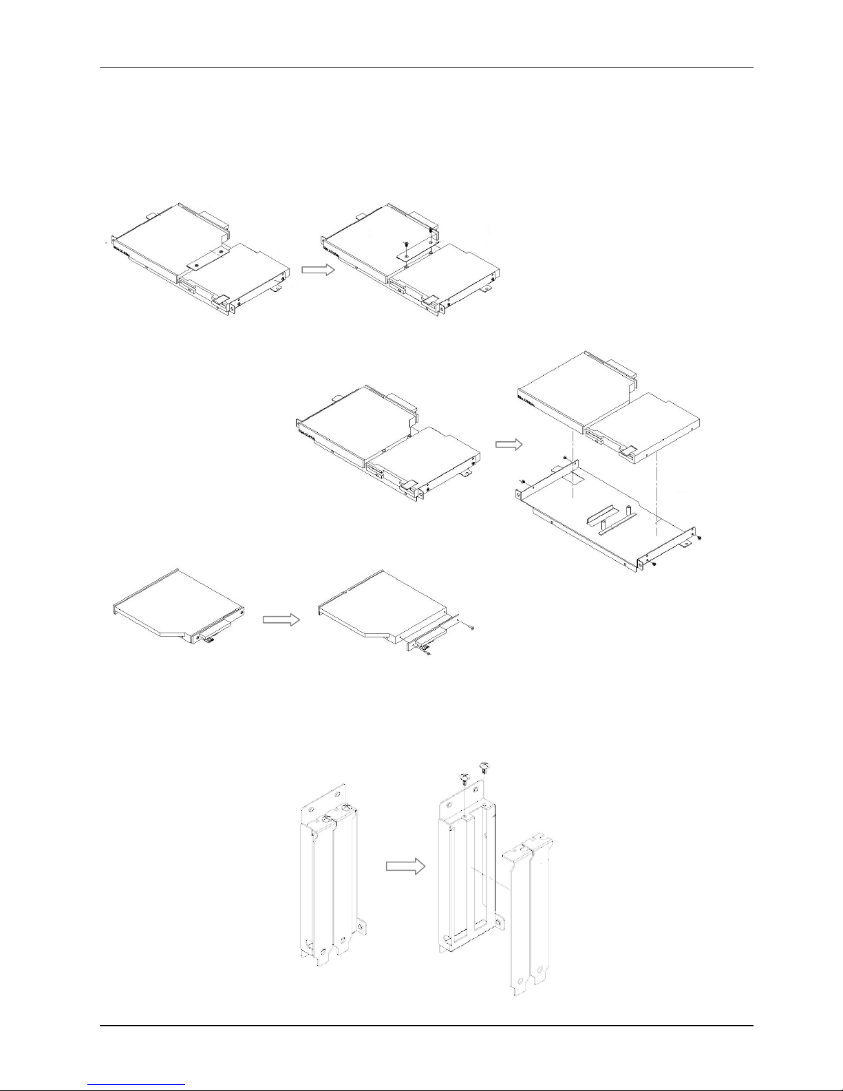
Detaching the slim CD
-
R/FDD
1.
Detach the retaining bracket (2) from the CD
-
R/FDD
modul
e (2)
2.
Remove the
CD-ROM
module
(3) and
FDD
(4) from the device bracket (5) by
loosening
the four
retaining screws.
3.
Detach
theCD-
ROM board (6) from the CD
-
ROM (7) by
loosening
the two retaining screws.
4.2.2.5.
Disassembling the Expansio
n Door
Detach the two metal brackets (1) from the expansion door (2) by removing the two retaining screws.
Page 36
Service
Manual version
1008
MP1200/MP1500
(PC920 Intel 945G)
4-28
(2)(1)(2)(1)
4.2.2.6.
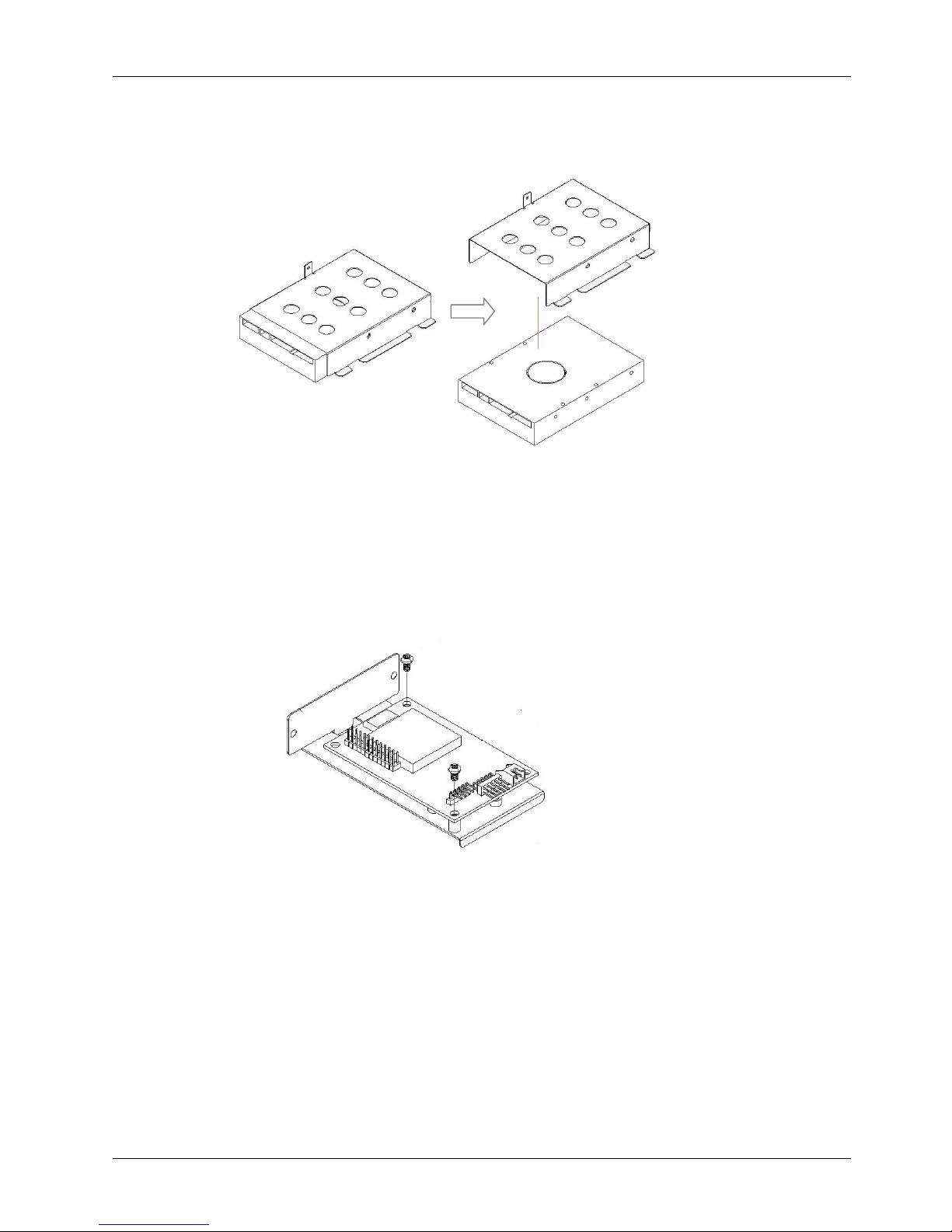
Detaching the HDD
1.
Detach the HDD ribbon cable from the HDD (1).
2.
Remove the HDD from the HDD bay by
loosening
the
four
retaining screws.
4.2.2.7.
Detaching the Touchscreen Controller
1.
Detach the tocuhscreen controller (1) from the device bracket by removing the four retaining
screws.
2.
Disconnect the two cables from the controller.
Page 37
Service
Manual version
1008
MP1200/MP1500
(PC920 Intel 945G)
4-29
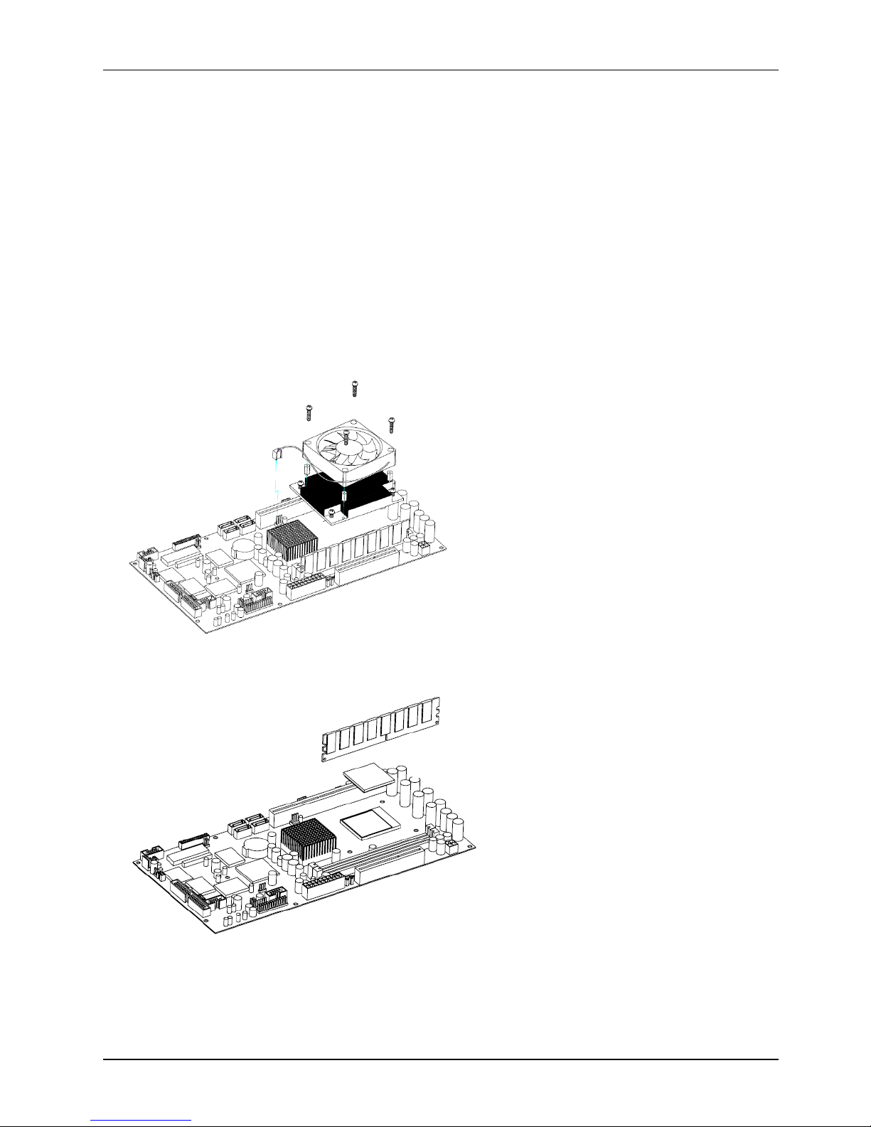
4.2.2.8.
Removing CPU & DDR
The two components you
might need to remove from the motherboard are the CPU and DDR memory
module. Please note that the Celeron M CPU in
MP1200/MP1500
system is an onboard BGA type and
irremovable
, therefore, the CPU in
MP1200/MP1500
is not upgradeable unless the motherboard
is
replaced.
T
he following steps illustrate the way to remove the
Pentium M CPU (2) from the
motherboard and DDR from both motherboards.
1.
Unplug the CPU fan cable from
FAN1
on the motherboard.
2.
Remove the fan by loosening the four retaining screws.
3.
Release
the four screws to remove the heatsink.
4.
Remove the heatsink on the CPU.
Then remove the CPU
by pulling the lever out a little and
raising it, then lifting out the existing CPU from the socket.
5.
Cut the cable ties on the DDR sockets.
There are two white
eject levers at each end of the DDR
socket. Push them outward
s
until they separate from the two vertical posts.
6.
Holding the
DDR
with the notch on the upper right corner, then
remove
the
DDR fr
omthe DDR
socket at 90
angle.
(1)
(2)(3)(4)(5
)
Page 38

Service
Manual version
1008
MP1200/MP1500
(PC920 Intel 945G)
5-30
55..BBuuiillddiinngguupptthheePPaanneellPPC
C
This chapter overviews the installation of the
MP1200/MP1500
’s internal components and devices.
Sections include:
Display Module Assembly
PCModule Assembly
Pedestal
Assembly
Panel PC Integrating
Page 39
Service
Manual version
1008
MP1200/MP1500
(PC920 Intel 945G)
5-31Af
ter knocking down the
system
into parts
or rep
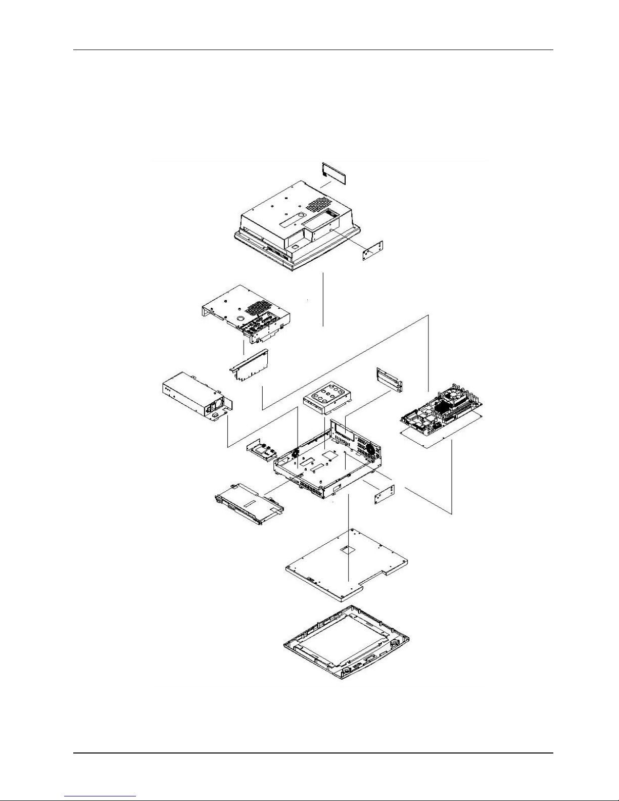
lacing new components, you need to build up the
system again.
The
MP1200/MP1500
is composed of
2
major parts, the
panel PC
and
the
stand
.
The
panel PC
without stand
is made of two individual modules, one
display
module
and the other
PC
module
.
In terms
of LCD size, the
MP1200/MP1500
has two models, one 12.1”
and the other 15
”. The
assembly of the two models is basically the same except the LCD assembly. The followin
g diagram
highlights the
majo
r parts that make up the
MP1200
main system
.
(
1)
(A)
(5)
FMS M3*5 (3)
(6)
PMS 3*6 (6)
(11)
FMS M3*5 (9)
(12)
(2)
PMS 3*5 (8)
(3)
FMS M3*5 (1)
(4)
FMS M3*5 (2)
FMS M3*5 (3)
(9)
(10)
FMS M3*5 (4)
(15)
FMS M3*8 (7)
(14)(13)
MP1200
ASSEMBL
Y
Page 40
Service
Manual version
1008
MP1200/MP1500
(PC920 Intel 945G)
5-32
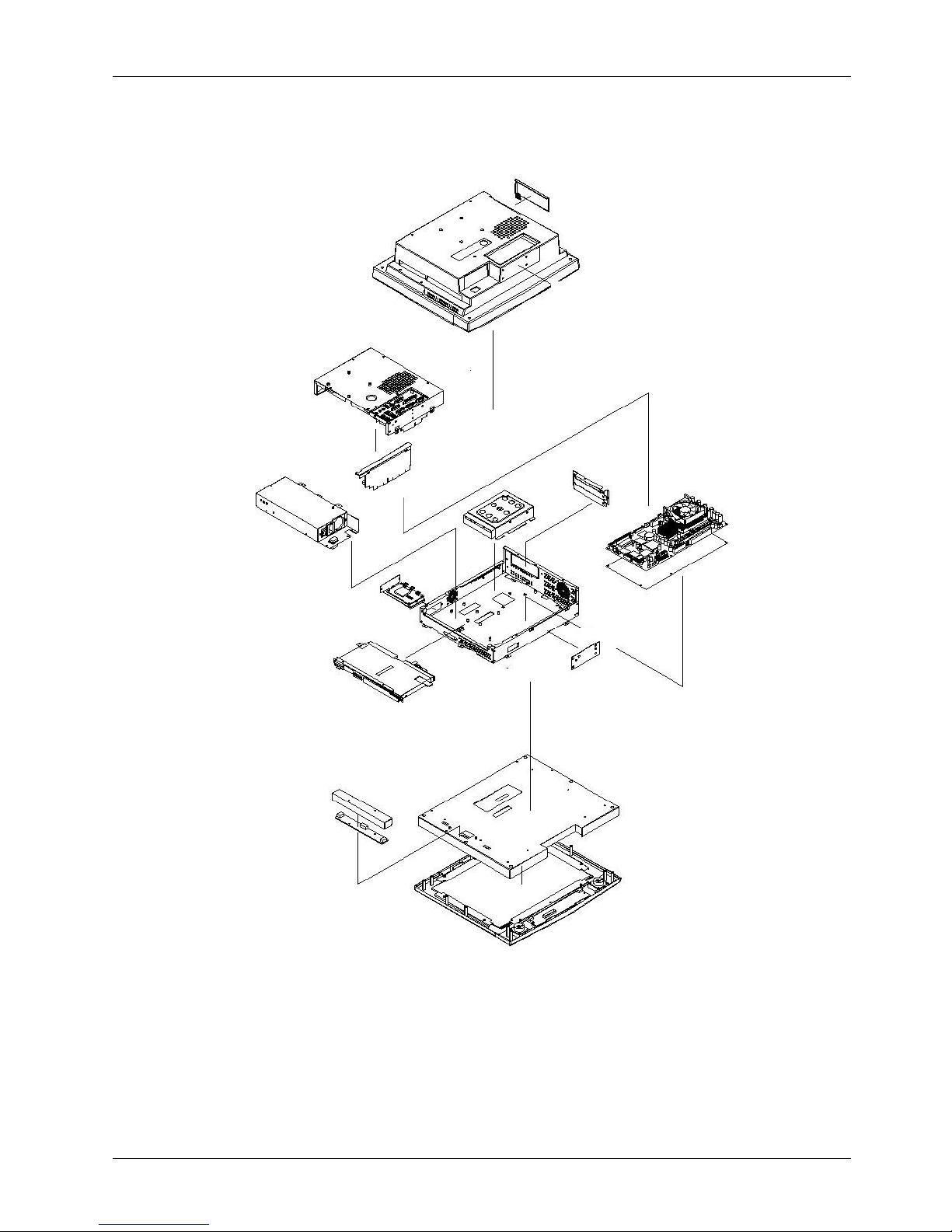
The fol
lowi
ng diagram shows the
majo
r parts that make up the
MP1500
main system.
(
1)
(A)
(5)
FMS M3*5 (3)
(6)
PMS 3*6 (6)
(7)
(11)
FMS M3*5 (9)
(12)
M
3*15 bolt (2)
(2)
PMS 3*5 (8)
(3)
FMS M3*5 (1)
(4)
FMS M3*5 (2)
FMS M3*5 (3)
(9)(8)PMS 3*6 (2)
(10)
FMS M3*5 (4)
(15)
FMS M3*8 (7)
(14)(13)
OP150
0
ASSEMBLY
Page 41
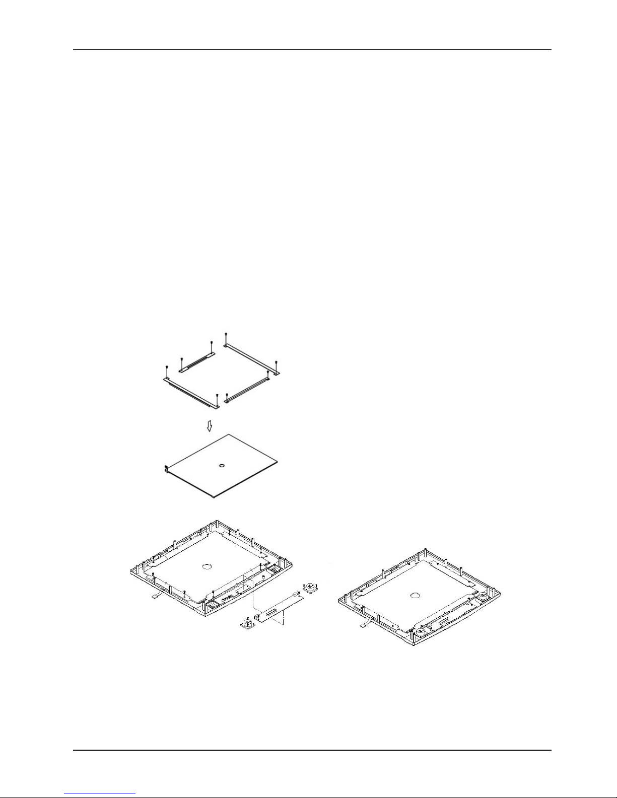
Service
Manual version
1008
MP1200/MP1500
(PC920 Intel 945G)
5-33
(5)
PMS 2*8 (2)
(4)
PMS 3*5 (2)
(5)
PMS 2*8 (2)
(1)(2)PMS 3*6 (3)
(3)
PMS 3*6 (2)
(3)
PMS 3*6 (3)
(3)
PMS 3*6 (2)
(3)
5.1.
Display
Module
Assembly
The
display
module
consists of two modules, one
front bezel
module
and the other LCD module.
5.1.1.
Front Bezel
Assembly
The following steps illustrate th
e ways to assemble
touchcreen
and
some accessories
to the front
bezel.
1.
Refer to the figure below.
There are
four
one-side adhesive foam sponges
.
Attach the four 1mm
sponge tapes to
the
front bezel
(1)
. The sponge tapes act as
bumpers
to absorb the press
ure when
the touchscreen is fixed to the front bezel
.2.There are 4 metal brackets
(3)
used to fix the touchscreen
(2)
to the front bezel. The metal
brackets have to be taped with
foam sponges.
3.
Put the touchscreen to the bezel with its active side facing d
ownwards and its white flat cable at the
left side. Make sure the touch panel
’
s active area is aligned in the opening of the front bezel.
4.Ma
ke sure the white flat cable comes out from the underneath of the left bracket.
Then, fix the
touch
screen
to the fr
ont bezel with the four metal brackets
and retain them together
with
three
PMS M3*6
screws
for
the up and down sides and two PMS M3*6
screws
for the right and left sides
.
The foam sponges
are used
bumpers to absorb the pressure caused by the four metal bra
ckets
when driven tightly to the touchscreen.
5.
Fix the
IrDA/
SPK
board
(4)
to the
front bezel
with two
PMS M
3*5screws.
6.
The two speakers
(5)
are to be fixed to the right and left sides of the
SPK
board
with
two PMS
2*8
screws for each
. The speaker wires are
to be connected to the 2
-
pin
CN1
and
CN2
on the
IrDA/
SPK
board.
Page 42
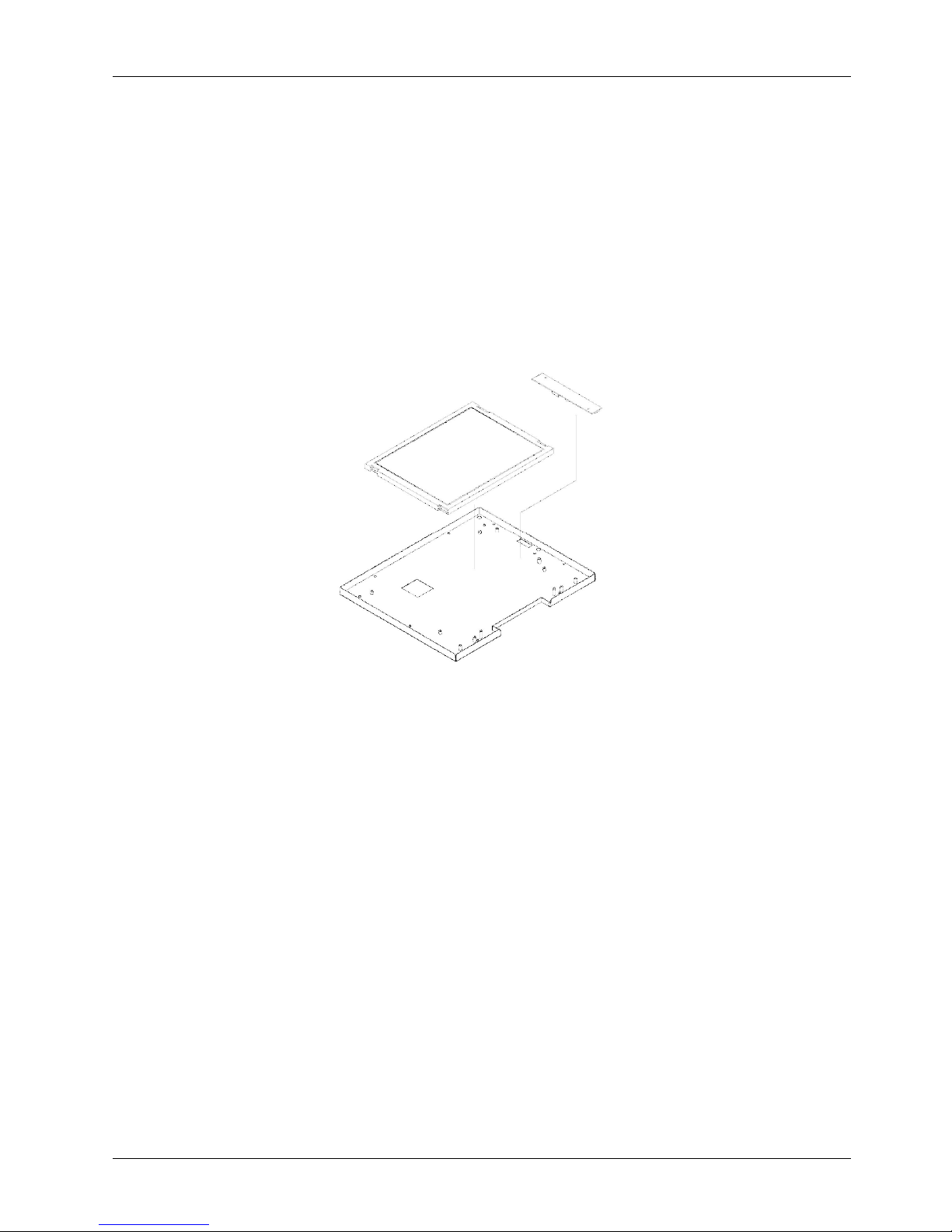
Service
Manual version
1008
MP1200/MP1500
(PC920 Intel 945G)
5-34
5.1.2.
LCD Module
Assembly
The assembly of
MP1200
LCD module sligh
tly differs from that of
MP1500
.
5.1.2.1.
MP1200
LCD Assembly
The standard LCD used in
MP1200
is 12
.1”
LVDS
LG.Phi
lip LB121S03 or its
equivalent.
The following
figure illustrate
s the steps to integrate
MP1200
LCD module.
1.Attach the insulator to the inverter.
2.
The inverter cable is a 4
-
pin to 4
-
pin
wire
with wafer connectors at both sides. Connect one end to
inverter
first.
3.
The inverter module
is
to be fixed at the right middle side of the LCD holder with the up side down.
4.
Plug one end of the LVDS cable
to
the LCD connector at
rear side of the LCD
.5.Connect the
LCD’s pink
-
white
power
wires from the LCD to the
inverte
r.6.
Retain
the LCD panel to the LCD holder
(3)
with
two
PMS M
3*6screws
at each side
.
(1)
PMS 3*6 (4)
(2)(3
)
MP1200
LCD
MODULE ASSEMBLY
Page 43
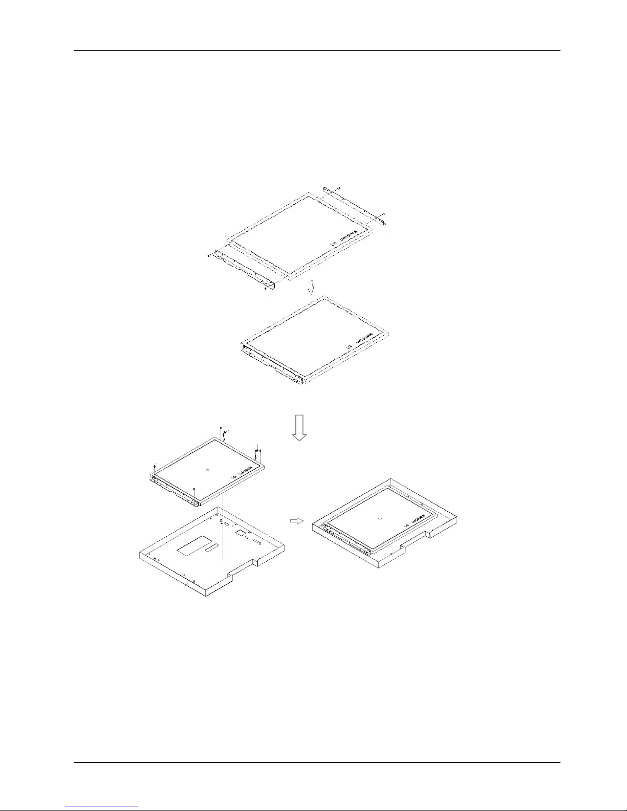
Service
Manual version
1008
MP1200/MP1500
(PC920 Intel 945G)
5-35
5.1.2.2.
MP1500
LCD assembly
The standard LCD used in
MP1500
is 15
”
LVDS
LG.Philip LM151X08 or its
equivalent.
The following
figure
illustra
tes the ste
ps to integrate
MP1500
LCD module.
1.There are two LCD brackets
(1)
used to fix to the LCD panel to the LCD holder from the
left&right
sides.
Fix the LCD brackets (1) to the LCD panel (2) with
two PMS M3*5 screws
at each side.
2.Ma
ke sure the LCD
’
s pink
-
white power wires come
out from two openings at the
right
side of the
LCD holder.
Fix the LCD panel to the LCD holder
(3)
with
two
PMS M
3*6screws
at each side
.OP1500
LCD
MODULE ASSEMBLY
PMS 3*6 (2x2)
(3)
(1)
PMS 3*5 (2)
(1)
PMS 3*5 (2)
(2)
Page 44
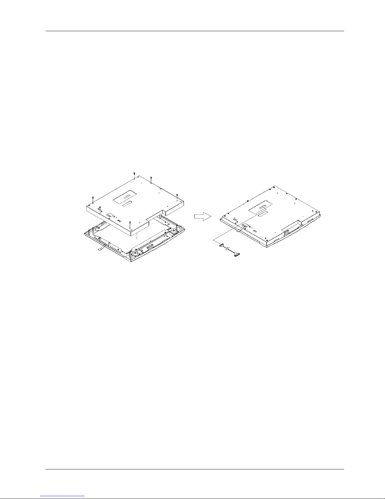
Service
Manual version
1008
MP1200/MP1500
(PC920 Intel 945G)
5-36
D
ISPLAY
MODULE ASSEMBLY
(2)(1
)
PMS 3*8 (6)
(3)
5.1.3.
Display
Module
Integration
After finishing the
LCD
module installation, the module is to be assembled to the
fro
nt bezel
module
to make a complete display module.
1.
Use
dust
air blower to blow any dust between the LCD and touchscreen before
they
are integrated
together. Retain the LCD module
(2)
and the
front bezel
module
(1)
together with
six
PMS M
3*8screws.
2.
Make su
re the LCD
’spink
-
white power wires com
e
out from two
rectangle
openings at the left
upper and lower
sidesof the LCD holder.
A
nd make sure the
touchscreen flat cable
comes out
from the
rectangle
opening at the left
middle
side of the LCD holder
.3.There is
anIrDA/
speaker cable with
one 9P*2 box header at one end and the
other
13P*2 box
header
at
the other
end.Plug
the 9P*2
endtoCN3on the
IrDA/
speaker board.
.4.The
LVDS cable
(3)
is to be
firmly
plugged to the LCD connector located at the rear side of t
he LCD
panel first.
Insert the other end underneath the LCD holder and have it come out from the
small
opening
at the middle side of the LCD holder.
The
display module installation is now completed.
Page 45

Service
Manual version
1008
MP1200/MP1500
(PC920 Intel 945G)
5-37
5.2.
PC Module
Assembly
The
MP1200/MP1500
panel
PC’s core engine is
a Celeron
M
/Pentium
®
M
multimedia
panel PC
.
The
system control board
(2)
and other internal devices such as HDD
(3)
and power supply
(5) are to be
housed in a
chassis (A)
. The system’s performance depends on the installed CPU and the
capacity of
the system memory and hard disk drive. In some circumstances, you might intend to upgrade or
maintain the system.
The hard disk drive can be removed by releasing the thumbscrew at the upper
side of the chassis.
By removing the
PC I/O
cover
(7)
, the internal components such as CPU, DDR,
and power supply can be easily accessed for maintenance and upgrade.
The PC module is composed of eight individual
modules
,
motherboard
module
,
HDD module
,touchscreen controller module
, e
xpansion door module
, s
lim CD
-
R/FDD
module
,
inverter
module
,power supply module
, r
iser card module
and P
C cover module
Thesemodules
are to be integrated to individual modules first, then
,
installed together
with
the
display
module
and
rear plastic cover to make
a
complete P
C module
.
Page 46
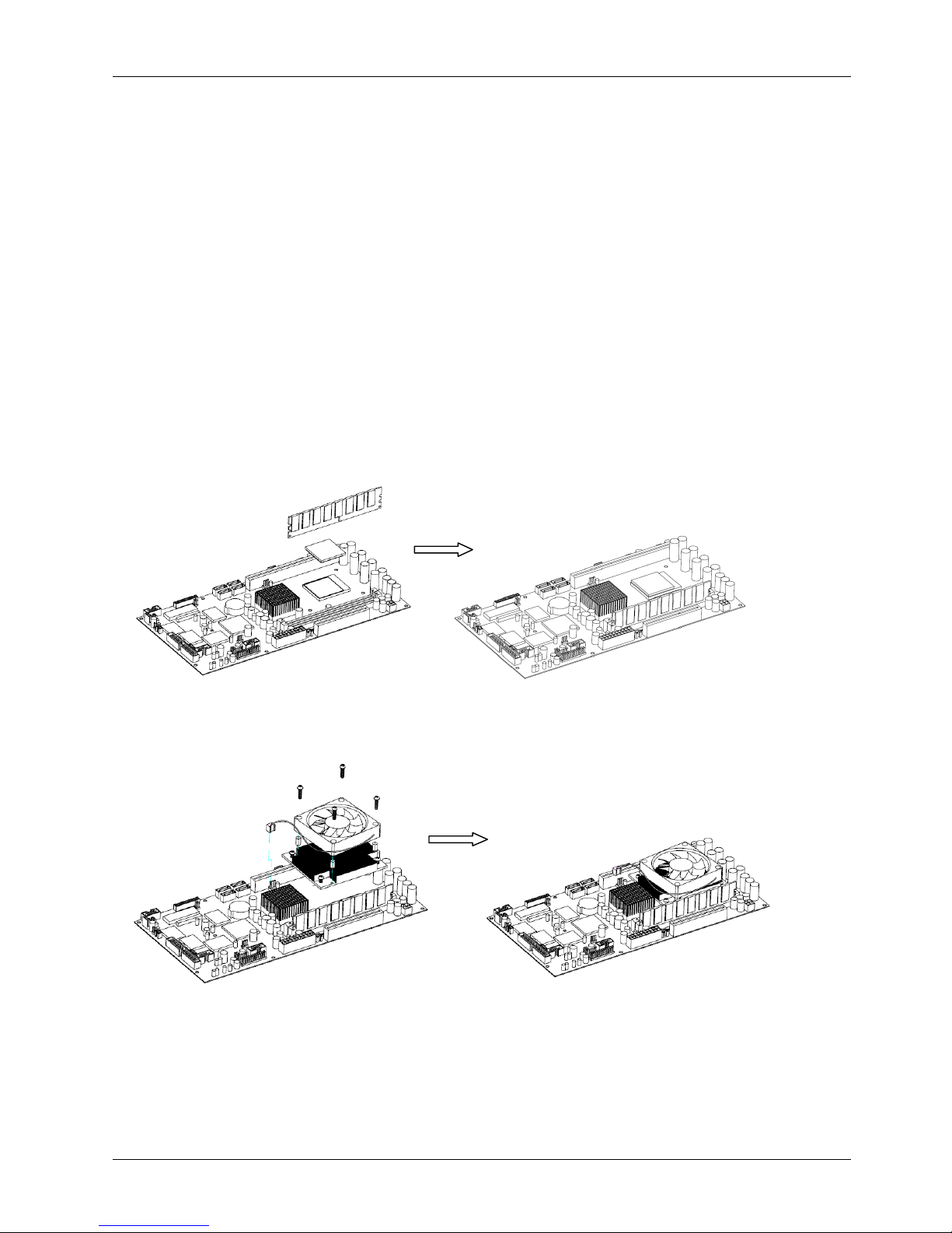
Service
Manual version
1008
MP1200/MP1500
(PC920 Intel 945G)
5-38
5.2.1.
Motherboard
Assembly
5.2.1.1.
I
nstalling the CPU
The motherboard provides one
LGA775 Socket, able to adapt a
LGA775 Socket
Intel
C
ore 2 Duo
CPU.
Please note that the Core 2 Duo CPU in
MP1200/MP1500
system is an onboard BGA type and
irremovable
, theref
ore, the CPU
is not upgradeable unless the motherboard is replaced.
T
he following
steps illustrate the way to remove the CPU (2) from the PC
920
motherboard and DDR from both
motherboards.
The CPU
in the
MP1200/MP1500
system
must come with a heat sink
and
cooling fan
on to avoid overheating. To install or upgrade a new CPU
for
MP1200/MP1500
system
, follow the
instructions below.
1.
Pull the CPU lever up by pulling it outwards a little bit, then upwards.
To insert the CPU
(1)
into the
socket
(2)
, the notc
h on the corner of the CPU (the corner with golden
or white
dot) should point
toward the end of the socket lever. If the insertion of the CPU to the socket is not easy, check
whether the CPU pins correspond with the holes on the socket.
2.
After insert
ingthe CPU into the socket, pull the lever down to make sure the CPU is in place.
3.
Put the heat sink set (3) on the CPU and lock four screws at each side.
4.
Put the fan (4) on the heat sink and lock four screws at each side..
5.
The CPU cooling fan comes with a p
ower
wire (5)
. Connect the power
wire
to the 3
-
pin power
connector
FAN1at
the
left side of the CPU retention
on the motherboard.
Tie the power wires
together with a nylon cable tie.
(1)(2)(3)(4)(5)(7)
Page 47

Service
Manual version
1008
MP1200/MP1500
(PC920 Intel 945G)
5-39
5.2.1.2.
Installing the DDR Memory Module
The
panel PC
’scontrol board provides
2x240-pin DDR socket
s
, able to support DDR memory up to
2
GB. To install the memory module, follow the instructions below.
1.
Find the
240 pin DD
R2socket
s
on the
motherboard
.2.There are two white eject levers at each end of the DDR s
ocket. Push them outward until they
separate from the two vertical posts.
3.
Holding the memory module with the notch on the upper right corner, then insert the memory
module into the DDR
2
socket at 90
angle.
4.
Push the two eject levers toward the vertical po
sts until they click into place. The memory
module is now upright.
5.
Retain the memory module
(7)
to the DDR
2
socket by firmly fastening the DDR and the eject
levers together with nylon cable ties.
The system is able to auto detect the new memory size and t
here is no need to change the system
configuration after installation.
Make sure that the memory module you are using can handle the specified DDR MHz. Inadequate
memory module
might low down the system performance or
make the computer unable to boot up.
Page 48
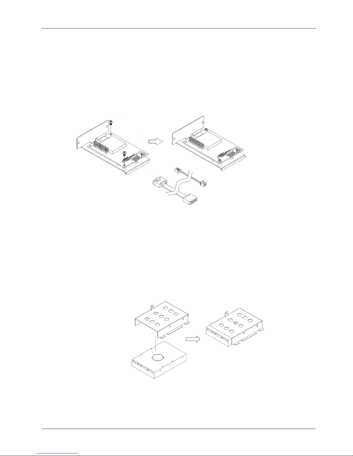
Service
Manual version
1008
MP1200/MP1500
(PC920 Intel 945G)
5-40
5.2.2.
Touchscreen Controller
Assembly
For easy maintenance in the future, the
touchscreen
controller is to
be
installed to a bracket rather
than to the system compartment directly.
1.
For Elo touch, the touchscreen cable
(3)
is a flat cable
with 5P*2
box headers
at both sides
. One
end is connected to
P3on
the touchscreen controller
(1)
first.
2.
There is a
2P
(black & red)
power wire
(4)
to provide the power source for the touchscreen.
Connect one end to
P2
on the
controller.
3.
Make the controller
’
s coach chip
(5) at the upper side.
Retain
the touchscreen controller to the
bracket
(2)
with
two
PMS M
3*5screws.
`
5.2.3.
HDD Module Assembly
The panel PC is able to accommodate a 3.5
”
HDD. It is to be integrated to the drive bay first, then to
the chas
sis.1.Retain
the hard disk drive (1) to the HDD
bay(2)
with
four
FMS
6#32 5L
screw
at each side
.2.Connect one end of a 20P*2
HDD
ribbon
cable
to the hard disk.
HDD
INSTALLATION
(2)
(1)
FMS 6#32 5L (4)
(2)
(1)
PMS M3*5 (2)
(3)(4)(5)
Page 49
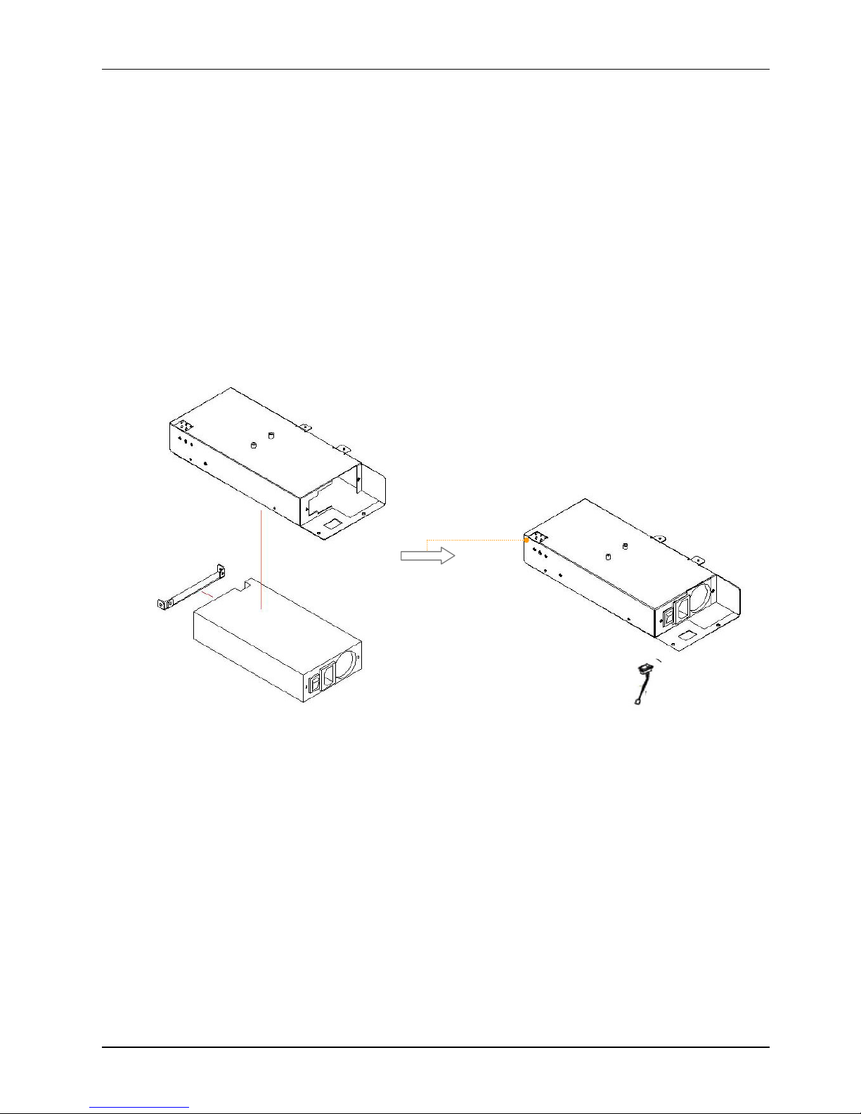
Service
Manual version
1008
MP1200/MP1500
(PC920 Intel 945G)
5-41
FMS 6#32 5L (2)
5.2.4.
Power Module Assembly
The power supply is to be integrated
to a
power
bay
befo
re it is installed to the panel PC. The following
figure
illustrates
the steps to assemble the ATX power module. For the specification of the power
supply, please refer to APPENDIX.
1.
Attach the power bracket (2) to the power supply (3) and fix them togethe
r with
two
FMS
6#32 5L
screws. This small bracket is used to prevent the power supply from moving around in the power
bay.2.
Insert the power supply to
the
power bay (1) and fix them together with
two
FMS M
3*5
and two
FMS
6#32 5L
screws.
3.
Protect the front
section
power cables with a nylon protector. The nylon protector is to prevent
the power wires from being cut by the metal brackets.
4.
Attach two nylon adhesive cable tie bases to the side of the power bracket.
5.
Retain the power cable bundle to the mounti
ng base with a cable tie.
6.
Insert
a
power switch
(4) extension cable
to
the
power bracket (
1
).
(1)
(2)
(3)
The power cable
coming out from
the
opening
and
connected to the
MB’s ATX power
connector.
FMS 3*5 (2)
FMS 6#32 5L (2)
P
OWER MODULE ASSEMBLY
(4)
Page 50
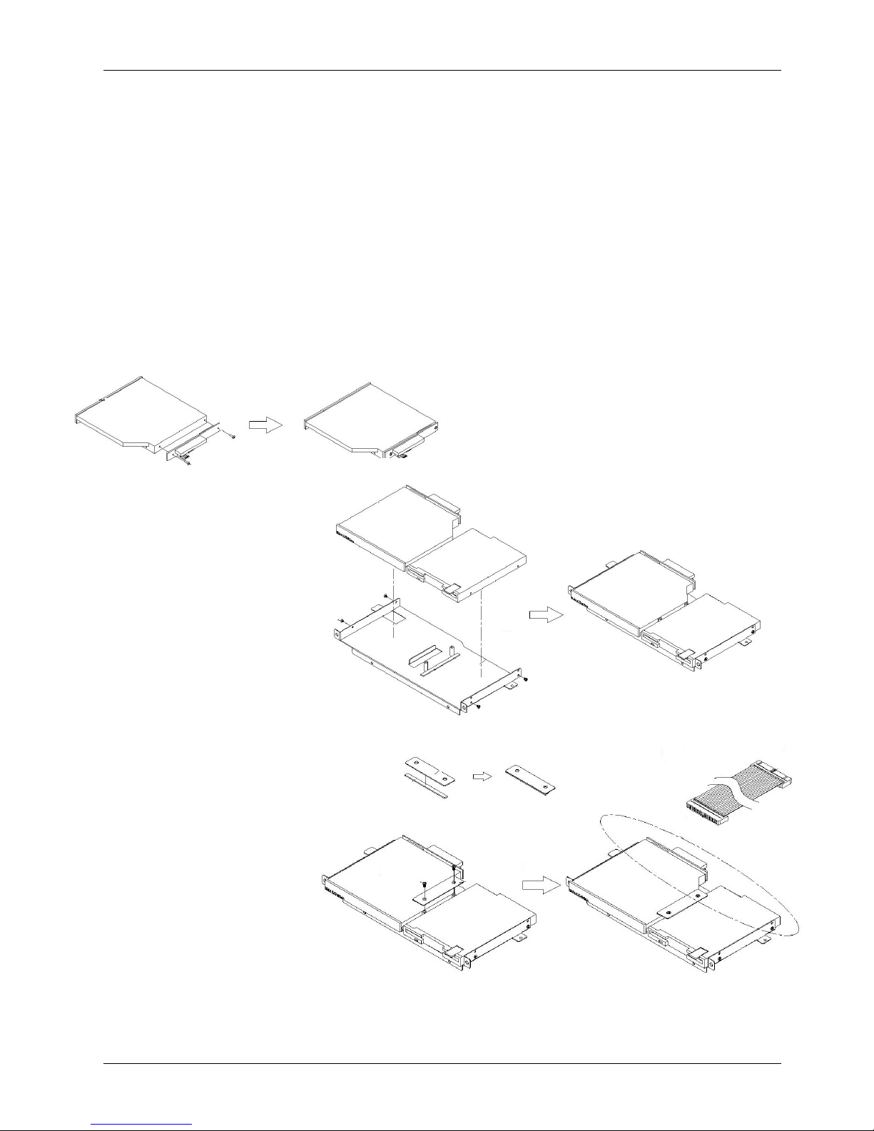
Service
Manual version
1008
MP1200/MP1500
(PC920 Intel 945G)
5-42
(1)(2)IMS 2*2.5
(2)
(3)
(3)(4
)
IMS 2*2.5
(2)
(5)
IMS 2*6 (2)
(6)
FMS M3*5 (2)
(7)
5.2.5.
FDD/CD
-
ROM Assembly
The following steps show the ways to install an internal CD
-
ROM or DVD
-
ROM and floppy disk drive.
1.
Att
ach the CD
-
ROM board (
1
) to the slim CD
-
ROM (
2
) and fix them together with
two TMS 2*8
screws to make a CD
-
ROM module (3).
2.
Insert the CD
-
ROM module
(3)
to the CD
-
R/FDD
bracket (
4
) and fix them together with
two
IMS
M2*2.25
screws.
3.
There is a 40
-
pin CD
-
ROM
ribbon
cable
(7)
. Connect one end to the CD
-
ROM board.
4.
Attach one end of the 26
-
pin FDD flat cable
to the slim floppy disk drive (
5
) first.
5.
Insert the FDD module to the
right side of the
CD-R/FDD
bracket and fix them together with
two
IMS 2*6
screws.
6.
There is a small metal bracket (
6)taped with foam
sponge
used to firmly fix the CD
-
ROM and FDD
modules to the CD
-
R/FDD
bracket.
Retain this bracket to the device bracket with two FMS M3*5
screws.
This small bracket is to prevent the CD
-
R/FDD
from moving
when installed to the
FDD/CD
-
ROM bracket.
Page 51
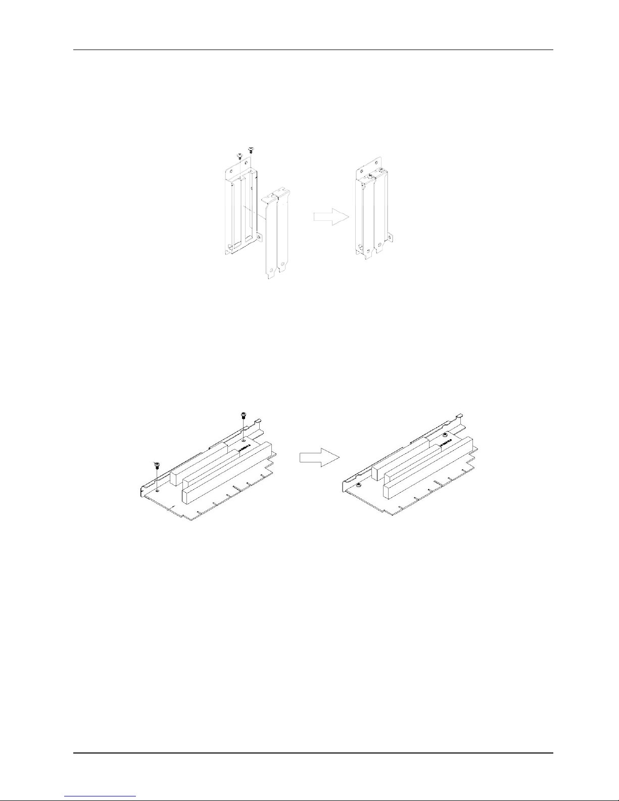
Service
Manual version
1008
MP1200/MP1500
(PC920 Intel 945G)
5-43
5.2.6.
Expansion Door
Assembly
If no add
-on-
card is to be used with the system, fix the two metal brackets
(1)
to the expansion door
(2)
with two TMS 3*6 screws. If an add
-on-
card is
to be used with the system, then only fix one metal
cover to the expansion door.
5.2.7.
Riser Card
Assembly
Retain the riser card
(1)
to the riser card bracket
(2)
with two PMS
M
3*5 screws.
(1)(2
)
TMS 3*6 (2)
(2)
(1)
PMS 3*5 (2)
Page 52
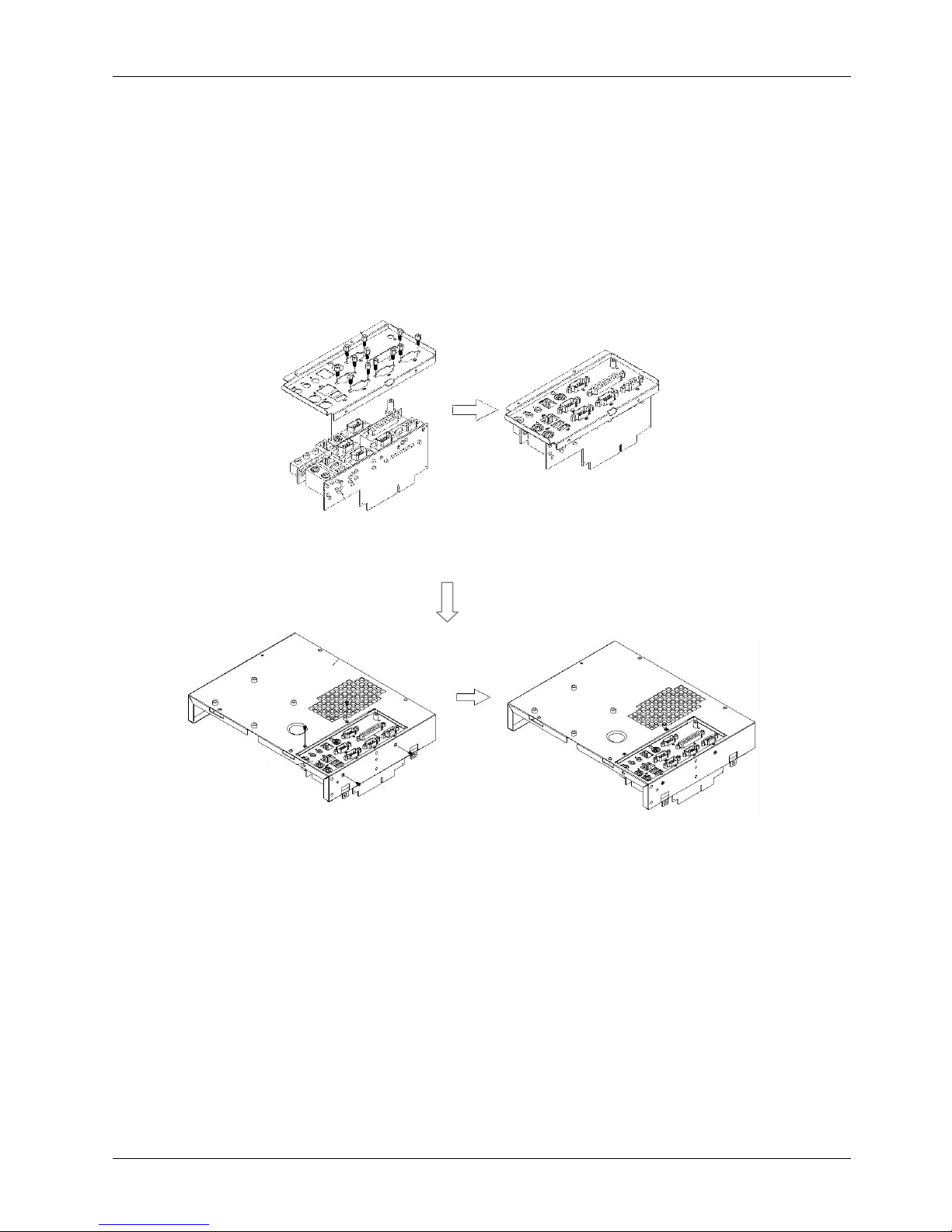
Service
Manual version
1008
MP1200/MP1500
(PC920 Intel 945G)
5-44
(3)
(1)
Bolts 4*1
2 (2)
FMS 3*5 (1)
(2)
Bolts 4*12 (10)
(4)
FMS 3*5 (4)
5.2.8.
I/O Module
Assembly
Refer to the figure b
elow.
1.
Attach the IO
-
006 I/O board (1) to the I/O bracket (3) and fix them together
with two
4*12
secure bolts
and
oneFMS
3*5 screw.
2.
Attach the IO
-
005 (2) I/O board to the I/O bracket (3) and fix them together
with ten
4*12
secure bolts
.3.Plug one end of a
22P*2 flat cable to
CN4on IO
-
005 (2) with the other end to
CN6on IO
-
006.
This cable is to link the signal on two I/O boards together.
4.
Fix the complete I/O module to the
panel PC
metal
cover
(4)
with
four FMS
M
3*5 screws.
Page 53
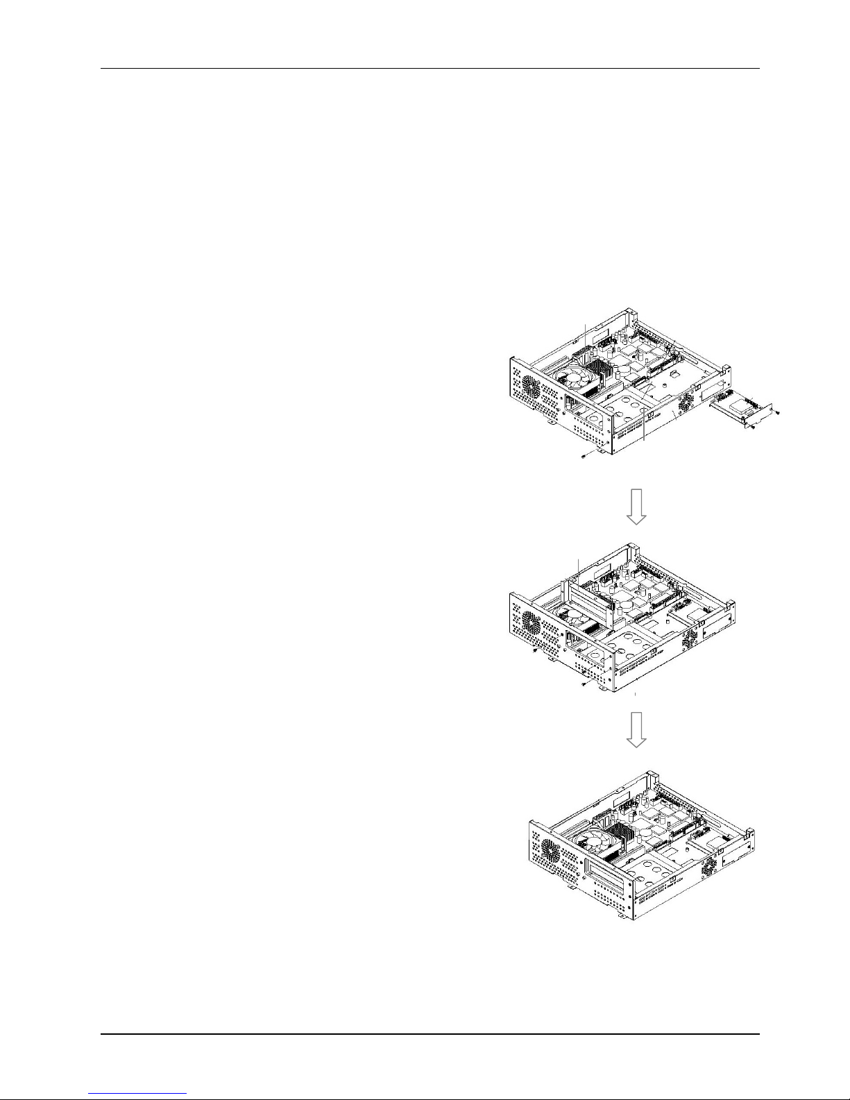
Service
Manual version
1008
MP1200/MP1500
(PC920 Intel 945G)
5-45
5.2.9.
PC Mo
dule
Integration
The PC
’
s individual
module
s are now ready for final integration to the PC chassis
to make a complete
panel PC
. The sequence for integration is from the
motherboard
,
the HDD module
, the toucshcreen
controller,
the expansion door,
the CD
-R/FDD
module, the display module, the
inverter
,
the
power
supply,
the
riser card
and then followed by the
PC cover
module.
Follow the steps below to
integrate
the
individual modules
to the system chassis.
5.2.9.1.
Motherboard
Integration
1.
The
motherboard
(2) i
s th
e first component to be assembled to the
PC
chassis
(A)
. Make sure the
CPU with cooling fan and DDR are already properly installed to the
motherboard
.
From your point
of view,
the expansion opening is at your right sid
e
. Themotherboard
module is to be
installed
to the lower side of the
chassis
.2.Tape the
motherboard
insulator
(1)tothe
chassis
first. The
insulator is to
isolate
the
electronic components on the reverse side of the
motherboard
from the metal compartment to
prevent short circuitry caused
during system
operation.
3.
There are eight screws holes on the
motherboard
.
Retain
the
motherboard
(2)
to the chassis with
eight
PMS M
3*5screws
.
5.2.9.2.
HDD Module Integration
4.
There are two clamps at the bottom
side
used to
hold the HDD module to the ch
assis. I
nsert the
HDD module to the chassis and
clamp
it into place.
Retain
the HDD module
(3)
to the chassis with
one
FMS M3*5 screw
at the upper side of the
chassis.
5.
Connect
the other end
of the
20P*2
HDD
ribbon
cable
to IDE1
at the left upper side of
the
moth
erboard
.
5.2.9.3.
Touchscreen Controller Integration
6.
Insert the touchscreen controller bracket
(4)to the chassis from the opening at the left
upper side opening and retain it to the chassis
with two FMS M3*5 screws.
7.
Connect the other end of the
5P*2
flat cable
f
rom
the controller
to
COM3
at left upper side of
the
motherboard
.8.C
onnect the other end of the 2
P
power
wire
to the
CN1
on the
motherboard
.
5.2.9.4.
Expansion Door Integration
9.
Retain the expansion door
(5)
to the opening at
the right side of
the chassis with thre
e FMS
M3*5
screws.
(4)
FMS 3*5 (2)
(5)
FMS 3*5 (3)
(3)
FMS 3*5 (1)
(2)
PMS 3*5 (8)
Page 54
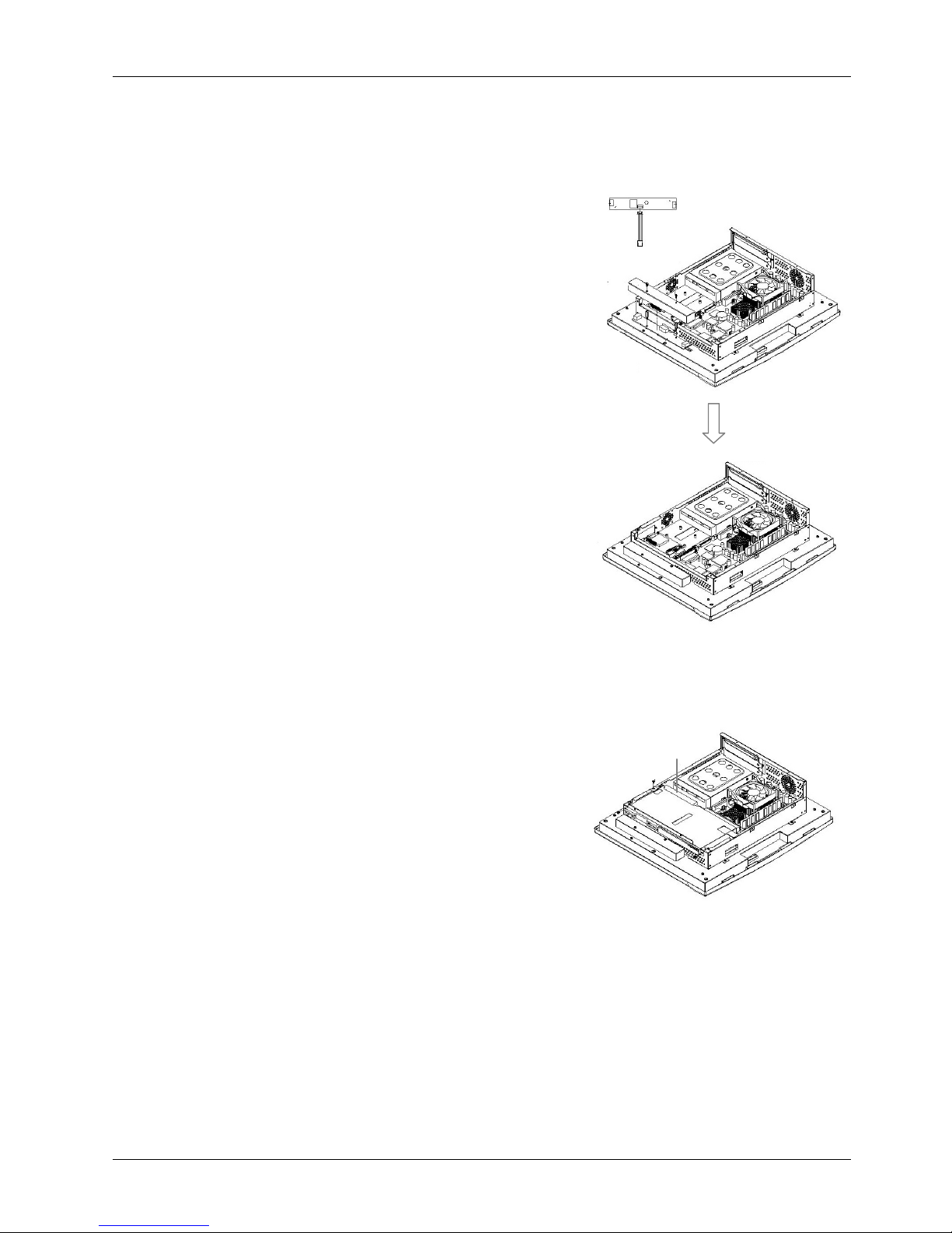
Service
Manual version
1008
MP1200/MP1500
(PC920 Intel 945G)
5-46
5.2.9.5.
Display Module Integration
Due to cabling concern, the display module has to be integrated to the PC module before the
CD-R/FDD
module integration.
7.
Retain
thePCchassis
to the display module
(6)
with six
PMS M3*6 screws.
8.
One end
of the LVDS
cable is already
plugged to the
LCD panel and the other end is to come out from the
small opening at the middle of the LCD holder
. Make
sure th
is
other
end is to go through the rectangle
opening at the rear side of the system chassis
and
have
it connected to LCD connector,
LCD1
on the
motherboard
.9.The touchscreen 5
P white
flat cable should go through
the rectangle opening at the left side of the LCD holder,
then
get into the chassis from the oval
-
shape opening
at the left side of the chassis.
C
onnect this cable to
P4on
the touchcreen controller.
10.The
inverter
cable
for
MP1500
is a7P
to 4Pcable with
wafer connectors at both sides.
Insert
the 7
P
endinto
the left opening of
the
inverter
insulator
and have
it
connected
toCN1
on the
inverter
f
irst.
11.
Connect the
MP1500
’sLCD
pink
-
white
power
wires
from the LCD to
CN2
and
CN3onthe
inverter
.
12.
Retain
MP1500
’sinverter
(7)to
the left side of the
display
module
with two M3*15 bolts.
13.
Insert
the
inverter
cable
to
the chassis through the
small
open
ing
at the left side of
the
chassis
. Connect
the other end of the
inverter
cable to the
motherboard
’s
INV1.
14.
Retain
MP1500
’sinverter
cover
(8)to the
inverter
with
two PMS M3*6 screws.
15.
Connect the other end of the IrDA/SPK cable to
CN4
on
the
motherboard
.
5.2.9.6.
Slim CD
-
R/FDD
Integration
16.The CD
-
R/FDD
module
(9)is to be installed on the left
side of the chassis.
17.
Connect the 40
-
pin end of the CD
-
ROM
ribbon
cable to
the
motherboard
’sIDE2
connector.
18.
There is a 4
-
pin
black & red
CD audio
-inwire
to be
plugged
toCD1
on the
motherboard
. Connect the other
end to the 4
-
pin black pin connector on the CD
-
ROM
board.
19.
Connect the other end of
the FDD cable to the
FDD1
on
the
motherboard
.
20.
Fix the whole unit to the chassis and fix them together with
three
FMSM3*5 screws.
(9)
FMS 3*5 (3)
(7)
M
3*15 bolt (2)
(8)
PMS 3*6 (2)
PMS 3*6 (6)
(6)
Page 55
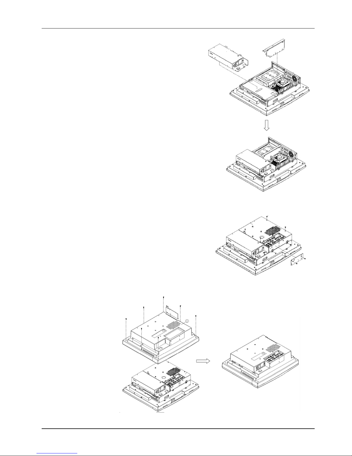
Service
Manual version
1008
MP1200/MP1500
(PC920 Intel 945G)
5-47
(10)
FMS 3*5 (4)
(11)
(12)
FMS 3*5 (9)
(
13)
FMS 3*5 (2)
(14)(15)FMS 3*8 (7)
5.2.9.7.
Power Supply Integration
21.
Integrate the power supply module
(10)
to the
PC’s chassis and retain them together with three
FMS M3*5 screws.
22.
Connect the power switch cable to
CN4on the
motherboard
.
23.
Plug the ATX
10P*2
power cable to the ATX
power connector,
ATXP
1
on the
motherboard
.
24.
Plug the ATX
12V
2P*2
power cable to the
ATX
12V
power connector,
ATXP
2
on the
motherboard
.
25.
Connect the big 4
-
pole
end of the power cable to
the HDD.
26.
Connect the
small
4-pole end of the power cable
to the CD
-
ROM board.
5.2.9.8.
Riser Card I
ntegration
27.Ha
ve the riser card module
(11)
firmly plugged to
the
ESIA slot
on the
motherboard
.
5.2.9.9.
I/O Cover Integration
28.
Plug the I/O module
(12)
to the
IOINF1
slot on the
motherboard
and retain it to the chassis
with
nine
FMSM3*5screw
s.
5.2.9.10.
I/O Cover Integra
tion
29.
Plug the I/O module to the
IOINF1
slot on the
motherboard
and retain it to the chassis
with
nine
FMSM3*5screw
s.
30.
Fix a stand bracket
(13)
at the bottom side of the
chassis
with two FMS M3*5 screws
.
5.2.9.11.
Plastic Cover Integration
31.
Insert the
expansion
do
or plastic
cover (14
) the back cover and
click it into place.
32.
Retain the
rear plastic
cover
(15)
to the whole unit
together with
seven
PMS
M3*8 screws.
Page 56
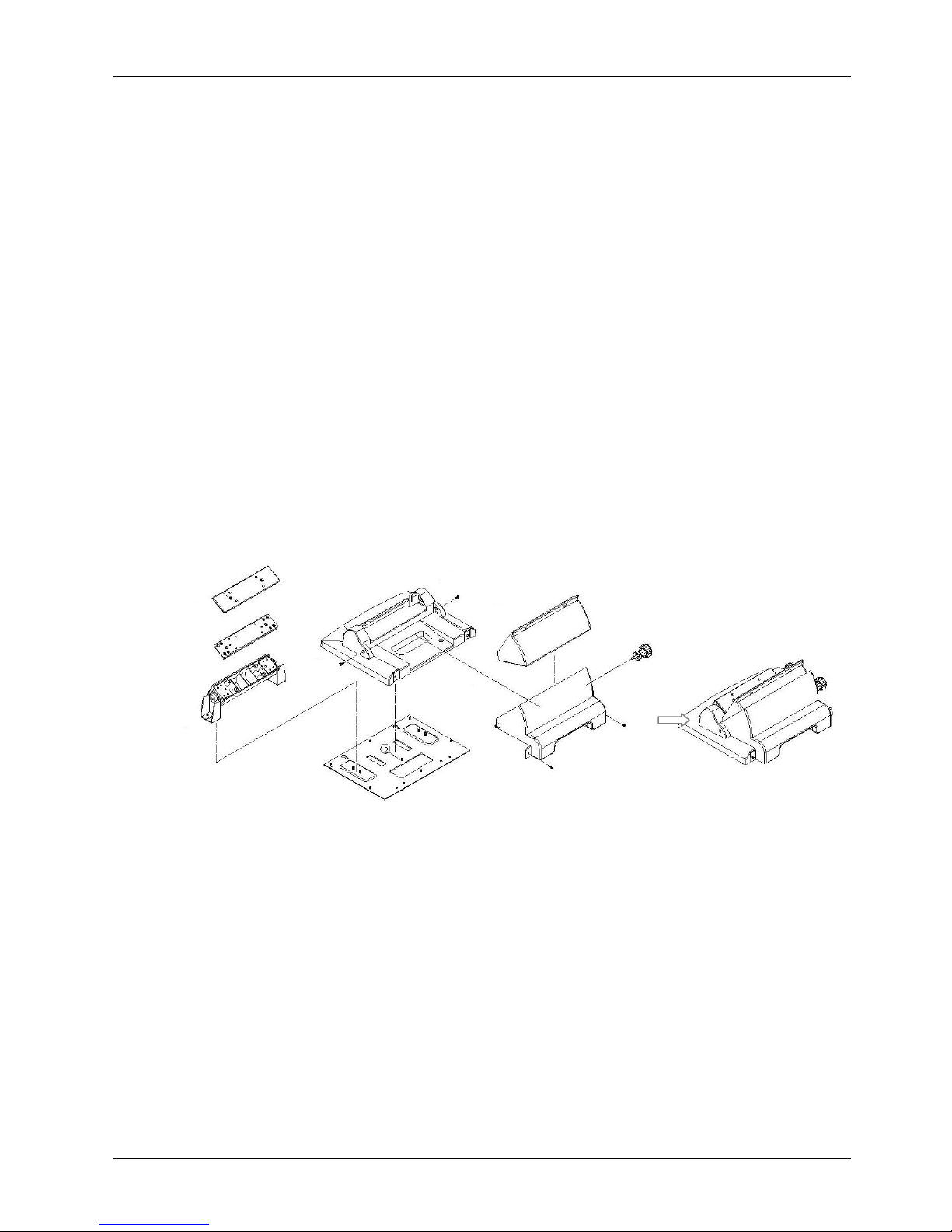
Service
Manual version
1008
MP1200/MP1500
(PC920 Intel 945G)
5-48
5.3.Panel PC
Integration
The
MP1200/MP1500
system comes with a versatile stand composing of one big pede
stal and one set
of cable management covers. The following figure illustrates the steps to make up the stand.
1.
Insert the two hinges (1) to the hinge cover (2).
Please note that the two hinges are different.
The
left
hinge comes with a lock which
istobe
used to fix the hinge knob.
2.
Put a hinge bracket (3) to the top of the two hinges.
Retain the two hinges
(1)
to the
hinge bracket
(3) with
three
FMS M4*8 screws
for each
.3.Retain the hinge bracket (3) to the hinge cover (2) with four FMS 3*5 screws.
4.
Reta
in a plastic
bracket cover (4)
to the hinge set
with two
P
MS M3*6 screws.
5.
Attach
the base module to t
he metal base
plate
(5)
. Retain the metal plate to the hinge set and the
base
cover
with four FMS M4*6 screws
and nine FMS M3*5 screws, respectively
.Note that there
are two avocado
-
shape holes on the metal base. The two avocado holes are used to fix the stand
to the table for special application.
6.
Insert the stand bottom cover (
6
) to the hinge module and fix them together with four
PMSM
3*6
screws.
7.
Retai
n the
stand
upper cover (
7
) to the
base module
to a base
knob
(8).8.Attach rubber pads to the screws at the bottom side of
the
pedestal metal plate (
5
). The rubber
pads are to prevent the metal plate from scratching the table when the panel PC is for desk
top
use.
To assemble the
pedestal
set
to the
panel PC
, simply
retain
them together with four PMS M4*
18
s
crews from the base. Then,
fix the
stand
upper cover (
7
) to the panel PC with two PMS M3*6 screws.
The stand can be tilted from
45 to 90
0
by
swiveling the
base
knob
(8)
and pulling the base up and
down
.
(1)(1)FMS 4*8 (6)
(3)
FMS 3*5 (4)
(2)
PMS 3*6 (2)
(4)
FMS 4*6 (4)
FMS 3*5 (9)
PMS 3*6 (4)
(6)
PMS 3*6 (2)
(7)(8)(5)
Page 57

Service
Manual version
1008
MP1200/MP1500
(PC920 Intel 945G)
6-49
66..SSyysstteemmMMootthheerrbbooaarrdd&&II//OOBBooaarrdds
s
The
system controller used in the
MP1200/MP1500
system
is a special
-
design Intel Celeron
M
/Pentium
M
multimedia
motherboard. All the onboard signal is connec
ted to
the
external I/O ports via two I/O boards
. This chapter
provides jumper definition and connector signal of the
motherboard and the I/O board
s
.
Page 58

Service
Manual version
1008
MP1200/MP1500
(PC920 Intel 945G)
6-50
6.1.
MP1200/MP1500
Motherboard
This section provides background information and detail specification on the
M
P1200/MP1500
system engine, PC
920
. Sections include:
General Information
Specification
Board placement & Dimension
6.1.1.
General Information
ThePC920
is an Intel
C
ore 2 Duo
multimedia
ATX
motherboard
with LCD/VGA controller, Ethernet
100/10, AC97 sound, and
IDE flash disk. By integrating single chip, Intel
945
GM, the PC
920
provides
a high performance/low cost desktop solution.
Highly integrated, the PC
920
can adapt
either an
Intel
Core 2 Duo
CPU. Onboard features include
four serial ports, one multi
–
mode P
arallel ports, a floppy drive controller and a PS/2 keyboard PS/2
mouse interface. The built
-
in high speed PCI IDE controller supports both PIO and ATA 100 mode. Up
to four IDE devices can be connected, including large hard disks, CD
-
ROM drives and other I
DE
devices.
The full PC functionality coupled with its multi
-
I/Os stand ready to accommodate a wide
range of PC peripherals.
Compact in size and with its highly integrated multimedia and networking
functions, the PC
920
is the most powerful PC engine to bui
ld any small footprint all
-in-
one PC system
for integration into any space
-
constricted embedded applications.
Fully configurable and with its modular design, the PC
920
is an ideal platform for any consumer
computing applications where space is a premium.
Page 59
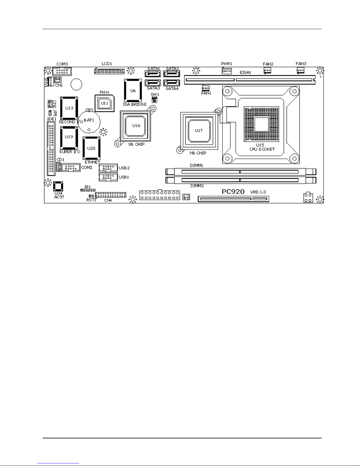
Service
Manual version
1008
MP1200/MP1500
(PC920 Intel 945G)
6-51
6.1.2.
Locating Jumpers & Connectors
The following figure helps you to locate the jumpers and connectors on the motherboard.
Page 60
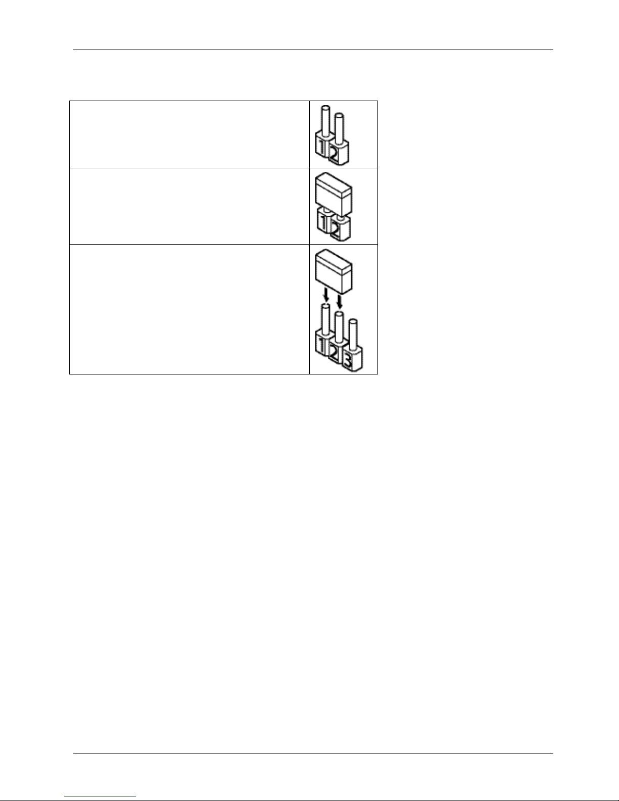
Service
Manual version
1008
MP1200/MP1500
(PC920 Intel 945G)
6-52
6.1.3.
How to Set Jumpers
The jumpers on
the
motherboard
are to set system configuration options. When setting the jumpers
,
be sure the s
hunts (jumper caps) are placed on the correct pins.
This 2
-
pin jumper is
Open
.
This 2
-
pin jumper is
Closed
.
This 3
-
pin jumper is
Closed
on pins 1 and 2.
Page 61
Service
Manual version
1008
MP1200/MP1500
(PC920 Intel 945G)
6-53
6.1.4.
Jumpers & Jumper Setting
The table below lists the function of each jumper. The related jum
per settings are shown in the
coming sections.
Jumper
Description
JP3Clear CMOS
6.1.4.1.
Clear CMOS (JP3)
1-2
Normal
2-3
Clear CMOS
Page 62
Service
Manual version
1008
MP1200/MP1500
(PC920 Intel 945G)
6-54
6.1.5.
Connectors & Pin Assignment
The table below lists the function of each connector on the PC
920
. Their corresponding pin
ass
ignments will be shown in the following sections.
Connector
Description
ATXP1
ATX power connector
ATXP2
ATX +12V power connector
CN1
Power connector for touchscreen
PWR1
Power Output Connector
INV1
LCD Inverter connector
LCD1
LCD connector
USB1,2
USB1&USB2 port connector
IDE1
PATA connector For CD
-
ROM
SATA1~4
SATA1~4 connector
COM2
Serial port 2
COM3
Serial port 3 (for touchscreen)
CD1
CD audio In
IR1
IR/CIR connector
CN4
KB/Mouse/Speaker/LED connector
EISA1
PCI/ISA expansion slot
IOINF1
I
/O slot
FAN1
CPU FAN connector
FAN2/FAN3
System FAN connector
CN3
ATX power ON Switch
RST1
Reset connector
CN2
EXT. LAN wake up connector
Page 63
Service
Manual version
1008
MP1200/MP1500
(PC920 Intel 945G)
6-55
6.1.5.1.
ATXP1: ATX Power Connector
ATXP1 is a standard ATX power connector. This connector is provided to conn
ect to an ATX power
supply. The plug of the power supply will only insert in one orientation due to the different hole size.
Find the proper orientation and push down the power connector firmly to make sure the pins are
aligned. Its pin assignments are l
isted below
:
Pin #
Signal
Pin #
Signal
3.3V
11
3.3V
2
3.3V
12-12V
3
Gnd13Gnd
4
+5V
14
PSON#
5
Gnd15Gnd6+5V
16
Gnd7Gnd17Gnd8PWROK
18-5V9SB5V
19
+5V
10
+12V
20
+5V
6.1.5.2.
ATXP
2
: ATX +12V Power
C
onnector
ATXP2 is a standard +12V ATX powe
r connector. Its pin assignments are listed below
Pin #
Signal
Pin #
Signal
1
GND
3
+12V
2
GND
4
+12V
6.1.5.3.
CN1: Touchscreen
Power Connector
Pin #
Signal
1
GND
2
VCC
6.1.5.4.
PWR1: Power
Output
Connector
Pin #
Signal
1
+12V
GND
GND
2
VCC
6.1.5.5.
INV1:
LCD Inver
ter Connector
Pin #
Signal
1
Backlight ADJ
2
GND
3
Backlight Enable
4
12V
Page 64
Service
Manual version
1008
MP1200/MP1500
(PC920 Intel 945G)
6-56
6.1.5.6.
USB1
,2
: USB Port Connector
Pin #
Signal
Pin #
Signal
1
USB VCC
2
USB VCC
3
USB P4
-4USB P5
-5USB P4+
6
USB P5+
7
GND
8
GND
9
KEY10HEAD#
6.1.5.7.
LCD1
: LCD Connector
Pin #
Signal
Pin #
Signal
1
YA0M
2
YA0P
3
YA1M
4
YA1P
5
YA2M
6
YA2P
7
GND
8
CLKAM
9
CLKAP
10
YA3M
11
YA3P
12
YB0M
13
YB0P
14
GND
15
YB1M
16
YB1P
17
GND
18
YB2M
19
YB2P
20
CLKBM
21
CLKBP
22
YB3M
23
YB3P
24
GND
25
VCC3
26
VCC3
27
VCC3
28
VCC29VCC30VCC
Page 65
Service
Manual version
1008
MP1200/MP1500
(PC920 Intel 945G)
6-57
6.1.5.8.
IDE1:
PATA Connector for CD
-
ROM
The PC920 provides one sets of 40
-
pin IDE connectors. The built
-
in high speed PCI IDE controller
supports both PIO and ATA 100 mode. Up to two IDE devices can be connected, including large hard
disks, CD
-
ROM drive
s and ATAPI devices. Their corresponding pin assignments are listed below
:
Pin #
Signal
Pin #
Signal
1
RESET#
2
GND
3
DATA 7
4
DATA 8
5
DATA 6
6
DATA 9
7
DATA 5
8
DATA10
9
DATA 4
10
DATA11
11
DATA 3
12
DATA12
13
DATA 2
14
DATA13
15
DATA 1
16
DATA
1417DATA 0
18
DATA15
19
GND
20NC21
IDEREQ
22
GND
23
IOW#
24
GND
25
IOR#
26
GND
27
ICHRDY#
28
GND
29
DACK
30
GND
31
IDEIRQ
32NC33A134
LID35A036A237IDECS0
38
IDECS1
39
HDD LED
40
GND
6.1.5.9.
SATA1~4 : SATA Connector
The PC920 has an integ
rated SATA host controller that supports independent DMA operation on four
ports and supports data transfer rat
es of up to 3.0Gb/s (300 MB/s). Their corresponding pin
assignments are listed below
:
Pin #
Signal
1
GND
2
TXP3TXN4GND
5
RXP
6
RXN
7
GND
Page 66
Service
Manual version
1008
MP1200/MP1500
(PC920 Intel 945G)
6-58
6.1.5.10.
COM2
COM2
is a RS
-
232, 422 or 485, selected via BIOS setup.
Pin #
Signal
Pin #
Signal
1
DCD
/422TX
-2DSR
3
RXD
/422TX+
4
RTS5TXD
/422RX+
6
CTS7DTR
/422RX
-8RI9GND
10
KEY
6.1.5.11.
COM3
COM 3 is an internal RS
-
232 reserved for touchscreen. Its corresponding pin assignment is listed as
below;
Pin #
Signal
Pin #
Signal
1
DCD
2
DSR
3
RXD
4
RTS5TXD6CTS7DTR8RI9GND
10
VCC
6.1.5.12.
CD1: CD Audio IN
Pin #
Signal
1
Left channel
2
CD GND
3
CD GND
4
Right channel
6.1.5.13.
IR: IR
/CIR
Connector
IR
Pin #
Signal
15V2NC3
IRRX
4
GND
5
IRTX
6
CIRRX
Page 67
Service
Manual version
1008
MP1200/MP1500
(PC920 Intel 945G)
6-59
6.1.5.14.
CN4: Power LED &
EXT.
KB
/MS, USB
Pin #
Signal
Pi
n #
Signal
1
VCC2VCC3HDD LED
4
LAN LED
5
Suspend LED
6
IRTX
7
KEY8IRRX
9
BACKLIGHT CTRL INPUT
10
CIRRX (Option)
11
GND
12
GND
13
SPK-LO14SPK-RO15SPK-LN16SPK-RN17GND
18
GND
19
USB P2
-20EXT.KBDAT
21
USB P2+
22
EXT.KBCLK
23
USB P3
-24EXT.MSDAT
25
USB P3+
26
EXT.MSCLK
6.1.5.15.
IOINF 1:
I/O Connector
The PC920’s onboard I/O signal for LAN, USB, keyboard, mouse, VGA, COM ports and parallel port are
all mixed in the IOINF1 slot. By plugging an IO
-
005 I/O board and connected to another IO
-
006
I/O
board, all the onboard signal are connected to the system external I/O ports. Please be noted that the
IOINF1 is a slot in AGP slot form, but it is not to be plugged with any AGP card.
Page 68
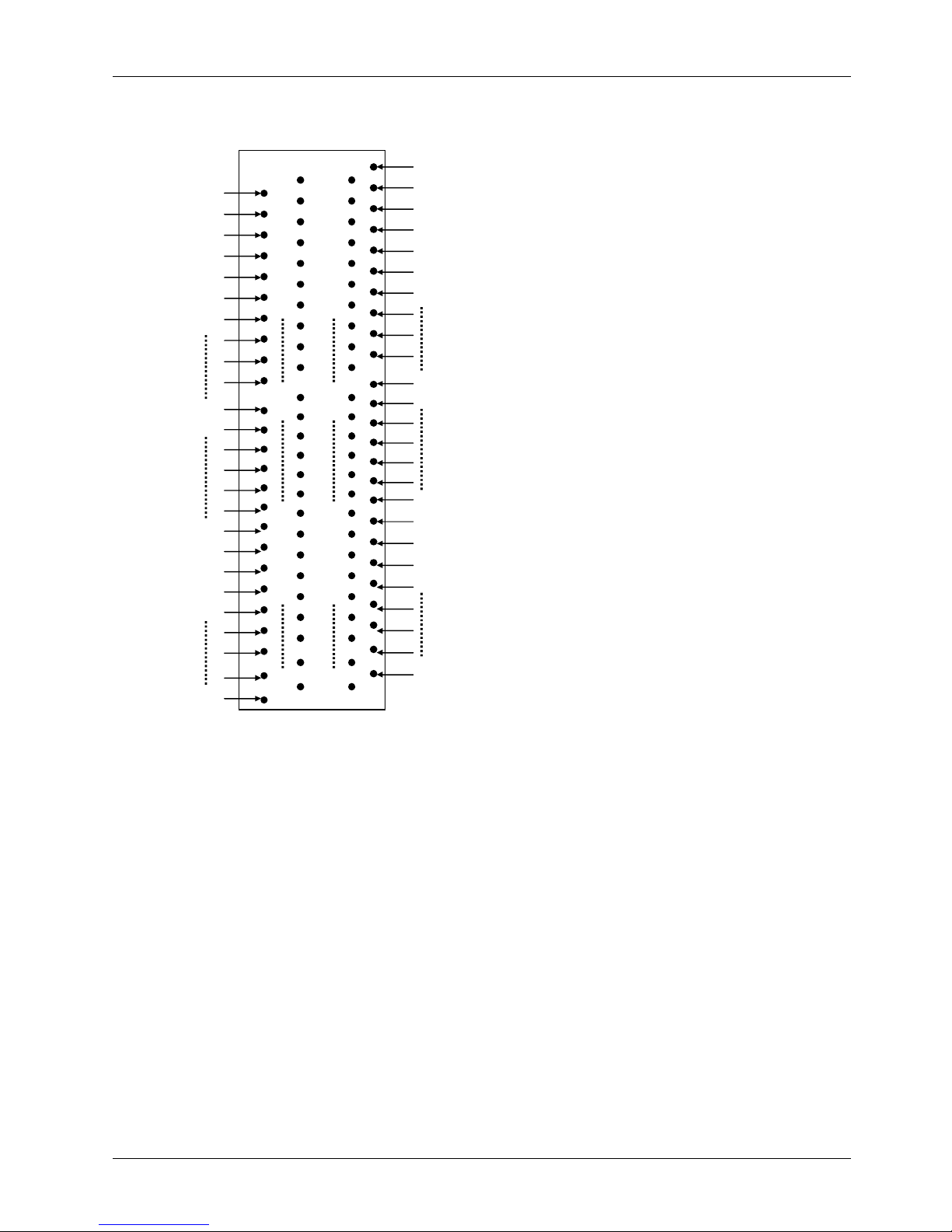
Service
Manual version
1008
MP1200/MP1500
(PC920 Intel 945G)
6-60
6.1.5.16.
EISA1:
PCI/ISA Expansion Slot
The PC
920
provides an ISA/PCI slo
t for ISA and PCI device expansion.
B1B2B3B4B5B6B7
B31D1D2D3D4
D18E1E2E3E4E5E6
E7
E31
G1
G2G3G4
G19
A1A2A3A4A5A6A7
A31
C1C2C3C4C18F1F2
F3F4F5F6F7
F31H1H2
H3
H4
H19
EISA1:
PCI/ISA Slot Side View
Page 69

Service
Manual version
1008
MP1200/MP1500
(PC920 Intel 945G)
6-61
EISA1:
PCI/ISA Slot Connector Pin Assignment
Pin
Signal
Pin
Signal
Pin
Signal
Pin
Signal
F1
GND
B1
GND
E1
GND
A1
IOCHK
F2
GND
B2
ISARST
E2
GND
A2
SD7F3INTB
B3
VCCE3INTC
A3
SD6F4INTA
B4
IRQ9
E4
INTD
A4
SD5F5
VCCB5-5VE5
VCCA5SD4F6KEYB6DRQ2
E6
KEYA6SD3F7VCCB7-
12VE7VCCA7SD2F8PCICLK1
B8
OWS
E8
PCIRST
A8
SD1F9GND
B9
+12V
E9
GNT0
A9
SD0
F10
GNT3
B10
GND
E10
REQ0
A10
IORDY
F11
GND
B11
SMEMW
E11
GND
A11
AEN
F12
REQ3
B12
SMEMR
E12
PCILKE
2
A12
SA19
F13
AD31
B13
IOW
E13
GND
A13
SA18
F14
AD29
B14
IOR
E14
AD30
A14
SA17
F15NCB15
DACK3
E15NCA15
SA16
F16
KEY
B16
DRQ3
E16
KEY
A16
SA15
F17NCB17
DACK1
E17NCA17
SA14
F18
AD27
B18
DRQ1
E18
AD28
A18
SA13
F19
AD25
B19
REF
E19
AD26
A19
SA12F20
CBE3
B20
ATCLK
E20
AD24
A20
SA11
F21
AD23
B21
IRQ7
E21
AD22
A21
SA10
F22
AD21
B22
IRQ6
E22
AD20
A22
SA9
F23
AD19
B23
IRQ5
E23
AD18
A23
SA8
F24NCB24
IRQ4
E24NCA24
SA7
F25
KEY
B25
IRQ3
E25
KEY
A25
SA6
F26NCB26
DACK2
E26NCA26
SA5
F27
AD17B27TCE27
AD16
A27
SA4
F28
IRDY
B28
ALE
E28
FRAME
A28
SA3
F29
DEVSEL
B29
VCC
E29
CBE2
A29
SA2
F30
LOCK
B30
OSC
E30
TRDY
A30
SA1
F31
PERR
B31
GND
E31
STOP
A31
SA0H1SERR
D1
MEMCS16
G1NCC1
SBHE
H2
AD15
D2
IOCS16
G2NCC2
LA23
H3
AD14
D3
IRQ10
G3
CBE1
C3
LA22
H4
AD12
D4
IRQ11
G4
PARC4LA21
H5
GND
D5
IRQ12
G5
GND
C5
LA20
H6
KEYD6IRQ15
G6
KEYC6LA19
H7
GND
D7
IRQ14
G7
GND
C7
LA18
H8
AD10
D8
DACK0
G8
AD13
C8
LA17
H9
AD8D9DRQ0
G9
AD11
C9
MEMR
H10
AD7
D10
DACK5
G10
AD9
C10
MEMW
H11
AD5D11
DRQ5
G11
CBE0
C11
SD8
H12
AD3
D12
DACK6
G12
AD6
C12
SD9
H13
AD1
D13
DRQ6
G13
AD4
C13
SD10
Page 70
Service
Manual version
1008
MP1200/MP1500
(PC920 Intel 945G)
6-62
H14
AD0
D14
DACK7
G14
AD2
C14
SD11
H15
KEY
D15
DRQ7
G15
KEY
C15
SD12
H16
VCC
D16
VCC
G16
VCC
C16
SD13
H17
VCC
D17
MASTER
G17
VCC
C17
SD14
H18
GND
D18
GND
G18
GND
C18
SD15
H19
GND
G19
GND
6.1.5.17.
FAN 1~3: FAN
Connector
Pin #
Signal
1
GND
2
+12V
3
FAN SPEED DECE
CT
6.1.5.18.
CN3: ATX Power on Switch
Pin #
Signal
1
5VSB
2
Power ON/OFF
6.1.5.19.
RST1: Reset System Connector
Pin #
Signal
1
RESET
2
GND
6.1.5.20.
CN2:
External LAN Wake
-
up
Pin #
Signal
1
5VSB
2
GND
3
LAN WAKE
-
UP
Page 71
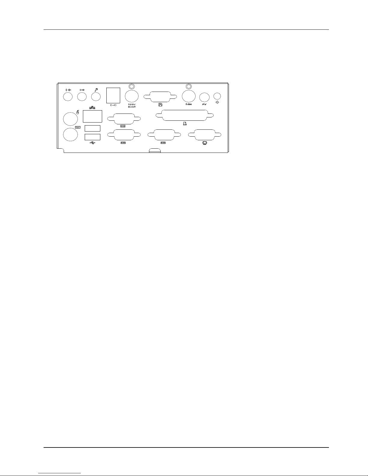
Service
Manual version
1008
MP1200/MP1500
(PC920 Intel 945G)
6-63
6.2.
MP1200/MP1500
I/O Board
s
TheIO-
005
andIO-
006
are two
docking boards used to connect all
of
the I/O signal from
MP1200/MP1500
’sMotherboard
to the exterior of the system
for external device connection. Thi
s
section provides jumper definition and connector signal of the
two
I/O board
s
.
421
Page 72
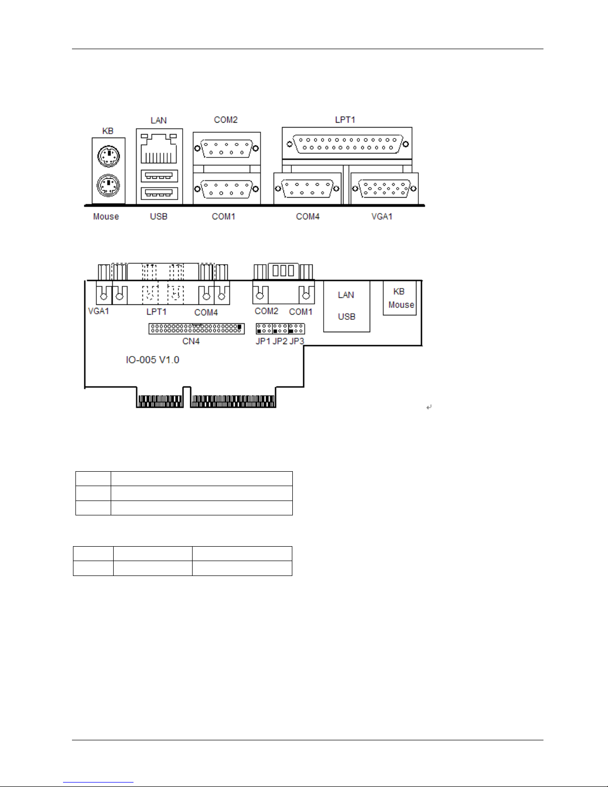
Service
Manual version
1008
MP1200/MP1500
(PC920 Intel 945G)
6-64
6.2.1.
I/O Board
IO-005
The IO
-
005 connects the onboard keyboard, mouse, Ethernet, USB ports, COM1, COM2, COM4 ,
parallel port and VGA signal from the Motherboard to the sys
tem for external device connection.
6.2.1.1.
Jumpers & Jumper Setting
The table below lists the function of each jumper on IO
-
005.
JP3COM1 pin 9 power selection
JP2COM2 pin 9 power selection
JP1COM4 pin 9 power selection
The
MP1200/MP1500
onboard COM p
ort power selection is selected via
jump
ersetting
RI5V12V1-23-45-
6
6.2.1.2.
CN4: EXT. Connector
The onboard speaker
-
out, line
-
in, MIC
-
in, DIO and external FDD are connected to the CN4 on IO
-
005.
Then, via a 44
-
pin flat cable, these signals are linked to I
O-006 for external device connection.
Page 73
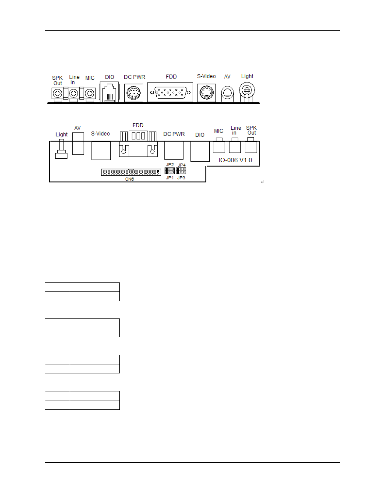
Service
Manual version
1008
MP1200/MP1500
(PC920 Intel 945G)
6-65
6.2.2.
IO
Board
-
IO006
TheIO-
006
is an I/O board links the onboard speaker
-
out, line
-
in, MIC
-
in, DIO and external FDD
from Io
-
005 to the system for external device connection.
6.2.2.1.
Jumpers & Jumper Setting
CN
4 DIO port
:
The DIO port address setting is selected in CMOS SETTING. Select ADDRES 200H OR
208H
Read DIO IN BIT0~BIT3 IN DIO PORT ADDRES BIT0~3
WRITE DIO OUT BIT0~3 IN DIO PORT ADDRES BIT4~7
JP2: CN4 DIO port pin#2 select
1-2
DIO IN Bit 0
2-3
DIO OUT B
it 2
JP1: CN4 DIO port pin#3 select
1-2
DIO IN Bit 1
2-3
DIO OUT Bit 3
JP4: CN4 DIO port pin#5 select
1-2
DIO OUT Bit 0
2-3
DIO IN Bit 2
JP2: CN4 DIO port pin#6 select
1-2
DIO OUT Bit 1
2-3
DIO IN Bit 3
6.2.2.2.
CN6: EXT. Connector
CN6 is a 44
-
pin connec
tor links the onboard speaker
-
out, line
-
in, MIC
-
in, DIO and external FDD to the
IO-006 for external device connection.
Page 74

Service
Manual version
1008
MP1200/MP1500
(PC920 Intel 945G)
6-66
Page 75

Service
Manual version
1008
MP1200/MP1500
(PC920 Intel 945G)
6-67
6.2.3.
Connectors & Pin Assignment
The table below lists the function of each connector on
IO-005 and IO
-
006
. Their corresponding pin
assign
ments will be shown in the following sections.
Keyboard
Keyboard connector
Mouse
Mouse connector
COM1
Serial port 1 (3F8)
COM2
Serial port 2 (2F8)
COM4
Serial port 4 (2E8)
DC Power
DC power +5V/+12VC output
LPT
Parallel port
CRT
CRT display connecto
r
FDD
External FDD connector
USB1
USB connector 1
USB2
USB connector 2
DIO
Digital I/O connector
LAN
Ethernet connector
MIC-in
Microphone
-
in connector
Line-in
Line-in connector
SPK-out
Speaker output connector
VR
LCD Backlight control
Page 76
Service
Manual version
1008
MP1200/MP1500
(PC920 Intel 945G)
6-68
6.2.3.1.
Keyboard
:
PS/2 KB Connector
Pin #
Signal
1
KBDATA
2NC3
GND
4
SB5V
5
KBCLK
6
NC
6.2.3.2.
Mouse
: PS/2 Mouse
Pin #
Signal
1
MSDATA
2NC3
GND
4
5V
5
MSCLK
6
NC
6.2.3.3.
COM1, COM2, COM4
(DB-9)
Pin #
Signal
Pin #
Signal
1
DCD
6
DSR
2
RXD
7
RTS3TXD8CTS4DTR9RI (+5V/12V)
5
GND
6.2.3.4.
DC Power
: DC Power Output
Pin #
Signal
Pin #
Signal
1
GND
5
+5V
2
GND
6
+12V
3
+5V
7
GND
4
+12V
8
GND
6.2.3.5.
LPT1: D
-
SUB-25 Parallel Port
Pin #
Signal
Pin #
Signal
1
STRB#
14
AFD#
2
DATA 0
15
ERROR#
3
DATA 1
16
INIT#
4
DATA 2
17
SLINT#
5
DATA 3
18
GND
6
DATA 4
19
GND
7
DATA 5
20
GND
8
DATA 6
21
GND
9
DATA 7
22
GND
10
ACK#
23
GND
11
BUSY
24
GND
12PE25
GND
13
SLCT
Page 77
Service
Manual version
1008
MP1200/MP1500
(PC920 Intel 945G)
6-69
6.2.3.6.
CRT: VGA (D
-
SUB 15 Pin)
Pin #
Signal
Pin #
Signal
Pin #
Signal
1
Red6GND
11NC2
Green
7
GND
12
DDCD
ATA3Blue
8
GND
13
Hsync
4NC9NC14
Vsync
5
GND
10
GND
15
DDCCLK
6.2.3.7.
FDD: External FDD Connector
Pin #
Signal
Pin #
Signal
Pin #
Signal
1
RWC#
6
WP#
11
RDATA#
2
INDEX#
7
TRAK0#
12
HEAD#
3
MOA#
8
WE#
13
DSKCHG#
4
DSA#
9
WD#
14
GND
5
DIR#
10
STEP#
15GND
6.2.3.8.
J11: USB 1, USB2 Connector
USB1
USB2
Pin #
Signal
Pin #
Signal
1
USBVCC
1
USBVCC
2
Data
-2Data
-3Data+
3
Data+
4GND4G
ND
6.2.3.9.
DIO1: RJ
-
11 Connector
Pin #
Signal
Pin #
Signal
1
+12V
2
IN_0
/OUT_2
3
IN_1
/OUT_3
4
GND
5
OUT_0
/IN_2
6
OUT
_1
/IN_3
6.2.3.10.
LAN1: RJ
-
45 Ethernet Connector
Pin #
Signal
Pin #
Signal
1
TD+
2TD-3RO+
4NC5NC6RO-7NC8NC
6.2.3.11.
MIC1
Pin #
Signal
1
Vref2NC3NC4MIC IN
5
GND
Page 78

Service
Manual version
1008
MP1200/MP1500
(PC920 Intel 945G)
6-70
6.2.3.12.
LINE 1
Pin #
Signal
1
Right CHI
2NC3NC4
Left CH
5
GND
6.2.3.13.
SPK 1
Pin #
Signal
1
Right CHI
2NC3NC4
Left CH
5
GND
Page 79

Service
Manual version
1008
MP1200/MP1500
(PC920 Intel 945G)
7-71
Page 80

Service
Manual version
1008
MP1200/MP1500
(PC920 Intel 945G)
7-72
77..BBIIOOSSSSeettuuppUUttiilliitty
y
The BIOS (Basic Input and Output System) Setup Utility displays
the system's configuration status and provides options to set
system parameters. The parameters are stored in
battery
-
backed
-
up CMOS RAM that saves this information even
when the power is turned off. When the system is turned back on,
the system is configured with the values found in CMOS. This
chapter describes how to set up BIOS configuration.
Page 81

Service
Manual version
1008
MP1200/MP1500
(PC920 Intel 945G)
7-73
7.1.
About the BIOS S
etup Utility
The BIOS Setup Utility enables you to configure the following items
:
Hard drives, diskette drives, and peripherals
Video display type and display options
Password protection from unauthorized use
Power management features
This Setup Utility
should be used for the following
:
The system is staring for the first time.
The hardware devices attached to the systems have been changed
The CMOS memory has lost power and the configuration information has been erased.
When a configuration error is detec
ted and you are prompted to make changes to the Setup
Utility
When trying to resolve IRQ conflicts
When making changes to the Power Management configuration
When changing the User or Supervisor password
The BIOS setup program is stored in ROM, which can b
e accessed by pressing <DEL> key on the
keyboard immediately when the system is powered on.
In order to retain the specified setup information when the system power is turned off, the system
setup information is stored in a battery
-
backed CMOS RAM. The b
attery is to ensure the settings will
not be erased when the computer is turned off or reset. When the computer is powered on again, the
system will read the settings stored in the CMOS RAM and compare them to the equipment check
conducted during the powe
r on self test (POST). If any error or mismatch occurs, an error message
will be shown on the screen and the computer will be prompted to run the setup program.
Page 82
Service
Manual version
1008
MP1200/MP1500
(PC920 Intel 945G)
7-74
7.2.
Control Key Definition
The BIOS navigation keys are listed below.
Move to previous item
Move to next item
Move to the item in the left hand
Move to the item in the right hand
Esc
Main Menu
-
Quit and not save changes into CMOS
Status Page Setup Menu and Option Page Setup Menu
-
Exit current page and return to Main Menu
PgUp
Increase the numeric value or make changes
PgDn
Decrease the numeric value or make changes
F1
General help, only for Status Page Setup Menu and
Option P
age Setup Menu
F5
Restore the previous CMOS value from CMOS, only for
Option Page Setup Menu
F6
Load the default CMOS value from BIOS default table,
only for Option Page Setup Menu
F7
Load the default
F10
Save all the CMOS changes, only for Main Menu
Page 83

Service
Manual version
1008
MP1200/MP1500
(PC920 Intel 945G)
7-75
7.3.
Getting Help
7.3.1.
Main Menu
The on
-
line description of the highlighted setup function is displayed at the bottom of the screen.
Press <F1> to pop up a small help window that describes the appropriate keys to use and the possible
selections for the highlighte
d item. To exit the Help Window, press <ESC>.
7.4.
AWARD BIOS Setup
7.4.1.
Entering the Setup Utility
When you power on the system, BIOS enters the Power
-
On Self Test (POST) routines. POST is a series
of built
-
in diagnostics performed by the BIOS. After the POST rout
ines are completed, the following
message appears
:
Press DEL to enter SETUP
Press the delete key <Delete> to access the Award BIOS Setup Utility. The setup main menu will
appear on the screen. The main menu of the Setup Utility displays a list of the options that are
available. A highlight indicates whi
ch option is currently selected. Use the cursor arrow keys to move
the highlight to other options. When an option is highlighted, execute the option by pressing <Enter>.
Some options lead to pop
-
up dialog boxes that prompt you to verify that you wish to e
xecute that
option. Other options lead to dialog boxes that prompt you for information.
Some options (marked with a triangle
) lead to submenus that enable you to change the values for
the option. Use the cursor arrow keys to scroll through the items in
the submenu.
Phoenix
–
Awa
rdBIOS CMOS Setup Utility
Standard CMOS Feature
Frequency/Voltage Control
Advanced BOIS Features
Load Fail
-
Safe Defaults
Advanced Chipset Features
Load Optimized Defaults
Integrated Peripherals
Set Supervisor Password
Power Management Setu
p
Set User Password
PnP/PCI Configuration
Save & Exit Setup
PC Health Status
Exit Without Saving
Esc:Quit
↑↓→
←
:
Select Item
F10:Save & Exit Setup
Page 84

Service
Manual version
1008
MP1200/MP1500
(PC920 Intel 945G)
7-76
The following lists the functions of the items on the BIOS main menu.
Standard CMOS Setup
:
This setup page includes all the items in standard compatible BIOS.
Advanced BIOS Features
:
This setup page includes all
the items of Award special enhanced
features.
Advanced Chipset Features
:
This setup page includes all the items of the chipset special
features.
Integrated Peripherals
:
This setup page includes all onboard peripherals.
Power Management Setup
:
This setup p
age includes all the items of Green function features.
PnP/PCI Configuration
:
This setup page includes all the configurations of PCI & PnP ISA
resources.
PC Health Status
:
This setup page auto detects the temperature, voltage and fan speed.
Frequency/Volta
ge Contro
l:This setup page includes the CPU/DDR/PCI frequency setting.
Load Fail
-
Safe Defaults
:
BIOS Defaults indicates the most appropriate value of the system
parameters that the system would be in safe configuration.
Load Optimized Defaults
:
Setup Defa
ults indicates the value of the system parameters that
the system would be in the best performance configuration.
Set Supervisor Password
:
The supervisor’s password can be set or changed or disabled in this
setup page. It allows you to limit access to the
system and setup, or just to setup.
Set User Password
:
The user’s password can be set or changed or disabled in this setup page.
It allows you to limit access to the system and setup, or just to setup.
Save & Exit Setup
:
Save CMOS value settings to CMOS an
d exit setup.
Exit without Saving
:
Abandon all CMOS value changes and exit setup.
Page 85
Service
Manual version
1008
MP1200/MP1500
(PC920 Intel 945G)
7-77
7.4.2.
Standard CMOS Features
Selecting
Standard CMOS Features
on the main menu displays the following menu. This menu
allows the user to configure the system components such a
s date, time, hard disk drive, floppy disk
drive and display type.
Date
The
Date
item show the current date held by the system. If you are running a Windows OS, these
items are automatically updated whenever you make changes
to the Windows Date Properties utility.
The date format is <day>, <month>, <date>, <year>.
day
The day, from Sun to Sat, determined by the
BIOS and is display
-
only
month
The month, Jan. through Dec.
date
The date, from 1 to 31 (or the maximum
allowed i
n the month)
year
The year, from 1994 through 2079
Time
The
Time
item show the current time held system. If you are running a Windows OS, these items are
automatically updated whenever you make changes to the Windows Time Properties utility.
The times fo
rmat in <hour> <minute> <second>. The time is calculated base on the 24
-
hour
military
-
time clock. For example, 1 p.m. is 13
:00:
00.
Phoen
ix–AwardBIOS CMOS Setup Utility
Standard CMOS Features
Date (mm
:dd:
yy) Web, Feb 23
2
005
Item Help
Time (hh
:
mm
:
ss) 11
:7:
48
Menu Level
IDEPrimary Master [None]
Press [Enter] to enter
next page
for detail
hard drive setting
s
IDEPrimary Slave [None]
IDESecondary Master
[None]
IDESecondary Slave
[None]
Video
[EGA/VGA]
Halt on
[All , But Keyboard]
Panel Number [SettingBy H/W]
Base Memory 640K
Extended Memory 490496K
Total Memory
491520K
↑↓→
Move Enter
:
Select +/
-
/PU/PD
:
Value F10
:
Save ESC
:
Exit F1
:
General Help
Page 86
Service
Manual version
1008
MP1200/MP1500
(PC920 Intel 945G)
7-78
Primary HDDs/Secondary HDDs
This field is used to configure the IDE hard drive installed in the system. Move the cursor to highlight
the IDE Primary/Secondary Master/Slave fields and press <Enter>. The IDE Primary Master submenu
opens
:
IDE HDD Aut
o-Detection
Press <
Enter
> while this item is highlighted if you want the Setup Utility to automatically detect and
configure a hard disk drive on the IDE channel.
IDE Primary/Secondary Master/Slave
If you leave this item at Auto, the system will automatic
ally detect and configure any IDE devices it
finds. If it fails to find a hard disk, change the value to Manual and then manually configure the drive
by entering the characteristics of the drive in the fields described below
:
Capacity
–
displays the capacity of the HDD in megabytes (MB).
Cylinder
–
indicates the number of cylinders that the HDD has. A cylinder is the sum total
of all tracks that are in the same location on every disk surface.
Head
–
displays the number of he
ads in the HDD. A head is a device that reads and writes
data on the hard disk.
Precomp
–
displays the track where precompensation is initiated. Precompensation is a
feature whereby the HDD uses a stronger magnetic field to write data in sectors that are
c
loser to the center of the disk. In CAV recording, in which the disk spins at a constant speed,
the sectors closest to the spindle are packed tighter than the outer sectors.
Landing Zone
–
displays the location of the safe non
-
data area on a hard disk that
is used
for parking the read/write head.
Sector
–
displays the number of sectors available on the HDD. A sector is the smallest unit
of storage space on a disk.
If no hard disk is installed, select NONE and press <Enter>.
Drive A type/Drive B type
The ite
m identifies the types of floppy disk drive A or drive B that has been installed in the computer.
None
No floppy drive installed
360K, 5.25"
5.25 inch PC
-
type standard drive; 360K byte
1.2M, 5.25"
5.25 inch AT
-
type high
-
density drive; 1.2M
bytes (3.5
inch when 3 Mode is Enabled).
720K, 3.5"
3.5 inch double
-
sided drive; 720K byte
1.44M, 3.5"
3.5 inch double
-
sided drive; 1.44M byte
2.88M, 3.5"
3.5 inch double
-
sided drive; 2.88M byte
Video
This item defines the video mode of the system. This main b
oard has a built
-
in VGA graphics system;
you must leave this item at the default setting.
Halt on
This item defines the operation of the system POST (Power On Self Test) routine. You can use this
item to select which types of errors in the POST are suffici
ent to halt the system.
Panel Number
The item selects the panel resolution and LVDS interface for single or dual.
Base Memory, Extended Memory and Total Memory
These items are automatically detected by the system at start up time. These are display
-
only fi
elds.
You cannot make changes to these fields.
Base Memory
–
This field displays the amount of conventional memory detected by the
system during boot.
Extended Memory
–
This field displays the amount of extended memory detected by the
system during boot.
Total Memory
–
This field displays the total amount of memory(Baseand Extended) detected by the system during
boot.
Page 87

Service
Manual version
1008
MP1200/MP1500
(PC920 Intel 945G)
7-79
Page 88

Service
Manual version
1008
MP1200/MP1500
(PC920 Intel 945G)
7-80
7.4.3.
Advanced BIOS Features
Selecting Advanced BIOS Features on the main menu displays this following menu.
CPU Feature
Setting the CPU thermal management mode
Hard Disk Boot Priority
Select Hard Disk Boot Device Priority
Virus Warning
When enabled, this item provides protection against viruses that try to write to the boot sector and
partition table of the ha
rd disk drive. You need to disable this item when installing an operating
system. We recommend that you enable anti
-
virus protection as soon as you have installed an
operating system.
Enabled
:
activates automatically when the system boots up causing a war
ning message to appear
when anything attempts to access the boot sector or hard disk partition table.
Disabled
:
no warning message will appear when anything attempts to access the boot sector or hard
disk partition table.
Phoenix
–
AwardBIOS CMOS Setup Utility
Advanced BIOS Features
CPU Feature
[Press Enter]
Item Help
Hard Disk Boot Priority
[Press Enter]
Menu Level
Virus Warning
[Disabled]
Allows you to choose
the VIRUS warning
Feature for I
DE Hard
Disk boot sector
protection. If this
Function is enabled
and
someone attempt
to
write data into this
area , BIOS will show
a
warning message on
screen and alarm beep
CPU L1 & L2 Cache
[Enabled]
CPU L3 Cache
[Enabled]
Quick Power On Self Te
st
[Enabled]
First Boot device
[HDD
-0]Second Boot Device
[CDROM]
Third Boot Device
[USB
-
FDD]
Boot Other Device
[Enabled]
Swap Floppy Device
[Disabled]
Boot Up Floppy Seek
[Disabled]
Boot
U
p NumLock Status
[On]
Gate A20 Option
[Fast
]
Typematic Rate Setting
[Disabled]
x
Typematic Rate (Chars/sec)
6xTypematic Delay (Msec)
250
Security Option
[Setup]
APIC Mode
[Enable]
MPS Version Control
For OS
[1.4]
OS Select For DRAM > 64MB
[Non
-
OS2]
Report No FDD For WIN 95
[No]
Small Logo (EPA) Show
[Disabled]
↑↓→
Move Enter
:
Select +/
-
/PU/PD
:
Value F10
:
Save ESC
:
Exit F1
:
General
Help
Page 89

Service
Manual version
1008
MP1200/MP1500
(PC920 Intel 945G)
7-81
CPU Internal Cache/External Cach
e
All processors that can be installed in this main board use internal level 1 (L1) and external level 2 (L2)
cache memory. These two items speed up memory access. However, it still depends on CPU/chipset
design. Leave this item at the default setting for
better performance.
Enabled
:
enables cache
Disabled
:
disable cache
Quick Power On Self Test
This category speeds up Power on Self Test (POST) after you power up the computer. If it is set to
Enable, BIOS will shorten or skip some check items during POST.
Enabled
:
enables quick POST
Disabled
:
normal POST
First/Second/Third/Boot Device
The BIOS attempts to load the operating system from the devices in the sequence selected in these
items.
Boot Other Device
When enabled, the system searches all other possible locations for an operating
system if it fails to
find one in the devices specified under the First, Second, and Third boot devices.
Swap Floppy Drive
If the system has two floppy drives, you can swap the logical drive name assignments.
The choice
:
Enabled & Disabled.
Boot Up Floppy
Seek
This category seeks disk drives during boot up. Disabling speeds boot up.
The choice
:
Enabled & Disabled.
Boot Up NumLock Status
This item defines if the keyboard Num Lock key is active when the system is started.
Gate A20 Option
This item defines h
ow the system handles legacy software that was written for an earlier generation
of processors. Leave this item at the default setting.
Typematic Rate Setting
If this item is enabled, you can use the following two items to set the typematic rate and the
t
ypematic delay settings for the keyboard.
Typematic Rate (Chars/Sec)
Use this item to define how many characters per second are generated by a held
-
down key.
Typematic Delay (Msec)
Use this item to define how many milliseconds must elapse before a held
-down key begins generating
repeat characters.
Security Option
If you have installed password protection, this item defines if the password is required at system start
up, or if it is only required when a user tries to enter the Setup Utility.
APIC Mode
Ena
ble or Disable APIC(Advanced Programmable Interrupt Controller) mode
MPS Version Control For OS
This option is only valid for multiprocessor motherboards as it specifies the version of the
Multiprocessor Specification (MPS) that the motherboard will use.
The MPS is a specification by which
PC manufacturers design and build Intel architecture systems with two or more processors.
MPS version 1.4 added extended configuration tables to improve support for multiple PCI bus
configurations and improve future expa
ndability. It is also required for a secondary PCI bus to work
without the need for a bridge. Newer versions of server operating systems will generally support MPS
Page 90

Service
Manual version
1008
MP1200/MP1500
(PC920 Intel 945G)
7-82
1.4 and as such, you should change the BIOS Setup from the default of 1.1 to 1.4 if your ope
rating
system supports version 1.4. Leave it as 1.1 only if you are running older server OSes.
OS Select For DRAM > 64MB
This item is only required if you have installed more than 64 MB of memory and you are running the
OS/2 operating system. Otherwise, le
ave this item at the default.
Report No FDD For Win 95
If you are using Windows 95/98 without a floppy disk drive, select Enabled to release IRQ6. This is
required to pass Windows 95/98's SCT test. You should also disable the Onboard FDC Controller in the
Integrated Peripherals screen when there's no floppy drive in the system. If you set this feature to
Disabled, the BIOS will not report the missing floppy drive to Win95/98.
Small Logo (EPA)Show
This item determines whether the EPA logo is to appear durin
g boot up.
Page 91

Service
Manual version
1008
MP1200/MP1500
(PC920 Intel 945G)
7-83
7.4.4.
Advanced Chipset Features
Selecting Advanced Chipset Features on the main menu displays this following menu.
This option displays critical timing parameters of the main board. Leave the items on this menu at
their default settings unless you
are very familiar with the technical specifications of the system
hardware. If you change the values incorrectly, you may introduce fatal errors or recurring instability
into the system.
DRAM Timing Selectable
Menu setting the
DRAM time
System BIOS Cacheable
:
Selecting Enabled allows caching of the system BIOS ROM at F0000h
-
FFFFFh, resulting in better
system performance.
However, if any program writes to this memory area, a system error may result.
The options are Enabled or Disabled.
Video BIOS Cacheable
Se
lecting Enabled allows caching of the Video RAM, resulting in better system performance. However,
if any program writes to this memory area, a system error may result.
The options are Enabled or Disabled.
Memory Hole at 15M
-
16M
:
You can reserve this area o
f system memory for ISA adapter ROM. When this area is reserved, it
cannot be cached. The user information of peripherals that need to use this area of system memory
usually discusses their memory requirements.
PEG/OnChip VGA Control
This item is to enable
or disable the onboard VGA function
On-
Chip Frame Buffer Size
This item is to set buffer size
The options are 1M.4M.8M.16M or 32M
DVMT Mode
This item is to select the DVMT mode
Phoenix
–
AwardBIOS CMOS Setup Utility
Advanced
Chipset
Features
DRAM Timing Selectable
[By SPD]
Item Help
x
CAS Latency Time
Auto
Menu Level
xDRAM RAS# to CAS# delay
Auto
x
DRAN RAS# precharge
Auto
x
Precharge delay (tRAS)
Auto
x
System Memory Frequency
Auto
System BIOS Cacheable
[Enabled]
Video BIOS Cacheable
[Disabled]
Memory Hole at 15m
-
16M
[Disabled]
** On
-
Chip VGA Se
tting **
PEG/Onchip VGA Control
[Auto]
On-Chip Frame Buffer Size
[ 8MB]
DVMT Mode
[DVMT]
DVMT/FIXED Memory Size
[128MB]
Boot display
[Auto]
Panel Scaling
[Auto]
↑↓→
Move Enter
:
Select
+/-
/PU/PD
:
Value F10
:
Save ESC
:
Exit F1
:
General
Help
Page 92

Service
Manual version
1008
MP1200/MP1500
(PC920 Intel 945G)
7-84
DVMT/FIXED Memory Size
This item is to set DVMT/FIXED mode memory size
The op
tions are 64MB/128MB/224MB
Boot Display
This item is to select the boot display from VBIOS Default or CRT,LCD
Panel Scaling
This item is to select Panel scaling function
Page 93

Service
Manual version
1008
MP1200/MP1500
(PC920 Intel 945G)
7-85
7.4.5.
Integrated Peripherals
Selecting
Integrated Peripherals
on t
he main menu displays
th
e following
menu
.
This option
defines the operation of peripheral components on the system's input/output ports.
Phoenix
–
AwardBIOS CMOS Setup Utility
Integrated Peripherals
OnChip IDE Devic
e
[Press Enter]
Item Help
OnChip Device
[Press Enter]
Menu Level
SuperIO Device
[Press Enter]
↑↓→
Move Enter : Select
+/-/PU/PD:Value
F10:Save
ESC:Exit
F1 :General Help
F5
: Previous Values
F6 : Fail
-
Safe Default
F7 : Optimized Defaults
Page 94

Service
Manual version
1008
MP1200/MP1500
(PC920 Intel 945G)
7-86
7.4.5.1.
OnChip IDE Device
If the
OnChip IDE Device
option is selected from the
Integrated Peripherals
menu, the scree
n
below will appear.
IDE HDD Block Mode
:
Block mode is also called block transfer, multiple commands, or multiple sector read/write. If your IDE
hard drive supports block mode (most new drives do), select Enabled for automatic
detection of the
optimal number of block read/write per sector the drive can support.
The options are Enabled or Disabled.
IDE DMA transfer access
:
The item is to select the IDE DMA mode
The options are Enabled or Disabled.
On-
Chip Primary & Secondary PCI
/IDE
This option enables you to activate/inactivate the Primary & Secondary IDE channel of the
motherboard's onboard IDE controller. You should leave this enabled if you are using this onboard IDE
channel. Disabling it will prevent the IDE devices attached
to this channel from functioning at all.
IDE Primary Master/Slave PIO
The four IDE PIO (Programmed Input/ Output) fields let you set a PIO mode (0
-
4) for each of the four
IDE devices that the onboard IDE interface supports. Modes 0 through 4 provide succe
ssively
increased performance. In Auto mode, the system automatically determines the best mode for each
device.
The options are Auto, Mode 0, Mode 1, Mode 2, Mode 3 or Mode 4.
Primary Master/Slave UltraDMA
UDMA (Ultra DMA) is a DMA data transfer protocol t
hat utilizes ATA commands and the ATA bus to
allow DMA commands to transfer data at a maximum burst rate of 100MB/s. When you select Auto in
the four IDE UDMA fields (for interface supports), the system automatically determines the optimal
data transfer ra
te for each IDE device.
The options are Auto or Disabled.
On-
Chip Serial ATA
:
Phoenix
–
AwardBIOS CMOS Setup Utility
OnChip IDE Device
IDE HDD Block Mode
[Enabled]
Item Help
IDE DMA transfer access
[Enabled]
Menu
Level
On-
Chip Primary
PCI IDE
[Enabled]
IDE Primary Master PIO
[Auto]
IDE Primary Slave PIO
[Auto]
IDE Primary Master UDMA
[Auto]
IDE Primary Slave UDMA
[Auto]
On-Chip Secondary PCI IDE
[Enabled]
IDE secondary Master PIO
[Auto]
IDE secondary Slave PIO
[Auto]
IDE secondary Master UDMA
[Auto]
IDE secondary Slave UDMA
[Auto]
*** On
-
Chip Serial ATA Aetting ***
On-Chip Serial ATA
[Auto]
SATA PORT Speed Settings
Disable
PATA IDE Mode
Primary
SATA Port
P
1,P3 is Secondary
↑↓→
Move Enter
:
Select +/
-
/PU/PD
:
Value F10
:
Save ESC
:
Exit F1
:
General Help
Page 95

Service
Manual version
1008
MP1200/MP1500
(PC920 Intel 945G)
7-87
The item is to setting the On
-
Chip SATA Function
Page 96

Service
Manual version
1008
MP1200/MP1500
(PC920 Intel 945G)
7-88
7.4.5.2.
OnChip Device
If the
OnChip Device
option is selected from the
Integrated Peripherals
menu, the screen below
will appear.
USB Controller
This function is similar to Assign IRQ For USB. It enables or disables IRQ allocation for the USB
(Universal Serial Bus). Enable this if you are using a USB device. If you disable this while using a USB
device, you may
have problems running that device. However, if you don't use any USB devices, set
the option to Disabled. It will free up an IRQ for other devices to use.
USB 2.0 Controller
This item is for disable/enable EHCI controller only, Support the high speed USB
device.
The options are Enabled or Disabled.
USB Keyboard Support
Select Enabled if your system contains a Universal Serial Bus (USB) controller and you have a USB
keyboard.
The options are Enabled or Disabled.
AC97 Audio
Select Auto to support AC97 Audio
.
The options are AC97 Audio or Disabled.
Flash ROM Write
This item supports the BIOS ROM write Enable/Boot block lock/Disable
Onboard LAN Function
The item can enable or disable the onboard Ethernet controller
Phoenix
–
AwardBIOS CMOS Setup Utility
OnChip Device
USB Controller
[Enabled]
Item Help
USB 2.0 Controller
[Enabled]
Menu Level
USB Keyboard Support
[Auto]
AC97 Audio
[AC97 Audio]
Flash ROM Write
[Enabled]
LAN Control
[Enabled]
↑↓→
Move Enter
:
Select
+/-
/PU/PD
:
Value F10
:
Save ESC
:
Exit F1
:
General
Help
Page 97

Service
Manual version
1008
MP1200/MP1500
(PC920 Intel 945G)
7-89
7.4.5.3.
Super
IO
Device
If the
SuperIO Device
opti
on is selected from the
Integrated Peripherals
menu, the screen below
will appear.
Power On Function
This function allows you to set the method by which your system can be turned on. Normally, it should
be set as Button Only so
that your system will only start up if you use the button/switch on the casing.
Other alternative options including starting up the system using the keyboard (if it supports the
Keyboard 98 standard), a keyboard hot key (for other standard keyboards) or t
he mouse.
KB Power On Password
This item can be used to prompt a password when the system power is resumed by keyboard action.
Hot Key Power On
This item can be used to prompt a hot key when the system power is resumed by keyboard action.
Onboard Serial Po
rt 1/Port 2/Port 3/Port 4
This item is to select an address for the serial ports.
The options are 3F8/2F8/3E8/2E8, Disabled.
Onboard UART 1/ UART 2/ UART 3/ UART 4 IRQ
This item is to select an IRQ for the serial ports.
The options are IRQ4/IRQ3/IRQ10/IRQ
11/IRQ9/IRQ5,
COM2 Selectable type
:
This item is to select the COM2 port type
The options are RS232/RS422/RS485.
Onboard Parallel Port 1
:
This item allows you to determine the onboard parallel port controller’s I/O address and parallel port
mode.
The opti
ons are 378/IRQ7, 278/IRQ5, 3BC/IRQ7, Disable.
The options are SPP, EPP, ECP, ECP+EPP, Normal.
Phoenix
–
AwardBIOS CMOS Setup Utility
SuperIO Device
POWER ON Function
[BUTTON INLY]
Item Help
X
KB Power ON Password
Enter
Menu Level
XHot Key Power ON
Ctrl-F1
Onboard Serial Port 1
[3F8]
Onboard UART 1 IRQ
[IRQ4]
COM2 Selectable Type
[RS232]
On
board Serial Port 2
[2F8]
Onboard UART 2 IRQ
[IRQ3]
Onboard Serial Port 3
[3E8]
Onboard UART 3 IRQ
[IRQ10]
Onboard Serial Port 4
[2E8]
Onboard UART 4 IRQ
[IRQ11]
Serial Port 4 Mode
[Normal]
X
IR Duplex mode
Half
X
Use IR Pins
IR-Rx2T
x2
Onboard Parallel Port 1
[378/IRQ7]
Parallel Port 1 Mode
[SPP]
X
EPP1 Mode Select
EPP1.7
X
ECP1 Mode Use DMA
3
DIO Port Address
[200]
↑↓→
Move Enter
:
Select
+/-
/PU/PD
:
Value F10
:
Save ESC
:
Exit F1
:
General Help
Page 98

Service
Manual version
1008
MP1200/MP1500
(PC920 Intel 945G)
7-90
DIO Port Address
:
This item is to select the DIO port I/O address
The options are 200/208.
Page 99

Service
Manual version
1008
MP1200/MP1500
(PC920 Intel 945G)
7-91
7.4.6.
Power Management Setup
Selecting
Power Management Setup
on t
he mai
n menu displays th
e following
menu
.ACPI Function
This item allows the user to select the ACPI (Advanced Configuration and Power Interface) function.
The options are S1, S3 & Disable
Power Management
Power Management mode setti
ng is to select the wake
-
up device.
Video Off Method
This item defines how the video is powered down to save power. The default setting is DPMS Mode.
Video Off in Suspend
This option defines if the video is powered down when the system is put into suspend
mode. The
default setting is Suspend
-
> Off.
Suspend Type
If this item is set to the default Stop Grant, the CPU will go into Idle Mode during power saving mode.
MODEM Use IRQ
If you want an incoming call on a modem to automatically resume the system fro
m a power
-
saving
mode, use this item to specify the interrupt request line (IRQ) that is used by the modem. You might
have to connect the fax/modem to the main board Wake On Modem connector for this feature to work.
The default setting is 3.
Suspend Mode
T
he CPU clock will be stopped and the video signal will be suspended if no Power Management events
occur for a specified length of time. Full power function will return when a Power Management event
is detected. Options are from 1 Min to 1 Hour and Disabled
. The default setting is Disabled.
Phoenix
–
AwardBIOS CMOS Setup Utility
Power Management Device
ACPI Function
[Enabled]
It
em Help
ACPI Suspend Type
[S1(POS)]
Menu Level
XRun VGABIOS If S3 resume
NO
Power Management
[User Define]
Video off Method
[DPMS]
Video off In Suspend
[Yes]
Suspend Type
[Stop
Grant
]
MODEM Use IRQ
[3]
Suspend Mode
[Disabled]
HD
D Power Down
[Disabled]
Soft
–
off by PWR
-
BTTN
[Instant
-
off]
POWER After PWR
-
Fail
[off]
Wake
-
up by PCI card
[Enabled]
Power on by Ring
[Enabled]
Wake up on LAN
[Enabled]
X
USB KB Wake
-
up From S3
Disabled
Resume by alarm
[Disabled]
XDate (of Month ) Alarm
0XTime (hh
:
mm
:
ss) Alarm
0:0:0
** Reload Global Time Events**
Primary IDE 0
[Disabled]
Primary IDE 1
[Disabled]
Secondary IDE 0
[Disabled]
Secondary IDE 1
[Disabled]
FDD,COM,LPT Port
[Disabled]
PC
I PIRQ[A
-
D]#
[Disabled]
↑↓→
Move Enter
:
Select
+/-
/PU/PD
:
Value F10
:
Save ESC
:
Exit F1
:
General
Page 100

Service
Manual version
1008
MP1200/MP1500
(PC920 Intel 945G)
7-92
HDD Power Down
The IDE hard drive will spin down if it is not accessed within a specified length of time. Options are
from 1 Min to 15 Min and Disabled. The default setting is 15 Min.
Soft
-
Off by PWR
-
BTN
Under ACPI (Adv
anced Configuration and Power management Interface) you can create a software
power down. In a software power down, the system can be resumed by Wake Up Alarms. This item
lets you install a software power down that is controlled by the normal power button
on your system.
If the item is set to Instant
-
Off, then the power button causes a software power down. If the item is
set to Delay 4 Sec., you have to hold the power button down for four seconds to cause a software
power down. The default setting is Instan
t-Off.Wake
-
Up by PCI card
Use this item to enable PCI activity to wake up the system from a power
-
saving mode.
The default setting is Disabled.
Power On by Ring
Use this item to enable modem activity to wakeup the system from a power saving mode.
Wake up
on LAN
Use this item to enable LAN activity to wake up the system from a power
-
saving mode. The default
setting is Disabled.
USB KB Wake
-
up from S3
When enabled, the system power will resume the system from a power saving mode if there is any
USB keyboard
activity.
Resume by Alarm
When set to Enabled, the following two fields become available and you can set the date (day of the
month), hour, minute and second to turn on your system. When set to 0 (zero) for the day of the
month, the alarm will power on y
our system every day at the specified time. The default setting is
Disabled.
Date (of Month) Alarm
When set to “0” the system powers on everyday at the time specified in the “Time (hh
:mm:
ss) Alarm”
field. Select a date from 1 to 31 for the system to power on at the time specified in the “Time (hh
:mm:
ss) Alarm” field. The default setting is 0.
Time (hh
:mm:
ss) Alarm
Set the time for the system to power on as defined in the ‘Date (of Mont
h) Alarm” field.
** Reload Global Timer Events **
Global Timer (power management) events are I/O events whose occurrence can prevent the system
from entering a power saving mode or can awaken the system from such a mode. In effect, the
system remains aler
t for anything that occurs to a device that is configured as Enabled, even when
the system is in a power
-
down mode.
Primary/Secondary IDE 0/1
When these items are enabled, the system will restart the power
-
saving timeout counters when any
activity is dete
cted on any of the drives or devices on the primary or secondary IDE channels.
FDD, COM, LPT Port
When this item is enabled, the system will restart the power
-
saving timeout counters when any
activity is detected on the floppy disk drive, serial ports, or
the parallel port. The default setting is
Disabled.
PCI PIRQ[A
-
D]#
When disabled, any PCI device set as the Master will not power on the system. The default setting is
Disabled.
Press <Esc> to return to the main menu.
 Loading...