

Oneway 1224 Owner's Manual
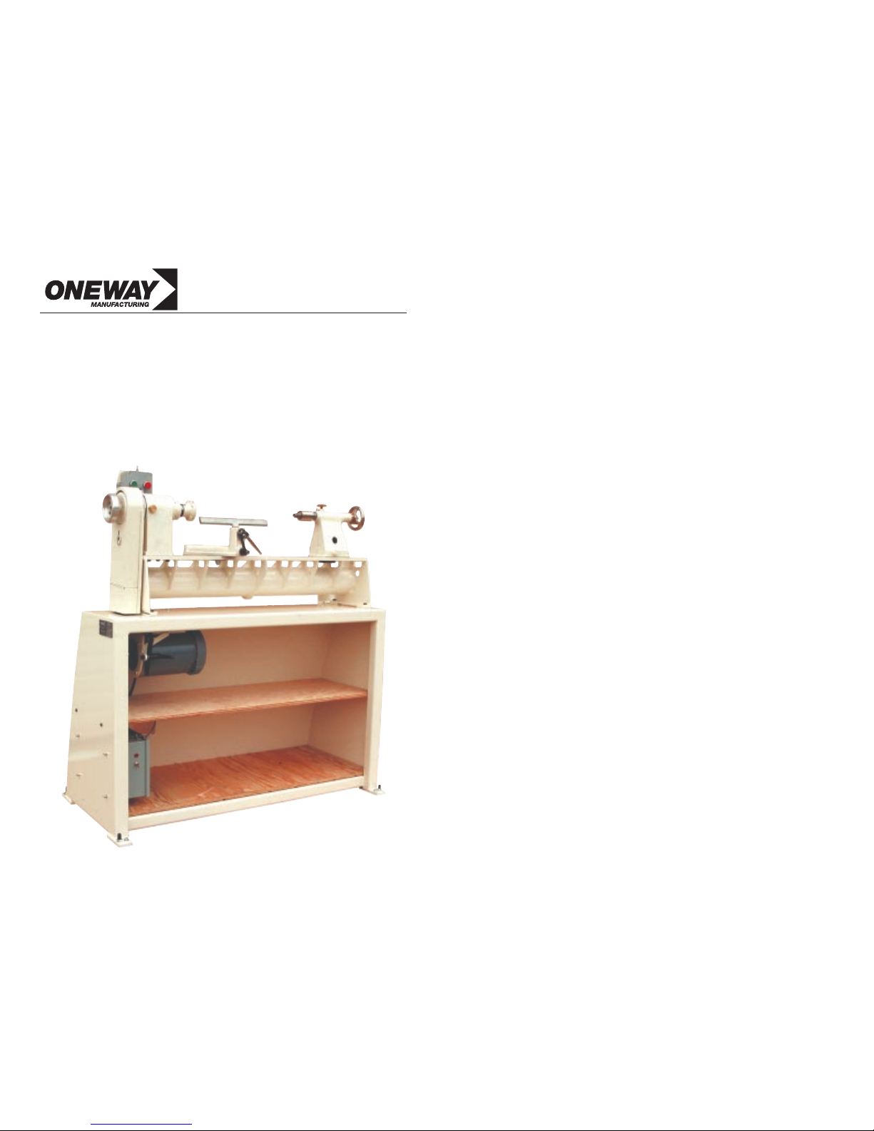
1224 Lathe
POWER AND PRECISION FOR TODAY’S WOODTURNER
Owner’s Manual
241 Monteith Ave, Stratford, ON, N5A 2P6, Canada
Phone: 1-519-271-7611
Fax: 1-519-271-8892
E-Mail: postbox@oneway.ca
1-800-565-7288
A Revolution in Lathes!
www.oneway.ca
Table of Contents
General Specifications
The Bed
The Headstock
The Spindle
The Banjo/Toolrest Base
Bearings
The Tailstock
Assembly and Set Up
The Drive
Control Description
Common Problems & How to Avoid Them
If The Drive Does Trip Out
Maintenance and Lubrication
Changing the Belt
Attaching & Removing Accessories From the Spindle
Indexing
General Safety
Accessories
Manufacturers Limited Warranty
Appendix
Wiring Diagram
M0185 - Banjo Assembly
M0181 - Tailstock Assembly
M0220 - Headstock Assembly
M0219 - Spindle Assembly
M0195 - Belt Cover Assembly
M0083 - Motor Mount Assembly
3
4
4
4
5
6
7
8-9
10
10
11
11
12
13
13
13
14-15
16
17
18
19
20
21
22
23
24
25
2

4
• Included: 3" faceplate, #2 MT
Live Centre and #2 Safe Driver,
Stainless Steel Toolrest, Lathe
Knock out Rod, Open Ended
Wrench, 4 levelling pads, 6 & 8
MM hex keys.
• Lathe runs extremely quietly
• Standard spindle height from
bottom of bench - 44-1/2"
• All painted surfaces are powder
coated
• Bench Dimension details:
Material: 10 Gauge steel
Top Surface: 46” * 12.2”
Footprint: 47” * 23-1/2”
Height: 30.15”
Top Shelf: 30” * 12”
Bottom Shelf: 36” * 14-1/2”
Options when purchasing this
machine include:
• 1 HP 220 volt standard
• 1 HP 110 volt
Lathe Specifications
Distance between centres - 24”
Overall length of lathe - 39.2”
Swing over bed - 12-1/2”
Swing over banjo - 9.0”
Stainless Steel Toolrest - 9” Blade, 1” Diameter Post
Weight with motor & bench - 300 lbs.
Spindle Taper - #2 Morse Taper
Tailstock Taper - #2 Morse Taper
Spindle Thread - 1” - 8 Threads per inch Right Hand
Backthread for vacuum attachments - 3/4 - 16 TPI RH
Congratulations on your purchase of a ONEWAY 1224 Lathe.
This manual describes general use and features of the ONEWAY 1224
Lathe. It is not meant to be a woodturning instruction book. If you are
new to turning, we recommend seeking out a qualified instructor in your
area. There are many national and local woodturning organizations that
can recommend instructors. If you are unable to take lessons, there are
many excellent books and videos available. Proper instruction will ensure
that you work safely and that you can use your new lathe at it’s optimum.
ONEWAY 1224 LATHE MANUAL
Other Specifications
3
Bedways and ribs are welded to a 4-1/2 inch diameter * 1/4 inch wall
tube. The assembly is stress relieved and precision machined.
Bedways are offset so chips and debris fall straight thru without sacrificing rigidity.
Almost perfect torsional rigidity is achieved - many times more than
twin tube or cast iron bed designs.
• Features a four bearing spindle: At the front are two deep groove
ball bearings custom fitted with ground spacers, and locked to the
shaft with a lock nut in the housing. This minimizes radial and
axial play of the spindle. The rear bearings float axially to allow for
heat expansion. Bearings are no maintenance greased for life.
• The spindle is 1-5/8" at maximum diameter and drilled thru 3/8"
with number 2 morse taper at the inboard end. It is made from
high strength alloy steel, hardened and ground to precision tolerance of ±0.0003 inches.
• A special self supporting wrench is used to remove accessories from
the spindle such as faceplates and chucks.
• 24 position indexing is standard.
The Bed
The Headstock
The spindle is 1" - 8 TPI with a groove machined for a lock screw. This
design contributes to the safety of this machine, as it reduces the possibility of chucks or faceplates accidentally unscrewing from the spindle,
especially when the machine is used in reverse. It is also safer when sanding and braking.
The Spindle
PAINTED BOWL
by David Loewy
5
6
The BANJO/TOOLREST BASE is ONEWAY's own proven design that
assures even, powerful locking anywhere on the bed (patented feature).
The sliding cam is supported by a cam support block which rests on a
ledge machined in the toolrest base. To ensure continuing smooth operation, lubricate the mechanism whenever it seems to be getting sticky.
The banjo handle will clamp either to the left or right. Generally the
handle is adjusted so that when it is clamped, the handle is clear of the
bed. This allows the banjo to be clamped in all positions over the bed.
The clamp handle position can be adjusted via the Nylock Nut, underneath the banjo.
How do I adjust the Toolrest clamp lever?
The toolrest clamp lever can be adjusted to clamp in any position. To
change the position of this lever, unscrew the four screws that hold the
clamp nut in place, rotate it to the desired position and re-fasten the nut
with the screws. Note that there are eight holes in the clamp nut, allowing adjustments of 1/8 rotational increments. The handle clamp position
is an individual preference, but the 4 O’clock position is a good place to
start.
Banjo - Toolrest Base
What is a sliding Cam assembly?
This assembly consists of: a rotating square shaft, a short sliding cam and a
support block for the sliding cam. The square shaft rotates the sliding cam.
The cam is supported on a cam support block
which in turn is supported on a
ledge machined in the tool rest
base. The block moves with the
sliding cam and supports the
shaft. Deflection of the cam shaft
is eliminated and there is no
longer a clamping difference
anywhere on the lathe bed.
Unclamp is always at the 12
o’clock position and clamping
may be adjusted to be repeatable
anywhere between 10 & 6
o’clock with RH and LH clamping always at the same angle.
Cam
Support
Block
Rotating Square
Shaft
Sliding
Cam
Support Ledge
There are four spindle bearings in the headstock. These bearings are sealed
and lubricated from the factory and should never need adjustment or lubrication. The bearings and the spindle in your lathe are designed to take normal woodturning forces for a long time. The best way to ensure long bearing
life is to never hammer against the spindle.
Due to the size and the preload on the bearings the lathe may run quite warm
when it is new. As the bearings break in they will run cooler but will still get
warm. Each lathe is run in at the factory and checked for excess temperatures,
but it is a good idea to keep the speed below 2000 rpms for the first 30 hours
of operation. This allows excess grease in the bearings to escape and for the
seals to break in. When replacing the bearings it is best to replace the front
bearings with a matched set from ONEWAY Mfg. The rear bearings can be
replaced by any equivalent bearing.
Replacing the Bearings
To replace the bearings you must remove the spindle. The first step is to take
the belt off the motor pulley. Remove the nut on the back side of the spindle and slide off the pulley. Remove the six bolts in the spindle nose cap. Grab
the nose cap and the entire
spindle assembly should
slide out. If it is tight, take
two of the bolts you just
removed and put them into
the two tapped holes in the
nose cap. Tighten them alternately and this will jack out
the spindle. If you do not have
a proper set of bearing tools, it
is a good idea to send the spindle back to ONEWAY to prevent damage to the spindle
and to the new bearings.
Bearings
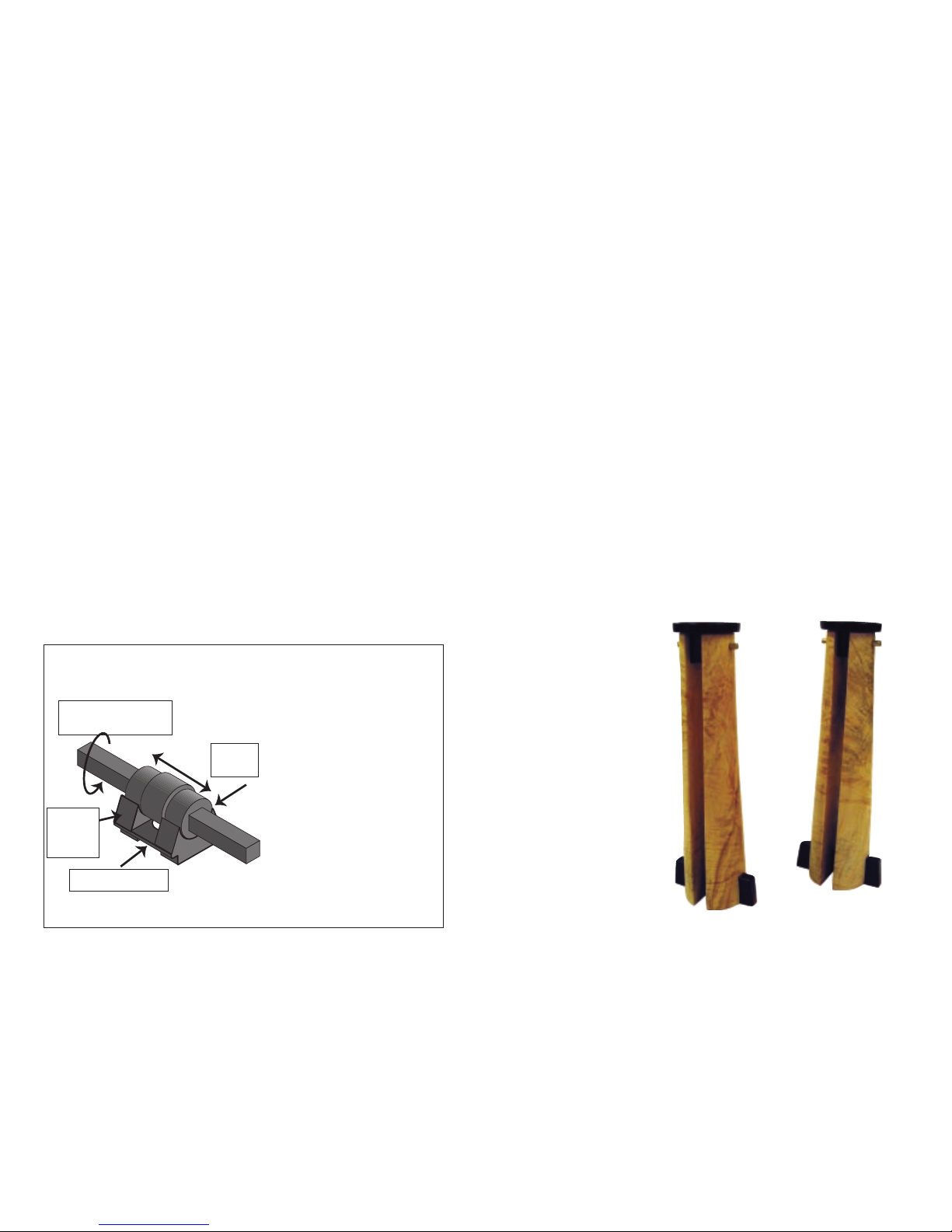
Candle Holders
by Christian Burchard

7 8
The tailstock on the ONEWAY 1224 is precision machined with a number
two morse taper which allows the use of stronger live centres and larger drills.
The lead screw is a 3/4" diameter 6 pitch acme thread and the barrel has a 3"
bearing length. A 4” handwheel and the high lead on this screw allows rapid
in and out feeds for drilling.
The quill is 1-1/8" diameter with 3" travel. The quill lock is the knurled brass
knob located on the top of the tailstock. It should be snugged up when using
a live centre. The lock does not have to be tightened excessively. This lock
does not stop the quill from backing off, that is done by the feed screw mechanism. The lock removes any play between the quill and the bore, to help
reduce vibration when working between centres.
The super rigid tailstock clamp is designed so that no flexing will occur under
clamp pressure. This will ensure that the clamp will hold firmly while requiring no adjustment for the life of the lathe, and will retain the ease of movement of the tailstock along the bed.
The Morse Taper in the tailstock is greatly affected by how clean the taper is.
Even a small amount of dust, or oil, will significantly reduce the drive force
that can be exerted by the tailstock before accessories will spin in the taper.
Always wipe any accessory and the taper with a clean rag before putting the
accessory into the tailstock.
Installation and Removal of
Accessories in the Headstock:
To install an accessory into the tailstock, wind the barrel out 1”. Put the
accessory in the barrel, and snap it into the taper. Most accessories are selfejecting. To remove the accessory, wind the barrel back until the accessory
pops out.
The Tailstock
The hardware required for setting up the ONEWAY 1224 Lathe is generally
attached at it's final destination. Most steps involve removing hardware, attaching a part, then using the same hardware to fasten the part.
Step 1: Remove the lathe from the shipping shelf. Use an 11 mm wrench to
loosen the two nuts attaching the lathe to the shipping shelf. If the carriage
bolts don't fall through, tap them through. These bolts are not required later.
Cut the cable ties attaching the electrical box to the lathe bed and remove the
lathe from inside the bench.
Step 2: Attach the Pendant Brackets.
Inside the bench there are two pendant brackets. Attach these to the top of the
bench with the hardware supplied. The centre rib must face the front.
Step 3: Position the pendant.
Your pendant will come in one of two ways:
a) The grey control box is physically attached to the pendant arm. If the control box is attached to the pendant arm, then the assembly can be pushed
through the hole in the back of the bench as a single unit. After the pendant is
through the hole, follow it with the black cover plate. Use the hardware supplied to attach the black cover plate to the bench.
b) The grey control box is not attached to the pendant arm. If the control
box is not attached to the pendant arm, then the grey control box needs to be
pushed through the hole on its own, followed by the pendant arm, followed by
the black cover plate. Attach the cover plate to the bench using the hardware
supplied. Once the control box and pendant arm are through the hole, attach
the control box to the pendant arm using the hardware supplied.
Mount the pendant onto one of the brackets attached to the bench in step 2.
Step 4: Attach the Shelf
Remove the shelf that the lathe was attached to. Flip the shelf over, making
sure the groove in the shelf is at the back left hand corner. Push the motor wire
into this groove. Lift the shelf so the left hand side is positioned onto the
bracket already attached to the bench. Lift the right hand side of the shelf so it
is higher than the holes drilled in the bench for the shelf bracket. Attach the
shelf bracket to the right hand side of the bench and lower the shelf onto the
support.
Step 5: Attach the Electrical Box
Remove one nut from each of four bolts on the left hand side of the bench.
Hang the electrical box on these bolts and attach it using the four nuts that
were just removed.
Assembly & Setup
 Loading...