

Page 1
M
M
o
o
d
d
e
ell
H
H
7
7
0
0
0
0
B
B
U
Usseerr''ss
M
Maannuuaall
FEB-9455 Main Board, 15 inch LCD’s
Page 2

Federal Communications Commission (FCC)
This equipment has been tested and found to comply with the limits for a Class A digital device,
pursuant to Part 15 of the FCC Rules. These limits are designed to provide reasonable
protection against harmful interference in a residential installation. This equipment generates,
uses, and can radiate radio frequency energy and, if not installed and used in accordance with
the instructions, may cause harmful interference to radio communications. However, there is no
guarantee that interference will not occur in a particular installation. If this equipment does
cause harmful interference to radio or television reception, which can be determined by turning
the equipment off and on, the user is encouraged to try to correct the interference by one or
more of the following measures:
Reorient or relocate the receiving antenna.
Increase the separation between the equipment and the receiver.
Connect the equipment to an outlet on a circuit different from that to which the receiver is
connected.
Consult the dealer or an experienced radio/TV technician for help.
Shielded interconnect cables and shielded AC power cables must be employed with this
equipment to insure compliance with the pertinent RF emission limits governing this device.
Changes or modifications not expressly approved by the system‟s manufacturer could void the
user‟s authority to operate the equipment.
Declaration of Conformity
This device complies with part 15 of the FCC Rules. Operation is subject to the following two
conditions:
1. This device may not cause harmful interference
2. this device must accept any interference received, including interference that may cause
undesired operation.
DHHS- the DVD-ROM Drive
FDA Regulations require the following statement for all laser-based devices:
“Caution, Use of controls or adjustments or performance of procedures other than those
specified herein may result in hazardous radiation exposure.”
Caution: This appliance contains a laser system and is classified as a “CLASS 1 LASER PRODUCT”.
To use this model properly, read the instruction manual carefully and keep this manual for future
reference. In case of any trouble with this model, please contact your nearest “Authorized Service
Station”. To prevent direct exposure to the laser beam, do not try to open this enclosure.
Page 3

Important Safety Information
SAFETY INSTRUCTIONS
1. Please read these safety instructions carefully.
2. Keep this User‟s Manual for later reference.
3. Disconnect this equipment from the AC outlet before cleaning. Don‟t use liquid or spray
detergent for cleaning. Use only a moistened sheet or cloth.
4. For pluggable equipment, the socket-outlet should be installed near the equipment and
should be easily accessible.
5. Keep this equipment from humidity.
6. Lay this equipment on a stable surface when installing.
7. Do not leave this equipment in an non-air-conditioned environment, or in a storage
temperature above 60∘C. Such conditions may damage the equipment.
8. The openings on the enclosure are for air convection and protect the equipment from
overheating. DO NOT COVER THE OPENINGS.
9. Check the voltage of the power source when connecting the equipment to the power outlet.
10. Place the power cord so that it will not be stepped on. Do not place anything over the
power cord. The power cord must be rated for the product and for the voltage and current
marked on the product‟s electrical ratings label. The voltage and current rating of the cord
should be greater than the voltage and current rating marked on the product.
11. All cautions and warnings on the equipment should be noted.
12. If the equipment is not used for a long time, disconnect the equipment from the mains to
avoid damage.
13. Never allow liquid into ventilation openings. This could cause fire or electrical shock.
14. Never open the equipment. For safety reasons, qualified service personnel should only
open the equipment.
15. If one of the following situations arises, get the equipment checked by service personnel:
a. The Power cord or plug is damaged.
b. Liquid has penetrated the equipment.
c. The equipment has been exposed to moisture.
d. The equipment does not work well or you cannot get it work according to the user‟s
manual.
e. The Equipment has been dropped and damaged.
f. The equipment has obvious signs of damage.
Caution: Danger of explosion if battery is incorrectly replaced. Replace only with same type, and discard used batteries
according to manufacturer‟s instructions.
Warnings: Not intended for Outdoor Use.
Page 4

Copyright
The information in this guide is subject to change without prior notice.
The manufacturer shall not be liable for technical or editorial errors or omissions contained
herein, nor for incidental or consequential damages resulting from the furnishing, performance,
or use of this material.
This manual contains information protected by copyright. No part of this manual may be
photocopied or reproduced in any form without prior written consent from the manufacturer.
© 2011 All rights reserved.
The software described in this guide is furnished under a license agreement or nondisclosure
agreement. The software may be used or copied only in accordance with the terms of the
agreement.
Product names mentioned herein may be trademarks and/or registered trademarks of their
respective companies.
First Edition March 2011
Page 5

T
Taa
b
bllee
o
off
C
C
o
o
n
nttee
n
ntt
CChhaapptteerr 11
1
1
Introduction 1
Model H700B Characteristics ............................................................................................... 1
How to Use This Manual ...................................................................................................... 2
A Visual Tour of Model H700B ................................ ................................ ............................. 3
What comes with Model H700B .................................................................................... 4
Dimensions15” .............................................................................................................. 6
Connector Panels ................................................................................................................ 7
CChhaapptteerr 22
8
8
Hardware Setup 8
Model H700B Assembly ....................................................................................................... 8
Hard Disk Drive Installation ................................ ................................ ........................... 9
Compact Flash Installation ................................................................ .......................... 10
Magnetic Card Reader Installation .............................................................................. 11
MCR Parameter Modification ...................................................................................... 13
VFD Customer Display Installation .............................................................................. 14
Cash Drawer Installation ............................................................................................. 15
Optional Second LCD Panel Display ........................................................................... 18
OSD Settings for Second LCD Panel .......................................................................... 19
CMOS Setup ..................................................................................................................... 20
CChhaapptteerr 33
221
1
Software Setup 21
Intel Chip Set Driver Installation for Windows XP ............................................................... 24
Graphic Media Accelerator Driver Installation .................................................................... 26
Lan Driver ................................................................................................................... 28
Audio Driver ................................................................................................................ 29
ELO Touch Tools Installation ............................................................................................. 29
ELO Touch Tools Installation for Windows XP & Vista ................................................ 29
ELO Control Panel ...................................................................................................... 35
Wireless LAN Driver Installation ......................................................................................... 37
CChhaapptteerr 44
440
0
Specifications 40
Jumper setting ................................................................................................................... 42
Connector function lists ...................................................................................................... 42
Connector pin define .......................................................................................................... 43
CChhaapptteerr 55
550
0
Troubleshooting 50
Power is on, but there is no Panel Display .................................................................. 50
Cannot Detect HDD .................................................................................................... 50
Touch Panel Does not Work ....................................................................................... 50
Page 6

ELO Touch Panel Cannot Calibrate Correctly ............................................................. 50
Second LCD Panel is Not Functioning Properly .......................................................... 51
PS/2 Keyboard is not functioning normally .................................................................. 51
MCR is not Functioning Properly................................................................................. 51
VFD Display is not functioning Properly ...................................................................... 52
LAN is not functioning Properly ................................................................................... 52
COM1, COM2 and COM3 are not functioning properly ............................................... 52
Cash Drawer Port is not functioning Properly .............................................................. 52
Page 7

9455 Main Board
1
CChhaapptteerr 11
IInnttrroodduuccttiioonn
Model H700B Characteristics
Model H700B uses a high speed processor capable of handling a high capacity of data
efficiently.
Model H700B‟s solid quality Aluminum housing distinguishes it from ordinary plastic
housings.
The Model H700B touch terminal all-in-one design combines a powerful PC, multiple
LCD and touch screens, which are suitable for any market. The primary LCD panel can
be tilted at multiple angles.
Model H700B‟s functionality extends far beyond the standard setup. Model H700B can
be adapted for a variety of uses with the addition of any of the following options:
Magnetic Card Reader, VFD/LCD customer display and cash drawer, Modem, LAN,
Audio devices, Compact Flash or USB devices (all available upon request).
Model H700B‟s security is designed to prevent data theft. The Model H700B system is
comprised of an internal 2.5” HDD making it hard to copy data without authority.
The solid aluminum design enhances heat dissipation and passes EMI testing.
Page 8

9455 Main Board
2
How to Use This Manual
This manual contains all the information you need to set up and use Model H700B. In addition,
you can also consult the manuals for the operating system and added hardware.
Chapter 1 Provides an introduction to Model H700B and this manual.
Chapter 2 Provides all necessary information for all hardware setup.
Chapter 3 Provides the necessary information for installing the Intel Chip set driver, Video
drivers and the touch screen tools, Audio, USB and LAN drivers.
Chapter 4 Lists all Model H700B specifications and Information for the I/O board
configuration.
Chapter 5 Provides information for troubleshooting Model H700B.
Page 9
9455 Main Board
3
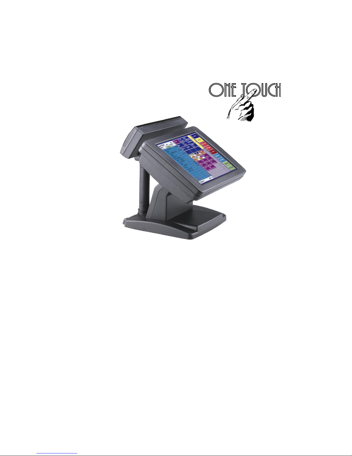
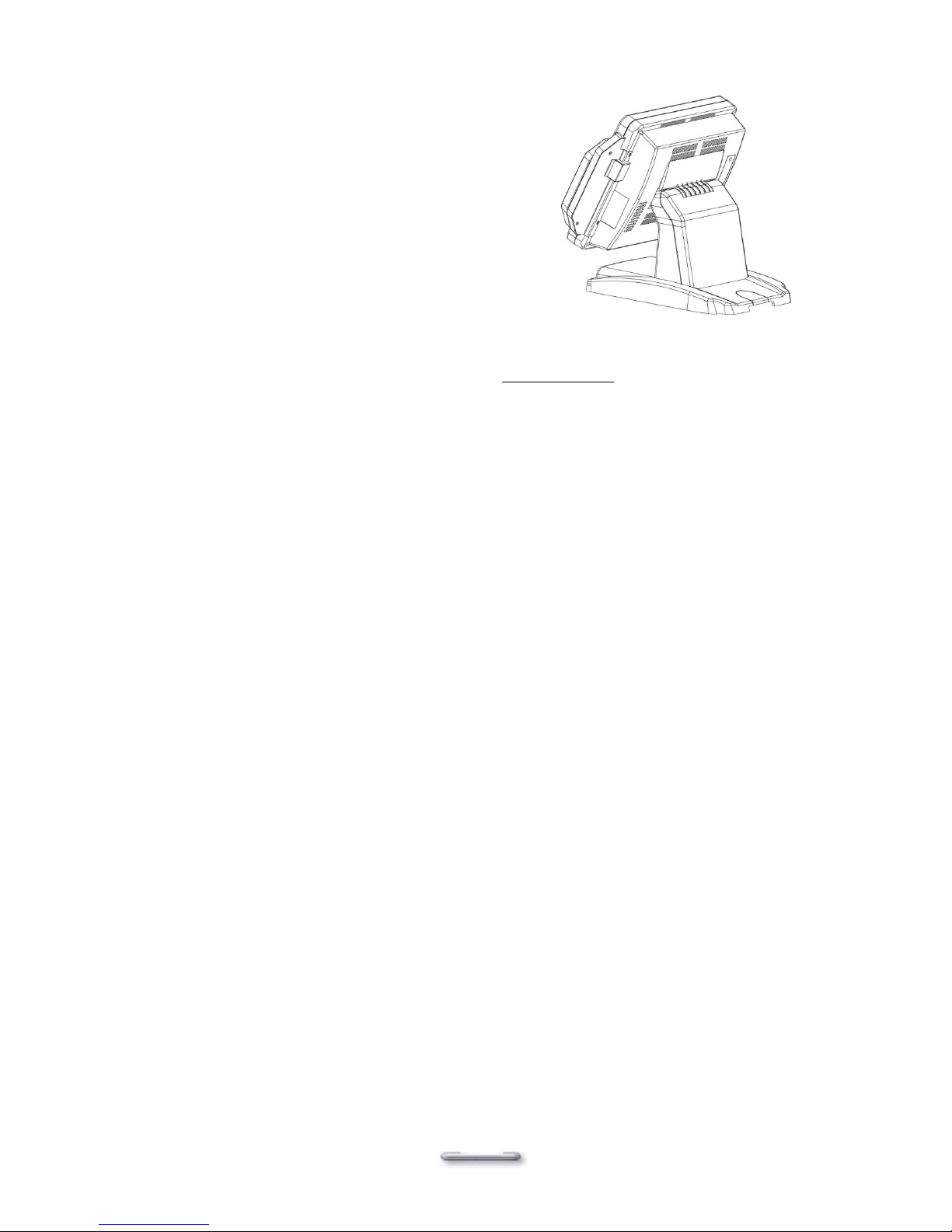
A Visual Tour of Model H700B
Before you start, take a few moments to become familiar with Model H700B.
USBX1
Page 10
9455 Main Board
4
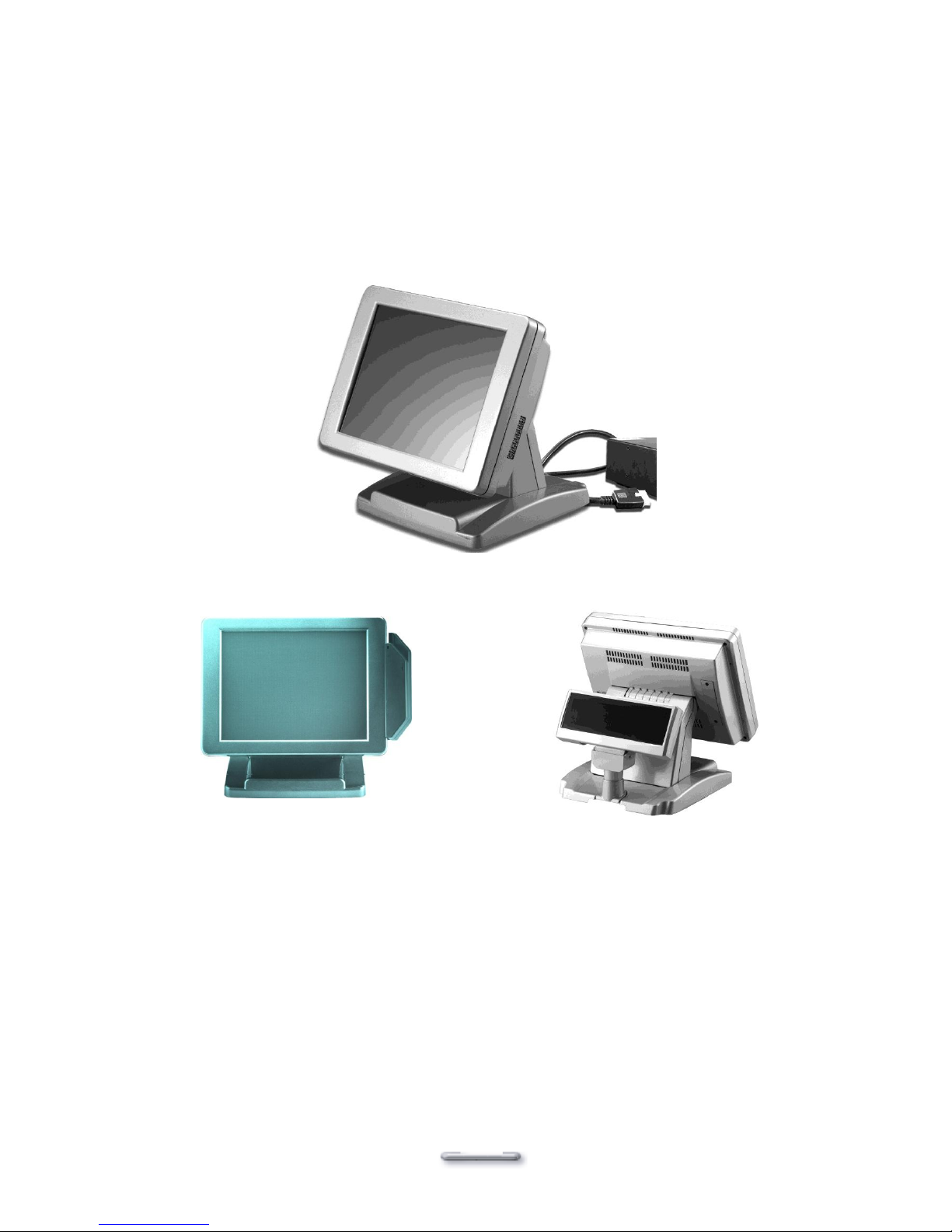
What comes with Model H700B
The following items are standard with Model H700B:
Main system with LCD panel
ATX power supply
One DVD contains driver, utilities and user‟s guide
AC power cord
Model H700B and power adapter
Model H700B with MCR
Model H700B with VFD
Page 11

9455 Main Board
5
The following items are optional:
Magnetic card reader (MCR) and bracket
VFD customer display
Page 12

9455 Main Board
6
Dimensions15”
Model H700B
Dimensions
Model H700B and
MCR Dimensions
Model H700B and
VFD customer
display
Page 13
7
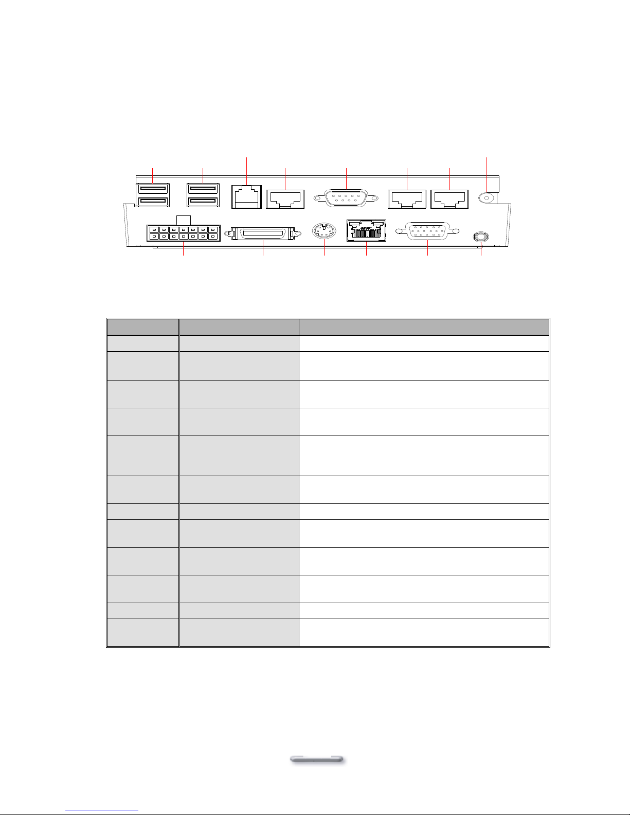
Connector Panels
The connector panel is located at the bottom of the main unit base. To clearly see the panel you
must turn Model H700B upside down.
Note: This configuration is for Model H700B units that have been supplied with an integral second LCD
panel.
I/O Port
Connector Type
Description
Power
DC Power Connector
Connects Model H700B to the power supply.
USB
USB
The USB (Universal Serial Bus) port can be used
to connect USB devices.
LAN
LAN RJ45 Connector
The LAN port is used to hook Model H700B to a
local area network.
K/B
PS/2 Keyboard
Connector
The K/B port for an external keyboard.
COM1
COM2
RJ45 Connector
The serial ports COM1/COM2 can be used to
connect serial devices such as a mouse or a
fax/modem.
VGA
15 PIN VGA Connector
The Ext VGA port is used to attach an external 2nd
Panel display or CRT monitor.
DC 12V Out
2 PIN Socket
This is used for the 2nd Panel display.
Cash
Drawer
RJ11 Connector
Cash Drawer Connector, 12 V Actuation support
for solenoid.
VFD/COM4
VFD/ COM4 RJ45
Connector
The VFD port is used to attach a RJ45 cable for a
VFD customer display.
COM3
DB9 Connector
The serial port COM3 can be used to connect
serial devices such as a mouse or a fax/modem.
Line Out
Earphone Connector
The audio port is for speakers.
LPT1
26 PIN SCSI II
Connector
The parallel port LPT1 can be used to connect
parallel devices, such as a printer.
USB USB
Cash
Drawer
COM1
DC+12 V
OUT
COM2COM3COM4
LAN
LPT 1
POWER
K/B
Speaker
VGA
Page 14
FEB-9455 Main Board
8
CChhaapptteerr 22
HHaarrddw
waarree SSeettuupp
Model H700B Assembly
Please make sure that the system power is turned off and the power supply is disconnected when
making any hardware changes to Model H700B.
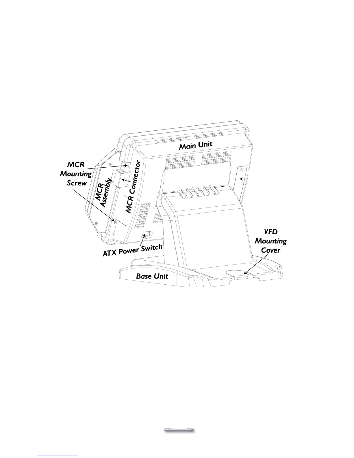
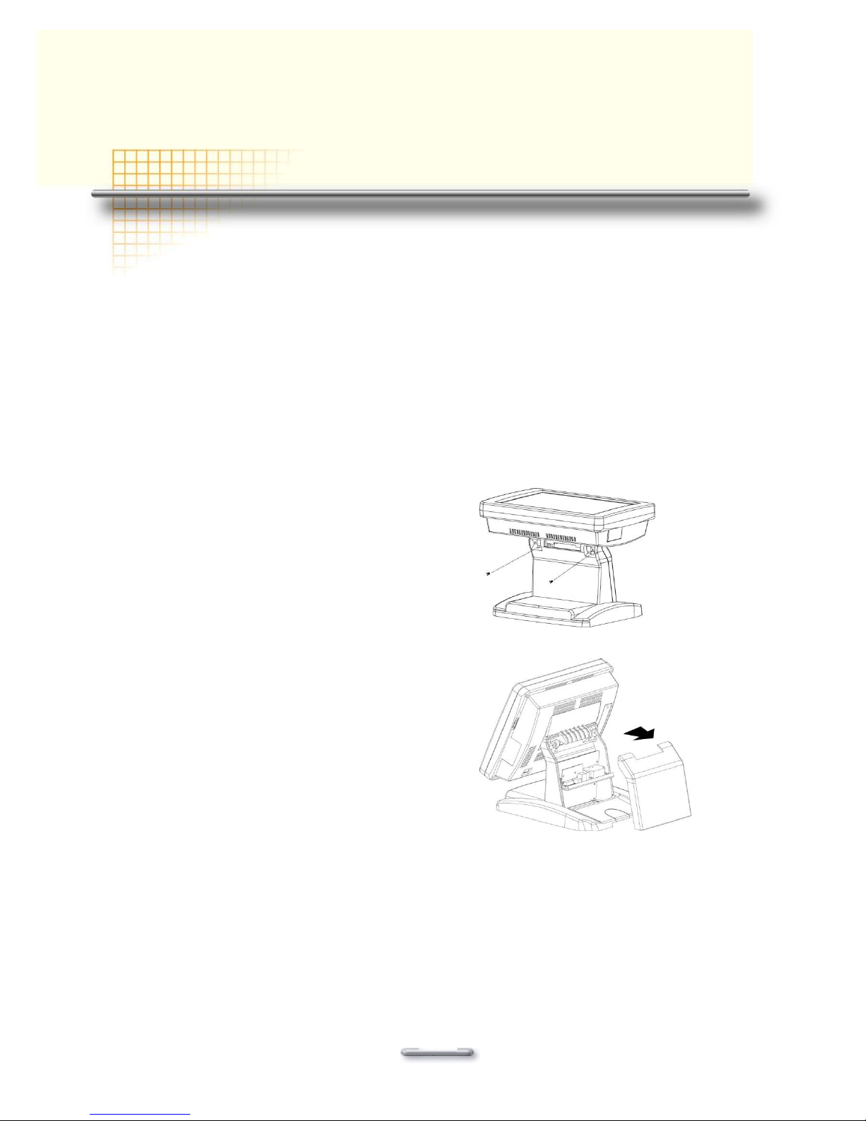
Remove the rear neck plate
I/O ports locate on the back of the neck. The rear neck plate must therefore be removed before
alterations can be made to the hardware.
1. Tilt the screen to 180 degrees.
2. Unscrew the 2 screws adjacent to the hinges.
3. Tilt the screen to 90 degrees.
4. Remove the rear neck plate.
5. Select the appropriate jumper settings as needed.
Page 15
FEB-9455 Main Board
9
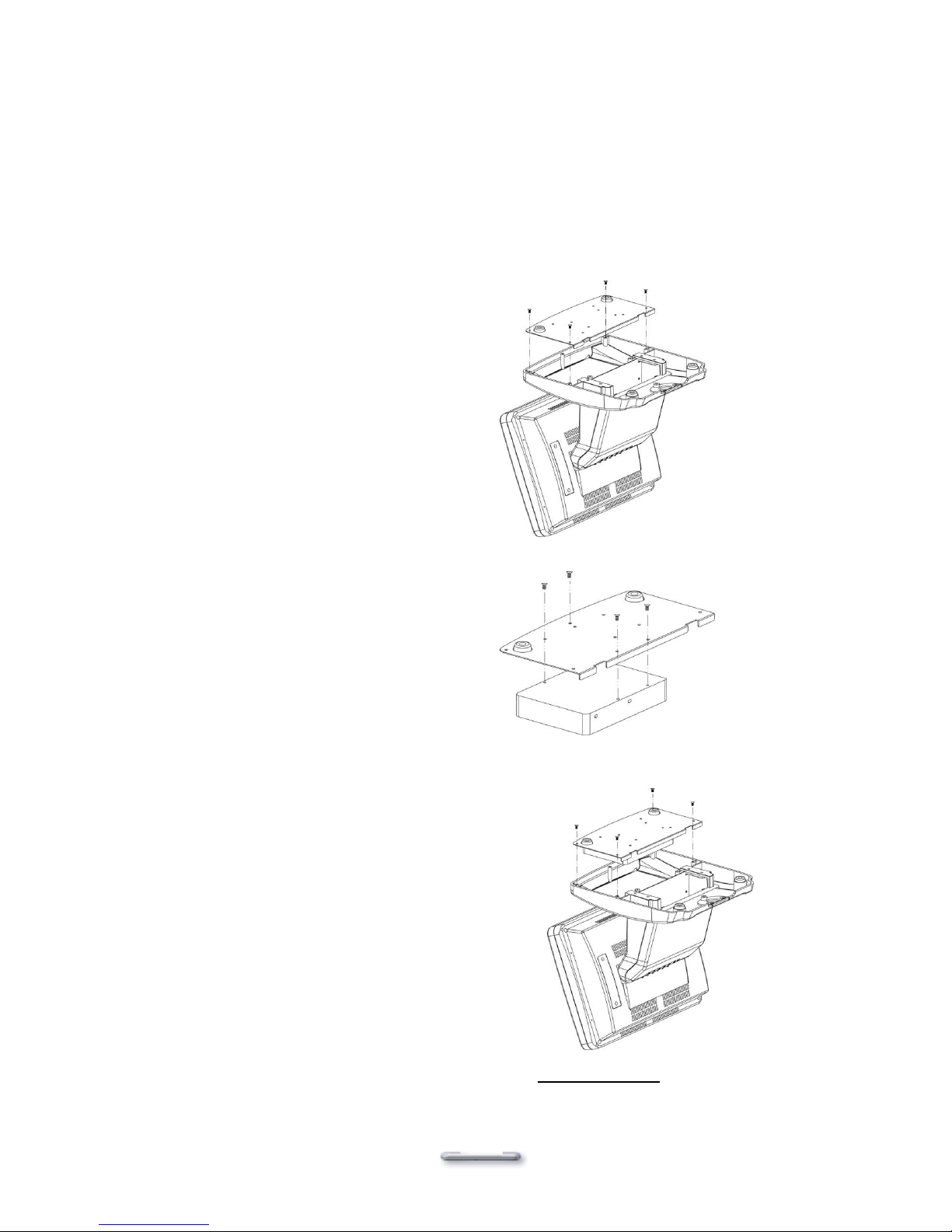
Hard Disk Drive Installation
Model H700B comes with an empty hard disk drive (HDD), unless a special request has been
made.
Installing a HDD
1. Turn off power and remove power cable from main unit.
2. Remove the Base/HDD Plate from the
base (4 screws).
3. Secure the hard disk drive on the plate (4
screws).
4. Plug the SATA cable to the HDD.
5. Put the plate back to the base and
secure with 4 screws.
6. Connect the main unit power.
Note: If the HDD does not work normally, please refer to troubleshooting.
Page 16
FEB-9455 Main Board
10
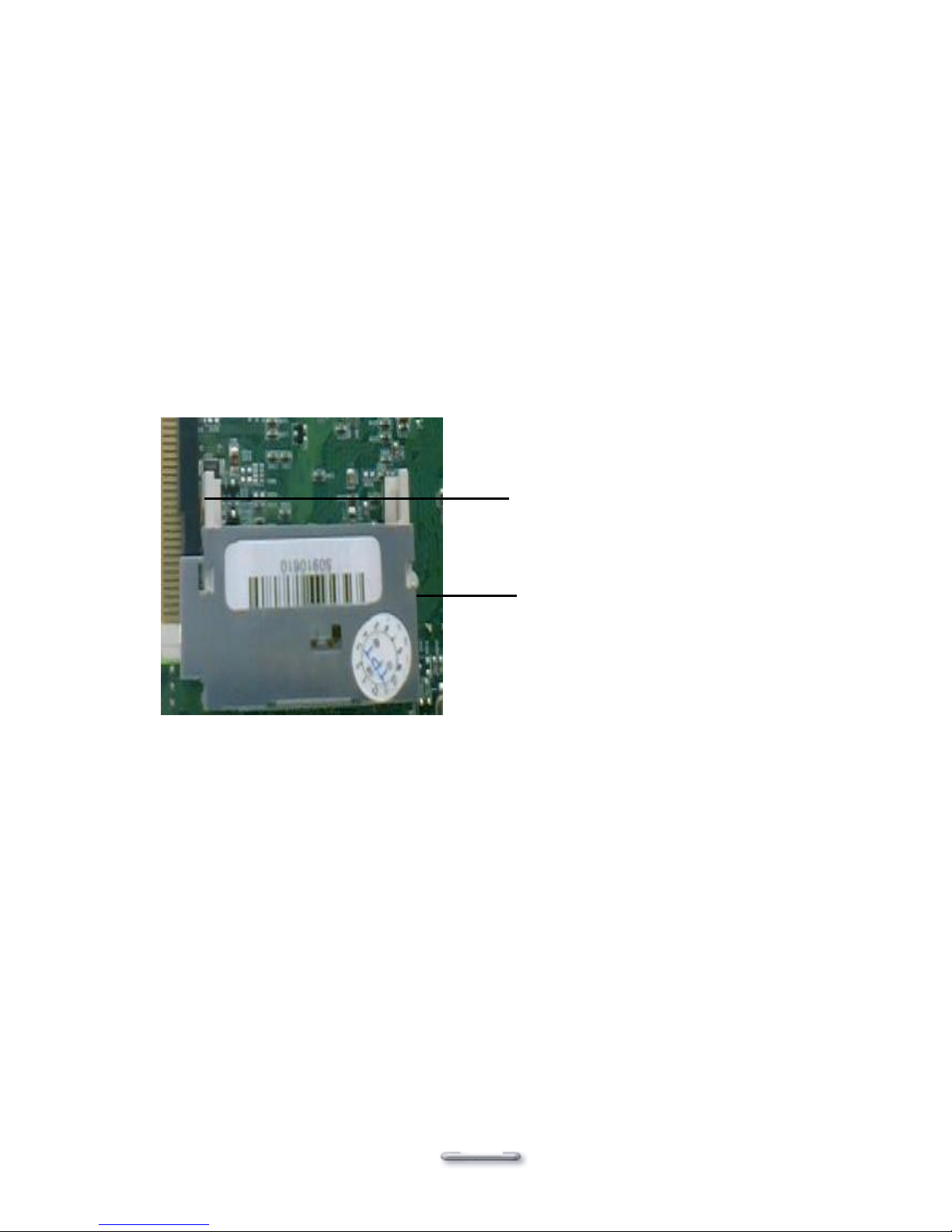
Compact Flash Installation
Model H700B will configure Compact Flash in IDE mode as secondary master after it is installed.
The next available drive letter will be automatically assigned to Compact Flash.
Installing Compact Flash
1. Turn off power and remove power cable from Model H700B.
2. As the compact Flash socket is located on the back side of M/B, remove the 4 screws and
disassemble the front panel plate.
3. Insert Compact Flash and lock the black lever in a 90 degree position.
4. Reassemble front panel plate to main unit.
5. Connect the main unit power.
Compact Flash
Black lever in a
90 degree
position
Page 17
FEB-9455 Main Board
11
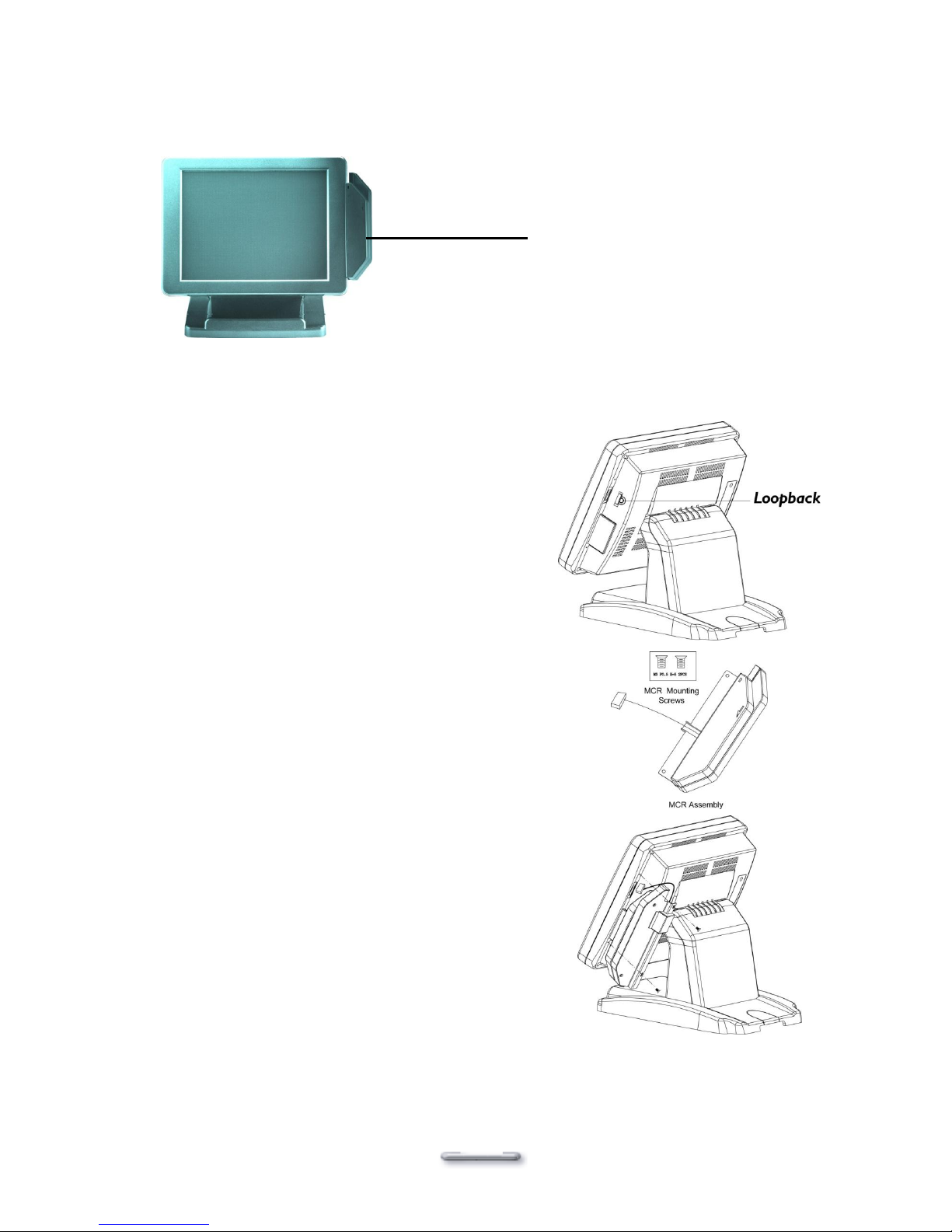
Magnetic Card Reader Installation
An optional Magnetic Card Reader (MCR) can be installed on the right side of Model H700B.
Installing an MCR
1. Turn off system power.
2. Unplug the loopback from the MCR socket. The
MCR socket is found on the right side on the
back of the main Unit.
3. Attach the MCR Assembly to the main unit and
connect the MCR cable to the MCR socket.
4. Secure the MCR to the main unit with 2 screws.
Magnetic Card Reader (MCR)
Page 18
FEB-9455 Main Board
12
5. Turn on system power.
Note: If the MCR does not work normally, please refer to troubleshooting.
Attention: The loopback or the MCR cable must be inserted in the socket for an external keyboard to
function with Model H700B.
Page 19

FEB-9455 Main Board
13
MCR Parameter Modification
This option is for users who need to customize the MCR parameters for a particular task.
Some of the useful parameters include:
The selection of country code, other than the default English.
The choice of track combinations.
The preamble/postamble codes.
The MCR parameters can be modified by using the supplied utility program.
The utility can be found on the DVD that came with your system in the \UTILITY\Pos Utility\MCR
util.
If you are upgrading and earlier system to include our MCR reader, then this utility can located on
our website at http://www.firich.com.tw/tech_drivers.htm in the section labeled as “MSR Utility”.
Unzip this file onto your system hard disk then run the “Setup.exe” in the MSR_Util folder and
follow the simple onscreen instructions.
When the installation finishes, you will find that a new folder has been created in your “Program
files” folder, labeled as “Decoder” with a subfolder named “XXX Decoder”.
When the program has loaded please select the Magnic_Reader menu item as in the following
picture. By using the 3 top items listed; Interface, Communication and Miscellaneous, you will
be able to alter many of the parameters associated with the MCR unit.
When you have finished your modifications and are sure that they are set exactly how you want
them to be, just click on the menu item Transmit to download the new parameter to the MCR unit.
Please refer to the Help menu for any further assistance.
Page 20

FEB-9455 Main Board
14
VFD Customer Display Installation
An optional VFD customer display can be installed on the back of Model H700B.
Rear view with VFD attached.
Installing a VFD
1. Turn off system power.
2. Important, make sure that the jumpers on the I/O board are set correctly. It's important to
note that the supply voltage for the VFD customer display(COM4 usually) is set to +12V. If an
LCD customer display is chosen, please change it to +5V.
3. Please refer to jumper information(p.40)
4. Remove the VFD Mounting Cover from
the base.
5. Secure the VFD Holder to the base
with 3 screws and place VFD display
into the holder.
Page 21

FEB-9455 Main Board
15
6. Connect the VFD RJ45 cable in the
VFD/COM4 port on the I/O panel
which located under the base.
7. Turn on VFD power switch, and then
turn on system power.
Note: If the VFD does not display correctly after an application is loaded, please refer to troubleshooting.
Cash Drawer Installation
A) Before the cash drawer has been connected to Model H800B, please make sure the
drive voltage and cable pin assignment of the cash drawer is matched to the definition of
the cash drawer port of Model H800B. Please refer to the mother board manual for
Check if the I/O ports are enabled in the CMOS setup.
B) Check if there are any IRQ conflicts.
C) The motherboard could be defective.
1. Cash Drawer .
2. Plug cash drawer cable into cash drawer port.
VFD
COM4
Page 22

FEB-9455 Main Board
16
Note: If the cash drawer cannot be detected by the system, please refer to troubleshooting.
Cash Drawer
RJ11
Connector
Page 23

FEB-9455 Main Board
17
Cash Drawer Activation
Two cash drawers may be driven from this port. Driving voltage of the solenoid is DC+12V.
Unlike previous models, the 9455 motherboard does not use a direct I/O port but instead is
accessed via a super I/O chip. A test program and source code is supplied and can be found on
the DVD in \Utility\Cashdrawer. This test program is for all Windows O/S. To use the source code
please study the readme.txt file in the same location.
Hardware logic is as follows.
Allow Access to the port
Boot DOS and use Debug.exe (you must boot raw DOS and not use WIN2K/NT/XP)
O 2E 87 ; This is the Super I/O access key (this is needs to be executed twice)
O 2E 87 ;
O 2E 07 ; This is the logical device access key
O 2F 07 ; This is the logical device number (07 = GPIO port #1)
O 2E F1 ; This allows access to the port registers bit7 - bit0 for reading and writing
To Open cash drawer number 1….
O 2F 01 ; This will power the cash drawer number 1 solenoid ON.
Wait 200 milliseconds
O 2F 00 ; This removes the power from the cash drawer solenoid.
To Open cash drawer number 2….
O 2F 02 ; This will power the cash drawer number 2 solenoid ON.
Wait 200 milliseconds
O 2F 00 ; This removes the power from the cash drawer solenoid.
There is only one input for the Cash Drawer Open Status Switch.
To read the Cash Drawer Open Status Switch for our Standard Cash Drawer
After Allowing Access to the port (above)
I 2F ; Read port 2F bit7 – bit0
Check the state of bit2, if High the drawer is open, if Low the drawer is closed.
If your application requires 2 cash drawers and you need to know if one of the drawers are open
then it will be necessary to link the “SW+” and “SW-“ of both cash drawers together. You will also
need to modify both cash drawer switch wiring.
You will need a soldering iron for this.
Disassemble the cash drawers and move the Red wire that is attached to the “N.O.” (Normally
Open) terminal onto the “N.C.” (Normally Closed) terminal. See the Cash Drawer RJ11 connector
details in this manual for pin assignments.
This will provide an “OR” type function.
e.g. either Cash Drawer 1 is open “OR” Cash Drawer 2 is open.
To read the Cash Drawer Open Status Switch…for 2 modified Cash Drawers
After Allowing Access to the port (above)
I 2F ; Read port 2F bit7 – bit0
Check the state of bit4, if Low a drawer is open, if High then both drawers are closed.
Page 24

FEB-9455 Main Board
18
Optional Second LCD Panel Display
An optional second LCD panel can be easily installed on Model H700B.
There are two standard pole heights that may be ordered, 150mm and 400mm.
The mechanical fitting of the second panel display is a very simple process.
Position the Model H700B onto its side.
Remove the 3 screws and Mounting Cover from the base unit.
Position the already assembled Second Panel Display, Pole and Holder to the base and
secure firmly with the 3 screws.
Now connect the Second Panel Display cables to the Power and VGA sockets on the
underside of the Model H700B unit. If you also ordered the second display Touch panel
option then connect this to the COM5 socket.
Note. CMOS BIOS settings should be altered to make COM5 use IRQ11, and boot
Display „CRT+LVDS‟ should be enabled.
Dependent upon which operating system is used, drivers will have to be installed,
therefore please refer to the DVD that came with your Model H700B, or visit our website
at: http://www.firich.com.tw/tech_drivers.htm
Page 25

FEB-9455 Main Board
19
OSD Settings for Second LCD Panel
Model H700B secondary LCD panel has built-in OSD (on screen display) controls to adjust
various display parameters. The control buttons are located on the right side of the back cover.
OSD Settings
There are four buttons on the OSD panel: Select, Down, Up, and Enter. The functions of these
four buttons are as follows:
Menu
Press to open the OSD window.
Back one menu level up.
Press to exit the OSD window while in OSD mode.
DownArrow
Press to scroll item selection bar down.
To decrease the parameter value.
To switch the item selection (Ex: YES / NO).
UpArrow
Press to scroll item selection bar up.
To increase the parameter value.
To switch the item selection (Ex: YES / No).
Enter
Enter the selected sub-menu.
Confirm selected function.
OSD Menu Structure
RGB Menu
Brightness
Red
-127~127
Green
-127~127
Blue
-127~127
Color Temp
0~7
Sharpness
0,1
Main Menu
Page 26

FEB-9455 Main Board
20
Geometry
Menu
AutoAdjustment
H. Position
0~252
V. Position
1~26
H. Total
1004~1108
Auto
Phase
Delay
0~61
Main Menu
Contrast
Menu
AutoBalance
Contrast
Red
0~511
Green
0~511
Blue
0~511
Balance
Red
0~127
Green
0~127
Blue
0~127
Main
Menu
0~127
Language
Menu
English
Spanish
Main Menu
Auto
Training
ON/OFF
DOS/GFX
ON/OFF
NVRAM
init
Power
Down
Revert
Save
CMOS Setup
Model H700B systems have adopted the motherboards 9455, using AWARD BIOS.
Please refer to the 9455 M/B User's Manual for a detailed description of the BIOS CMOS setup.
Page 27

FEB-9455 Main Board
21
CChhaapptteerr 33
SSooffttw
waarree SSeettuupp
Model H700B comes with a variety of drivers for different operating systems.
You will find 1 DVD with Model H700B. The DVD has all the necessary drivers to setup Model
H700B. Please insert the DVD into DVD-ROM. Installation will start automatically through
detecting your terminal‟s BIOS; there will be a menu for you to choose the driver you want.
Note: If you are installing WIN7, there‟s no need to install the chipset driver which is already
equipped as default with OS.
If the installation doesn‟t start automatically, please try to find the index.html file under the folder
D:\Driver List\ H700B_800B to start the driver menu as below.
1. Choose which OS you want or tools.
Page 28

FEB-9455 Main Board
22
2. Choose which driver you want to install, but please read the installation sequence carefully.
Page 29

FEB-9455 Main Board
23
3. Use the path and follow it to find the driver you want.
Please follow this installation sequence accordingly.
Model H700B Driver installation sequence:
Chipset Driver -> VGA Driver -> LAN Driver -> Audio Driver
The reason to follow our sequence is that IRQ settings will be changed by Windows XP to non
supported values, and you may encounter unnecessary problems later.
Note: When installing the IEGD driver for VGA under POSready 2009, the default
setting is 800x600 with Extention mode; please change the resolution setting to
1024x768 as below.
Page 30

FEB-9455 Main Board
24
Note: Under Windows 7, the chipset driver is not necessary since the OS has already
included the driver as default.
Intel Chip Set Driver Installation for Windows XP
Find the setup file through index
Step 1. Click “Next” to continue
Step 2. Read the License Agreement and click “Yes” to continue
Step 3. Click “Next” to continue
Page 31

FEB-9455 Main Board
25
Step 4. Click “Next” to continue
Step 5. Click “Finish” to complete setup
Page 32

FEB-9455 Main Board
26
Graphic Media Accelerator Driver Installation
Find the setup file through index
Step 1. Click “Next” to continue
Step 2. Read the License Agreement and click “Yes” to continue
Step 3. Click “Next” to continue
Page 33

FEB-9455 Main Board
27
Step 4. Click “Next” to continue
Step 5. Click “Finish” to complete setup
Page 34

FEB-9455 Main Board
28
Lan Driver
Find the setup file through index
Step 1. Click “Next” to continue
Step 2. Click “Install” to continue
Step 3. Click “Finish” to complete setup
Page 35

FEB-9455 Main Board
29
Audio Driver
Find the setup file through index
Step 1. Click “Next”
Step 2. Click “Finish” to complete setup
ELO Touch Tools Installation
ELO Touch Tools Installation for Windows XP & Vista
1. Find the setup file through index (Tools)
2. Open SW601379_TETouch_5.2.0
Page 36

FEB-9455 Main Board
30
3. Click OK to continue.
4. Click Unzip to continue the installation.
5. Click OK to continue.
Page 37

FEB-9455 Main Board
31
6. Pick the default language for the Elo Touchscreen and click Next to continue.
7. Check “Install serial Touchscreen Drivers” And click Next.
8. Read the “License Agreement” and click Yes if you accept it.
Page 38

FEB-9455 Main Board
32
9. Select “Auto-detect Elo touchscreens” and click Next.
10. Select the COM port for the touch monitor. It is recommended that you select COM5 for
the touch screen, as this port is internally configured for touch operation. And click Next to
continue.
11. Make sure the COM port listed is the one you chose for your touch monitor. Press Next to
continue.
Page 39

FEB-9455 Main Board
33
12. Wait until the ELO Touch Tools installation finished.
13. Select “Calibrate ELO Touchscreen monitors” and click Finish.
14. Start calibrating the touchscreen by touch the targets showed on the screen.
Page 40

FEB-9455 Main Board
34
15. If the cursor is working fine, click to finish the setting; if not, click to calibrate the
screen again.
IT MAY BE NECESSARY TO RESTART YOUR COMPUTER TO UTILIZE YOUR
TOUCHSCREEN FEATURES.
16. Click Restart to reboot your computer again.
Page 41

FEB-9455 Main Board
35
ELO Control Panel
This section explains the different options in the ELO control Panel.
General tab
The general tab allows you to:
Change the COM port your touch screen is set to.
Calibrate the touch screen with the Align button.
Mode tab
The Buttons tab allows you to:
Adjust all mouse emulation controls.
Change cursor properties
Enable or disable right mouse button utility.
Page 42

FEB-9455 Main Board
36
Sound tab
The Sound tab allows you to:
To change sound properties for ELO touch tools.
Properties tab
The Diagnostics tab allows you to:
View Controller Information.
Page 43

FEB-9455 Main Board
37
About tab
The About tab displays Information about ELO Touch systems
Wireless LAN Driver Installation
1. Find the setup file through index (Tools)
2. Open WiFi-118E.exe
3. Click “Next” and start the installation
4. Select “Install driver and Ralink WLAN Utility”
Page 44

FEB-9455 Main Board
38
5. Select “Ralink Configuration Tool”Select “Optimize for WiFi mode”
6. Select “Install”
Page 45

FEB-9455 Main Board
39
7. Click “Finish”
Page 46

FEB-9455 Main Board
40
CChhaapptteerr 44
SSppeecciiffiiccaattiioonnss
System Configuration
CPU (LGA775)
Intel Pentium Dual core E5300 2.6GHz
Chipset
Intel 945G + ICH7
DRAM
DDR2 400/533/667 MHz SDRAM. Up to 2GB 1 x 240 DDR2 DIMM
Primary LCD Panel
15” , LED/CCFL LCD Panel , 1024x768.
Primary Touch
Panel
15” ELO 5-wire resistive touch panel
CompactFlash
Disk socket
Type I/II CompactFlash™ Disk. The Flash Disk provides 100%
compatibility with hard disk.
HDD
Internal 2.5” 160GB hard disk drive (or above).
Hardware monitor
Built in to monitor power supply voltage and fan speed status
Speaker
2 watt pedestal-integrated speaker.
Power
250 watt external power adapter.
I/O Port
Serial Port
4 [1(DB9), 3(RJ45)]
Parallel Port
26 PIN SCSI II Connector
USB port
5
Keyboard Port
One PS/2 keyboard port.
LAN Port
10/100Mbps Ethernet Controller Realtek 8102E(Realtek RTL8111C
Optional)
VGA Port
Standard VGA Port for second LCD monitor.
Audio Port
Integrated Sound Blaster compatible, AC97 Audio Codec.
Construction
Optional Features
Injection-Molded, Die-cast aluminum enclosure spill resistance.
Customer display
Integrated VFD/LCD customer display.
Magnetic card
reader
Integrated Single/Dual/Triple Track MCR.
Second LCD Panel
15”/12”TFT LCD Panel.
Page 47

FEB-9455 Main Board
41
Second Touch
Panel
Optional 12”/15” ELO 5-wire resistive touch panel.
Operating
temperature
0°C~ 40°C (32°F ~ 104°F)
Page 48

FEB-9455 Main Board
42
Jumper setting
To Change the settings of COM, please adjust the jumpers on 2640 I/O board
COM1
5V : JP1_2 ( 5-6 short )
12V : JP1_2 ( 1-2 short )
RI : JP1_2 ( 3-4 short ) (Default)
COM2
5V : JP1_2 ( 11-12 short )
12V : JP1_2 ( 7-8 short )
RI : JP1_2 ( 9-10 short ) (Default)
COM3
5V : JP3_4 ( 5-6 short )
12V : JP3_4 ( 1-2 short )
RI : JP3_4 ( 3-4 short ) (Default)
COM4
RS-232:
JP3 ( 1-3 )
JP3 ( 2-4 )
5V : JP3_4 ( 11-12 short )
12V : JP3_4 ( 7-8 short )
RI : JP3_4 ( 9-10 short )
VFD:
JP4 ( 1-2 )
JP3 ( 1-2 )
JP3 ( 3-5 )
JP3 ( 4-6 )
12V : JP3_4 ( 7-8 short ) (Default)
Connector function lists
CConnector
Function
AUDIO1
6W amplifier Line-out Connector
AUDIO2
Line-in, MIC-In Connector
AUXFAN1
System FAN 3-pin Connector
BT1
Power Button Connector
CF1
Compat Flash Connector
Page 49

FEB-9455 Main Board
43
CPUFAN1
CPUFAN 4-pin Connector
COM5,COM6
Serial port Connector with Box-header
DIMM1
DDR2 240 Pin Slot
DIO1
Digital I/O with Pin-header
IDE1
HDD IDE Connector (Supply +5V)
INV1
LCD inverter Connector
IR1
IrDA Connector
MIO1
Multi IO Connector
MCR1
MSR Connector with Box-header
LAN
LAN Connector with Pin-header
LPT1
Printer Connector with Pin-header
LVDS1
LVDS Connector
PCI
PCI Connecting Finger
PWR1
ATX Connector with extension cable
PWR2
ATX 4 Pin Connector
SATA1, SATA2
SATA Connector
SATA_PWR1
SATA Power Connector
USB1, USB2,
USB3, USB4
USB Connector with Pin-header
-2, 9-11, 10-12, 23-24 15-
Connector pin define
Audio1 Audio Amplifier Output with Box-header (2.0 mm)
PIN No.
Signal
1
Audio Amplifier Out Right
2
Ground
3
Ground
4
Audio Amplifier Out Left
Audio2 Audio signal Connector with Pin-header (2.0 mm)
PIN No.
Signal
1
MIC1-IN-L
2
LINE1-IN-L
3
MIC1-JD
4
LINE1-JD
5
Ground
6
Ground
7
MIC1-IN-R
8
LINE1-IN-R
AUXFAN1 System FAN 3 Pin Connector
PIN No.
Signal
Page 50

FEB-9455 Main Board
44
1
Ground
2
Fan Power (+12V)
3
Speed Sense
BT1 Power Button with Pin-Header (2.54mm)
PIN No.
Signal
1
PSIN#
2
Ground
CPUFAN1 4Pin FAN Connector
PIN No.
Description
1
Ground
2
Fan Power (+12V)
3
Speed Sense
4
Control
COM5, COM6 Serial Port with Box-header (2.0 mm)
PIN No.
Signal
PIN No.
Signal
1
DCD
2
DSR
3
RXD
4
RTS
5
TXD
6
CTS
7
DTR
8
RI/+5V/+12V
9
Ground
10
NC
DIO1 Digital I/O Connector with Pin-header (2.54mm)
PIN No.
Signal
PIN No.
Signal
1
DIO-OUT3
2
DIO-IN3
3
DIO-OUT2
4
DIO-IN2
5
DIO-OUT1
6
DIO-IN1
7
DIO-OUT0
8
DIO-IN0
9
Ground
10
+5V
IDE1 HDD IDE Connector with Box-header (2.0mm)
PIN No.
Signal
PIN No.
Signal
1
RESET#
2
Ground
3
Data7
4
Data8
5
Data6
6
Data9
7
Data5
8
Data10
9
Data4
10
Data11
11
Data3
12
Data12
Page 51

FEB-9455 Main Board
45
13
Data2
14
Data13
15
Data1
16
Data14
17
Data0
18
Data15
19
Ground
20
NC
21
DMA REQ
22
Ground
23
IOW#
24
Ground
25
IOR#
26
Ground
27
IOCHRDY
28
Pull-down
29
DMA ACK#
30
Ground
31
INT REQ
32
NC
33
SA1
34
P66DETECT
35
SA0
36
SA2
37
HDC CS1#
38
HDC CS3#
39
HDD Active#
40
Ground
41
+5V
42
+5V
43
Ground
44
NC
INV1 Inverter Connector with Box header (2.50 mm)
PIN No.
Signal
1
+12V
2
+12V
3
Ground
4
Ground
5
Inverter Enable
IR1 IR Connector with Pin-header (2.54 mm)
PIN No.
Signal
1
+5V
2
NC
3
IR-RX
4
Ground
5
IR-TX
LAN LAN Connector with Box-header (2.0 mm)
PIN No
Signal
PIN No
Signal
1
L_MD10+
2
L_MD10-
3
L_MD11+
4
L_MD11-
5
L_P4&P5C
6
L_P7&P8C
7
L_MD12+
8
L_MD12-
9
L_ME13+
10
L_MD13-
Page 52

FEB-9455 Main Board
46
11
LED1#
12
LED0#
CN5 2nd LCD/VGA connector
PIN No
Signal
PIN No
Signal
1
Strobe#
2
Data0
3
Data 1
4
Data 2
5
Data 3
6
Data 4
7
Data 5
8
Data 6
9
Data 7
10
Acknowledge#
11
Busy
12
Paper Empty
13
Printer Select
14
Auto Form Feed#
15
Error#
16
Initialization#
17
Printer Select IN#
18
Ground
19
Ground
20
Ground
21
Ground
22
Ground
23
Ground
24
Ground
25
Ground
26
Ground
LVDS1 LVDS Panel Signal with Wafer Connector (1.25 mm)
PIN No
Signal
PIN No
Signal
1
Ground
2
Ground
3
L_DC3
4
L_DC3-
5
L_CLK0
6
L_CLD0-
7
L_DC2
8
L_DC2-
9
L_DC1
10
L_DC1-
11
L_DC0
12
L_DC0-
13
Ground
14
Ground
15
L_DC7
16
L_DC7-
17
L_CLK1
18
L_CLK1-
19
L_DC6
20
L_DC6-
21
L_DC5
22
L_DC5-
23
L_DC4
24
L_DC4-
25
Ground
26
Ground
27
LVDS Power
28
LVDS Power
29
LVDS Power
30
LVDS Power
Note:LVDS Power = +5V or +3.3V (Default)
MIO1 Multi-IO Connector with Box-header (2.54 mm)
PIN No
Signal
PIN No
Signal
1
DCD#4
2
DSR#4
Page 53

FEB-9455 Main Board
47
3
RXD#4
4
RTS#4
5
TXD#4
6
CTS#4
7
DTR#4
8
RI#4
9
DCD#3
10
DSR#3
11
RXD#3
12
RTS#3
13
TXD#3
14
CTS#3
15
DTR#3
16
RI#3
17
DCD#2/DT-
18
DSR#2
19
RXD#2/DT-
20
RTS#2
21
TXD#2/422R+
22
CTS#2
23
DTR#2/422R-
24
RI#2
25
DCD#1
26
DSR#1
27
RXD#1
28
RTS#1
29
TXD#1
30
CTS#1
31
DTR#1
32
RI#1
33
F_KCLK
34
F_KDAT
35
L_MCLK
36
L_MDAT
37
DIO_OUT0#
38
DIO_IN0
39
L_TX-
40
L_TX+
41
L_P4&P5C
42
L_RX-
43
L_RX+
44
L_P7&P8C
45
LED0#
46
LED1#
47
5VHSYNC
48
5VVSYNC
49
5VDDCCLK
50
5VDDCDATA
51
Ground
52
VGA_RED
53
Ground
54
VGA_GREEN
55
Ground
56
VGA_BLUE
57
Ground
58
HDD_LED#
59
FA-OUT-L
60
FA-OUT-R
MCR1 External Keyboard Connector with Pin-header (2.5 mm)
PIN No.
Signal
1
Ground
2
KDAT_CON
3
KDAT_KBC
4
KCLK_CON
5
KCLK_KBC
6
+5V
PWR1 ATX 8-pin Connector (Expansion cable) with Pin-header
PIN No.
Signal
1
+5V
2
+5V
Page 54

FEB-9455 Main Board
48
3
5VSB
4
+12V
5
PS_ON-
6
Ground
7
Ground
8
Ground
PWR2 ATX 12V 4-pin Connector
PIN No.
Signal
PIN No.
Signal
1
Ground
2
Ground
3
+12V
4
+12V
SATA PWR1 SATA 6pin Power Connector with Box-header (2.5 mm)
PIN No.
Signal
1
+5V
2
+5V
3
Ground
4
Ground
5
+12V
6
+12V
USB1 USB0 Port Connector with Pin-header (2.0mm)
Pin No.
Signal
1
USB Power (+5V)
2
USB DATA0-
3
USB DATA0+
4
Ground
USB2 USB1 Port Connector with Pin-header (2.0mm)
PIN No.
Signal
1
USB Power (+5V)
2
USB DATA1-
3
USB DATA1+
4
Ground
USB3 USB2, USB3, USB4, USB5 Port Connector with Pin-header (2.0mm)
PIN No.
Signal
PIN No.
Signal
1
USB DATA2-
2
USB DATA4-
3
USB DATA2+
4
USB DATA4+
5
Ground
6
Ground
Page 55

FEB-9455 Main Board
49
7
USB DATA3-
8
USB DATA5-
9
USB DATA3+
10
USB DATA5+
USB4 USB6, USB7 Port Connector with Pin-header (2.0mm)
PIN No.
DESCRIPTION
1
USB DATA6-
2
USB DATA6+
3
Ground
4
USB DATA7-
Page 56

FEB-9455 Main Board
50
CChhaapptteerr 55
TTrroouubblleesshhoooottiinngg
Please note that the following troubleshooting guide is designed for people with strong
computer hardware knowledge such as System Administrators and Engineers.
Power is on, but there is no Panel Display
A) Enter BIOS setup program and then get into the Boot Display option. Check if the default
setting is [ Auto ]; if not, change the setting to [ Auto ] and press F10 to save the settings.
B) Due to the chipset limitation, while two displays are connected to the system, both display
contents will shrink and cannot show properly in size under DOS mode. After the system
booting completed and running under the Windows OS, the display will show in normal
size.
Cannot Detect HDD
A) SATA cable is not connected properly to mainboard SATA1/SATA2 or it could be
defective.
B) HDD power cable is not connected properly to the mainboard or it could be defective.
C) Check CMOS setup, set SATA HDD to Auto detects.
D) On-board IDE port could be defective.
Touch Panel Does not Work
A) Check CMOS settings, COM port needs to be “Enabled”. And check the IRQ from the
MB manual
C) Check if the ELO driver has been properly installed. Or try to reinstall again
(Please refer to the ELO driver installation).
D) Check that the ELO controller on COM port has been detected during the ELO driver
installation. If yes, than check that the flat cable from the ELO touch screen has been
properly connected to the ELO controller (Attention: Pin1 mark should be on the same
side as the ELO controller).
E) Check that the ELO controller Green LED is blinking?
If no, there is no DC+5V support for the ELO controller from the mainboard.
F) Touch screen controller could be defective or the touch panel could be defective.
ELO Touch Panel Cannot Calibrate Correctly
A) Please replace the ELO controller, and re-calibrate. If this works, change back to the
Page 57

FEB-9455 Main Board
51
original ELO controller, and re-calibrate.
B) If the ELO touch panel still cannot calibrate correctly after changing to a new ELO
controller, the touch panel may be not installed properly or it could be defective.
Second LCD Panel is Not Functioning Properly
A) Check that the VGA driver is installed properly (Please refer to the VGA driver installation
section).
B) Connect a VGA CRT monitor to the VGA 2(onboard wafer) connector, if there is a display,
then the second LCD panel could be defective or is not installed properly.
B-1) Please check that both the VGA signal cable and second LCD power cable are
connected properly (Shut the power off before connecting the 2 above mentioned
cables).
B-2) Check that the VGA cable is connected to A/D board. Or it could be defective.
B-3) Check that the LCD signal cable is properly connected to A/D board and LCD
panel. Or it could be defective.
Please re-connect both ends of the LCD signal cable in the correct location. Or
replace with a new cable.
B-4) there will be no backlight if the is inverter is defective.
C) Check the 10 PIN VGA cable is well connected to main board VGA2
D) The main board VGA chip could be defective.
PS/2 Keyboard is not functioning normally
A) Make sure the keyboard is properly connected to the PS/2 keyboard port before the
system is powered up. If the keyboard is connected after OS has been booted, the
keyboard will not work.
B) Check that the LED on the keyboard goes on then off after power on. If yes, the
keyboard is getting power correctly.
C) If the MCR is not required. Please make sure the loopback is plugged into the MCR
connector board.
D) Check that the 6 wire cable has been properly connected between the MCR connector
board and mainboard MCR1.
E) The mainboard could be defective.
MCR is not Functioning Properly
A) Check if the green MCR LED is on.
A-1) Check if the MCR is properly connected to the MCR connector board on main
system.
A-2) Make sure the 6 wire cable is properly connected between mainboard MCR1 and
the MCR connector board.
A-3) The MCR connector board could be defective.
A-4) The MCR module could be defective.
B) If a keyboard is connected to the PS/2 keyboard port, and functions correctly, then the
MCR module could be defective.
Page 58

FEB-9455 Main Board
52
C) For an MCR to work under Windows2000, the keyboard must be connected prior to
booting the system.
VFD Display is not functioning Properly
A) Ensure that COM4 is enabled in the CMOS setup, and data is written to COM4 in the
application.
B) Check if there is any display when system power is ON, if the screen is blank, please
follow the steps below.
B-1) Make sure the power switch on the VFD display is on before powering the main
system.
C) Check RJ-45 cable is properly connected to main board
D) The on-board COM4 I/O chips could be defective.
LAN is not functioning Properly
A) Check if the LAN driver is installed properly. (Please refer to the LAN driver installation)
B) Check if there are any IRQ conflicts.
C) Check if the RJ45 cable is properly connected.
D) The on board LAN chip could be defective.
COM1, COM2 and COM3 are not functioning properly
D) Check if the I/O ports are enabled in the CMOS setup.
E) Check if there are any IRQ conflicts.
F) The motherboard could be defective.
Cash Drawer Port is not functioning Properly
A) Make sure the pin assignment matches between the cash drawer and the RJ11 cash
drawer port.
B) Verify the digit I/O port address is 2F
C) The motherboard could be defective.
 Loading...