

One Tech 1C-B4XDD, 1C-B4MSD User Manual
User Manual For
Mobile Digital Video Recorder
Page 1 of 59
1C-B4XDD

NOTICE
The information in this manual was current when published. The manufacturer reserves the right to revise and
improve its products. All specifications are therefore subject to change without any notice.
The purpose of this manual is to kindly aid the user for the operation for our MDVR (especially for GUI setting). The
user should have a basic understanding of computer operation and basic knowledge of how to connect peripherals
and make some settings.
Page 2 of 59
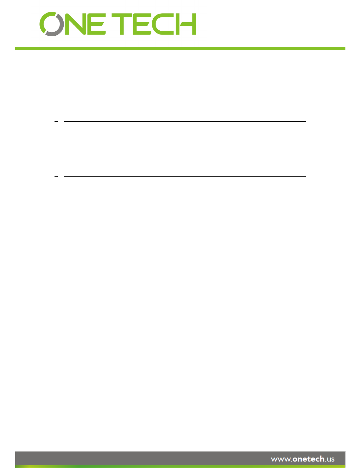
Table of Content
1 PRODUCTION CHRACTERISTICS AND OVERVIEW 5
1.1 PRODUCT OVERVIEW 5
1.2 REMOTE CONTROL 6
1.3 GUI (GRAPHIC USER INTERFACE) TREE 9
2 SYSTEM START UP 9
3 GUI CONFIGURATION 11
3.1 SEARCH 12
3.1.1 REC. SEARCH 12
3.1.2 EVENT FILES 15
3.2 SETUP 17
3.2.1 SYSTEM 18
3.2.1.1 DATE/TIME 18
3.2.1.2 OPTIONS 20
3.2.1.3 REGISTER INFO 22
3.2.1.4 FORMAT 22
3.2.1.5 UPGRADE 23
3.2.1.6 USER SECURITY 25
3.2.1.7 CONFIG 27
3.2.1.8 USER LOG 27
3.2.1.9 BLACKBOX FILE 28
3.2.1.10 GEO-FENCING 29
3.2.2 RECORD 30
3.2.2.1 OPTION 30
3.2.2.2 OSD OVERLAY 33
3.2.2.3 CAMERA SETTINGS 34
3.2.2.4 RECORD SETTING 35
3.2.2.5 SUB-STREAM 35
3.2.2.6 SCHEDULE 36
3.2.2.7 OTHER SETTINGS 37
Page 3 of 59

3.2.3 NETWORK 39
3.2.3.1 LOCAL 39
3.2.3.2 SERVER NETWORK 40
3.2.3.3 WIFI 41
3.2.3.4 MOBILE NETWORK 42
3.2.3.5 FTP SETTINGS 44
3.2.3.6 FTP FOR SNAP 46
3.2.4 EVENT 47
3.2.4.1 SENSOR 47
3.2.4.2 SENSOR OUTPUT 48
3.2.4.3 SPEED 50
3.2.4.4 ACCELERATION 50
3.2.4.5 TEMPERATURE 51
3.2.4.6 CAMERA 51
3.2.4.7 VOLTAGE 52
3.2.4.8 EMERGENCY EVENT 53
3.2.5 PERIPHERAL 54
3.2.5.1 PTZ 54
3.2.5.2 EXT.COM SETUP 55
3.2.5.3 SMART BATTERY 55
3.2.5.4 LANGUAGE SETTING 55
3.3 INFORMATION 56
3.3.1 SYSTEM 56
3.3.2 DIAL STATUS 57
3.3.3 HISTORY 57
3.3.4 MODULES 58
3.3.5 BATTERY INFO 59
Page 4 of 59

1 PRODUCTION CHRACTERISTICS AND OVERVIEW
1.1 PRODUCT OVERVIEW
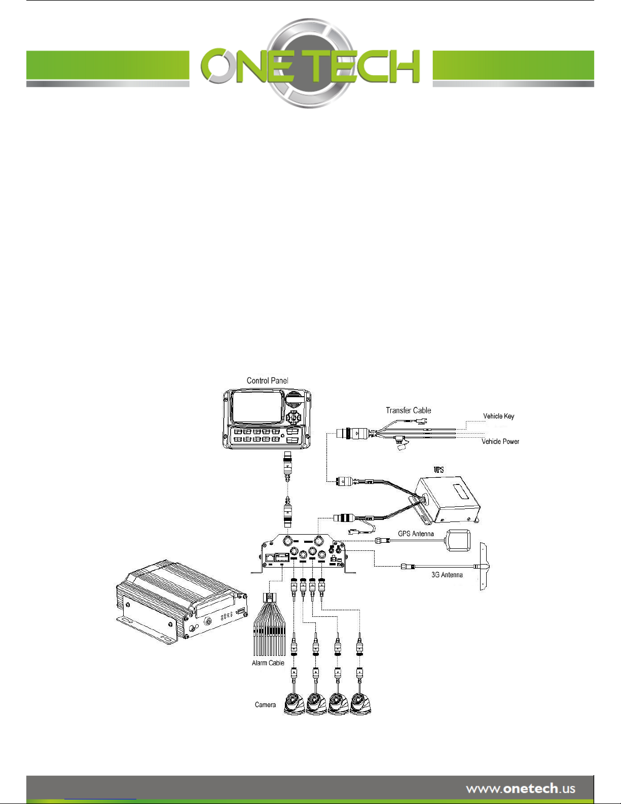
SVT-MDVR-X3A is middle range MDVR model specially designed for vehicle surveillance and remote monitoring,
combined with high-speed processor and embedded operating system. The advanced H.264 video compression
and decompression, wireless transmission, GPS location make X3A to be a very powerful and perfect solution for
vehicles.
MDVR Features and Capabilities
Support hard disk recording
UPS (Uninterrupted Power Supply) supported to protect the MDVR from the damage of high voltage and
provide the power to the MDVR when the MDVR external power is cut off (for example accidents happen)
Dual streams: one for local recording and one for wireless transmission.
4 channel real-time D1 at 25 fps/30fps continuous or priority video recording and live view display.
Semi-transparent GUI makes setting for GUI and live display synchronously.
Maximum 1 hour pre-recording and 30 minutes post-recording
Watermark prevents any modification in recorded file which is part of the law enforcement.
4 channels for high-fidelity, digitally recorded, synchronized audio matched to 4 video channels
User friendly criteria to playback the events associated video only.
Automatic timer to resume the live display if the unit is idle for user defined time.
User-selectable settings for quality and audio record enable/disable for each video channel.
12v power supply for multiple devices such as cameras, sensors, relays and any other accessories.
Remote Connection Capabilities
PC-Based Client software for live view, playback video, playback events associated video, and download
capabilities. Support CMS (Central Management System) for remote monitoring via built-in 3G module
(HSPA or EVDO), Ceiba (Playback Analysis Software) for video playback, meta-data analysis.ADS by WIFI
to download the video files and event files.
Page 5 of 59
OneTech patented special file system is professional to improve the security level of data, provide
self-recovery function, self-check, self-backup for certain critical data and avoid data fragment that affects
system efficiency.
1.2 REMOTE CONTROL
Each MDVR includes remote control that allows the user to transmit commands to recording module
Numeric
Input Keys
Use the numeric button to input
digital in setup
menu or switch the full screen for each
channel or the channels QUAD view
Navigation
Arrows
Use the ARROW keys to move between
selections, input fields and icons.
Press ENTER to select
And EXIT to return and entering into the OSD
screen to check the MDVR working status.
Next and previous is also used to increase or
decrease volume when at live or search
screens.
Page 6 of 59
and display on screen control menu
Remote Control Key Functions:
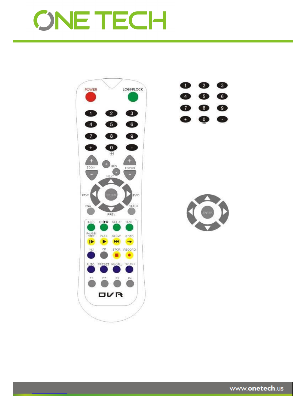
1) Numeric Keypad
[0-9] keys: During setup, number keys are used to input number values. In QUAD view, the user
can press 1, 2, 3 and 4 to switch the full screen for each channel, and press 0 to switch to quad view.
During full screen view of each camera, the user can press key to adjust contrast,
luminance, color and saturation, and then press + and - to make the adjustments. Pressing
will navigate through the color adjustment options.
2) Setup Menu Navigation
▲, ▼: Up, down directional keys: Move selection up and down in setup menu.
►, ◄: Left, Right directional keys: Move cursor left or right in setup menu.
[ENTER] key: During setup, select and save the settings
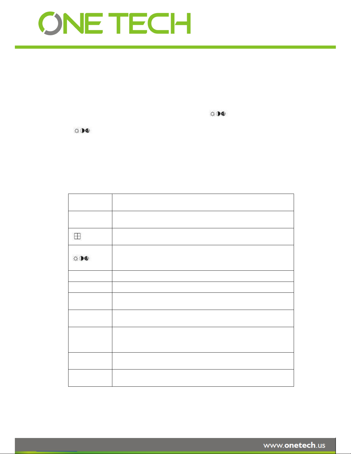
3) Other Keys Function
LOGIN/ LOCK
The user can press LOGIN / LOCK or SETUP key to enter the GUI to setup. If
password is enabled, the user have to input default admin password: 88888888.
POWER
To reset the MDVR to sleep mode (The user can press power button again to let
MDVR start up when it is in sleep mode).
Switch full screen of one channel to quad view.
Brightness, contrast, color adjustment for each channel. Use [+] [-] button to
change the values. The user have to adjust the values for each channel
individually.
SETUP
Login GUI to setup the parameters.
EXIT
Return to the previous menu.
STOP
Used to stop the recording manually. Only valid when the user setup the record
mode by the setting in MDVR menu
RECORD
Used to start the recording manually. Only valid when the user setup the record
mode by the setting in MDVR menu.
PAUSE/STEP
▐►
Freezes playback to a single frame and can advance one frame at a time. To
advance the frame press. Pause / Step to move frame by frame. Press EXIT to
return to normal playback speed.
PLAY
►
Starts/Resumes playback from any other mode (FF, RR, Frame by Frame etc).
SLOW
Reduces playback speed to 1/2, 1/4, 1/8 modes. Press PLAY to return to normal
playback speed.
Page 7 of 59
Please put the battery into the remote control before the user use it as there is no
battery in the standard package
GOTO
Quick search mode when the user playback the record file in MDVR. Press GOTO
button and input the desired time, and the select SURE to jump to the specific time
the user want to playback.
NEXT
Increase volume while playback (if audio is recorded).
PREV
Decrease volume while playback (if audio is recorded).
REW
Rewinds the video while playback. X2 and X 4 modes available.
FWD
Fast forward the video while playback. X2 and X4 mode available.
CF
No use at present.
[F1]
Export all the event record files of the day to USB by press F1 key.
[F2],[F3],[F4]
Reserved for future use.
4) PTZ Function Key
X3A DVR can support PTZ camera by the protocol PALCO-D or PALCO-P. While the MDVR is
connected the PTZ camera by RS485 signal (on the RS232/485 expand box), following commands can
control PTZ:
[ZOOM IN +], [ZOOM OUT -]
ZOOM IN/OUT
[IRIS +], [IRIS-]
Brightness control
[FOCUS +], [FOCUS -]
Focus control
PTZ
Enable the PTZ function
AUTO
Auto run with the PTZ pattern
PRESET
Preset default position
RECALL
Recall the position that the user have setup.
BRUSH
Brush the glass screen
Page 8 of 59
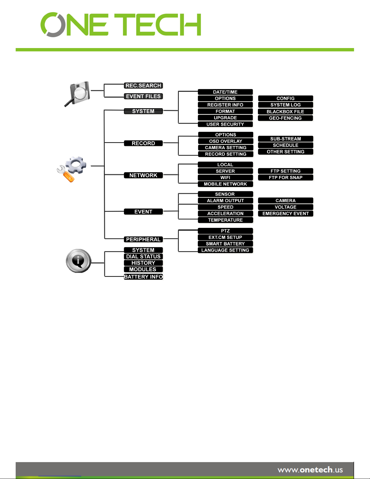
1.3 GUI (GRAPHIC USER INTERFACE) TREE
2 SYSTEM START UP
After connecting the MDVR to a vehicle power supply, turn on the vehicle ignition and the unit will
automatically start up. Power is normally supplied to the MDVR as long as the vehicle ignition is ON.
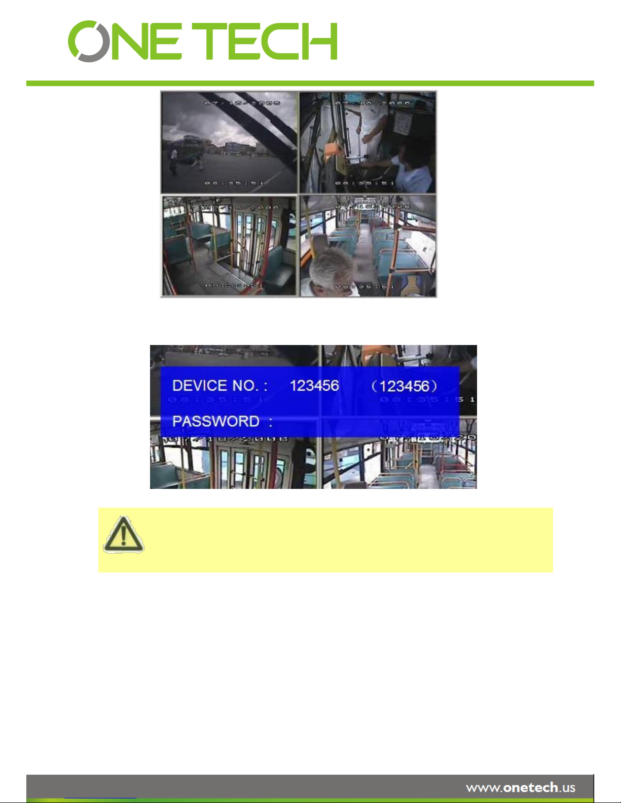
“Display only view” of the cameras is immediately available to be viewed in quad mode. Normally, the
power supply for MDVR is about 12V/3A, without any accessories.
Page 9 of 59
The MDVR GUI is semi-transparent. The user can setup the transparency percentage from the MDVR
GUI.
During the setting, the user can check the video from each camera as well.
Please make sure the user lock the removable hard disk case before connect the power for MDVR,
System Login for Setup
If password is disenable, press SETUP key on the handheld controller into the setup menu directly.
If password is enable, press LOGIN/LOCK OR ENTER key on the handheld controller, the setup menu
will appear.
Page 10 of 59
Please press SAVE in the GUI menu to make all the setting valid. The MDVR system will give the user a
remark if the user save the setting successfully. After the user modify the settings for the network, and
recording, the MDVR system will restart automatically after the system exits to Quad view
The MDVR will stop recording when enter into the MDVR configuration GUI.
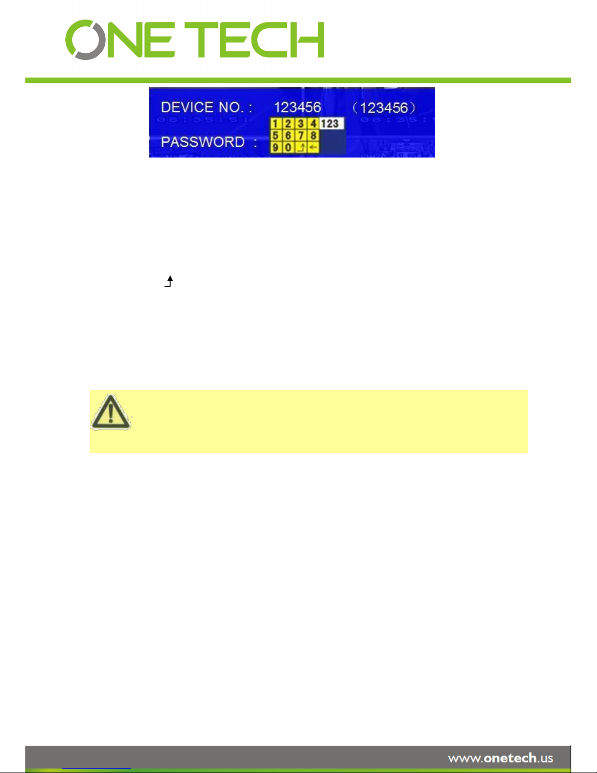
DEVICE NO.: The unit ID of MDVR. The user can setup the ID for the MDVR in the menu “REGISTER
INFORMATION”. After setting, the ID number will appear automatically on the login screen. It’s the
number in the bracket
PASSWORD: Enter the admin password or user password.
Keyboard: Press 【Enter】to use keyboard to type device ID and password.
1)0~9, number key, press【Enter】to select the number.
2)123: Input type shift key. (Number, capital, small letter)
3)【←】delete, 【 】Exit.
3 GUI CONFIGURATION
This part will show all the main functions for MDVR including SEARCH, SETUP and INFORMATION. SEARCH is
for searching all the regular video files and alarm files. SETUP is for all the configurations for MDVR including
recording, playback, event, network setup and INFORMATION displays the MDVR and accessory working status.
Page 11 of 59
3.1 SEARCH
3.1.1 REC. SEARCH
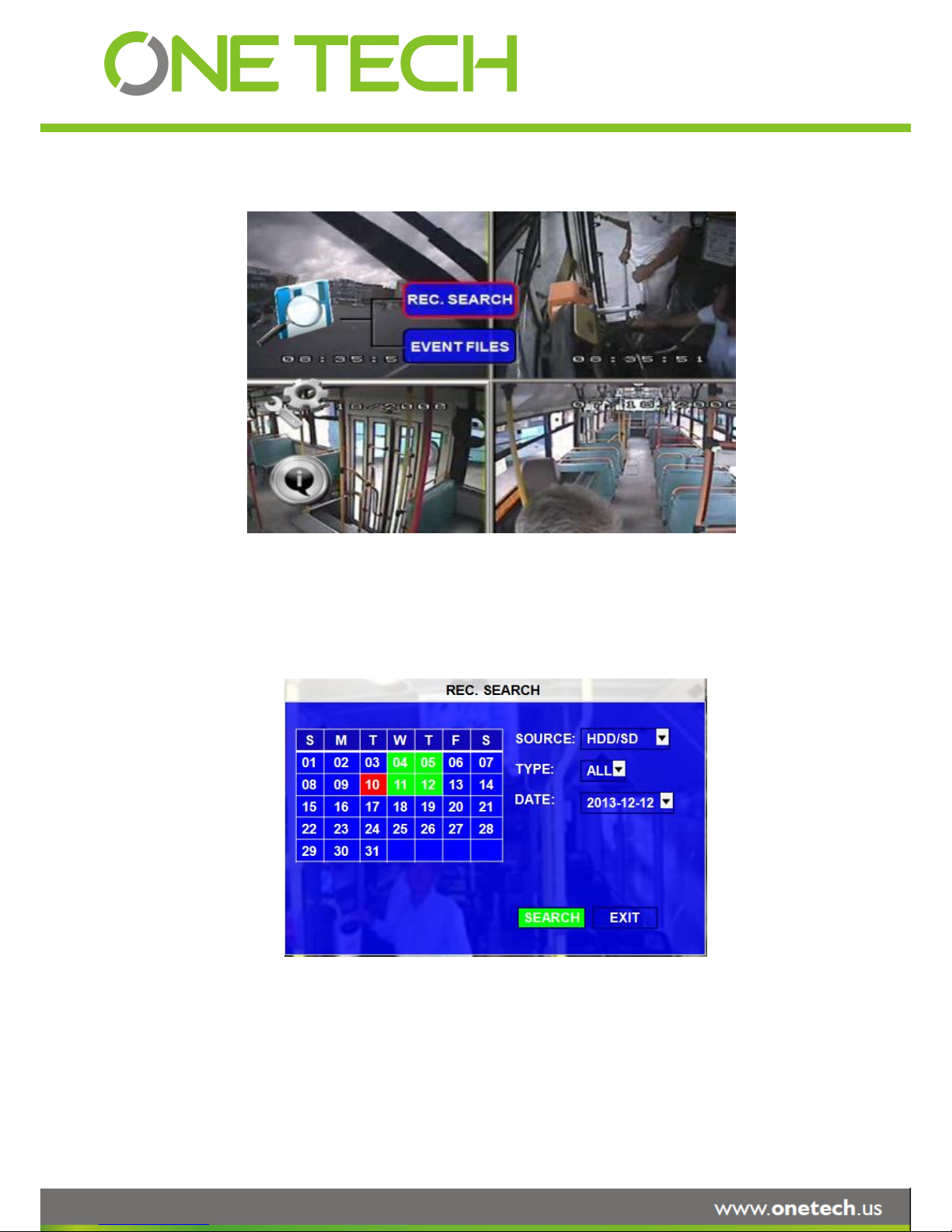
The user can search all the video files including normal files, alarm files by record date and file type and
storage source. Please select the REC.SEARCH and enter into following screen.
SOURCE:Source means which storage medium the recording files are stored in. Hard disk is the main
recording medium for MDVR X3A. But this model can support SD card for mirror recording as
well.
TYPE: The type of the file including all file, alarm file and normal file.
Page 12 of 59
Please active the lock files in EVENT menu. Only EVENT file can be locked since for end user the event
files are very important.
If the video file is locked, it cannot be deleted by HDD overwrite function. The user have to unlock the
files first and then HDD overwrite function will delete the files. Only the HDD format will delete the locked
DATE: MDVR system will display the current date automatically. The date with record files is indicated by
green. The date with alarm file is indicated by red. The date without video files is indicated by
background color.
Please press【SEARCH】to enter into the below menu
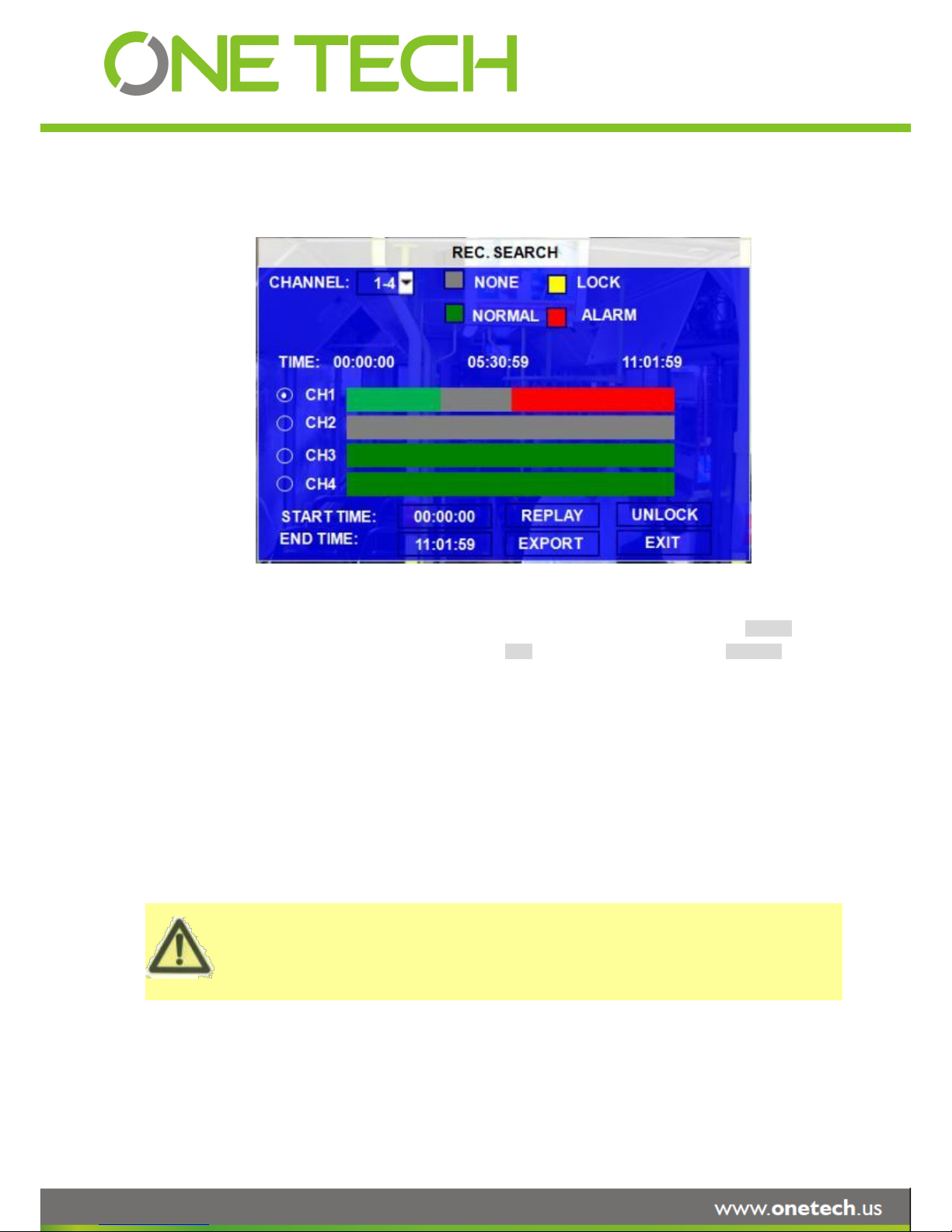
CHANNEL:As X3A supports 4CH, the user have to choose the channels from which channel the user want to
playback the video.
VIDEO FILE STATUS: GREY mean there is no video file in this channel or no video during this period, GREEN
means the file is normal recording file, RED means alarm file but not locked, YELLOW
means the locked alarm files.
START TIME and END TIME: The MDVR device can support the video clip function. This time schedule is for both
playback locally (playback on MDVR device) and export (export to thumb drive and
playback on PC by MINI Player or Ceiba software). The user have to choose the
channel first, and then setup the start time and end time for the video clip. For
example: if the user select the start time is 01:20:00 and the end time is 02:20:00,
then click REPLAY, the MDVR system will playback (local playback) the video file in
this period on this channel. During playback, the user can press ENTRE key to
show OSD information.
UNLOCK: the user have to select the channel first, and then unlock the files in certain period.
The user can export the MDVR video files to external storage device for playback easily. Just please input the
Page 13 of 59
If the user do not connect external storage device or the storage device is defective, the system will
display NO EXTERNAL STORAGE.
If the MDVR’s current video type is different with the setting for the MDVR record last time, the video file
can not playback, for example, the video type of record files is NSTC, but the MDVR recording system
now is changed to PAL, the user can’t playback the video file until the user change the video type to be
NSTC. Meanwhile the MDVR system will show the user the INFORMATION: PLEASE CHANGE THE
VIDEO TYPE TO PLAYBACK.
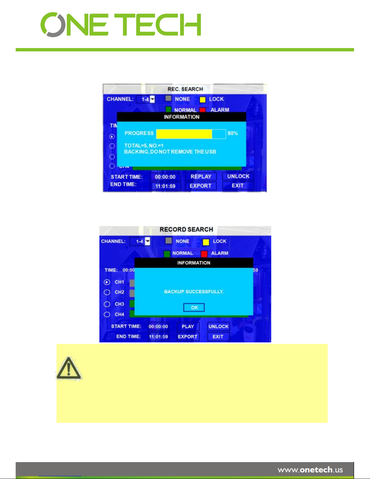
START TIME and END TIME for the video from certain channel for local playback, insert the external storage
device by USB port and then click EXPORT, the following screen will pop up. During backing up, the external
device is not allowed to be moved.
TOTAL: total quantity of the files that the user selected for back up.
NO.: The file number which is being copied to external thumb drive.
After successful backup, the following screen will pop up.
Page 14 of 59
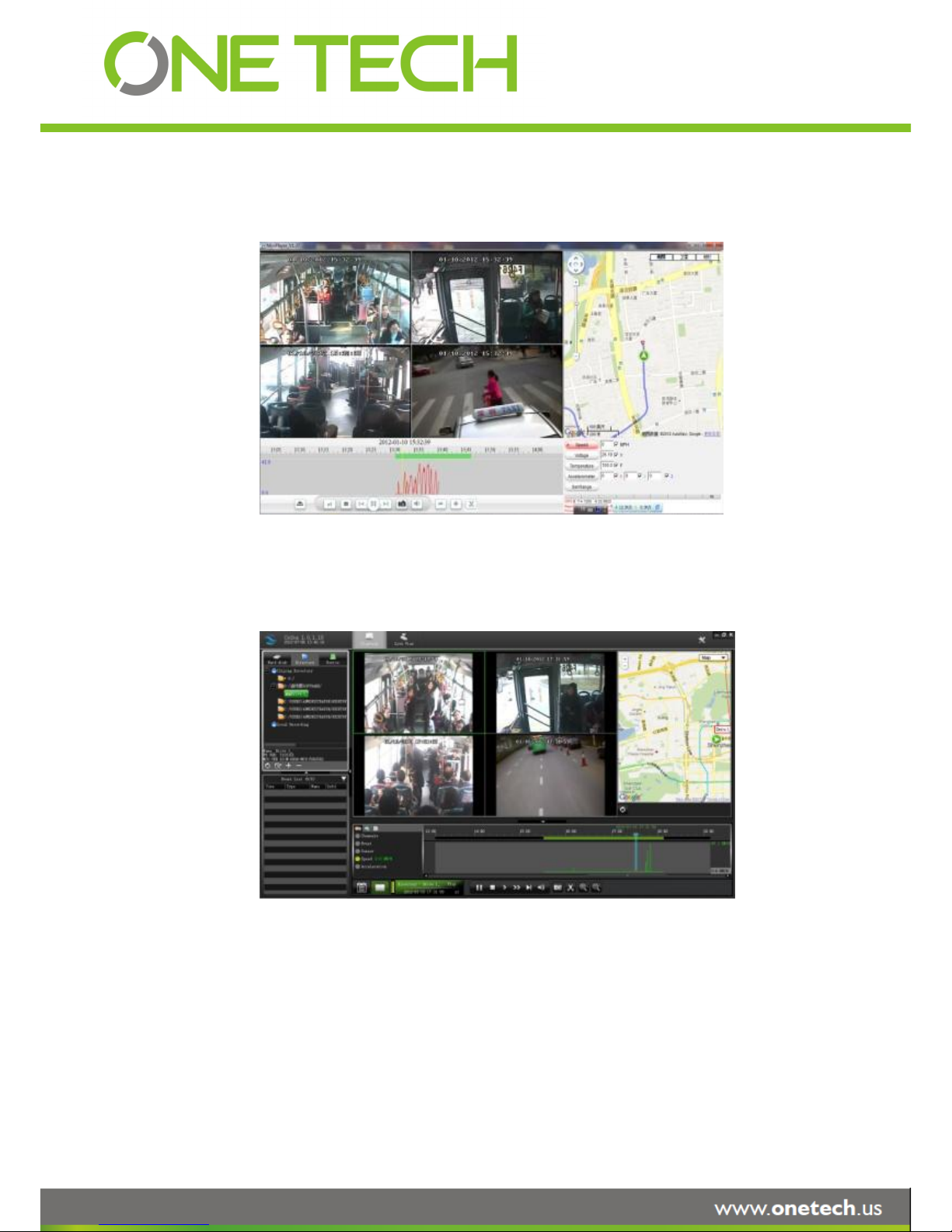
After backup, the user can copy the video clips to the computer for playback. This exported video file can be
playback easily by Stremax MINI player or Ceiba as following:
By Mini player:
By Ceiba software:
3.1.2 EVENT FILES
Search all the event LOG.
Page 15 of 59
MINI player is a very simple player developed by ONETECH. With it, user can playback the video files
including video, audio, GPS location, alarm information easily.
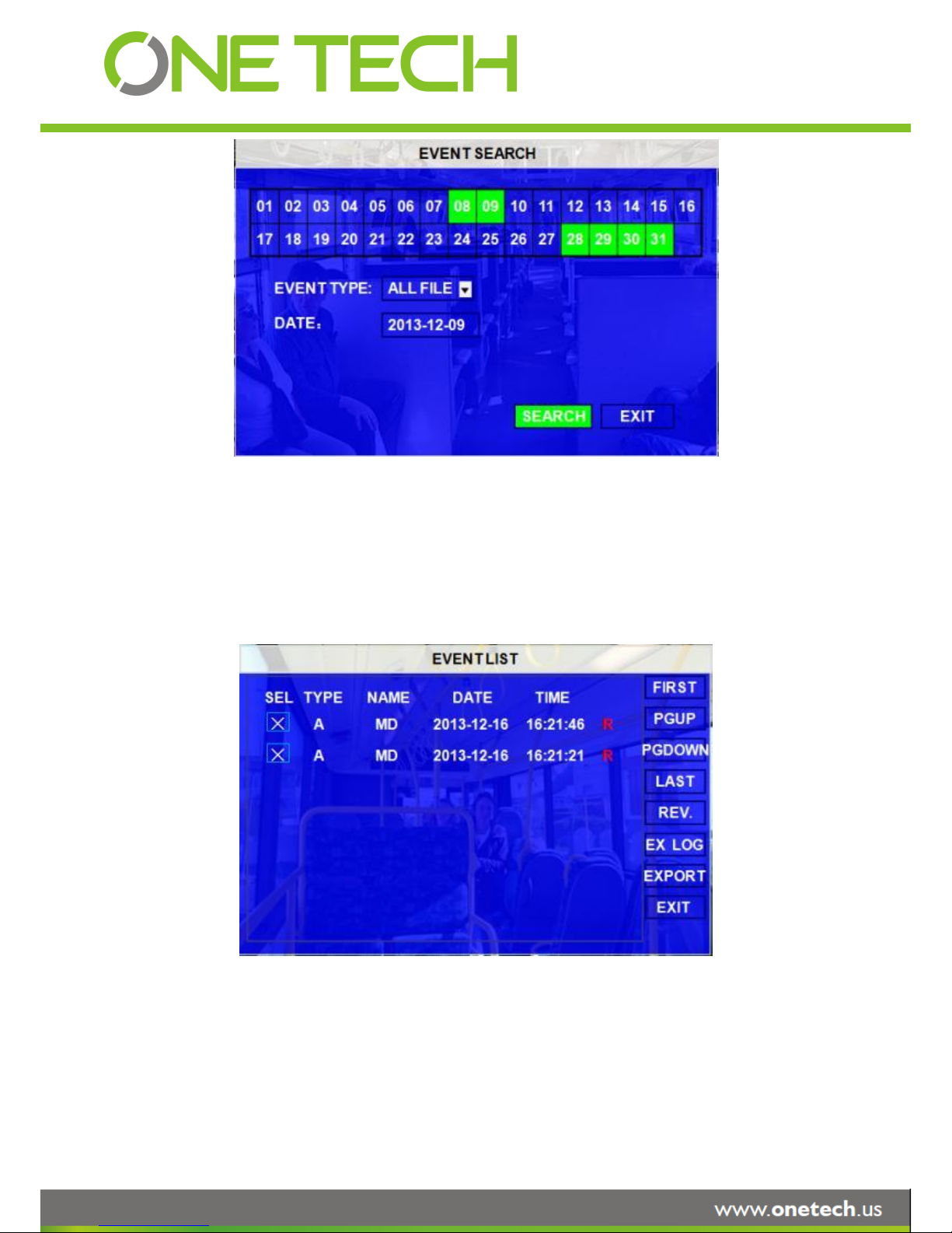
EVENT TYPE: The type of the alarm file including I&O ALARM/ACCELERATION/SPPED/TEMP ALARM/BD
ALARM/MD ALARM/VL ALARM. The user can please select different alarm type to search the
log and playback the corresponding video files.
DATE: MDVR system will display the current date automatically. Or the user can input the date the userrself by the
soft
keyboard.
Please press【SEARCH】to enter into the next menu listing out all the LOG depends on
FILE TYPE and DATE selected.
SEL: For selecting the LOG for backup. Please move the arrow key on remote control to select the LOG file that
need to back up. The file selected will be remarked by the icon ╳. Please press 【REV.】to for reversing
selection.
EVENT NAME: The event name is the one thatthe user setup for the events on the EVENT menu. But here just
Page 16 of 59

show the event OSD information (the abbreviation). The alarm includes such as video loss, I/O
sensor, alarm for over speed, low speed or high temperature and so on.
DATE: Display the date on which the alarm is triggered.
TIME: The start time when the alarm is triggered
REC: if there is an red “R” means it has the corresponding alarm video files.
REV.: Reversing selection. For example: If there are no any files are selected and the user select 【REV.】, all the
files are selected. If one file is selected and select 【REV.】, the others will be selected and the
originally-selected one will be unselected.
EX LOG: Export the selected LOG to external device by USB port on the front of MDVR.
EXPORT: Export the corresponding video if the event has the record file. If no related video file, the user will got a
remind information that no video file.
3.2 SETUP
Move arrow key to select SYSTEM and press ENTER. The MDVR setup screen will show the menu as below:
Page 17 of 59
3.2.1 SYSTEM
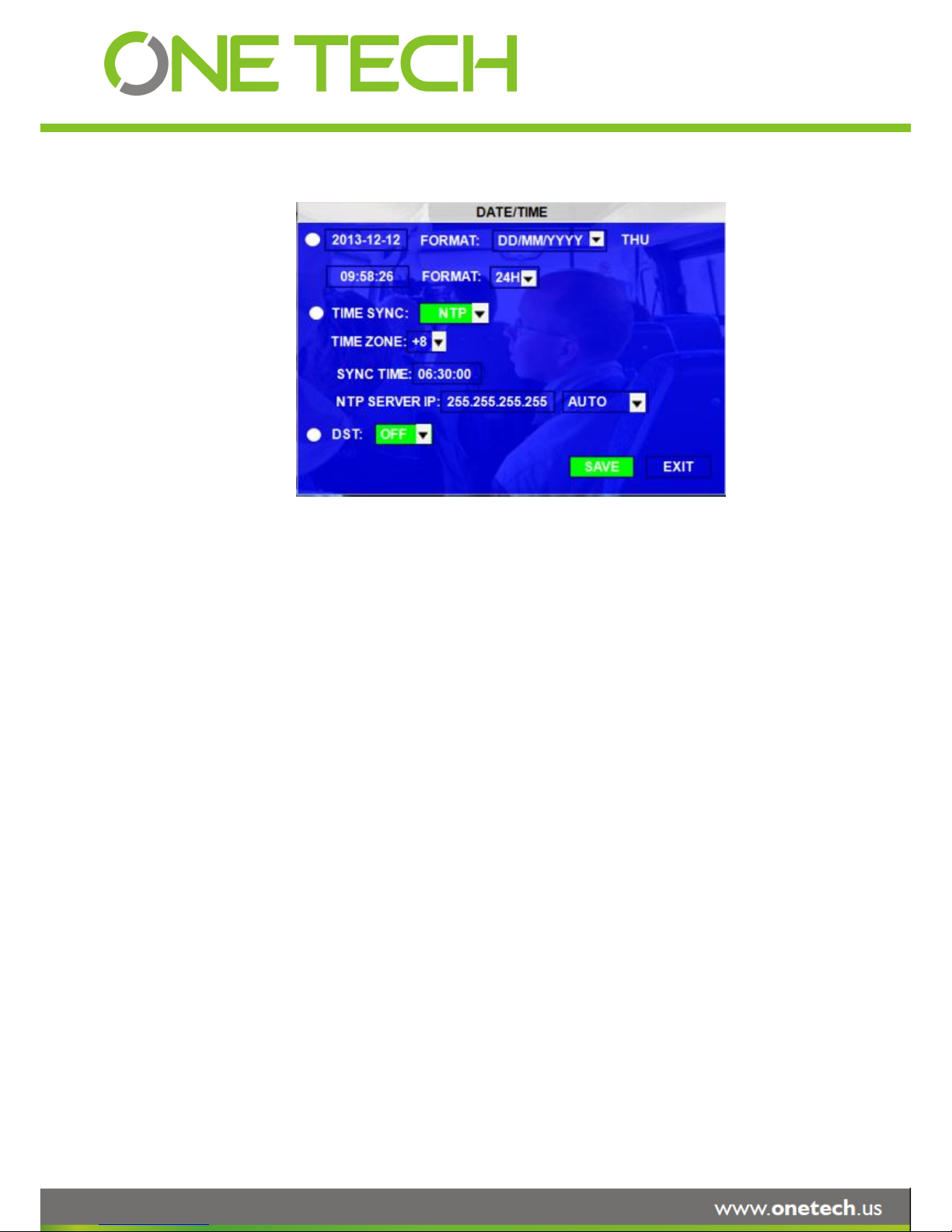
3.2.1.1 DATE/TIME
DATE FORMAT: Press ENTRE on remote control to select different format MM/DD/YYYY,
DD/MM/YYYY,YYYY-MM-DD
TIME FORMAT: 12H or 24H, Press ENTER to select different format.
TIME SYNC SOURCE: The system can adjust the time in different zone via either “GPS” or “NTP”.
A: While selecting the “GPS”, the MDVR device must have GPS connection (Should have GPS
module and antenna) and GPS must receive the signal. When the system time arrives the sync
time, MDVR unit will synchronize with GPS time once.
B: While selecting the “NTP” (Network Time Protocol), the device must have network access
connection and assign the NTP IP location.
TIME ZONE: Please choose the correct time zone for MDVR system.
SYNC TIME: This is the time when the unit will sync the system time every day. The method depends on the
setting on the TIME SYNC SOURCE option:
NTP SERVER IP: Input the server IP which can support NTP protocol, in order to allow the system can have time
synchronization through the network. [Example: "192.43.244.18", "129.6.15.28",
"211.22.55.116", "194.88.2.60"]
DST: Daylight Time. Only when it set on, the following option will available.
DST MODE: There are two modes: AUTO/MANUAL. Auto: According to the international DST, i.e.: valid only
between 2AM on Second Sun in March and 2AM on First Sun in NOV.
Page 18 of 59
 Loading...