

Page 1

SP.PMT INSTALLATION MANUAL
POLE MOUNT SYSTEM WITH TILT CAPABILITY v1.0
The One Systems SP.PMT Pole Mount System is a flexible suspension system designed to allow
specific One Systems loudspeakers to be mounted to pole structures while providing tilt aiming for
added flexibility. The only models approved for use with the SP.PMT are the ONE.SP6, ONE.SP8,
ONE.SP12D and ONE.SP12T speakers. !
NO OTHER LOUDSPEAKERS SHOULD BE SUBSTITUTED!
The following actions MUST be performed PRIOR to beginning the installation of the SP.PMT:!
" 1. This installation guide must be read and completely understood!
" 2. The instruction manual “Rigging and Suspension of One Systems Products” must be read
and understood.(This instruction manual is available at www.onesystems.com.)!
" 3. The manufacturer of the mounting pole MUST be consulted to verify the applicability of
the SP.PMT and ONE SYSTEMS loudspeaker model to the specific pole being used. The pole must
be capable of supporting the weight of the SP.PMT, the loudspeaker and all associated rigging and
ALSO meet all required safety factors specified by local and national codes and safe rigging
practices. !
" The weight of the SP.PMT is 4.16 kg (9.2 lb). The combined weight of the SP.PMT and a
ONE.SP6 is 12.16 kg (26.8 lb); the combined weight of the SP.PMT and a ONE.SP8 is 15.16 kg
(33.5 lb); the combined weight of the SP.PMT and a ONE.SP12D is 26.16 kg (57.7 lb); the combined
weight of the SP.PMT and a ONE.SP12T is 27.16 kg (59.9 lb). !
" 4. The SP.PMT and its attached speaker should be installed only by people experienced in
the overhead suspension of items and familiar with all applicable local and national codes
governing installation of these products and also governing the attachment of these types of
products to specific pole structures. !
" 5. The installer should be experienced with the use of stainless steel banding systems and
banding system tools. !
" 6. The SP.PMT is constructed with structural steel and is coated with a dual-layer, zinc-rich
powder coating. !
NOTE: The SP.PMT and the ONE.SP speaker models suspended by it are only designed for
use in inland, non-coastal applications (at least 16 km / 10 miles from salt air environments).
NOTE: Caution should be exercised when connecting One Systems speakers, suspension
hardware and pole structures (in regard to dissimilar metals). Compatible metals and
appropriate anode to cathode area ratios must be maintained. A structural engineer with
galvanic corrosion experience should be consulted prior to installation.
WARNINGS
One Systems, Inc © 2020, All Rights Reserved
Page 2
#
CAUTION: All structures outdoors are subjected to wind forces. These forces must be considered
when suspending any product outdoors. These forces must be considered when suspending any
product outdoors. It is necessary to know the “Effective Projected Area” (EPA) of the loudspeaker
and SP.PMT. See Appendix 1 of this installation guide for effective projected areas for each
speaker rated for use with the SP.PMT. Periodic inspections of the rigging, loudspeaker enclosure
and installation are strongly recommended. !
IMPORTANT NOTE: All products used in direct weather installations can be subjected to high
wind speeds. For wind speed exposure over 74 miles per hour (119.1 kilometers per hour, 64.3
knots), the loudspeaker enclosure, bracket, banding and Link assembly or safety must be
inspected for signs of damage or fatigue.
The SP.PMT may be used on round or square poles. The SP.PMT is designed for pole mounting
ONLY! DO NOT try wall mounting the SP.PMT.!
For square / rectangular poles the minimum flat dimension must be 3.75 inches (95.25 mm) at the
speaker’s mounting height and for round poles the minimum required diameter is 4 inches (101.6
mm) at the speaker’s mounting height. The SP.PMT was designed for use with the ONE.SP6,
ONE.SP8, ONE.SP12D and ONE.SP12T speaker models. NO SUBSTITUTIONS ARE ALLOWED!!
NOTE: One Systems does not imply suitability of specific poles or pole diameters. Each pole
must be verified by the pole manufacturer or others, as to the structural integrity of the pole for
use with the total load of the SP.PMT, the loudspeaker and all required safety factors.
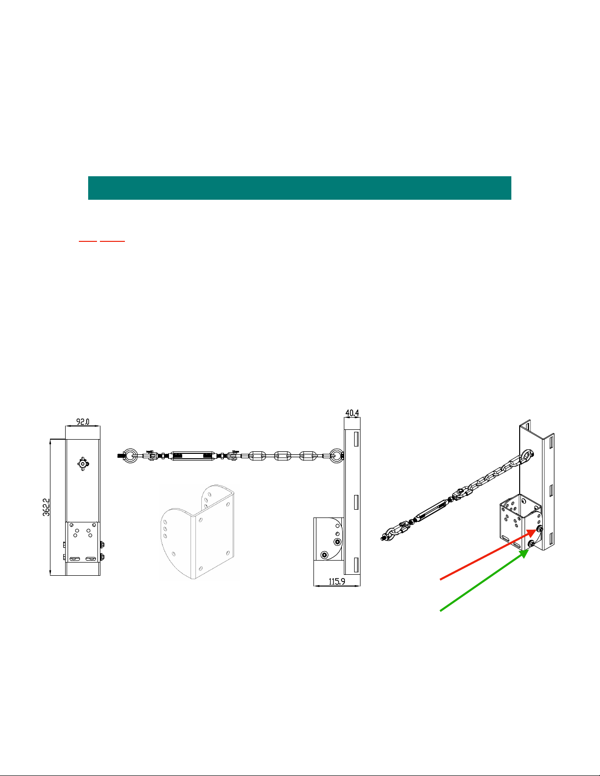
The SP.PMT is shown below in Figure 1. The SP.PMT allows a maximum down tilt of 35 degrees
adjustable
INSTALLATION OF THE SP.PMT
The SP.PMT consists of three parts: the pole bracket, the loudspeaker bracket and the Link. !
Prior to mounting the pole bracket to the pole, the speaker mount section should be removed. To
remove the speaker mount section, remove the pan pivot bolt and the pan aiming bolt.!
NOTE: There are M8 forged shoulder eyebolts supplied with the SP.PMT. Make certain that two of
them are mounted to the SP.PMT’s back plate (pole bracket) before attempting to mount the
bracket assembly to a pole structure!!
Tilt pivot bolt
Tilt aiming bolt
FIGURE 1
One Systems, Inc © 2020, All Rights Reserved
Page 3
NOTE: Instructions for mounting the Band-It bands and buckles are supplied by Band-It.
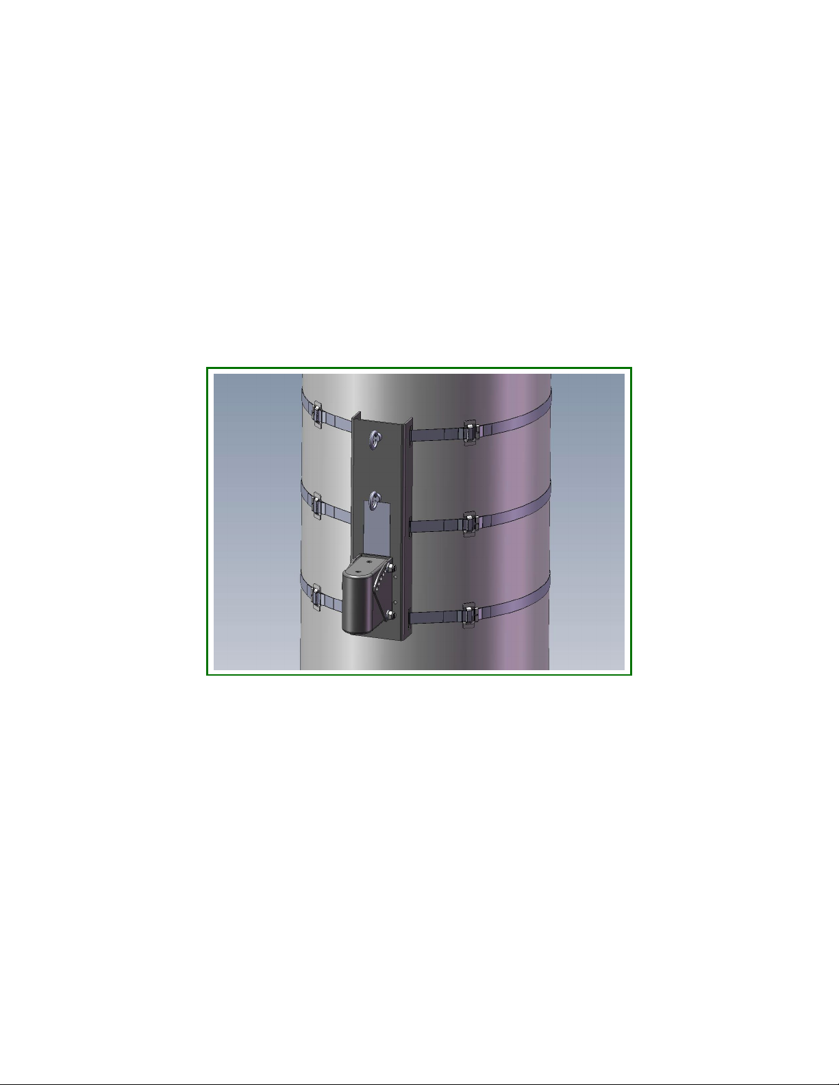
The SP.PMT has three slots on each side for mounting the pole bracket assembly on a pole. ALL
THREE slots MUST be used. Each slot MUST be DOUBLE WRAPPED (two INDEPENDENT bands
per slot!) using the specified Band-It straps and buckles ONLY! DO NOT substitute any other
straps. IT IS NECESSARY TO USE ALL MOUNTING SLOTS TO INSURE A SAFE AND SECURE
MATE TO THE ASSOCIATED SURFACE!!
IMPORTANT: It is REQUIRED that each of the three band slots be wrapped TWICE (TWO
INDEPENDENT SINGLE WRAPS PER SLOT). This should not be confused with “double
wrapping”, which is two wraps of the band through a single buckle. This means that a total
of 6 bands and 6 buckles are required for a single SP.PMT bracket. Two independent single
wraps per slot will insure a strong and secure mounting of the bracket to the pole. Insure
that the two buckles are separated from each other in each slot! The image below
illustrates the double wrapping required for each of the three slots.
5
IT IS CRITICAL THAT THE MATING SURFACE (Pole) BE CAPABLE OF SUPPORTING THE LOAD
OF THE SP.PMT BRACKET, THE LOUDSPEAKER AND ALL SUSPENSION HARDWARE, AS
WELL AS PROVIDING THE PROPER SAFETY FACTORS. DO NOT ATTEMPT TO SUSPEND THE
BRACKET AND LOUDSPEAKER UNTIL THE STRUCTURAL CHARACTERISTICS OF THE
MATING SURFACE (Pole) ARE UNDERSTOOD. DO NOT INSTALL THE POLE MOUNT BRACKET
AND LOUDSPEAKER IF THE MATING SURFACE (Pole) IS NOT CAPABLE OF SUPPORTING THE
ENTIRE ASSEMBLY WEIGHT, AS WELL AS PROVIDING THE REQUIRED SAFETY FACTORS!
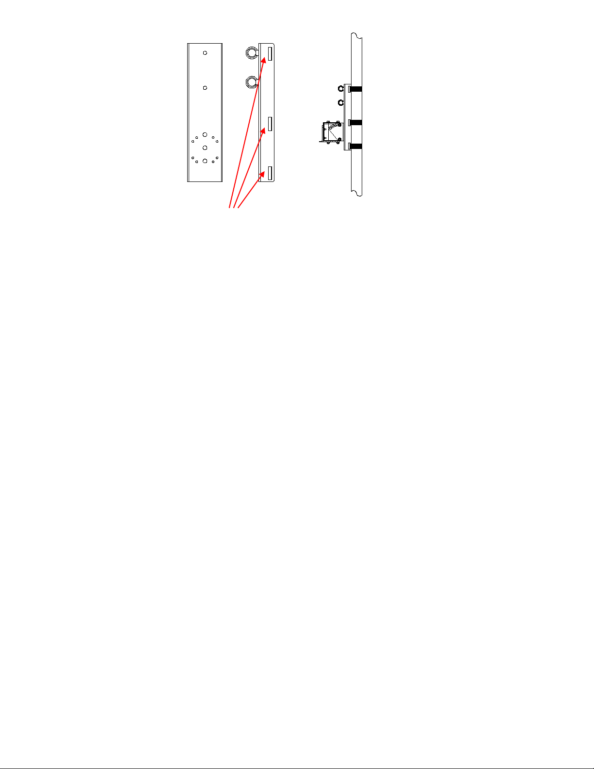
IMPORTANT: There are 3 slots indicated by the red arrows in the image below. Each of the 3
slots must be utilized to insure a secure mount to a pole. ALL 3 slots must use double wrapped
bands (Two independent bands wrapped in each slot)! The image below shows the band slots
and all these locations MUST be double wrapped (two independent band assemblies per slot as
per the image above.
FIGURE 2
One Systems, Inc © 2020, All Rights Reserved
Page 4
#
6
The red arrows indicate the 3 slots used to band the SP.PMT to a pole structure
6
Mount the SP.PMT bracket assembly to the pole at the desired height on the pole. The
bracket is mount to the pole using BAND-IT stainless steel bands. DO NOT SUBSTITUTE
bands of other material or other widths! There are 3 locations for banding on the SP.PMT
and ALL 3 slots MUST BE USED.
The required banding and buckle material for non-marine / non-coastal environments is:!
" " BAND-IT" # C206R9 stainless steel bands!
" " BAND-IT" # C25699 buckles!
" " BAND-IT" # C00169 tensioning tool!
The stainless steel banding is Type 201SS 0.030 inches (0.762 mm) thick and 0.750 inches
(19 mm) wide. These banding materials are only intended for use in “inland” environments
(which is all the SP.PMT and ONE.SP speakers are designed for).!
ANY QUESTIONS REGARDING THE BANDING SYSTEM SHOULD BE REFERRED
TO BAND-IT TECHNICAL SUPPORT
WARNING: Do NOT Substitute banding materials or banding dimensions.
Installation instructions from BAND-IT should be followed exactly. Operating instructions are
supplied with the tensioning tool. (ALL BAND-IT parts and tools must be purchased separately
from BAND-IT or from their distributors. These parts and tools are not supplied by and are not
available from One Systems). !
The stainless steel banding material, buckles, and tensioning tools are available from the following
sources (or through other distributors recommended by these sources):!
BAND-IT IDEX, Inc. !
4799 Dahlia Street!
Denver, CO 80216 USA!
800-525-0758!
FIGURE 3
One Systems, Inc © 2020, All Rights Reserved
Page 5

FELIX PONCE!
Calle Ignacio Zaragonza No. 8!
Colonia Ahuehuetes Atizapan 52953!
Edo. de Mexico!
(52) 555825 8502!
BAND-IT Company Limited!
Speedwell Industrial Estate!
Stavely, Nr. Chesterfield!
Derbyshire, S43 3 PF England!
Home Sales (44) 1246-479479!
Export Sales (44) 1246-479480!
BAND-IT Clamps (ASIA) Pte. Ltd.!
11 Second Chin Bee Road!
Singapore 618777!
65-62658853!
BAND-IT Shanghai Sales Office!
207 Room!
Wanbao International Business Centre!
#660 Xinhua Road!
Shanghai, China 200052!
021-62826348-308!
1. The loudspeaker bracket should be attached to the loudspeaker’s U-Bracket (ONE.SP
speaker’s U-Bracket) using the supplied stainless steel bolts and washers. DO NOT
SUBSTITUTE ANY PARTS.!
2. The combination of the U-Bracket and the loudspeaker bracket from the pole mount should
be attached to the speaker. !
3. The loudspeaker with its U-Bracket attached may now be attached to the pole bracket.!
USE EXTREME CAUTION! The loudspeaker and bracket are heavy and it is likely that the
desired mounting location is high off the ground. This process should never be attempted by a
single person.!
TWO OR MORE PEOPLE ARE REQUIRED TO MOUNT THE LOUDSPEAKER ENCLOSURE
WITH ITS U-BRACKET ATTACHED TO THE POLE BRACKET! Safety harnesses should
always be worn when working from an elevated platform.
4. First, insert the metric bolt into the tilt pivot bolt location shown in Figure 1 and secure, but
do not fully tighten using the supplied nylon insert nut.!
One Systems, Inc."" www.onesystems.com tel:+1-615-823-1655 fax: +1-615-261-1429
One Systems, Inc © 2020, All Rights Reserved
Page 6
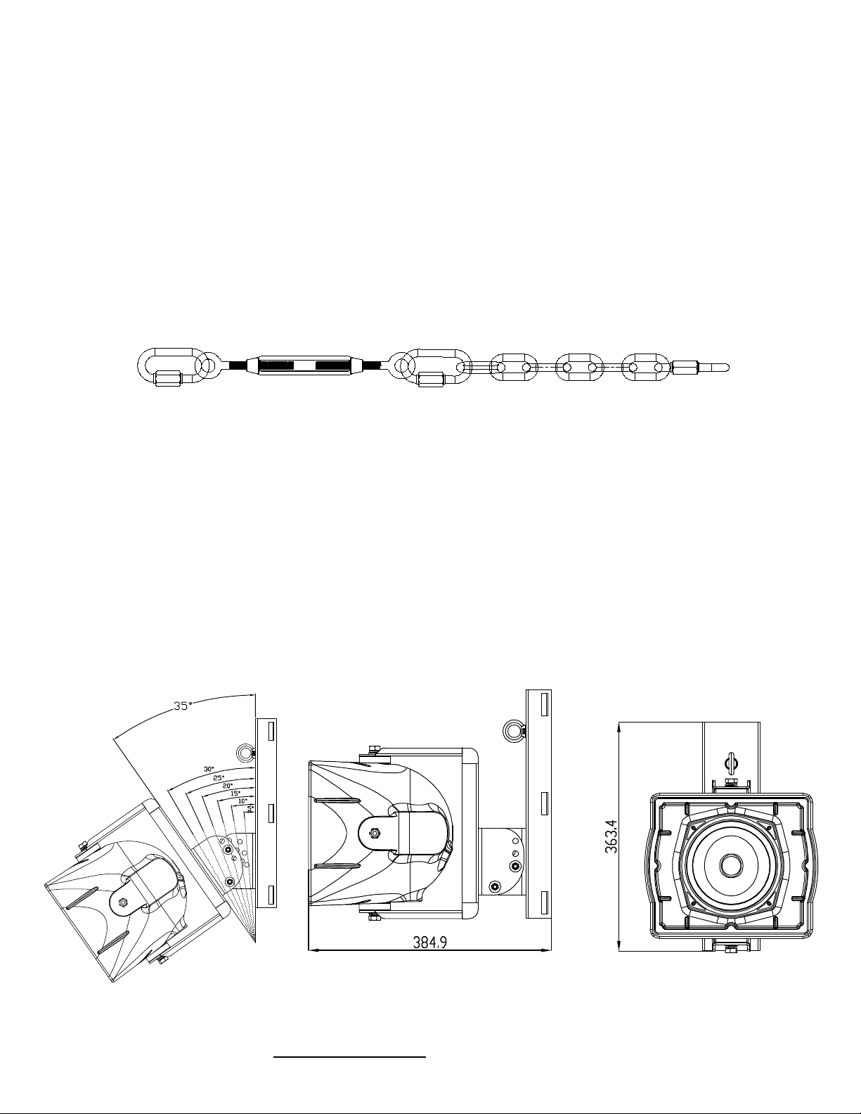
5. Next, insert the tilt bolt into the proper slot. The SP.PMT allows the loudspeaker to be
oriented from a 0 degree down tilt to a maximum down tilt of 35 degrees adjustable in 5 degree
increments. After being positioned, the bolts should be tightened using the supplied nylon
insert nuts and washers. !
UNDER NO CIRCUMSTANCES SHOULD THE LOUDSPEAKER’S DOWN TILT EXCEED 35
DEGREES FROM VERTICAL!
After the loudspeaker and U-Bracket are attached to the main bracket, the Link assembly must
be installed. The Link (see Figure 4 below) consists of stainless steel quick links, a stainless
steel turnbuckle, and several links of stainless steel chain. !
THE SP.PMT SHOULD ONLY BE INSTALLED USING THE LINK!
CAUTION: DO NOT REMOVE THE PAN PIVOT BOLT AFTER INSTALLATION!
The pan angle may be adjusted by removing the tilt aiming bolt, setting the desired angle and
then re-inserting the bolt. After the tilt angle is set, positioning of the Link offers additional
aiming angles. Positioning the Link on the lower position will provide support for short aiming
angles (0 - 15 degrees) and positioning it on the higher position will provide support for
greater downward tilt angles (20 - 35 degrees). !
When choosing the tilt angle, also remember that One Systems recommends a downward
angle of at least 5 degrees to help minimize moisture intrusion into the loudspeaker’s
enclosure.
ONE.SP6 mounted on the SP.PMT
FIGURE 5
One Systems, Inc © 2020, All Rights Reserved
One Systems, Inc."" www.onesystems.com tel:+1-615-823-1655 fax: +1-615-261-1429
FIGURE 4
Page 7
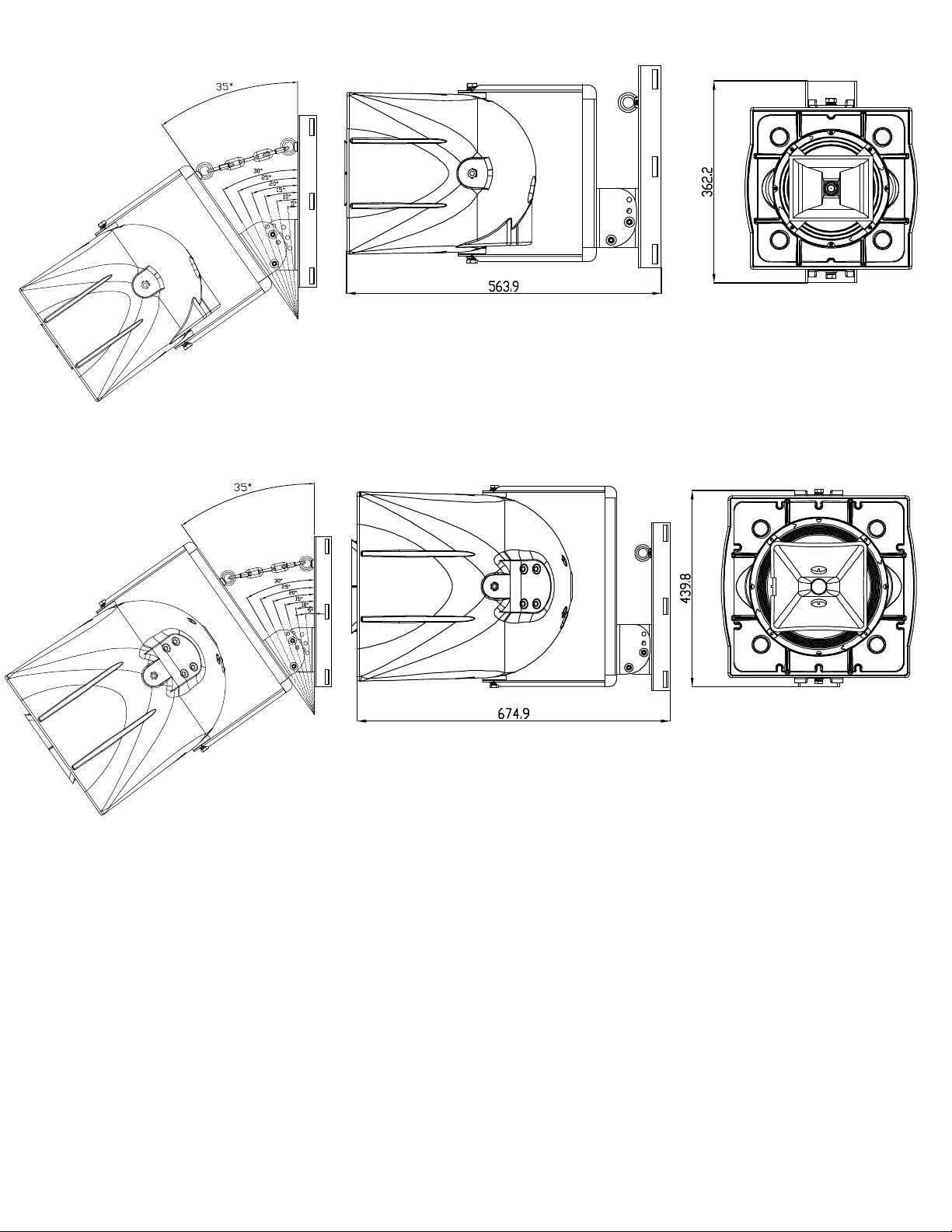
ONE.SP8 mounted on the SP.PMT
ONE.SP12 mounted on the SP.PMT
FIGURE 5
Page 8

APPENDIX 1
Projected Area Values
The values below should be supplied to the specific pole manufacturer for safety calculations.
These values were determined by adding the projected areas of the high frequency horns, the
woofer cones and ports to the cross sectional area of the front of each speaker listed below.
The Effective Projected Area (EPA) will vary based on wind direction. The values shown are for
wind directions directly into the front of the enclosure and represent maximum values.!
ONE.SP6 - - - 112.22 in2 / 724 cm2 (using drag coefficient 1.2)!
ONE.SP8 - - -160.11 in2 / 1,033 cm2 (using drag coefficient 1.2) !
ONE.SP12D / ONE.SP12T - - - 318.83 in2 / 2,057 cm2 (using drag coefficient 1.2)!
One Systems, Inc © 2020, All Rights Reserved
One Systems, Inc."" www.onesystems.com tel:+1-615-823-1655 fax: +1-615-261-1429
 Loading...