

Page 1
© 2020 One Systems, Inc, All Rights Reserved
Pan & Tilt Brackets Installation Guide
PT38.M and PT76.M
The PT76.M and PT38.M are flexible and easy to install brackets designed to allow
specific One Systems loudspeaker models to be mounted to walls or other flat
surfaces. The only products approved for use with the PT38.M and PT76.M are listed
as follows:
PT38.M
108.HTC!
108.STC!
108.HSB!
108.HTC!
208.HTC
PT76.M
112.HTH!
118.HSB (See appendix 2)!
212.HC!
312.HC!
CFA2.HTH
1
PT-38M and PT-76M
January 2015
1
NOTE: The PT38.M and PT76.M were designed for installation on flat surfaces
ONLY! The PT76.M and PT38.M may NOT be pole mounted. One Systems offers the
PM3.M and the PM4.M for pole mounting applications of the referenced
loudspeakers.
PT38.M
PT76.M
1
NO OTHER LOUDSPEAKERS SHOULD BE SUBSTITUTED!
Page 2

The following actions MUST be performed PRIOR to beginning the installation of
the PT76.M or PT38.M:!
1. This installation guide must be completely read and understood!
2. The instruction manual “Rigging and Suspension of One Systems " "
" Products”must be read and understood. (This instruction manual is " "
" available along with other technical papers at www.onesystems.com ""
" under the “Documentation” tab!
" 3. The structure of the mating surface MUST be capable of supporting the "
" combined weight of the pan and tilt bracket, the loudspeaker and all ""
" associated rigging; and must satisfy the required safety factors specified
" by local and national codes, as well as safe rigging practices. The " "
" PT76.M weighs 11.4 kg / 25.1 lb. The PT38.M weighs 4.5 kg / 9.9 lb.!
" 4. The PT76.M and PT38.M pan and tilt brackets should be installed only "
" by someone experienced in the overhead suspension of items. They " "
" should be familiar with applicable local/national codes governing the " "
" installation of these types of products and those governing the "" "
" attachment of these types of products to specific structures. !
NOTE: Caution should be exercised when connecting One Systems Marine
grade products and Marine grade rigging to other metallic, non-316 grade
stainless steel surfaces (dissimilar metals). The potential for galvanic
corrosion is high in marine environments where the One Systems Marine
grade enclosures and rigging are specified or required. Compatible metals
and appropriate anode to cathode area ratios must be maintained. A
structural engineer with galvanic corrosion experience should be consulted
prior to installation of marine grade products, or ANY One Systems products
in marine environments.
CAUTION: All structures outdoors are subjected to wind forces. These forces must
be considered when suspending any product outdoors. It is necessary to know the
“Effective Projected Area” (EPA) of the loudspeaker prior to installation of the
loudspeaker and the PT76.M or PT38.M. See Appendix 1 of this installation manual
for effective projected areas for each enclosure rated for use with the PT76.M and
PT38.M. Periodic inspections of the rigging, loudspeaker enclosure and installation
are strongly recommended.
© 2020 One Systems, Inc, All Rights Reserved
2
WARNINGS!
Page 3
IMPORTANT NOTE: All products in direct weather installations can be subjected
to high wind speeds. For wind speed exposure over 74 miles per hour (119.1
kilometers per hour, 64.3 knots) the loudspeaker enclosure, bracket, Link
assembly and any secondary safety (not supplied) must be inspected for signs of
damage or fatigue!
INSTALLATION
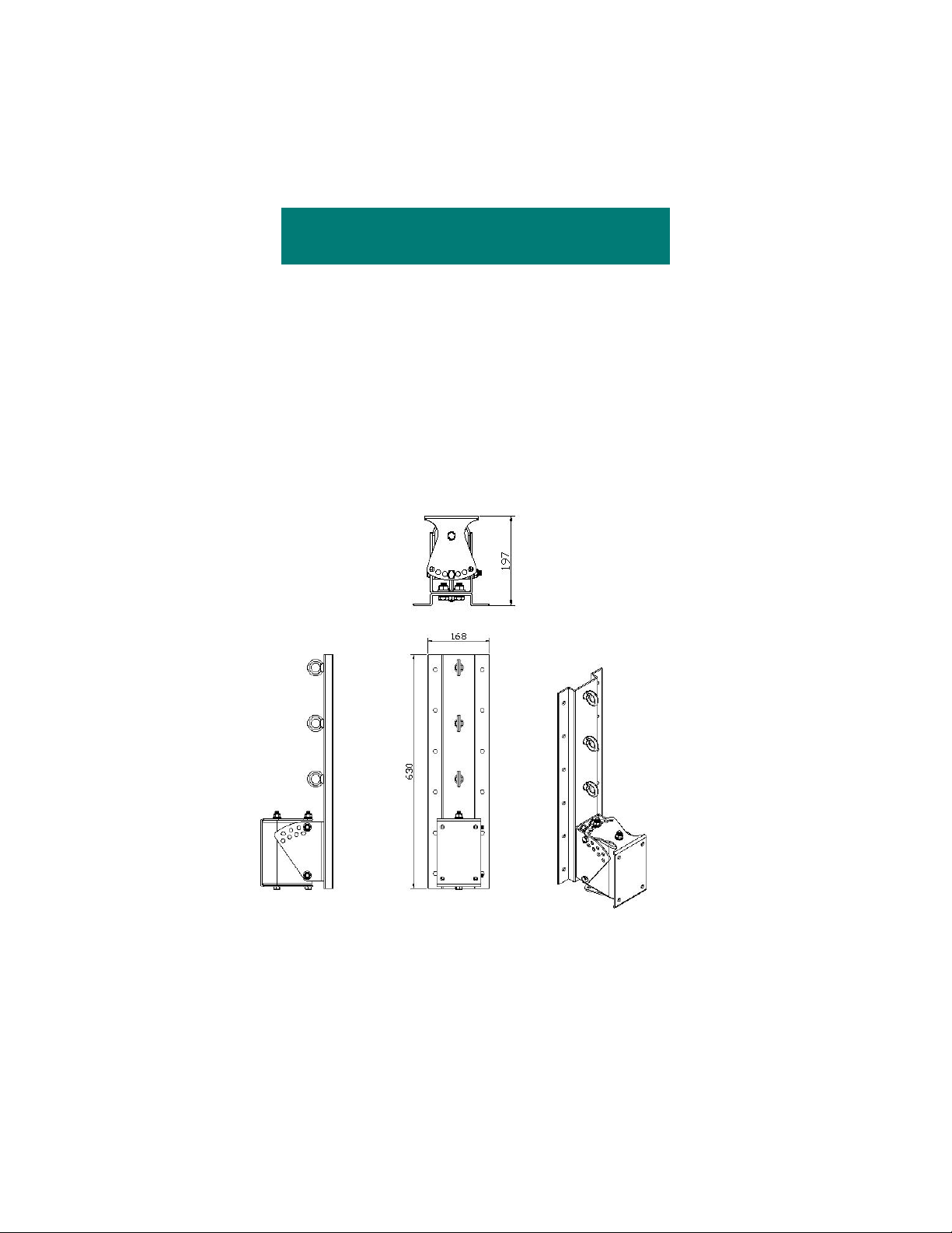
The PT76.M and PT38.M consist of three parts: the wall bracket, the loudspeaker
bracket, and the Link. The PT76.M wall bracket and loudspeaker bracket are
shown in Figure 1. Figure 1a shows the wall bracket portion of the PT76.M. The
PT76.M bracket allows the loudspeaker to be oriented from a 0 degree down tilt
to a maximum down tilt of 35 degrees adjustable in 5 degree increments. The
PT38.M allows a maximum down tilt of 40 degrees adjustable in 8 degree
increments.
INSTALLATION
Figure 1
© 2020 One Systems, Inc, All Rights Reserved
3
Page 4
4
Figure 1a
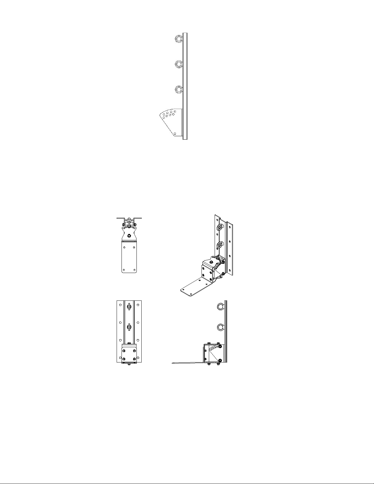
The PT38.M wall bracket and loudspeaker bracket are shown in Figure 2 below:
4
Figure 1a
Figure 2
Prior to mounting the wall bracket to the wall, the speaker mount section
should be removed. See Figures 2a and 2b.
© 2020 One Systems, Inc, All Rights Reserved
4
Page 5

The wall bracket section should now be mounted to the wall surface. The PT76.M
has 12 mounting holes and the PT38.M has 8 mounting holes for allowing
fasteners to attach the bracket and loudspeaker assembly to the mating surface.!
IT IS NECESSARY TO USE ALL MOUNTING HOLES TO INSURE A SAFE AND
SECURE ATTACHMENT TO THE ASSOCIATED SURFACE! (12 for the PT76.M
and 8 for the PT38.M).
All fasteners associated with the mounting of the Pan / Tilt bracket and
loudspeaker assembly to the mating surface are the responsibility of others.
The design and structural capacity of mating surfaces (such as walls) vary
greatly and specific fasteners are designed for use with specific mating surfaces.
One Systems does not recommend any specific mating fasteners and strongly
urges the installer to consult with one experienced in suspension of products
from the specific mating surfaces and the appropriate choice of fasteners for
those specific surfaces.!
The wall bracket section should be secured firmly to the mating surface using the
appropriate fastening system. The fastening system should be determined by the
structure and construction of the mating surface.!
IT IS CRITICAL THAT THE MATING SURFACE BE CAPABLE OF SUPPORTING
THE LOAD OF THE PT BRACKET, THE LOUDSPEAKER AND ALL SUSPENSION
HARDWARE, AS WELL AS PROVIDING THE PROPER SAFETY FACTORS. DO
NOT ATTEMPT TO SUSPEND THE BRACKET AND LOUDSPEAKER UNTIL THE
STRUCTURAL CHARACTERISTICS OF THE MATING SURFACE ARE
UNDERSTOOD. DO NOT INSTALL THE PT BRACKET AND LOUDSPEAKER IF
THE MATING SURFACE IS NOT CAPABLE OF SUPPORTING THE ENTIRE
ASSEMBLY WEIGHT, AS WELL AS PROVIDING THE REQUIRED SAFETY
FACTORS!!
After the PT wall section of the bracket is securely mounted to the mating
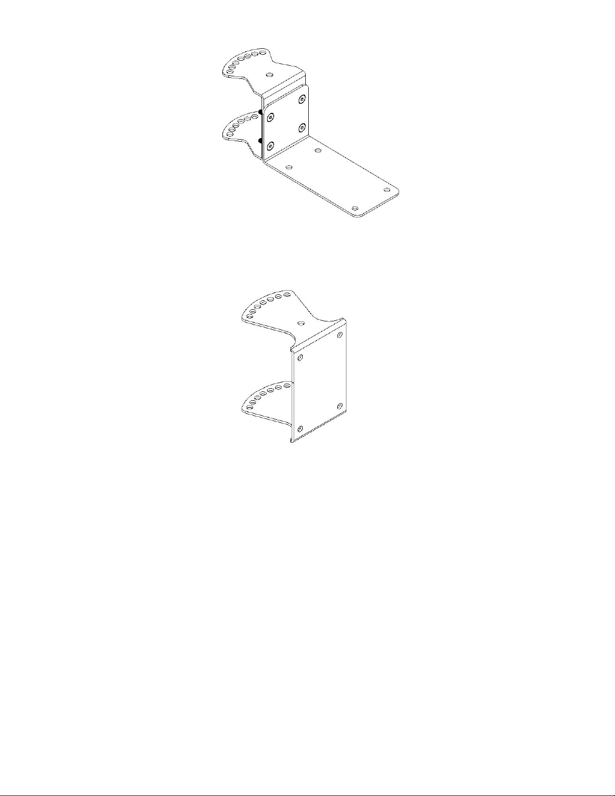
surface, the loudspeaker section should be mounted to the loudspeaker using the
fasteners supplied. (DO NOT SUBSTITUTE FASTENERS) The loudspeaker mount
section of each bracket is shown in Figures 2a and 2b.!
NOTE: If the PT76.M is being used with the One Systems 118.HSB, see
Appendix 2 at the end of this document!
© 2020 One Systems, Inc, All Rights Reserved
5
Page 6
6
Figure 2a: PT38.M speaker mount bracket
6
Figure 2b: PT76.M speaker mount bracket
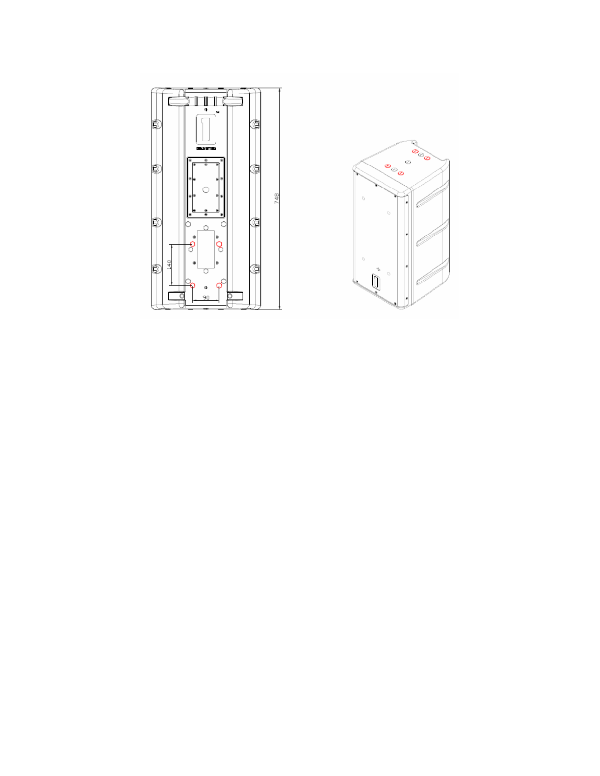
The PT76.M mounts to the rear of all large-format Platinum Series enclosures,
(except for the 108.HTH, 108.HTC and 208.HTC), using the 140 mm x 90 mm
M10 locations as shown in Figure 2c. The PT38.M mounts to the bottom of the
108.HTH, 108.HSB, 108.HTC, 108.STC or 208.HTC as shown in Figure 2c using
the M8 locations. The mounting locations are highlighted in red.!
DO NOT SUBSTITUTE MOUNTING LOCATIONS!
Additionally, there are forged shoulder eyebolts supplied in the PT kits, 4 x M10
eyebolts for the PT76.M and 3 x M8 eyebolt for the PT38.M. One of these
eyebolts must be installed in the top, rear portion of the enclosure. Make sure
that the eyebolt is seated on the surface of the enclosure.
© 2020 One Systems, Inc, All Rights Reserved
5
Page 7
7
Figure 2c
The loudspeaker and loudspeaker section of the bracket may now be joined to
the wall section and the required pan and tilt angles selected. This is a two
person job and extreme care should be exercised to avoid serious injury.!
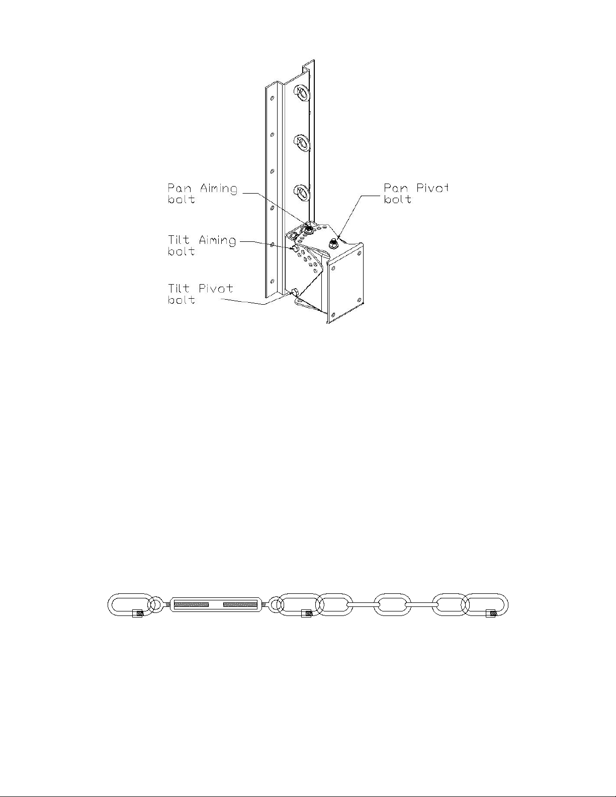
The pan pivot bolt should be inserted first and secured but not completely
tightened using the nylon insert nuts supplied. The pan pivot bolt is shown
below in Figure 2d. Then the pan aiming bolt should be inserted and nylon insert
nuts applied. Then the tilt axis bolts should be tightened.!
CAUTION: DO NOT REMOVE THE PAN PIVOT BOLT!
Next the pan angle may be adjusted by removing the pan aiming bolt, but NOT
the pan pivot bolt, and setting the desired pan angle and then re inserting the
bolt.!
The tilt angle may be adjusted my removing the tilt aiming bolt. DO NOT remove
the tilt pivot bolt!!
Once both the tilt and pan angles are set, make sure that all bolts are tight and
secure.
© 2020 One Systems, Inc, All Rights Reserved
6
Page 8
8
Figure 2d
UNDER NO CIRCUMSTANCES SHOULD THE LOUDSPEAKER’S DOWNWARD
TILT EXCEED 35 DEGREES FROM VERTICAL FOR THE PT76.M. THE MAXIMUM
DOWNWARD TILT IS 40 DEGREES FOR THE PT38.M.!
INSTALLING THE LINK
Figure 3 is an illustration of the Link assembly. This assembly MUST be used
whenever the PT76.M or PT38.M is being installed. Each pan and tilt bracket is
supplied with a Link assembly.!
SEE SECTION 5 OF THIS MANUAL FOR DETAILS ON THE PROPER
MOUNTING OF THE LINK ASSEMBLY!
8
Figure 2d
Figure 3
© 2020 One Systems, Inc, All Rights Reserved
6
Page 9

USE EXTREME CAUTION! The loudspeaker is heavy and it is likely that the desired
mounting location is high in the air. This process should never be attempted by a
single person.!
TWO OR MORE PEOPLE ARE REQUIRED TO MOUNT THE LOUDSPEAKER
ENCLOSURE TO THE WALL, OR POLE, AND PT bracket. Safety harnesses should
always be worn when working from an elevated platform.!
SECTION 5 LINK ASSEMBLY
Now the Link must be installed.!
INSTALLING the Pan and Tilt Brackets WITHOUT THE LINK IS NOT ALLOWED!
The Link (see Figure 3) consists of stainless steel quick links, a stainless steel
turnbuckle, and several links of stainless steel chain. The use of the chain pieces
and quick links with the turnbuckle is based on the tilt angle of the enclosure. The
turnbuckle should always be used.!
DO NOT SUBSTITUTE ANY PART OF THIS LINK ASSEMBLY!
The Link should be tightened by rotating the turnbuckle until there is very slight
tension on the Link assembly. DO NOT OVER-TIGHTEN THE TURNBUCKLE!
Warning: If the turnbuckle assembly is turned and the loudspeaker enclosure’s
angle begins to change (if the down tilt angle begins to move toward 0 degrees
vertical) then the turnbuckle has been OVER-TIGHTENED. Turn the turnbuckle
until the down tilt angle is set by the M10 thru bolt on the bracket but there is
still very slight tension on the turnbuckle. DO NOT OVER-TIGHTEN THE
TURNBUCKLE! ONLY VERY SLIGHT TENSION IS REQUIRED!
The purpose of the Link is to provide very slight support for the main tilting bracket
at the bottom of the assembly.!
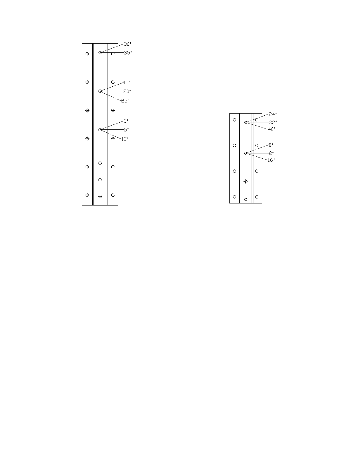
The back plate sections of the PT76.M and PT38.M have eyebolts attached to
them. There are 3 eyebolts on the back plate section of the PT76.M and 2 eyebolts
on the back plate section of the PT38.M. Figure 7 illustrates which eyebolt should
be used for each down tilt angle.
© 2020 One Systems, Inc, All Rights Reserved
7
Page 10
10
Figure 7
PT76.M PT38.M
Make sure to use the appropriate combination of Link parts to insure proper
connection between the PT bracket assembly and the specific One Systems
speaker enclosure. The required combination of Link parts is determined by the
down tilt angle of the enclosure.!
The assembly may be configured with any combination of turnbuckle, chain link
sections and quick link in order to achieve the proper tension on the system, but
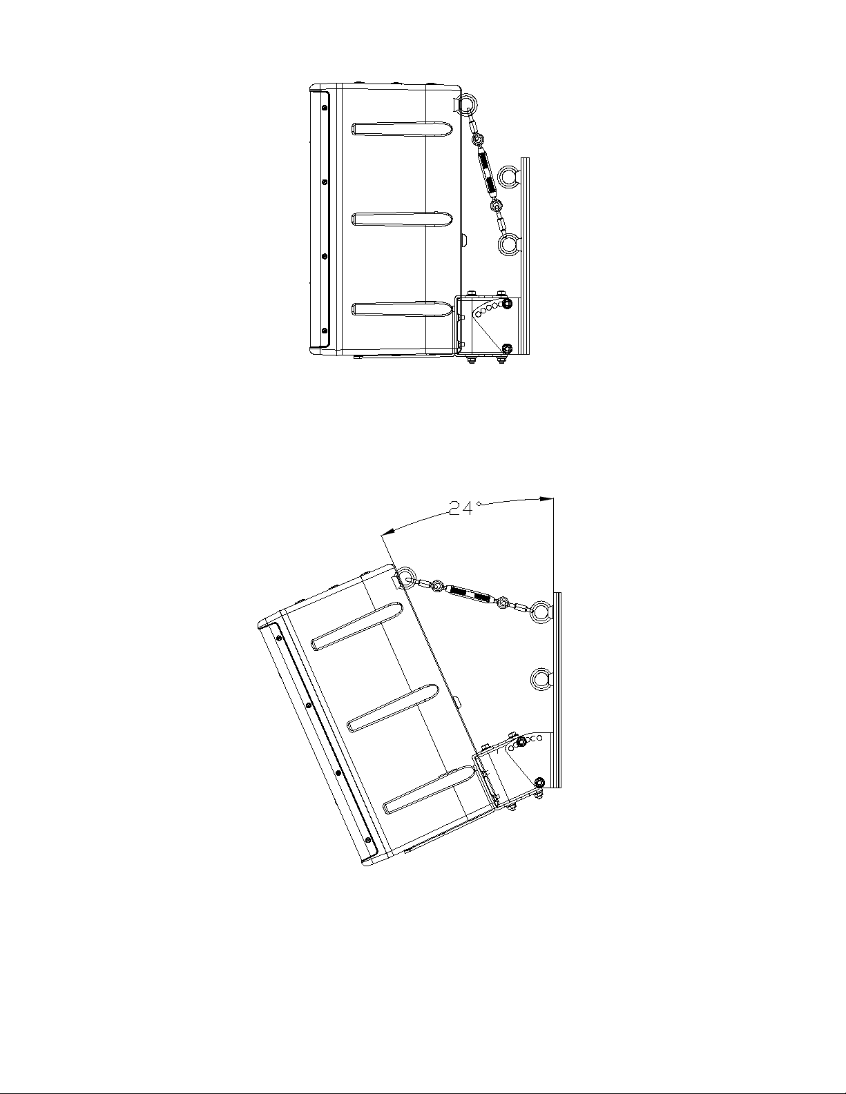
the turnbuckle must always be used. Figures 8a, 8b, and 8c show a 108.HTH
and PT38.M at vertical, 24 degrees and 40 degrees using the eyebolt positions
shown in Figure 7. Note that Figure 8a and 8b use the same link and turnbuckle
combination but different eyebolt locations and the Figure 8c uses chain
sections as well as the quick links and the turnbuckle.
© 2020 One Systems, Inc, All Rights Reserved
8
Page 11
11
Figure 8a
Figure 8a represents the Link assembly with the enclosure in a vertical orientation
and the Link using the lower eyebolt position
11
Figure 8a
Figure 8b
Figure 8b represents the Link with the enclosure in a 24-degree tilt. The Link is
using the top eyebolt and the turnbuckle has been adjusted to provide mild
tension.
© 2020 One Systems, Inc, All Rights Reserved
9
Page 12
12
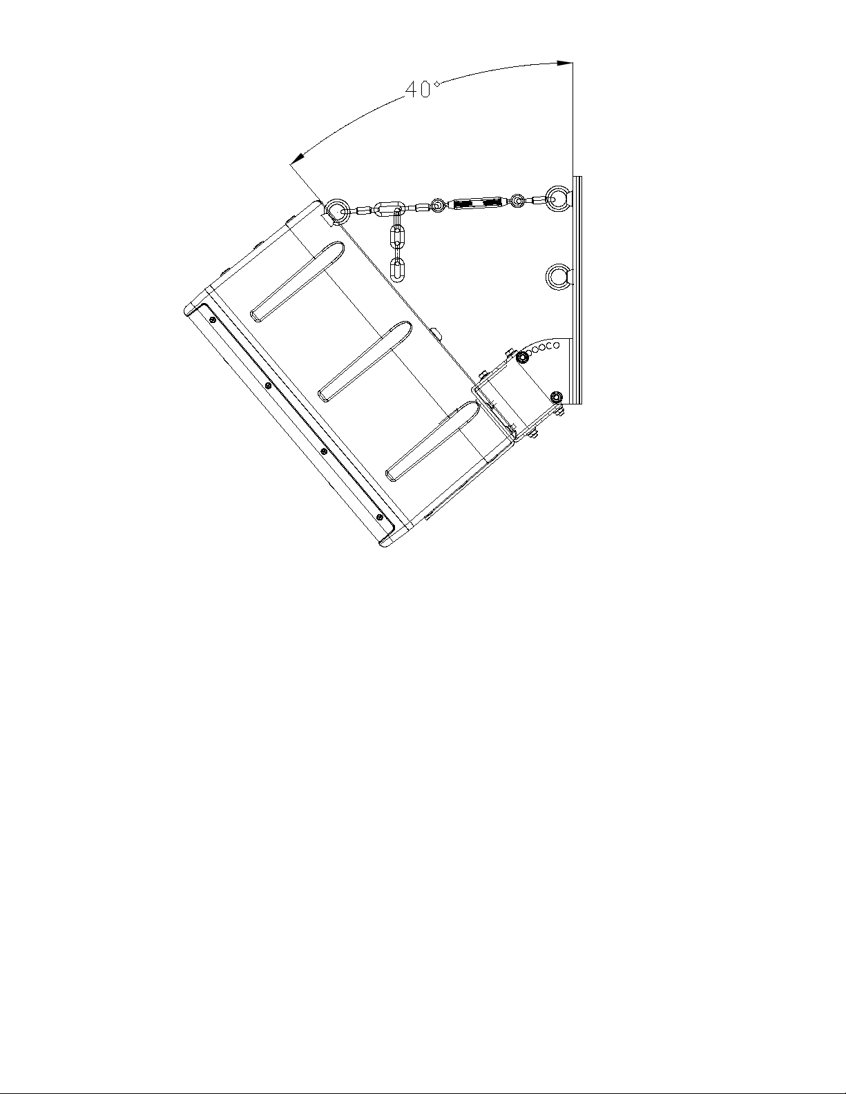
Figure 8c
Figure 8c represents the Link assembly with the enclosure in a 40-degree tilt. The
Link assembly uses the top eyebolt and the stainless steel chain has been added
to achieve the proper tension on the assembly. Notice the “dropped” chain links in
Figure 8c.!
Warning: If the turnbuckle assembly is turned and the loudspeaker
enclosure’s angle begins to change (if the down tilt angle begins to move
toward 0 degrees vertical then the turnbuckle has been OVER-TIGHTENED.
Turn the turnbuckle until the down tilt angle is set by the M10 thru bolt on the
pole bracket but there is still slight tension on the turnbuckle. DO NOT
OVER-TIGHTEN THE TURNBUCKLE! ONLY VERY SLIGHT TENSION IS
REQUIRED!
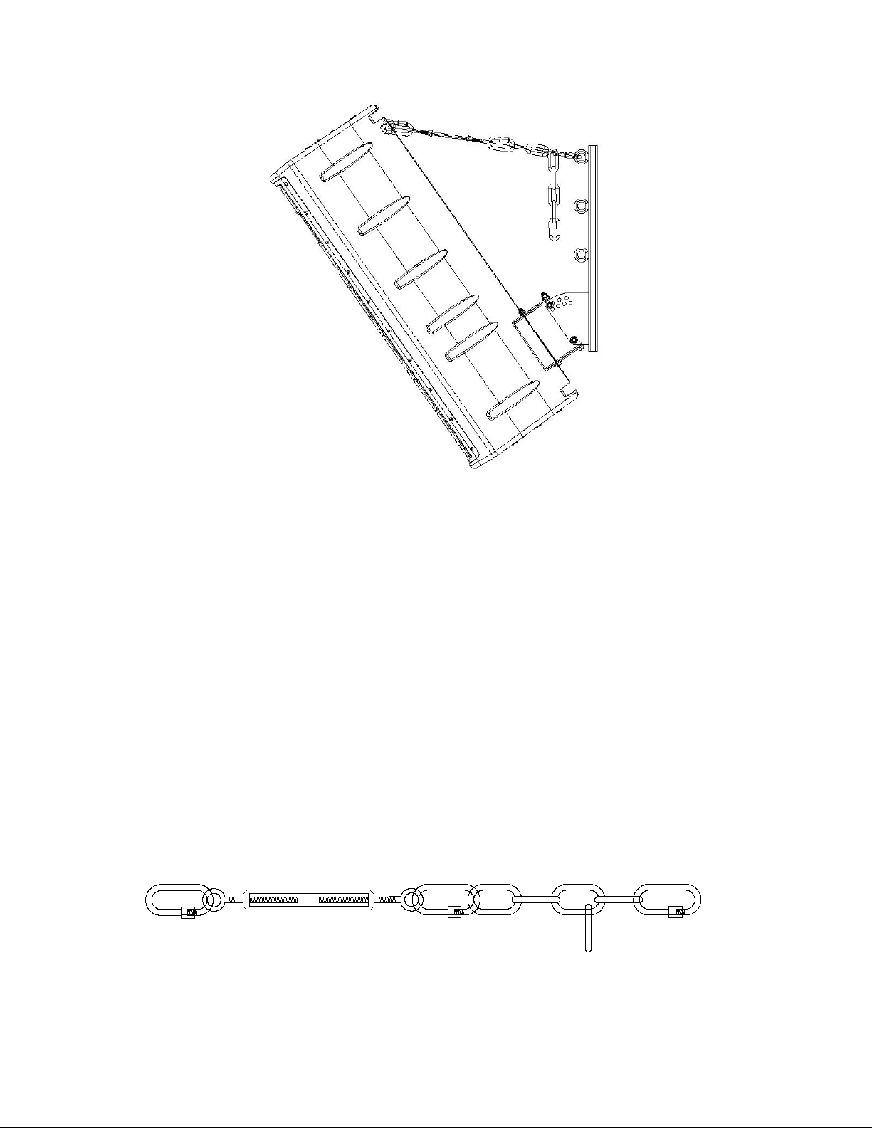
Figure 9 shows a 312.HC mounted to a PT76.M. The down tilt is 35 degrees so
the top eyebolt is utilized as per Figure 7.
9
© 2020 One Systems, Inc, All Rights Reserved
Page 13
13
Figure 9
Figure 9 represents the maximum down tilt angle of 35 degrees from vertical. Note
that because the down tilt angle is 35 degrees, the top eyebolt has been used again
per Figure 7.!
Figure 10 is a close up view of the Link assembly. Certain down tilt angles may
require a link to be “dropped” from the chain as shown below. The lower quick link
is positioned in various chain segments based on the desired degree of down tilt.
The turnbuckle should be adjusted, as described in this section!
In any position, the turnbuckle must be adjusted to allow the proper amount of
tension on the Link. The Link should never pull the loudspeaker up towards
vertical. Only apply VERY slight tension to the turnbuckle! The Link may be
configured with or without the chain section and quick link depending on the down
tilt angle of the enclosure.
13
Figure 9
Figure 10
© 2020 One Systems, Inc, All Rights Reserved
10
Page 14

Secondary safety cables are STRONGLY recommended and should be
secured to a structural point NOT associated with the PT bracket or
loudspeaker. The Link assembly is NOT a secondary safety cable.
APPENDIX 1
(Projected Area Values)
These values were determined by adding the projected areas of the high
frequency horns, the woofer cones and ports to the cross sectional area of the
front of each enclosure listed below. Each enclosure will present a different EPA
based on wind direction. The values listed below are for wind loads directly into
the front of the enclosure and represent maximum values.!
" 108.HTH……………………… 250 in
2
(161,290 mm
2
) (60 x 40 HF horn)!
" 208.HTC……………………… 207 in
2
(133,550 mm
2
)!
" 108.HSB……………………… 250 in2 (161,290 mm2)!
"!
" 108.HTC……………………… 169.4 in2 (109,278 mm2)!
" 108.STC……………………… 169.4i in2 (109,278 mm2)" !
" 112.HTH ……………………… 600 in2 (387,096 mm2) (60 x 40 HF horn)!
" 212.HC………………………… 600 in2 (387,096 mm2)!
" 312.HC………………………… 804 in2 (550,000 mm2)!
" CFA2.HTH…………………….. 855 in2 (552,100 mm2)!
" 118.HSB………………………. 531 in2 (342,516 mm2)
© 2020 One Systems, Inc, All Rights Reserved
11
Page 15
APPENDIX 2
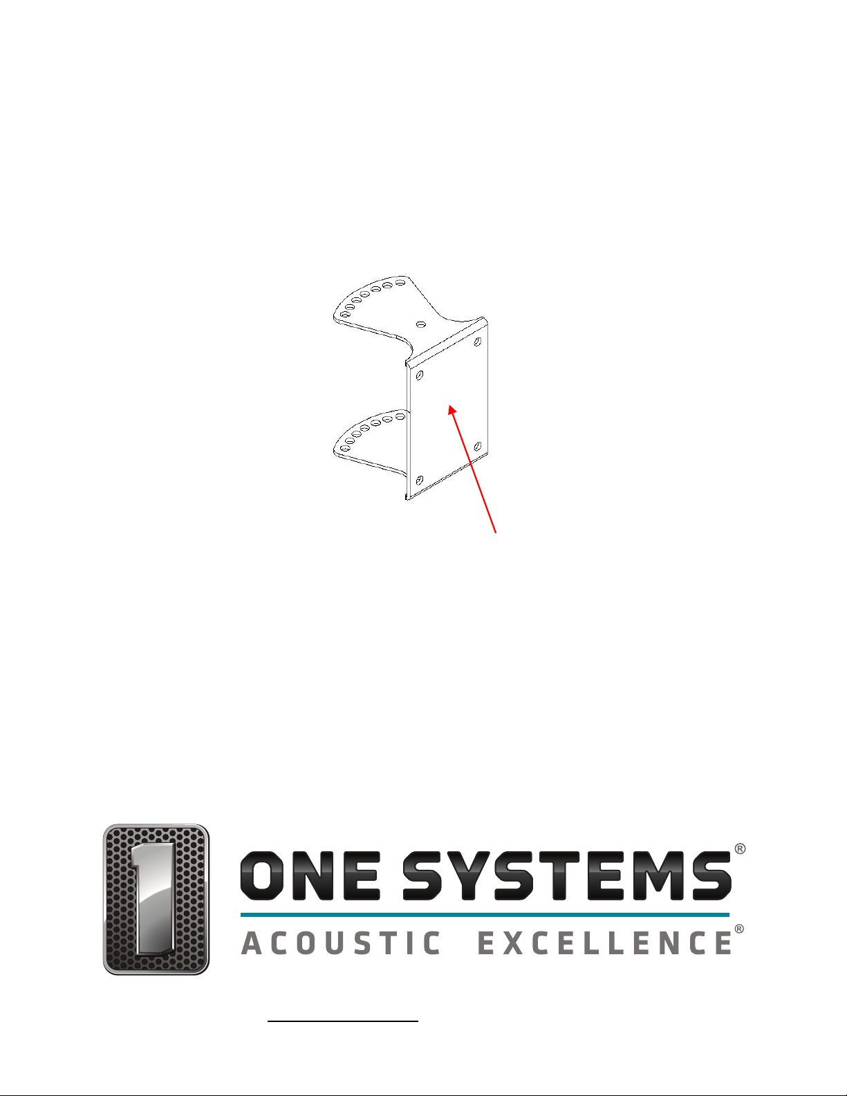
IF the PT76.M is being used with the One Systems 118.HSB, the silicone gasket
(supplied with the 118.HSB) must be placed on the surface of the speaker
mounting bracket BEFORE the speaker mount bracket is attached to the rear of
the 118.HSB. The silicone gasket is placed on the surface as shown below.
The Silicone gasket (supplied with the 118.HSB) is placed on this surface BEFORE
the speaker mounting bracket is attached to the rear of the 118.HSB!
The products referenced in this manual are in conformity with the following
standards or other normative documents: Machinery Directive 2006/42/EC
© 2020 One Systems, Inc,
One Systems, Inc."" www.onesystems.com tel:+1-615-823-1655 fax: +1-615-261-1429
12
 Loading...