

Page 1
PORTABLE OUTDOOR POWERED SYSTEM 15a
POPS15a USER MANUAL
The exclamation point within an equilateral triangle is intended
to alert the user to the presence of important operation and maintenance
instructions.
The lightening flash with arrowhead symbol within an
equilateral triangle is intended to alert the user to the presence of
uninsulated “dangerous voltage” within the product’s enclosure that may
be of sufficient magnitude to constitute a risk of electric shock to persons.
NOTE: The POPS 15a uses an auto-detection circuit that senses and
adjusts internal operating voltages to the AC Mains supply. The POPS 15a
will operate between 104VAC and 253VAC.
Although the AC Mains is automatically selected the user must insure that
the proper AC Mains cable is supplied (GFCI enabled for 115VAC operation
and PRCD enabled for 230VAC operation)
Page 2

The Portable Outdoor Powered System 15a (POPS15a) was designed by One
Systems to fulfill a unique need in the professional audio marketplace. The
POPS15a was designed for use in any direct-weather outdoor applications, such
as sporting events, theme park events, civic celebrations and general outdoor
presentations. The POPS15a was designed for ALL weather applications and all
its components were developed for use in rain, snow and other inclement
weather applications. The highly-portable design is also ideal for mobile
applications in gymnasiums, indoor and outdoor swimming pools and meeting
rooms. The unique “narrow profile” integrated woofer and enclosure design
provide superior acoustic output with excellent sight-line characteristics.
Specifications
Frequency Response: 50 Hz – 18,000 Hz
Coverage Pattern: 60o H X 40o V
Input / Thru: 3-Pin XLR-type (IP 67)
(Pin 2 +)
Power
Peak - Total System: 2,000 Watts
Continuous- Total System: 1,000 Watts
Peak Low Frequency: 1,000 Watts
Peak High Frequency: 1,000 Watts
Continuous Low Frequency: 500 Watts
Continuous High Frequency: 500 Watts
AC Mains Power: 104 VAC – 253 VAC
(50 Hz – 60 Hz)
Max Acoustic Output (Peak): 130 dB*
Page 3
Weather Performance: IEC 529 / IP 56
Rigging: M10 Stainless Steel (7 Points)
Supplied Accessories: AC Mains Cable (100 Ft - 30.5 m)
Input / Output XLR-XLR (100 Ft - 30.5 m)
(Both Cables Supplied on Cable Reels)
Dimensions (H X W X D): 742 X 370 X 434 mm
29.2 X 14.6 X 17.1 inches
Weight 29 kg (64 lbs)
Operating temperature 0C – 40C (32F – 104F)
Available Accessories POPS Sub a
M10 eyebolt kit
* NOTE: Actual measured response using a calibrated SPL meter with peak
responding meter. Stimulus was a 1/3 octave band of pink noise with a 1 second
duration.
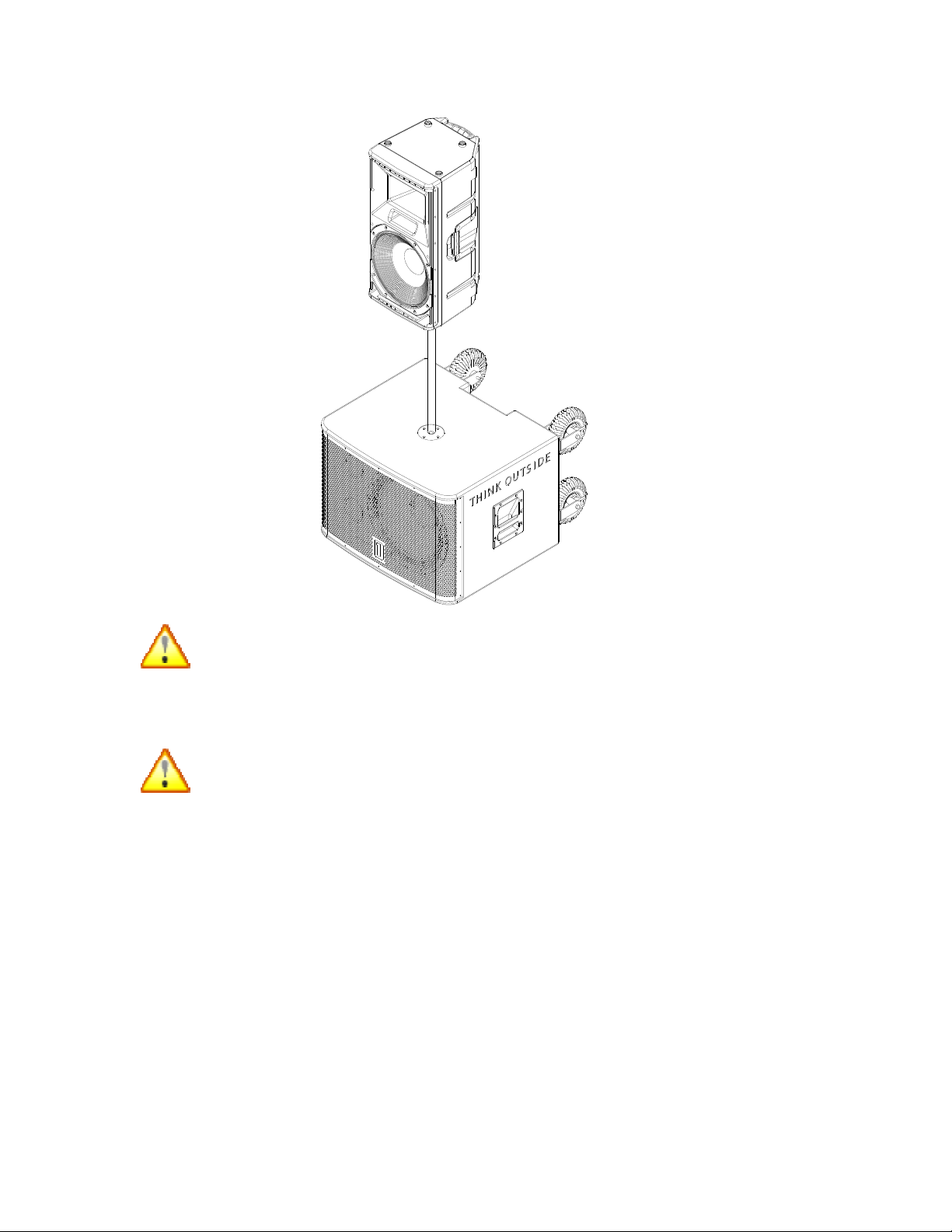
The image below shows POPS15a mounted on POPSSub a using the pole
supplied with the POPSSub a.
Page 4
Read all of the instructions included in this manual
NOTE: The AC mains supply end of the POPS15a power cable MUST be
plugged into a supply source that has a GROUND FAULT CIRCUIT
INTERRUPTER (GFCI). The 115 V version is supplied with an in-line GFCI. The
230 Vac version is supplied with a Portable Residual Current Device (PRCD). In
Europe, these devices are also referred to as Residual Current Devices or
Residual Current Circuit Breakers.
NOTE: THE RESET ON THIS DEVICE SHOULD BE TESTED TO VERIFY
PROPER OPERATION OF THE SAFETY DEVICE!
POPS15a is supplied with an “in line” GFCI device for use in countries that use
115VAC. DO NOT bypass this device or disable. The end of the AC Mains cable
that is plugged in to the AC Mains supply must be in a dry condition.
Page 5

POPS15a is supplied with an “in line” PRCD device for use in countries that use
230VAC. DO NOT bypass this device or disable. The end of the AC Mains cable
that is plugged in to the AC Mains supply must be in a dry condition.
NOTE: If a hard-wired GFCI or PRCD device is already located at the AC Mains
source connection then the “in line” devices may be removed. THIS MUST BE
DONE BY A LICSENSED ELECTRICIAN THAT IS FAMILIAR WITH ALL LOCAL
AND NATIONAL ELECTRICAL CODES AND PRACTICES.
DO NOT BYPASS THE GFCI OR PRCD DEVICE UNLESS YOU ARE FULLY
LICSENSED AND QUALIFIED TO DO SO!
Copies of this manual should be retained by both the system installer AND end
user.
This manual must be read and understood and ALL warnings must be followed.
Follow all instructions to insure optimal product performance.
POPS15a’s amplifier is a convection-cooled device and requires at least 7 inches
(178 mm) of clearance behind the enclosure to allow the heat sink to adequately
cool the internal electronics.
SEE SECTION BELOW ON THE POPS15a AND HIGH TEMPERATURE,
AMBIENT ENVIRONMENTS AND SOLAR GAIN.
DO NOT INSTALL NEAR ANY HEAT SOURCES!
Use ONLY the supplied AC Mains connector. DO NOT SUBSTITUTE!
Protect the AC Mains power cord from being walked on or otherwise damaged
and inspect for damaged connections and damaged insulation.
THE AC MAINS CONNECTION WHERE THE AC MAINS CABLE IS
CONNECTED TO THE AC MAINS LINE MUST BE LOCATED IN A DRY
LOCATION!
Use ONLY the supplied XLR/XLR cable. DO NOT SUBSTITUTE!
POPS15a may be suspended. DO NOT SUSPEND ANY ITEMS OR OTHER
ENCLOSURES BELOW THE POPS15a.
DO NOT SUBSTITUTE SUSPENSION HARDWARE.
SUSPENSION SHOULD BE DONE BY SOMEONE FAMILIAR WITH LOCAL
AND NATIONAL CODES AND SAFE SUSPENSION PRACTICES
Page 6

WARRANTY
ONE SYSTEMS products are warranted by ONE SYSTEMS, INC. or ONE
SYSTEMS Global Co. Ltd for a period of 5 years (3 years for all electronic
products). This warranty period begins with the date of purchase by the original
end-user of the product. All products are warranted against defects in materials
and workmanship.
This Limited Warranty does not cover product abuse including, but not limited to,
mechanical and thermal failures associated with excessive input power applied to
ONE SYSTEMS loudspeaker systems. In addition, damage caused by accident,
misuse or failure to observe instructions included in the following manuals:
“Outdoor installation of loudspeakers” and “Rigging and Suspension of ONE
SYSTEMS products” (These manuals may be found on the ONE SYSTEMS web
site, www.ONESYSTEMS.com) is not covered. Other acts which are not the fault
of ONE SYSTEMS are not covered. Defects or damages resulting from service,
testing, product modification or alteration by someone other than ONE
SYSTEMS or its authorized agents or service centers are not covered. ONE
SYSTEMS is not responsible for misrepresentations by the seller or other parties.
All products covered by this limited warranty must be shipped to an authorized
service center (see details below) prepaid. ONE SYSTEMS will pay all material
and labor costs associated with repair or replacement of covered products. ONE
SYSTEMS will pay all return costs associated with products covered under the
terms of this limited warranty.
Limitation of Implied Warranties
ANY IMPLIED WARRANTIES, INCLUDING WITHOUT LIMITATION THE
IMPLIED WARRANTIES OF MERCHANTABILITY AND FITNESS FOR A
PARTICULAR PURPOSE, SHALL BE LIMITED TO THE DURATION OF THIS
LIMITED WARRANTY, OTHERWISE THE REPAIR, REPLACEMENT, OR
REFUND AS PROVIDED UNDER THEIS EXPRESS LIMITED WARRANTY IS
THE EXCLUSIVE REMEDY OF THE END USER (CONSUMER), AND IS
PROVIDED IN LIEU OF ALL OTHER WARRANTIES, EXPRESS OF IMPLIED.
IN NO EVENT SHALL ONE SYSTEMS , OR ANY OF ITS OPERATING
DIVISIONS, BE LIABLE, WHETHER IN CONTRACT OR TORT (INCLUDING
NEGLIGENCE) FOR DAMAGES IN EXCESS OF THE PURCHASE PRICE OF
THE PRODUCT, ACCESSORY OR SOFTWARE, OR FOR ANY INDIRECT,
INCIDENTAL, SPECIAL OR CONSEQUENTIAL DAMANGES OF ANY KIND,
OR LOSS OF REVENUE OR PROFITS, LOSS OF BUSINESS, LOSS OF
INFORMATION OR DATA, SOFTWARE OR APPLICATIONS OR OTHER
FINANCIAL LOSS ARISING OUT OF OR IN CONNECTION WITH THE ABILITY
OR INABILITY TO USE THE PRODUCTS, ACCESSORIES OR SOFTWARE TO
THE FULL EXTENT THESE DAMAGES MAY BE DISCLAIMED BY LAW.
Page 7
Some states and jurisdictions do not allow the limitation or exclusion of
incidental or consequential damages, or limitation on the length of an
implied warranty, so the above limitations or exclusions my not apply. This
warranty provides specific legal rights, and other rights may exist from
state to state or from one jurisdiction to another
REGULATORY AND SAFETY DATA
This product was tested to International Standards for safe operation. POPS15a
is compliant with EN60065. Test certification may be obtained from One
Systems.
CONTENTS
POPS15a system contains three cartons. The contents of the cartons are as
follows:
POPS15a ENCLOSURE
One Portable Outdoor Powered System 15a (POPS15a) that includes a BiAmplified class D digital power amplifier system with on-board Digital Signal
Processing (DSP).
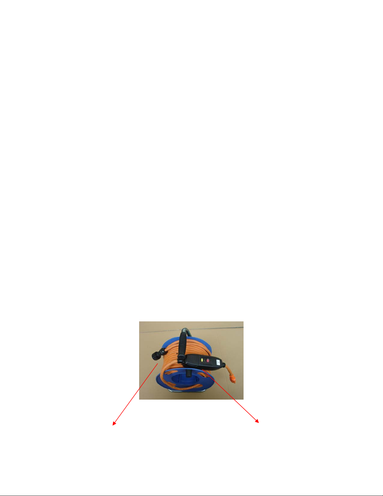
AC MAINS CABLE REEL
100 ft. (30.5 m) of SJOW-rated AC mains cable with an IP 68-rated cable end
connector designed to mate to the connector on POPS15a’s enclosure. The
cable is supplied on a portable cable reel. This cable assembly consists of a
moisture-resistant connector designed to be plugged into POPS15a.
The other end of this cable assembly consists of either a GFCI (Ground Fault
Circuit Interrupter) and the appropriate mating plug for 115 V AC Mains voltage
or a Portable Residual Current Device (PRCD) for 230 V AC Mains voltage.
NOTE: THIS CABLE END MUST BE IN A DRY LOCATION!
Showing GFCI device DRY LOCATION)
POPS15a cable end AC Mains End (MUST BE USED IN
Page 8

INPUT/OUTPUT CABLE
100 FT. (30.5 M) of SJOW-rated two-conductor shielded input/output cable with
an IP 67 rating. The cable is supplied on a portable cable reel.
RECOMMENDED ACCESSORIES
Although not supplied with the POPS15a, One Systems recommends using
POPS15a enclosures with a high-quality loudspeaker stand. One Systems
recommends using a stand with a “crank up” feature to allow easy vertical
adjustments. On Stage Stands model SS8800B+ or equivalent is recommended.
(On Stage Stands may be contacted at 1-800-289-8889 to determine the dealer
closest to your location).
One Systems also highly recommends the POPSSub a. This active subwoofer is
an ideal match for the POPS15a. POPSSub a and POPS15a are shown below:
NOTE: The POPSSub a is supplied with a pole designed to mount the POPS15a
to the POPSSub a. DO NOT SUBSTITUTE OTHER POLES AND MOUNT ONLY
THE POPS15a ON TOP OF THE POPSSub a!
Page 9

OTHER ACCESSORIES
One Systems also offers an M10 eyebolt kit that consists of 4 pieces of a 304grade stainless steel eyebolt for use with POPS15a. This eye bolt kit is designed
for temporary suspension of POPS15a.
FEATURES AND APPLICATIONS
POPS15a is a very unique product and may be used in “wet” outdoor
environments. The AC Mains and input/output connectors are designed to
provide a high degree of ingress protection. All mechanical connections are rated
IP 67 or higher. POPS15a may be safely installed in outdoor environments as
long as ONLY the supplied cables are utilized. DO NOT SUBSTITUTE CABLES.
POPS15a is a professional product and is designed to be used with a highquality mixing console. POPS15a does not provide any additional, userselectable, equalization or gain. Both equalization and gain functions should be
provided by the mixing console.
One Systems does not feel that adding additional EQ and gain functions are
appropriate for truly professional products. The addition of redundant functions
Page 10

such as EQ and gain are usually the cause of clipping and distortion. These
functions are easily provided by either an outboard mixing console or outboard
EQ devices.
POPS15a features an onboard digital signal processor (DSP) that performs
analog to digital conversion, equalization, high-order crossover, delay and
system dynamics processing.
POPS AND HIGH AMBIENT TEMPERATURES
POPS15a has been designed to work in a wide range of ambient temperatures.
When using POPS15a however, consideration must be given to both the ambient
temperature and the added heat produced by exposure to direct sunlight.
In a “shaded” environment, POPS15a is rated for normal operation up to 40o C
(104o F). In environments where POPS15a is subjected to direct sunlight, a
portion of that direct solar energy is absorbed by the enclosure and the external
heat sink. POPS15a’s color and resin formulations have been specifically
designed to minimize the thermal/solar gain of the enclosure and the heat sink
has been clear- anodized to minimize its solar gain as well.
It is recommended that whenever possible POPS15a should be used in either a
shaded area, or shade provided via an external “umbrella” type of sun shade.
Solar gain precautions should be taken any time the ambient (air) temperature is
90 F (32 C) or higher and if POPS15a is intended to be used in direct sunlight.
SETUP AND USE OF POPS15a
All connections to POPS15a are made on the rear amplifier panel. The input
panel is shown below:
ON/Off Switch
Page 11

AC MAINS CONNECTION
Prior to connecting the AC mains cable, insure that the AC mains switch on the
POPS15a is in the OFF position.
NOTE: If the POPS 15a is being used with the POPS Sub a, the best practice is
to turn on the POPS 15a PRIOR to turning on the POPS Sub a. During the turn
off sequence, either the POPS 15a or the POPS Sub a may be turned off first!
NOTE: DO NOT CONNECT THE AC MAINS CABLE TO POPS15a IF WATER
OR MOISTURE IS PRESENT IN EITHER END OF THE CONNECTOR!
POPS15a MUST be connected to the correct AC Mains voltage! There are two
(2) versions of the POPS15a, both use the same enclosure but different AC
Mains cables:115 VAC or 230 VAC. You MUST insure that you have the correct
AC Mains cable version that matches your AC Mains voltage! The required AC
mains frequency is between 50 Hz and 60 Hz.
POPS15a uses a waterproof AC mains connector system. To mate the AC mains
cable with the AC mains connector on the amplifier’s input plate, align the cable
end with the amplifier panel’s connector and push with sufficient force until you
hear a “click” sound that indicates the cable and chassis connector are properly
mated. Support the POPS15a’s enclosure with one hand while performing this
operation. The AC mains connector is shown below. It is located on the lower
portion of the POPS15a’s input panel.
INSURE THAT THE AC MAINS CABLE IS SECURLY CONNECTED AND
“LOCKED” INTO POSTION. DO NOT USE POPS15a IF THE AC MAINS
CONNECTOR IS NOT SECURELY-MATED TO THE AMPLIFIER MODULE!
Page 12

AC Mains panel connector
NOTE: ALWAYS turn off the AC mains power BEFORE attempting to disconnect
the AC mains cable from POPS15a’s amplifier module!
To disconnect the cable end of the AC mains connector pull back on the collar of
the cable end connector in the direction shown on the connector. While pulling
back on the collar pull the cable end connector away from the chassis connector.
It is necessary to physically support the enclosure while disconnecting the AC
Mains connector to avoid pulling the enclosure over if the enclosure is not
securely mounted.
The AC mains supply end of the cable is shown in the image below (Image 1)
Once the AC mains cable is connected to POPS15a’s amplifier, the other end of
the AC mains cable may be connected to the AC mains supply. This end of the
AC mains cable is a standard connector and MUST be connected in an area that
is DRY. The figure below shows both ends of the AC mains cable. The connector
on the right side of this photo is the IP 68-rated cable end that should be
connected to the AC mains input on POPS15a’s amplifier module. The connector
on the left side of this photo is connected to the AC mains supply located in a dry
area.
NOTE: The configuration of the connector on the left side will vary depending on
which region of the world POPS15a is used in.
Page 13

AC mains cable ends (Image 1)
AC Mains supply end (115 V AC version shown)
DO NOT CONNECT THE AC MAINS END OF THE AC MAINS CABLE IN AN
AREA THAT IS WET OR SUBJECT TO CONDENSATION OR DAMP
CONDITIONS!
The AC Mains end of the cable assembly uses an “in line” GFCI device (115 V
AC) or a PRCD device (230 V AC). DO NOT disconnect this device!
NOTE: The AC Mains cable is an extension cable. It is a high-quality cable with
low line loss. Connecting the AC Mains cable to another extension cable will
produce additional line loss and can result in low ac mains voltage at the POPS
amplifier module. It is not recommended that additional extension cables be
used with this AC Mains connector.
Once the AC mains cable is securely connected to the amplifier and AC mains
supply, POPS15a may be powered up. A good practice is to make sure the audio
levels on the mixer’s output (or other source output) are reduced or muted prior
to applying power to POPS15a.
NOTE: When power is applied to POPS15a and the unit is turned on there is a
short delay before the pilot light illuminates.
Page 14

Signal Present Pilot Light
NOTE: If the pilot light does not illuminate within 30 seconds, the unit may be in a
FAULT CONDITION. The unit should be returned to One Systems for evaluation.
THERE ARE NO USER-SERVICABLE PARTS INSIDE. DO NOT REMOVE THE
AMPLIFIER MODULE!
AUDIO CONNECTIONS
POPS15a includes two male XLR connectors. This configuration differs from the
standard male input and female out/thru due the to water and moisture
requirements of the product. Both the input and output/thru XLR connectors on
the POPS15a are made by Neutrik and require use of Neutrik connectors
NC3FXX-HD-D. The supplied XLR to XLR audio cable has two of the NC3FXXHD-D connectors.
The image below illustrates the top portion of the POPS15a input plate. Both the
audio input and audio thru connectors are shown. In this image both connectors
are shown with their water covers in place.
POPS15a also includes a “signal present” indicator and is positioned immediately
below the Pilot light. This indicator will illuminate when an audio signal is present
at the input to the system. The threshold is approximately -25dBV.
Page 15

When the audio connectors are not in use the water covers should be inserted in
the XLR connector. (Example: If the audio input is being used but the audio thru
connector is not being used the water cover should be inserted in the audio thru
XLR)
The image above shows both the INPUT and THRU connections with their water
covers in place.
Connect the audio out from the console/mixer using the supplied XLR to XLR
cable.
POPS15a also features an audio output/thru. This connection MUST also use a
Neutrik NC3FXX-HD-D cable end connector. The picture below shows the water
cover removed from the image for clarity. The water covers are permanently
attached to POPS15a’s input plate and will hang down from the panel when not
inserted in the audio input or audio thru XLR connectors.
Input
Page 16

NOTE: Care must be exercised to insure that each end of the XLR connector is
securely seated into the mating panel connector and gets locked into place.
Insert the connector into the panel’s connector until a soft “click” is heard. This
indicates the cable end is properly retained in the panel connector. To remove
the XLR connector, simply squeeze the rubber “boot” of the connector on the top
and bottom as near to the panel end of the boot as possible.
Failure to properly seat and secure the connector will significantly reduce the
water protection features designed into the connector’s assembly.
DO NOT USE THE CONNECTOR IF MOISTURE IS PRESENT IN THE PANEL
CUTOUT OF THE XLR CONNECTOR. THE PANEL’S CONNECTOR MUST BE
DRIED PRIOR TO CONNECTION!
POPS15a’s input section also allows for “paralleling” multiple POPS15a systems.
This function is achieved by using the output/thru XLR connector located next to
the input XLR connector on POPS15a’s amplifier module. This input is shown
below.
Input Thru
NOTE: Neutrik NC3FXX-HD-D connectors MUST be used for ALL audio
connections on POPS15a!
Page 17

WARNING: DO NOT SUBSTITUTE “NORMAL” XLR CABLE CONNECTORS.
FAILURE TO USE NEUTRIK NC3FXX-HD-D CONNECTORS WILL
COMPROMISE THE WATER / MOISTURE RATING OF POPS15a AND MAY
RESULT IN UNSAFE CONDITIONS. NEUTRIK NC3FXX-HD-D CONNECTORS
MUST BE USED FOR ALL CONNECTIONS ON POPS15a.
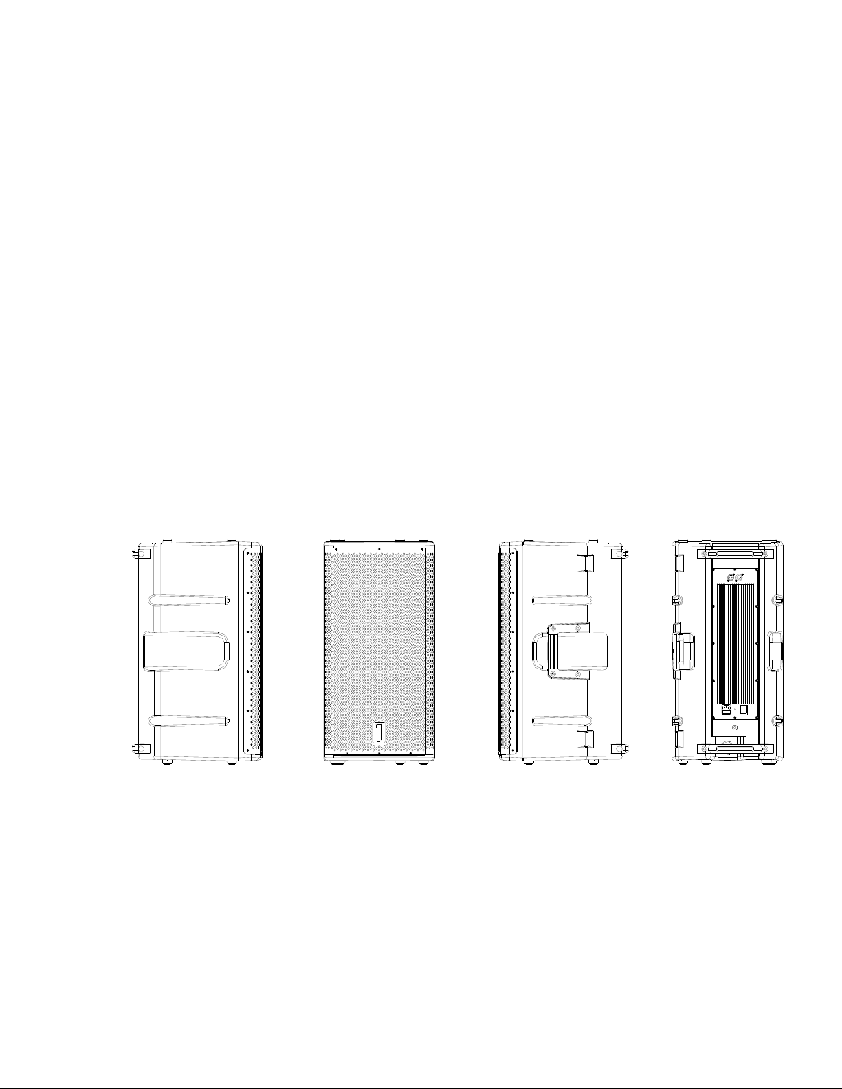
RIGGING AND SUSPENSION OF POPS15a
POPS15a features 7 x M10 (metric) stainless steel rigging points. The enclosure
may be suspended for temporary installations. There are four M10 points on the
top of the enclosure, two on the bottom of the enclosure and a single “pull up”
point on the rear, bottom portion of the enclosure.
WARNING: The single M10 point on the rear of the enclosure is NOT intended
for suspension of the enclosure and should NOT be used for suspension. The
M10 point on the rear of the enclosure is for pull up and aiming ONLY!
The M10 rigging points are shown in the image below.
Rigging Points Shown Above
DO NOT USE THE BACK POINT FOR SUSPENSION
THIS POINT IS FOR “PULL UP” ONLY!
Page 18

POPS15a may be mounted to any high-quality loudspeaker stand with a
standard 1.375 inch (35 mm) diameter mounting pole. The mounting pole MUST
be located on a level surface that is capable of safely supporting the weight of
both the loudspeaker stand and the POPS15a. It is necessary to verify safe
operation with the loudspeaker stand supplier/manufacturer.
DO NOT ADD OR SUSPEND ANY ITEMS TO THE POPS15a OR
LOUDSPEAKER’S STAND
WARNING
DO NOT ATTEMPT TO SUSPEND ONE SYSTEMS PRODUCTS WITHOUT
UNDERSTANDING LOCAL AND NATIONAL CODES THAT APPLY TO
OVERHEAD SUSPENSION OF PRODUCTS.
DO NOT ATTEMPT TO SUSPEND ONE SYSTEMS PRODUCTS UNLESS YOU
ARE A PROFESSIONAL WITH KNOWLEDGE OF LOCAL AND NATIONAL
CODES RELATED TO SAFE SUSPENSION AND ARE EXPERIENCED IN
SUSPENDING PRODUCTS OVERHEAD.
ONE SYSTEMS IS NOT RESPONSIBLE FOR FAILURES RELATED TO NONCOMPLIANCE WITH LOCAL AND NATIONAL CODES AND SAFE
SUSPENSION PRACTICE.
DO NOT ATTEMPT TO SUSPEND THIS PRODUCT WITHOUT READING AND
UNDERSTANDING THE DOCUMENT “ Rigging and Suspension of ONE
SYSTEMS Products”. THIS DOCUMENT MAY BE FOUND AT:
www.onesystems.com. In the “Education” section of the One Systems website.
ALL ASSOCIATED RIGGING IS THE RESPONSIBILITY OF OTHERS.
USING POPS15a (Application and Trouble-Shooting Tips)
POPS15a is a high-quality professional sound reinforcement system designed for
use in both direct weather outdoor applications as well as high ambient noise
indoor applications. Some basic precautions will insure long-term reliability.
Page 19

Although POPS15a is designed for direct weather applications insure that no part
of the front of the enclosure is directed upward beyond vertical. The highfrequency section of POPS15a is horn-loaded and water can collect in the horn’s
throat and driver if the horn is tilted upward.
EQUALIZATION AND GAIN
POPS15a has all the required equalization and gain functions included in its
internal Digital Signal Processor (DSP). Both the equalization and gain functions
have been optimized for flat frequency response and maximized system
dynamics. POPS15a does not have user-settable external gain or EQ.
All system gain should be set via the outboard mixing console. The mixing
console should be capable of providing sufficient output signal levels to supply
the necessary voltage levels to drive POPS15a to full power and still insure
adequate headroom in the mixing console. The mixing console needs to be
capable of driving 100 feet (30.5 m) of balanced cable as well as the POPS15a.
NOTE: When both POPS15a and POPSSub a are used as a system, care
should be exercised since the POPSSub a does feature an external, useradjustable, gain control to select the desired levels of bass and sub-bass output
relative to the POPS15a’s full-range output.
If additional equalization is required, care should be taken to avoid excessive EQ
in any band, but particularly at low frequencies. Excessive equalization can
produce “band selective” clipping and distortion. All EQ boost levels should be
monitored if system distortion is present.
Applications that require excessive low frequency equalization are almost always
an indication that a subwoofer is required. One Systems offers the POPSSub a.
POPSSub a is a companion product designed for use with POPS15a and will
provide substantial low frequency acoustic output.
DISTORTED SOUND
When desired levels exceed POPS15a’s gain structure limitations, the internal
dynamics processing functions will engage and provide system protection.
However, it is still possible to “overdrive” the input section of the system or to
overdrive, or clip the output stages of the source electronics. If distorted sound is
present the following steps should be taken:
1. Verify that the mixer’s output is not clipping or overloaded. If the output
metering section of the mixing console is continuously in the “red” then the
Page 20

output level should be reduced. (Occasional “red” indications are usually
fine, depending on the mixing console’s output capability).
1. Also verify that any other electronic devices in the signal chain are not
being overdriven.
2. Verify that excessive equalization is not present anywhere in the signal
chain.
3. Verify that AC mains levels are within the required range.
Voltage measurements on the AC Mains should be performed by a licensed
electrician or individual trained in making high voltage measurements.
NO SOUND
1. Verify that signal is present on the input of POPS15a. If the signal present
light is illuminated and there is still no output please contact your One
Systems dealer or One Systems directly.
2. Verify that there is AC Mains voltage on POPS15a’s AC Mains input
3. If AC Mains voltage is present, verify that POPS15a’s fuse is not blown. If
POPS15a’s fuse is blown you MUST replace it with the type noted on the
panel directly above the fuse holder!
NOTE: IF THE FUSE IS BLOWN, REPLACE ONLY WITH THE SAME TYPE OF
FUSE. THIS FUSE TYPE IS NOTED ON THE SPEAKER’S INPUT PANEL
NEAR THE FUSE HOLDER. THE LOCATION OF THE FUSE HOLDER IS
SHOWN BELOW.
Fuse Holder
Page 21

The fuse holder is a waterproof design. Insure that its gasket is properly seated
when replacing the fuse. Insure that the fuse holder’s cover is securely tightened.
DO NOT OVERTIGHTEN THE FUSE HOLDER COVER.
PRODUCT SERVICE
There are NO user-serviceable parts inside POPS15a (see “Replacement of
Components” section below for clarification and exceptions to this statement).
POPS15a’s amplifier module MUST be serviced by an individual authorized by
One Systems.
POPS15a’s amplifier is attached to the enclosure using 12 x M4 stainless steel
machine screws with special “sealing washers”. The unique self-sealing feature
of these washers forms a waterproof seal between the amplifier module and the
enclosure.
The washers are supplied by Gaynor Industries and are Gaynor Industries part
number LTN37164
DO NOT SUBSTITUTE WASHER TYPES.
Replacement of Components
DO NOT ATTEMPT ANY REPAIRS UNLESS POPS15a’s AMPLIFIER HAS
BEEN DISCONNECTED FROM THE AC MAINS SOURCE!
REPLACEMENT OF COMPONENTS MUST BE PERFORMED BY A
QUALIFIED TECHNICIAN OR ONE KNOWLEDGABLE IN THE REPLACEMENT
OF TRANSDUCER COMPONENTS!
In the event of woofer failure, the woofer may be accessed by removing the front
grille and then removing the woofer. This should be done by a qualified
technician or contractor. There is no need to remove the amplifier’s panel in the
event of a woofer failure. Insure that proper wiring polarity is observed. Note the
wiring polarity before disconnecting the woofer and observe this polarity when
replacing it.
Page 22

In the event of a compression driver failure, the amplifier module must be
removed to gain access to the compression driver. Remove the 12 stainless steel
screws located around the perimeter of the amplifier module.
USE EXTREME CARE WHEN HANDLING POPS15a’s AMPLIFIER MODULE.
THE COMPONENTS ON IT ARE FRAGILE AND THE MODULE MUST NOT BE
SET DOWN ON THE COMPONENT SIDE OR DAMAGE WILL OCCUR!
Care should be exercised when disconnecting the amplifier module from the
woofer and the compression driver. Be sure to observe the wiring polarity of both
the woofer and the compression driver.
NOTE: The wires for the compression driver may be disconnected from the
POPS15a’s amplifier by simply removing the Phoenix connector with the orange
and yellow wires from the terminal block on the amplifier module. Before
removing, insure that these are the wires running to the compression driver.
The compression driver is a “screw on” type and is easily removed once the
amplifier module has been removed. Once the compression driver’s diaphragm
has been replaced and re-mounted on the horn, the amplifier may be remounted.
Insure that both the woofer and compression driver are connected with the
correct polarity.
Use the same stainless steel screws and LTN37164 washers to mount the
amplifier’s module to the enclosure. Insure that no wires are located between the
amplifier module and the enclosure when re-mounting the amplifier module.
© One Systems, Inc. 2012 www.onesystems.com
 Loading...