

Page 1
PM2.M POLE MOUNT BRACKET
INSTALLATION GUIDE V1.00
The PM2.M is an easy to install and flexible system designed to allow One Systems
loudspeaker models to be mounted to pole structures. The only products approved for use with
the PM2.M are the 104.HTH, 106.HTH, 104.STH and 106.STH. !
NO OTHER LOUDSPEAKERS SHOULD BE SUBSTITUTED!
WARNINGS!
The following actions MUST be performed PRIOR to beginning the installation of the PM2.M:!
"!
1. This installation guide must be completely read and understood!!
2. The installation manual “Rigging and Suspension of One Systems Products” must be
read and understood. This guide can be found at www.onesystems.com.!
3. The manufacturer of the pole MUST be consulted to verify the applicability and
acceptability of the PM2.M and the attached One Systems speaker to the specific pole. !
4. The PM2.M pole mount bracket should only be installed by someone experienced in the
overhead suspension of items. They should be familiar with applicable local / national codes
One Systems, Inc © 2020, All Rights Reserved
Page 2

WARNINGS! (cont’d)
governing the installation of these types of products and those governing the attachment of these
types of products to specific pole structures.!
5. The PM2.M is constructed of 316-grade stainless steel. !
NOTE: Caution should be exercised when connecting One Systems Marine-Grade speakers
and Marine-Grade rigging to other dissimilar metals. The potential for galvanic corrosion is
high in marine environments, where the One Systems Marine-Grade enclosures and rigging are
specified or required. Compatible metals and appropriate anode to cathode area ratios must
be maintained. A structural engineer with galvanic corrosion experience should be consulted
prior to installation of ANY One Systems products in marine environments.
CAUTION: All structures outdoors are subjected to wind forces. These forces must be considered
when suspending any product outdoors. It is necessary to know the “Effective Projected
Area” (EPA) of the loudspeaker prior to installation of the loudspeaker and the PM2.M. The
effective areas are shown in Appendix 1. Periodic inspections of the rigging, loudspeaker
enclosure and installation are strongly recommended.!
IMPORTANT NOTE: All products in direct weather installations can be subjected to high wind
speeds. The working load limit and safety factor ratings are provided for static vertical
(gravitational) loads only. For use in high wind areas, One Systems recommends consultation
with a licensed structural engineer to calculate an appropriately re-rated safety factor. For wind
speed exposure over 74 miles per hour (119.1 kilometers per hour, 64.3 knots) the loudspeaker
enclosure, bracket, banding and link assembly or secondary safety must be inspected for
signs of damage or fatigue!
INSTALLATION
The PM2.M consists of two parts: the pole bracket assembly, and the forged shoulder eye bolts
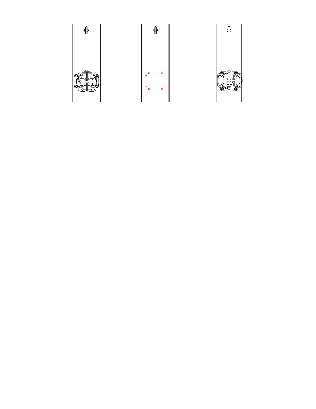
and supplied cable assembly. The pole bracket is shown in Figure 1. The bracket shown in Figure
1 is designed for use on circular poles with diameters of 4 inches (101.6 mm) or larger AT
MOUNTING HEIGHT. The PM2.M may also be used on square or rectangular pole faces of 3.75
inches (92 mm) AT MOUNTING HEIGHT. Round pole diameters that are smaller than 4 inches or
square / rectangular face widths of less than 3.75 inches must not be used.
One Systems, Inc."" www.onesystems.com tel:+1-615-823-1655 fax: +1-615-261-1429
One Systems, Inc © 2020, All Rights Reserved
Page 3
INSTALLATION
Figure 1
NOTE: The PT10.M pan and tilt bracket may be oriented in two ways on the PM2.M’s back
plate. The orientation on the left is used with the 106.HTH or 106.STH is to be mounted. Using
this configuration will result in the 106.HTH or 106.STH being oriented in a vertical orientation.
The PT10.M is mounted using 4 black holes shown the center image above. The red holes,
also shown in the center image, should be used when a 104.HTH or 104.STH is mounted and
the desired orientation of the enclosure is vertical. The PT10.M should be mounted to the
stainless steel back plate before the back plate is mounted to a pole.
1. NOTE: It is best to preset the desired pan and tilt angles PRIOR to mounting the PM2.M
on a pole (see Step 2 below for more details).!
Use ONLY the supplied nuts and bolts to mount the PT10.M to the PM2.M back plate.
DO NOT substitute any parts!!
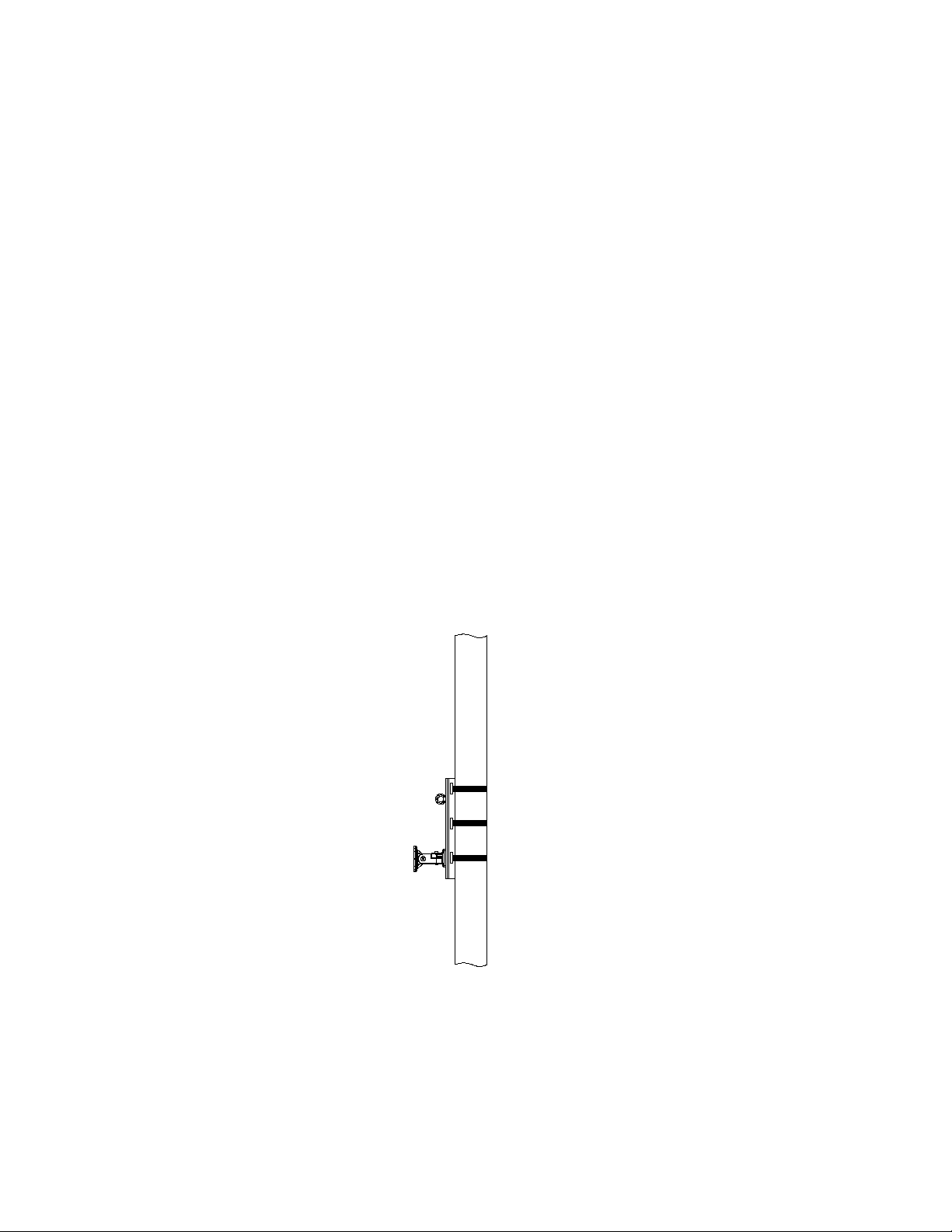
Mount the pole mount section (see Figure 1 above) of the bracket to the pole at the desired
mounting height on the pole. The bracket is mounted to the pole using BAND-IT stainless
steel bands. DO NOT SUBSTITUTE bands of other material or other widths! There are three
locations on the pole bracket for bands.!
IMPORTANT: ALL THREE BAND LOCATIONS MUST BE USED. !
Figure 2 below illustrates the locations for the stainless steel band clamps. !
IMPORTANT: It is REQUIRED that each of the three bands be double-wrapped. Double
wrapping will insure a strong and secure mounting of the bracket to the pole. !
The required banding and buckle material is based on the specific installation environment.
The term “inland” or “non-coastal” refers to the non-industrial and non-marine / oceanfront
environments. The determination of the specific environment is the responsibility of others. !
The required material for “inland” or “non-coastal” environments is:
One Systems, Inc © 2020, All Rights Reserved
For use with 106 models
For use with 104 models
Page 4
"""BAND-IT # C206R9 stainless steel bands; !
"""BAND-IT # C25699 buckles; !
"""BAND-IT # C00169 tensioning tool.!
The stainless steel band is Type 201SS 0.030 inches (0.762 mm) thick and 0.750
inches (19 mm) wide. These banding materials should be used for “inland”
environments.
NOTE: For oceanfront and marine (salt air) environments, the only approved
materials are:
"""BAND-IT # C406R9 stainless steel bands (316 stainless steel)!
"""BAND-IT # C45699 buckles; !
"""BAND-IT # C00169 tensioning tool.!
The stainless steel band is 316 grade stainless 0.030 inches (0.762 mm) thick and
0.750 inches (19 mm) wide.!
WARNING: DO NOT SUBSTITUTE BANDING MATERIAL or banding dimensions.
Installation instructions from BAND-IT should be precisely followed. Operating
instructions are supplied with the tensioning tool (All BAND-IT parts and tools must
Figure 2
One Systems, Inc © 2020, All Rights Reserved
Page 5

be purchased separately. These parts and tools are not supplied by or available
through One Systems, Inc.). The stainless steel banding material, buckles and
tensioning tools are available from the following locations (or through distributors
recommended by these business locations):!
"""" BAND-IT IDEX, Inc. !
"""" 4799 Dahlia St. !
"""" Denver, Colorado 80216 USA. !
"""" 1-800-525-0758!
"""" FELIX PONCE !
""" " Calle Ignacio Zaragonza No. 8 !
""" " Colonia Ahuehuetes Atizapan 52953 !
"""" Edo. de Mexico. !
"""" (52) 555825 8502. !
""""BAND-IT Company Limited!
""""Speedwell Industrial Estate !
"" ""Stavely, Nr. Chesterfield !
""""Derbyshire, S43 3PF England!
""""Home Sales (44) 1246-479479. !
""""Export Sales (44) 1246 479480!
""""BAND-IT Shanghai Sales Office !
""""Wanbao International Business Center #207 !
""""#660 Xinhua Road !
""""Shanghai, China 200052. !
""""021-62826348-308!
""""BAND-IT Clamps (Asia) Pte Ltd. !
""""11 Second Chin Bee Road!
""""Singapore, 61877!
""""(65) 6265- 8853!
2. Attach the appropriate eyebolt to the enclosure. The eyebolt is attached to the
rear (top rear) of the 106.HTH or 106.STH. The eyebolt is attached to the top of the
104.HTH or 104.STH. There are two eyebolts supplied: One is an M8 eyebolt for use
on the 106.HTH or 106.STH. The second eyebolt is an M5 and is for use on the
104.HTH or 104.STH. Use the eyebolt that mates with the specific loudspeaker being
mounted to the PM2.M. !
One Systems, Inc."" www.onesystems.com tel:+1-615-823-1655 fax: +1-615-261-1429
One Systems, Inc © 2020, All Rights Reserved
Page 6
Next, the pan and tilt angles of the PT10.M should be set. !
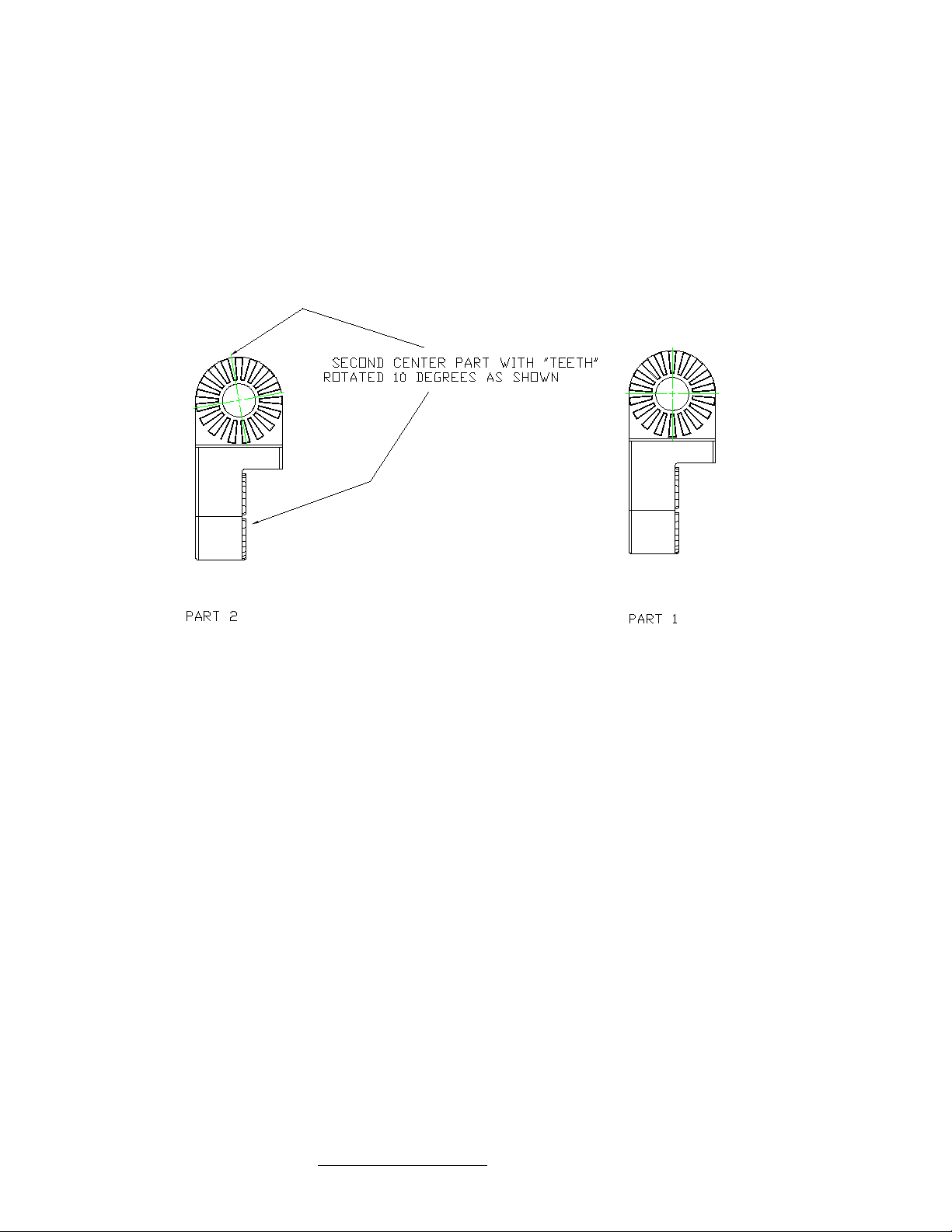
The pan and tilt function allows pan and tilt angles in 10 degree increments. !
NOTE: Two different center pieces are supplied for the PT10.M bracket that will accommodate
20 degree increments, with each center piece incremented by 10 degrees to allow for the 10
degree total pan and tilt adjustment. Select the proper center piece that provides the correct
aiming angles. See the illustration below for details on the center piece of the PT10.M. !
NOTE: DO NOT use both center pieces!
Now, the loudspeaker (104 or 106 models) should be mounted to the loudspeaker bracket
(PT10.M) using the supplied stainless steel bolts and washers (M5). It is recommended that the
desired pan and tilt angles of the loudspeaker be set on the PT10.M portion of the assembly
prior to mounting the loudspeaker. !
The instructions for the PT10.M portion of the PM2.M are also included and should be referred
to when setting the pan and tilt angles. !
3. The PM2.M is supplied with a forged shoulder eyebolt. This bolt is designed to be used
with a secondary cable assembly. This cable assembly must be configured AFTER the
enclosure is mounted on the PT10.M portion of the PM2.M. !
An M8 eyebolt is supplied to allow the 106.HTH or 106.STH enclosure to be fitted with the
supplied cable assembly. An M5 eyebolt is supplied to allow the 104.HTH or 104.STH to be
fitted with the supplied cable assembly. !
INSTALLING THE POLE MOUNT SYSTEM WITH THE CABLE ASSEMBLY IS NOT ALLOWED!!
NOTE: Review all remaining sections before configuring the the cable assembly!!
One Systems, Inc."" www.onesystems.com tel:+1-615-823-1655 fax: +1-615-261-1429
One Systems, Inc © 2020, All Rights Reserved
Page 7
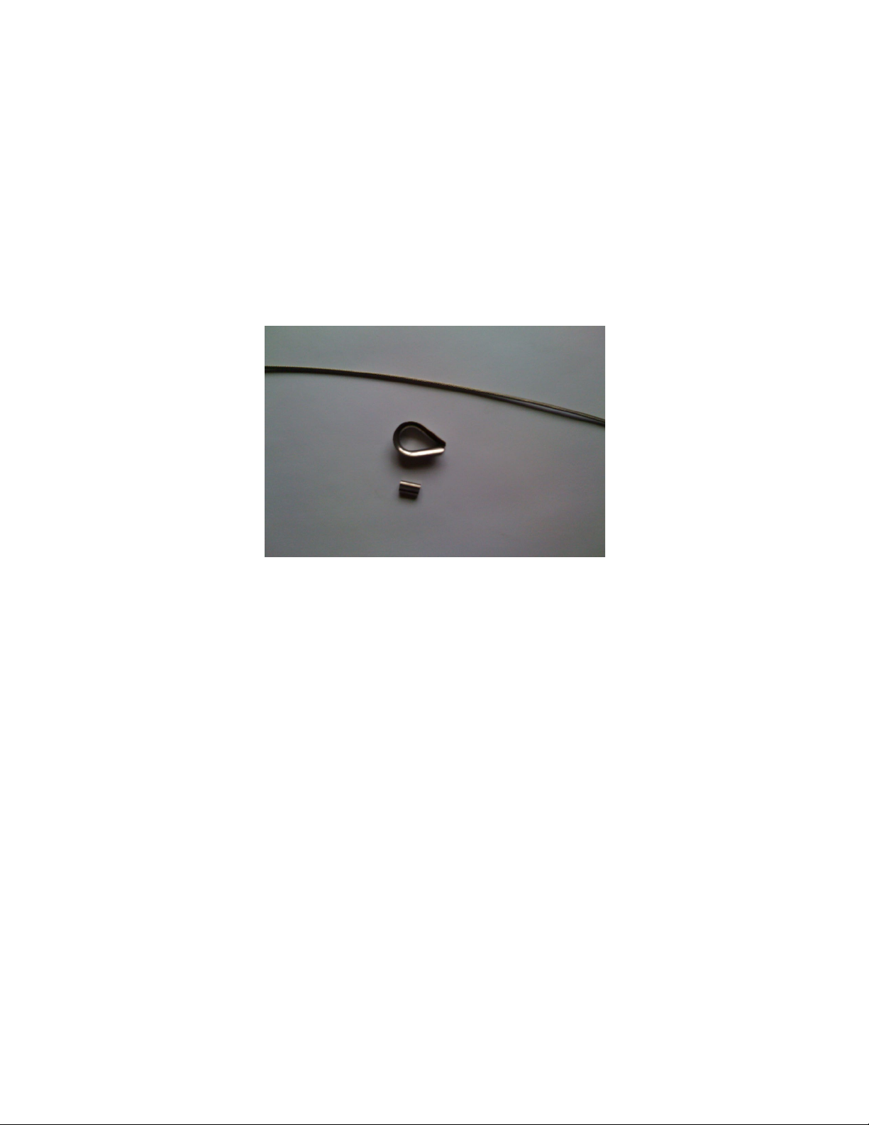
4. Configuration of the supplied cable parts (cable, thimbles and compression sleeves).!
DO NOT PRE-ASSEMBLE THE CABLE.!
The cable assembly MUST be assembled AFTER the enclosure is mounted to the bracket and
the bracket is suspended. See Figure 5 for detail of the finished assembly. !
The cable assembly consists of a length of 1/16-inch 316 stainless steel wire rope, two 1/4-inch
316 stainless steel thimbles and two oval sleeves. The 1/4-inch thimbles must be spread to fit
over each of the eyebolts. The wire rope should be configured and the sleeves crimped AFTER
the thimbles have been installed around the eyebolts. The cable parts are shown in Figure 3.
The length of the wire rope is determined by the pan and tilt angles of the enclosure.
Figure 3
Figure 3 is a photograph of the wire rope section and one of the thimbles as well as one of
the oval sleeves. Make sure that the oval sleeve is crimped using the proper crimping tool. A
close view of the assembly is shown in Figure 5. !
NOTE: A special crimping tool is required for stainless steel compression sleeves. The use of
a tool that is not approved for use with stainless steel compression sleeves will result in
reduced ratings for the wire rope assembly. !
The proper tool to use is produced by:!
Loos and Company, Cableware Division!
901 Industrial Blvd. !
Napes, FL 34104-3715!
1-800-321-5667!
The correct tool is: No. 0-3/64SC!
This tool is designed for use with stainless steel compression sleeves. This tool or the
equivalent must be used when swaging the compression sleeves. When crimping
stainless steel compression sleeves, you MUST use one size smaller diameter on the
crimping tool. For 1/16-inch sleeves and cable, you MUST use a 3/64-inch crimp set.
One Systems, Inc © 2020, All Rights Reserved
Page 8
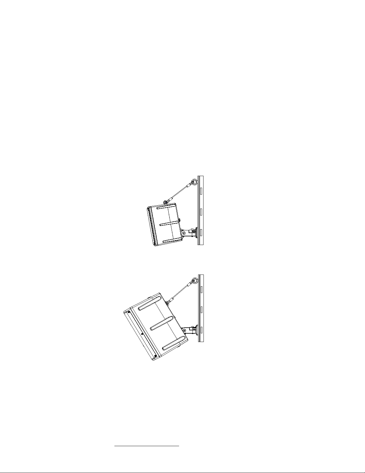
The cable assembly requires the use of a compression tool to securely fit the oval sleeves. One
Systems does not supply this compression tool. The assembly of the cable must be done by
one who is experienced and competent in wire rope assembly and is familiar with the operation
of the required tools. !
See Figures 4 and 5 for details of the proper cable assembly to the enclosure and bracket.
NOTE: This cable assembly should NOT pull the enclosure toward vertical. This cable
assembly must be straight (as shown below) but NOT have any tension. This cable
assembly should NOT take load away from the PT10.M bracket.
Figure 4 shows both the 104 and 106 loudspeaker models mounted to the PM2.M bracket with
the cable assemblies included. The length of the wire rope should be adjusted so that there is
very mild tension on the cable assembly. The cable assembly should not be loose or have any
slack but the cable assembly should not be so tight as to begin pulling the top of the enclosure
back towards vertical. The length of the wire rope is determined by the tilt and pan angles for
the attached enclosure.
One Systems, Inc."" www.onesystems.com tel:+1-615-823-1655 fax: +1-615-261-1429
One Systems, Inc © 2020, All Rights Reserved
Page 9
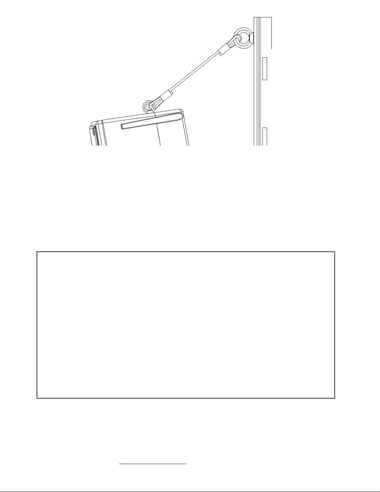
Figure 5
Figure 5 is a close-up view of the wire rope assembly. One end is connected to the M8
eyebolt on the PM2.M and the other end to the eyebolt mounted to the enclosure (a 104 is
shown in Figure 5; for the 106 speaker models, the eyebolt location is on the rear of the
enclosure near the top). !
NOTE: the 1/4-inch thimbles must be spread slightly to fit over the eyebolts and then
compressed.
APPENDIX 1
(PROJECTED AREA VALUES)
The values below should be supplied to the specific pole manufacturer for safety
calculations. These values were determined by adding the projected areas of the high
frequency horns, the woofer cones and ports to the cross-sectional area of the front of
each enclosure listed. Each enclosure will present a different EPA based on wind
direction. The values listed below are for wind loads directly into the front of the
enclosure and represent maximum values. " " " !
"""104.HTH / 104.STH . . . . . 67 in2 (43,000 mm2)
106.HTH / 106.STH . . . . . 136 in2 (88,000 mm2)
One Systems, Inc."" www.onesystems.com tel:+1-615-823-1655 fax: +1-615-261-1429
One Systems, Inc © 2020, All Rights Reserved
 Loading...