

Page 1

1
Marc h 28, 2014
One Systems Natatorium (Indoor Swimming Pool)
Speaker Products Installation Manual
One System s has devel op ed a nar r ow focus, appl icatio n s pecific set of pro du c ts designed
for use in Natatorium (indoor swimming pool) environments. The 108IM/NAT and 112/NAT
are constructed using very high molybdenum content stainless steel for all internal and
external structural rigging members.
Indoor swimming pool environments can present very high relative humidity and harsh
chemical atmospheres. The combination of humidity and airborne chemical composition
restricts the mounting of the 112/NAT or 108/NAT to wall mounting in solid concrete or grout
filled block (CMU) concrete walls ONLY! One Systems does not allow wire rope suspension
of its products in Natatorium environments. Call One Systems regarding direct mounting to
the structural steel of the indoor swimming pool building (Galvanic isolation is required!).
One Systems offers recommendations for installation on solid concrete and grout filled block
walls. Contact One Systems for additional information.
Commonly us e d st ainless steels such as 304-grade and 316 -grade, known as austenitic
steels, offer good corrosion resistance and strength in harsh environments. Marine-grade
(speci fical l y kn ow n as 31 6-gr a de s tainless steel) offers additional protection in salt spray,
ocean front, and cruise ship applications. Unfortunately, these austenitic materials are
susceptible to chloride stress corrosion cracking (SCC). Both 304-grade and 316-grade are
susceptible to SCC. SCC is a particular problem in indoor swimming pool environments and
can result in structural failure of the rigging components. The chlorine based chemicals in
the water react with “human” by-products, suc h as sweat, and produce chloramines. These
chloramines an d hy dr oly zed bypr o duc t s pass into the atmosphere and are deposited on all
surfaces in the Natatorium. They are transported throughout the space via the air handling
system of the venue. This is particularly problematic in areas above the pool surface that are
not routinely washed down or cleaned. Loudspeakers and their associated rigging are
typically mounted far above the “splash zone” and these chloramines are left to settle on
structural surfaces, so that SCC can progress to critical levels. Unfortunately, there are no
establi sh ed t hr e sholds for c hl or am i n e exposur e and ass o ci ated stress levels in th e structur al
members, so SCC can be a significant concern in Natatorium environments. Additionally
there are no visual inspection methods that will detect SCC, so careful monitoring will not
insure th at s tr uctural members are fr ee from this effect. One Systems cannot recommend
the use of stainless steel wire ropes for suspension because of the issues discussed above.
Alternate structural materials, such as aluminum or plated steels, can al so suffer fr om
chloramine attack and other corrosion mechanisms. Fortunately, there are several grades of
stainless steels that are extremely resistance to Chloride SCC. Super austenitic stainless
Page 2

steels consisting of 6% molybdenum are excellent choices. There are several super
austenitic grades that are very strong and well suited for structural members due to their
excellent SCC resistance. These grades are recognized by several European countries as
being the only acceptable stainless steels for use in Natatorium environments where they
are load bearing and above the “splash” zone and not routinely washed or cleaned. One
Systems uses AL6XN (N08367) material. Oth er m ater i als ar e 1. 4547 and 1. 45 29 6%Mo
stainless steels.
NOTE: ONE SYSTEMS DOES NOT RECOMMEND MOUNTING
IT’S PRODUCTS DIRECTLY TO THE NATATORIUM
STRUCTURAL STEEL DUE TO THE
COMPLEXITY OF THE GALVANIC
ISOLATION DESIGN AND THE CORROSIVE NATURE
2
OF THE ENVIRONMENT! (Contact One Systems for
additional information.)
NOTE: THIS MANUAL DOES NOT COVER THE USE OF WIRE
ROPES OR OTHER SUSPENSION METHODS
CONNECTED TO THE STRUCTURAL STEEL OF THE
BUILDING!
NOTE: STAINLESS STEEL WIRE ROPES ARE NOT
RECOMMENDED FOR USE IN
NATATORIUM (INDOOR SWIMMING POOL)
ENVIRONMENTS FOR LOUDSPEAKER SUSPENSION !
NOTE: DO NOT ATTEMPT ANY OF THE OPERATIONS IN THIS
MANUAL IF YOU DO NOT FULLY UNDERSTAND THEN! ALWAYS
CONSULT AN EXPERT WITH EXPERIENCE IN THE OPERATIONS
NOTED IN THIS MANUAL!
Page 3

NOTE: THIS MANUAL CONSISTS OF FOUR (4) SECTIONS:
1. GENERAL ASSEMBLY OF THE LOUDSPEAKER Page 4
2. MOUNTING TO SOLID CONCRETE WALLS Page 6
3. MOUNTING TO CONCRETE BLOCK
A. GROUT FILLED CMU BLOCKS Page 13
3
MOUNTING TO HOLLOW CORE BLOCK IS NOT PERMITTED!
4. General NAT product specif ications Page 25
NOTE: DO NOT ATTEMPT ANY OF THE OPERATIONS IN THIS
MANUAL IF YOU DO NOT FULLY UNDERSTAND! ALWAYS
CONSULT AN EXPERT WITH EXPERIENCE IN THE OPERATIONS
NOTED IN THIS MANUAL!
NOTE: All drilling operations in the manual require masonry bits. Consult
and expert regarding the appropriate bit!
Page 4
U-Bracket Assembly of the 108IM/NAT and 112IM/NAT
The One Systems 108IM/NAT and 112IM/NAT use high molybdenum content stainless steel
for all structural and load bearing points. Both products are supplied with an external “Ubracket” mounti ng c o n figurati on. Thi s is the only ap pr oved mounting method for the NAT
loudspeaker series.
4
NOTE: There are ONLY three (3) mounting points on the NAT enclosures. Two points ar e
used for the ex t er nal U-bracket and the third point may be used as a secondary safety point.
Both the 108IM/NAT and 112IM/NAT are supplied with external U-brackets, bolts and
washers that are required to mount the U-bracket to the enclosure. DO NOT SUBSTITUTE
ANY PARTS USE D TO ATTACH THE U-BRACKET TO THE EN C LOSURE!
The U-bracket (AL6XN material) and associated washers and bolts are supplied and
attach ed to eac h en cl os ure. The bracket must be disassemble d f or ins tal l ation.
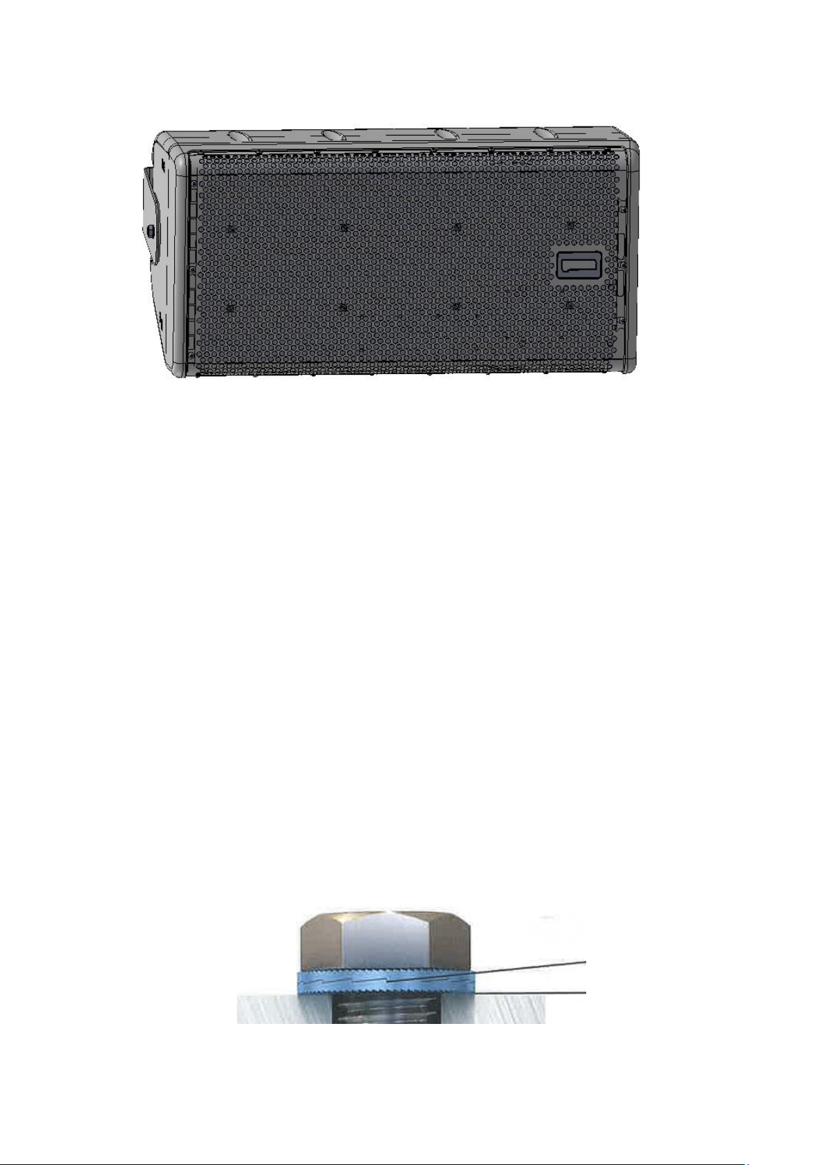
The enclosure and attached U-bracket are shown in the image below. The enclosure is
attach ed to the U Br acket using the supplied AL6XN bolts and Nord-Lock washers. The
108/NAT uses 5/16” bolts and 5/16” (M8) Nord Lock washers. The 112/NAT uses 3/8” bolts
and 3/8” Nord Lock washers. DO NOT SUB STITUTE TH ESE PARTS. The enclosure
should be mou nt ed t o the U br acket AFTER the U bracket has been mounted to either a
solid concrete wall or grout filled block (CMU) wall!
Each Nord Lock washer set consists of TWO parts and BOTH must be used on each bolt
assembly. See the image below. The Nord Lock washer is shown in light blue col or .
Page 5
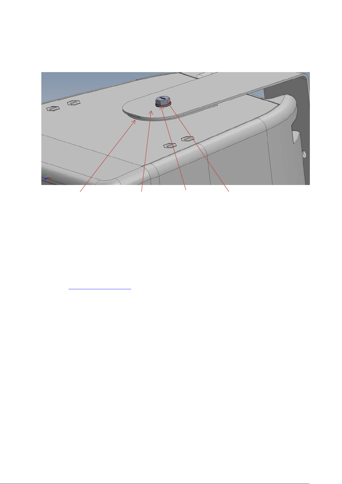
Also note the supplied silicone washer. This large washer must be located between the NAT
enclosure and the U-bracket. This silicone washer will help prevent rotation of the NAT
enclosur e onc e th e des i r e d ai m i ng an gl e is ac hieved.
5
Silicone washer AL6XN bracket Nord Lock washer AL6XN bolt
NOTE: It is critical that the correct torque values be observed when assembling the Ubracket assembly.
The 5/16” bol ts used on the 10 8IM/ NA T U-bracket should be tig ht ened to a torque value of
14ft lb. (19.0Nm)
The 3/8” used on the 112IM/NAT U-bracket should be tightened to a torque value of 24ft lb.
(32.5Nm).
Full installation instructions for the Nord Lock washers may be found on the One Systems
web site (www.onesystems.com
Natatorium section.
) in the Technical Papers/Install Guides under the
NOTE: In d oor swim m ing po ols (N a tatori um s) ca n be very harsh
environments. It is necessary to perform a yearly inspection of all
rigging elements. It is also necessary to perform a yearly visual
inspection on the U-bracket silicone washers (see the image
above). Any signs of degradation or corrosion will require
replacement of any structural elements, including the silicone
washers.
Page 6

Mounting to Solid Concret e Wa l ls:
(Concrete anchors are NOT ALLOWED for use with cinder block
construction)
IMPORTANT: IT IS THE RESPONSIB ILITY OF THE INSTALLER TO
VERIFY THAT THE WALL SURFACE IS STRUCTURALLY CAPABLE
OF SUPPORTING THE PRODUCT AND ALL ASSOCIATED SAFETY
FACTORS AS REQURED BY ALL APPLICABLE CODES AND SAFE
SUSPENSION PRACTICES. THE INSTALLER SHOULD CONSULT
WITH A STRUCTURAL ENGINEER PRIOR TO INSTALLATION TO
INSURE THAT THE WALL SURFACE CAN SUPPORT THE WEIGHT
OF THE 112/NAT OR 108/NAT AND ALL ASSOCIATED RIGGING
AND ALL REQUIRED SAFETY FACTORS. THE COMPOSITION OF
6
THE WALL STRUCTURE
STRUCTURAL ENGINEER PRIOR TO INSTALLATION!
MUST BE REVIEWED BY A
STOP: The approved anchors (Fischer FAZ II 10/10 C) require
a minimum solid concrete wall thickness of 3.937 inches
(100mm). DO NOT mount the NAT loudspeaker to a solid
concrete wall if the wall thickness is not at least 3.937 inches
(100mm) thick!
The NAT products are approved for use with the FAZ II 10/10C
for WALL mounting only! DO NOT MOUNT FROM A CEILING!
STOP: USING FAZ II 10/10 C ANCHORS REQUIRES A
TORQUE WRENCH CAPABLE OF 33 FT-LBS (45MN) OF
TORQUE. THESE ANCHORS MUST BE TORQUED TO THIS
VALUE. DO NOT INSTALL IF YOU DO NOT HAVE A
TORQUE WRENCH!
NOTE: The anchors referenced below are for use in solid concrete ONLY!
DO NOT use with cinder block (CMU) wall construction!
NOTE: ALL installation instructions below are guidelines. It is necessary to read the
additional installation instructions provided by Fischer. Additional instructions may
be found on the One Systems web site in the Documentation section. The Natatorium
section is found in the Tech Papers/Install guides section under the onesystems.com
Documentation Tab. This document is ESR 2948.
Page 7

IT IS NECESSARY TO READ ESR 2948 AND UNDERSTAND THIS
DOCUMENT PRIOR TO INSTALLATION.
INSURE THAT THE SOLID CONCRETE CONFORMS TO SECTION
5.0 OF ESR 2948 AND OBSERVE ALL REQUIREM ENTS IN THIS
“CONDITIONS OF USE” SECTION!
BRACKET LOCATION ON SOLID CONCRE TE WALLS
IMPORTANT NOTE: The mounting holes in the concrete
MUST be drilled at least 8 inches (203.2mm) away from any
edges or openings in the solid concrete wall! DO NOT drill
the bracket mounting holes in the solid concrete where
wall edges or openings in the wall are closer then 8 inches
(203.2mm)!
7
Solid Concrete Anchors:
If the 108IM/NAT or 112IM/NAT are to be mounted on a solid concrete surface, then
approved concrete anchors must be used. The ONLY approved source for concrete anchors
is Fischer Fixings LLC. Do not substitute any other anchors!
The approved concr ete anchor s ar e as fol low s :
108IM/NAT Fischer FAZ II 10/10 C (the “C” is a designator for 1.4529 6% Mo stainless
steel)
112IM/NAT Fischer FAZ II 10/10 C (the “C” is a designator for 1.4529 6% Mo stainless
steel)
Page 8
NOTE: ONLY HORIZONTAL MOUNTING IS PE RMITTED WHEN MOUNT ING ON SOLID
CONCRETE WAL LS! DO NOT MOUNT THE U-B RACKET IN A VERTICAL
ORIENTATION!
DO NOT MOUNT VERTICALLY ON SOLID CONCRETE WALLS
MOUNT BRACKET AND ENCLOSURE HORIZONTALLY ONLY!
NOTE: When mounting to a solid concrete wall ONLY one anchor per side on the U bracket
is permitted. DO NOT USE MORE THEN ONE ANCHOR PER SIDE (see im ag e below)
NOTE: Only certain holes on the U-bracket may be used and
8
ONLY horizontal mounting is permitted. Dril l only ONE
mounting hole per side.
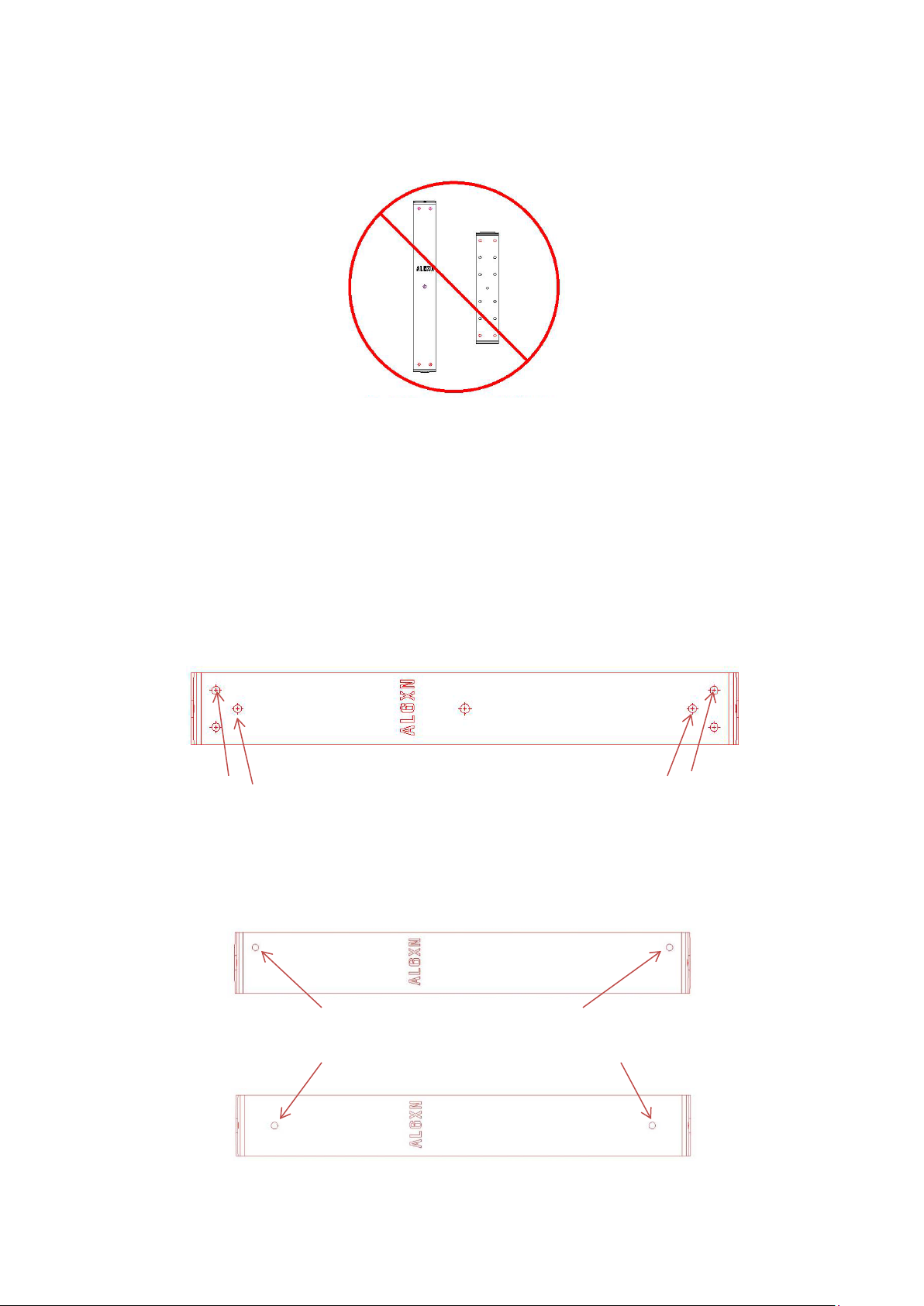
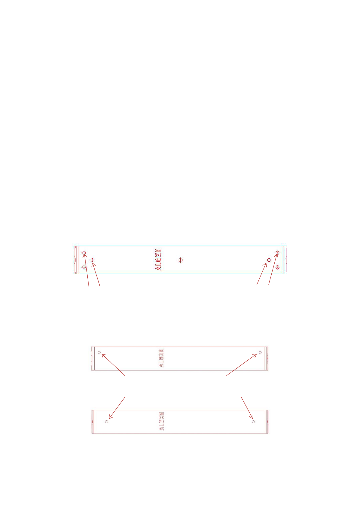
The 112/NAT U-bracket is shown below
Use ONLY one hole per side. Use either of the holes shown BUT not both holes.
NOTE: DO NOT DRILL MORE THEN ONE HOLE PER SIDE!
The images below show the mounting holes allowed.
Use these two holes ONLY!
OR
Alternately these two holes ONLY!
Page 9
9
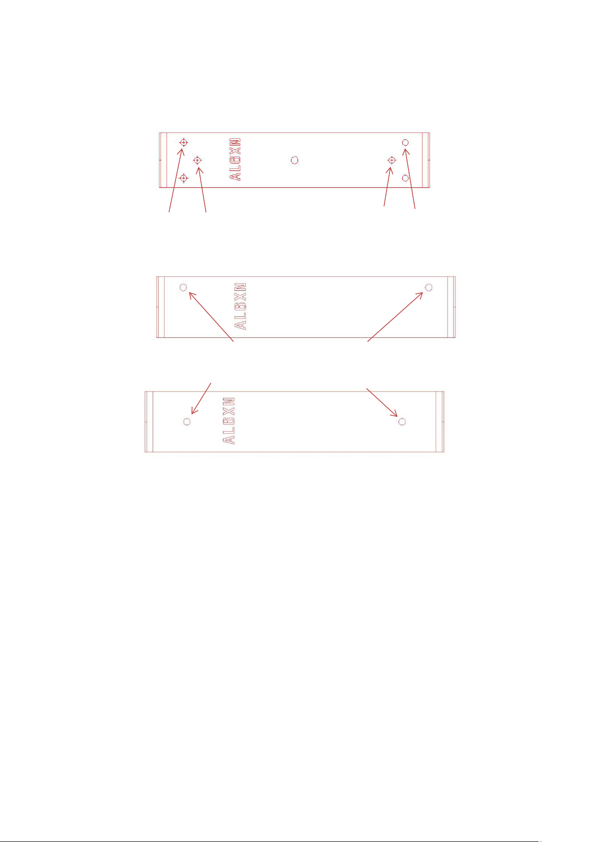
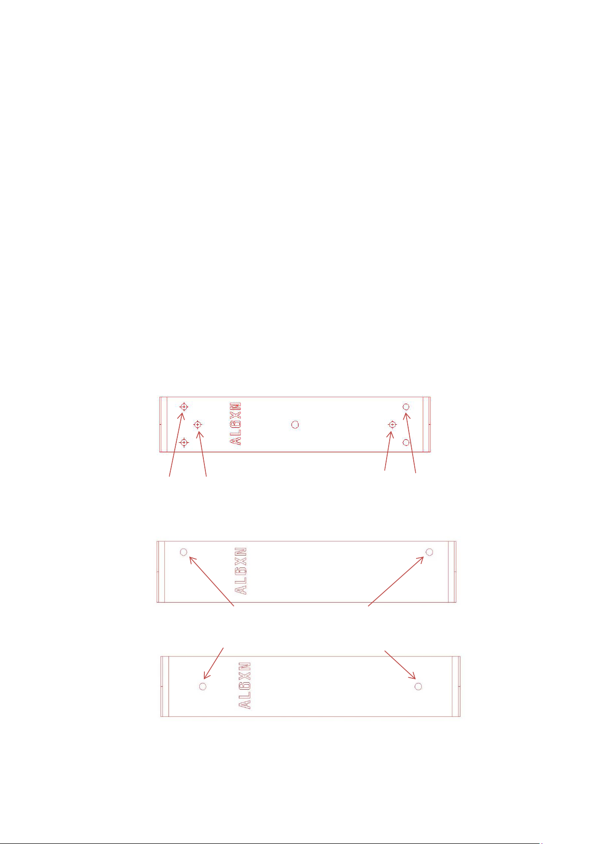
The 108/NAT U-bracket is shown below
Use ONLY one hole per side. Use either of the holes shown BUT not both holes.
NOTE: DO NOT DRILL MORE THEN ONE HOLE PER SIDE!
The images below show the mounting holes allowed.
Use these two holes ONLY !
OR
Alternately these two holes ONLY
The required hole depth is 3 11/32 inches (85mm) and should be verified
prior to installation of the FAZ II 10/10C anchor! INSURE THAT THE
HOLE IS THE CORRECT DEPTH! This hole should be perpendicular
to the surface of the wall. DO NOT drill at an angle!
NOTE: Avoid drilling into rebar. Rebar locators may be rented from
many sources to determine the location of rebar in the solid concrete.
Page 10

10
To install the FAZ II 10/10C anchor follow the steps listed below:
1. Create the drill hole. 3 11/32 (3.343 inches) deep (85mm) and 10mm diameter.
INSURE THAT THE HOLE IS THE CORRECT DEPTH!
This hole should be strai ght an d perpendicular to the surface of the wall.
DO NOT drill at an angle!
solid concrete walls!
Consult with someone with experience drilling into
THE ACTUAL BRACKET LOCATION MUST BE AS NOTED ON PAGE
7 IN THE SECTION “BRACKET LOCATION ON SOLID CONCRETE
WALLS”!
NOTE: The hole diameter MUST be drilled with a 10mm diameter bit. Do not
substitute an imperial diameter. A metric 10mm diameter drill bit must be used!
ELECTRIC D RILLS MUST BE USED AND IN ROTATION MODE ONLY!
Note: One Systems offers the NASH 1009008A 10mm drill bit. This drill may be
sourced from One Systems Nashville.
2. Clean the hole completely using the tool shown below. It is important to
completely clean the hole. The cleaning operation should be performed several
times!
NOTE: It is critical to completely clean the drilled hole. It is necessary to follow the
anchor manufacturers cleaning instructions. See the recommended Fischer tool
(89300) below and may be sourced directly thru Fischer.
Page 11

11
NOTE: The bracket images shown below are for illustration purposes only. In actual
assembly the NAT external U-bracket for the 108/NAT or 112/NAT must be used!
IMP ORTANT: BEF ORE DRIVING THE FAZ II 1 0/ 10 C ANCHOR INTO THE HOLE , INSURE
THAT THE HEX NUT IS IN THE PROPER POSITION. THE CORRECT POSITION OF THE
HEX NUT IS W HEN 5/64 inches to 1/8
BOLT IS PROJECT ING BEYOND THE END O F T HE NUT.
th
inches (2mm TO 3 mm) OF THE THREADED
2mm to 3mm this end of thread exposed
3. Mount the 108/NAT or 112/NAT U-bracket over the holes and drive the FAZ II 10/10C
anchor in place as shown.
The FAZ II 10/10C is driven in place as shown below. The NAT U-bracket must be
in place before the anchor is driven into the hole!
4. Apply the required torque as shown below in the center image. The required
torque is 33ft lbs (45 NM).
NOTE: The FAZ II 10/10 C is supplied with the correct washer and nut. DO NOT
SUBSTITUTE ANY PARTS!
Additional instructions for inst all i n g these concrete anchors are found on the One Systems
web site (www.onesystems.com
Guides”. The document is ESR 2948. THIS DOCUMENT MUST BE READ AND
UNDERSTOOD PRIOR TO INSTALLATION!
) in the Documentation section under “Tech Papers/Install
Page 12

12
NOTE: The required torque on the FAX II 10/10C M10 nut is 33 ft-lbf
(45 Nm). DO NOT EXCEED THI S TO RQUE BUT INSURE THAT THIS
TORQUE IS APPLIED.
Once the FAZ II 10/10C nut is tightened to the specified torque, DO NOT re-torque
or tighten further. DO NOT re-torque later !
NOTE: DO NOT USE ANY THREAD LOCKER WITH THIS PRODUCT! Use ONLY
the parts supplied!
The contact information for Fischer is:
Fischer Fi xi n gs LLC
62 Orange Ave
Suffern, New York 10901
www.fischerfixingsusa.com
Phone: + 1-845-504-5098
NOTE: These anchors are NOT PERMITTED for use with “cinder block”
(CMU) construction! See information below for grout filled masonry
block.
Below is what is nee ded to hang a single 112/NAT or 108/NAT cabinet in a solid concrete
wall:
2 ea. NASH 1009007A FAZ II 10/10C Fischer anchors. One Systems Nashville supplied.
1 ea. Fischer air tool (Fischer part 89300…this part is re-useable). Fischer supplied
1ea. NASH 1009008A 10mm Masonry Drill Bit. One Systems supplied
Page 13

13
MOUNTING TO GROUT FILLED CONCRE TE BL O CK
IMPORTANT: IT IS THE RESPONSIBILITY OF THE INSTALLER TO
VERIFY THAT THE WALL SURFACE IS STRUCTURALLY CAPABLE
OF SUPPORTING THE PRODUCT AND ALL ASSOCIATED SAFETY
FACTORS AS REQURED BY ALL APPLICABLE CODES AND SAFE
SUSPENSION PRACTICES. THE INSTALLER SHOULD CONSULT
WITH A STRUCTURAL ENGINEER PRIOR TO INSTALLATION TO
INSURE THAT THE WALL SURFACE CAN SUPPORT THE WEIGHT
OF THE 112/NAT OR 108/N AT AND ALL ASSOCIATED RIGGING
AND ALL REQUIRED SAFETY FACTORS. THE COMPOSITION OF
THE WALL STRUCTURE
STRUCTURAL ENGINEER PRIOR TO INSTALLATION!
MUST BE REVIEWED BY A
NOTE: MOUNTING ON HOLL OW CORE BLOCK(CMU) IS
NOT PERMTTED! DO NOT MOUNT ON HOLLOW CORE
BLOCK!
MOUNT ON GROUT FILLED BLOCK ONLY!
STOP! THE BLOCK SIZE MUST BE 16 INCHES X 8 INCHES
X 8 INCHES! (OR METRI C EQUIVALENT ) DO NOT USE
SMALLER BLOCK SIZE. DO NOT ATTEMPT TO MOUNT THE
112NAT OR 108NAT TO SMALLER BLOCK SIZES!
THE BLOCK (CMU) MUST BE ASTM C-90 OR EQUIVALENT!
A TORQUE WRENCH IS REQUIRED F OR THIS
INSTALLATION!
BRACKET LOCATION ON GROUT FILLED BL O CK WALLS!
The mounting holes in the grout filled concrete block
MUST be drilled at least 12 inches (305mm) away from any
edges or openings in the grout filled block wall! DO NOT
drill the bracket mounting holes in the grout filled CMU
(concrete masonry unit) block where wall edges or
openings in the wall are closer then 12 inches (305mm)!
Page 14

14
One Systems requires ONLY horizontal mounting to grout filled concrete block
(CMU). Both the 112/NAT and 108/NAT must be mounted horizontally as shown
below.
NOTE: ONLY HORIZONTAL MOUNTING IS PE RMITTED WHEN MOUNT ING ON GROUT
FILLED BLOCK WALLS! DO NO T MOUNT THE U BRACK ET IN A VER TICAL
ORIENTATION!
DO NOT MOUNT VERTICALLY ON GROUT FILLED BLOCK WALLS
MOUNT BRACKET AND ENCLOSURE HORIZONTALLY ONLY!
DO NOT MOUNT THE 112/NAT OR 108/NAT VERTICALLY. MOU NT ONLY AS
SHOW N BELOW! Note the horizontal orientation of the U-Bracket!
THE ACTUAL BRACKET LOCATION MUST BE AS NOTED ON PAGE
13 IN THE SECTION “BRACKET LOCATION ON GROUT FILLED
BLOCK WALLS”!
Page 15

The 112/NAT and 108/NAT must be mounted by drilling thru the entire grout filled
block as shown below. It is necessary to drill completely thru the grouted block and
run the 3/8”-16 AL6XN all thread thru the block. Large AL6XN backing plates for
structural support are required. The front and back sides of the block are shown in
the images below. The drilled hole should be thoroughly cleaned prior to inserting
the 3/8”-16 AL6XN all threaded rod.
IMPORTANT NOTE: THE HOLE MUST BE DRILLED STRAIGHT. INSURE THAT
THE HOLE IS NOT DRILLED AT AN ANGLE. THE NORD-LOCK WASHERS AND
NUTS MUST BE F LAT AND PARALLEL W ITH BOTH TH E U BRACKET AND
BACKING PLATES FOR THE NORD LOCK WASHERS TO FUNCTION
PROPERLY. INSURE THAT THE HOLE IS NOT DRILLED AT AN ANGLE!
Consult with someone with experience drilling into grout filled block walls!
The front side is shown in the image below. This image shows the block wall and
NAT U-bracket.
15
SEE PAGE 13 FOR PROPER LOCATION OF THE BRACKET ON THE WALL IN
THE SECTION LABELED “BRACKET LOCATION ON GROUT FIL LED BLOCK
WALLS”!
The rear side of the mounting configuration is shown in the image below. Note the
required use of the large AL6XN “backing plates”. These plates MUST be used.
BACKING PLATE LOCATION NOTE: Insure that the backing plates touch a single
block only! Do not allow the backing plates to bridge across to a second CMU block!
AL6XN backing plates on “rear” section
Page 16

16
A side view of the assembly is shown below. NOTE: The silicone sealing caulk is not
shown on this image but is required for this assembly.
MOUNT ON GROUT FILLED BLOCKS ONLY!
An image of the Nord-Lock washer set is shown below. Note the two parts of each
washer set and the orientation of the washer parts. Add it iona l inform ation for the
Nord-Lock washers may be found on the One Systems web site in the Natatorium
section of the Documents section under “Tech papers/Install guides”.
The image below shows the location of the silicone caulk.
NOTE: USE ONLY BOSS 801 SILICONE. DO NOT SUBSTITUT E ANY OTHER
MATERIAL OR ANY OTHER BRAND. USE BOSS 801 SILICONE ONLY!
The application of the Boss 801 silicone is the final step of the mounting process.
Apply the Silicone to the proper location AFTER the U-bracket and backing plates
have been installed and tightened to the specified torque. Pages 19 thru 21 describe
the installation of the 112/NAT and pages 22 thru 24 describe the installat ion of the
108/NAT. DO NOT proceed to these pages yet. It is necessary to continue reading
the information below prior to beginning the actual bracke t instal lation.
Apply a generous bead of the Boss 801 silicone caulk around the OUTSIDE
perimeter of the NAT U bracket and the block wall. Also apply a generous bead of
Boss 801 silicone caulk around the OUTSIDE perimeter the AL6XN backing plates
and the wall as shown below.
Page 17

NOTE: DO NOT APPLY TH E BOSS 801 SILICONE BETWEEN THE U BRACKET
AND THE WALL OR BETWEEN THE BACKIN G PLATE AND THE WALL. THE
SILICONE BEAD SHOULD BE APPLIED AROUND THE PERIMETER ONLY!
17
MOUNT ON GROUT FILLED BLOCKS ONLY!
Page 18

18
The image below illustrates the location of the Boss 801 silicone (shown
in blue color). The entire perimeter should be caulked. Do not apply the
silicone between the U-bracket and the wall or the backing plate and the
wall.
Note the location of the silicone beads shown in blue above. The correct location
forms a fillet as shown above. Do not apply between the wall and the U-bracket or
wall and backing plate.
The U-Bracket side includes one U-bracket, two AL6XN nuts, two Nord-Lock
washers, and a bead of Boss 801 silicone caulk.
The rear side consists of two AL6XN backing plates, two AL6XN nuts, two Nord-Lock
washers, and two beads of Boss 801 silicone caulk (one bead aroun d each backing
plate).
There are ONLY two AL6XN all thread rods used in the assembly, ONE per side
only!
NOTE: All of the i n for m a ti o n fr om pa ge 13 t hru page 18 applies to
BOTH the 112/NAT and 108/NAT. The additiona l informatio n fo u nd
below in pages 19 thru 21 is specific to the 112/NAT. The
information found below in pages 22 thru 24 is specific to th e
108/NAT.
THE INFORMATION ON PAGES 13 THRU 18 MUST BE READ
BEFORE PROCEEDING TO THE SPECIFIC BRACKET
INSTALLATION SECTIONS!
Page 19
19
MOUNTING THE 112/NAT
NOTE: It is important to properly locate the NAT U-bracket on
the block wall. The 112/NAT and 108/NAT each require a
different mounting location relative to the concrete block cells.
The drilled thru hole must NOT be located near the edges of
the block or in the grout between the blocks. See the section on
page 13,
WALLS
“BRACKET LOCATION ON GROUT FILLED BLOCK
” for additional details.
NOTE: MOUNTING ON HOLLOW CORE BLOCK IS NO T
PERMTTED! DO NOT MOUNT ON HOLLOW CORE BLOCK!
MOUNT ON GROUT FILLED BLOCK ONLY!
NOTE: Only certain holes on the U-bracket may be used and
only horizontal mounting is permitted. Drill only one mounting
hole per side.
Use ONLY one hole per side. Use either of the holes shown BUT not both holes.
NOTE: DO NOT DRILL MORE THEN ONE HOLE PER SIDE!
The images below show the mounting holes allowed.
Use these two holes ONLY!
OR
Alternately these two holes ONLY!
Page 20
20
The required hole size is 1/2 inches (12.7mm). Drill completely thru the concrete
block. Use a rotary drill only! (One Systems does not supply this 1/2” masonry drill)
NOTE: Avoid drilling into rebar. Rebar locators may be rented from
many sources to determine the location of rebar in the concrete block.
IMPORTANT NOTE: THE HOLE MUST BE DRILLED STRAIGHT. INSURE THAT
THE HOLE IS NOT DRILLED AT AN ANGLE. THE NORD-LOCK WASHERS AND
NUTS MUST BE FLAT AND PARALLEL WITH BOTH THE U BRACKET AND
BACKING PLATES FOR THE NORD LOCK WASHERS TO FUNCTION
PROPERLY. INSURE THAT THE HOL E IS NOT DRILLED AT AN ANGLE!
Consult with someone with experience drilling into grout filled block walls!
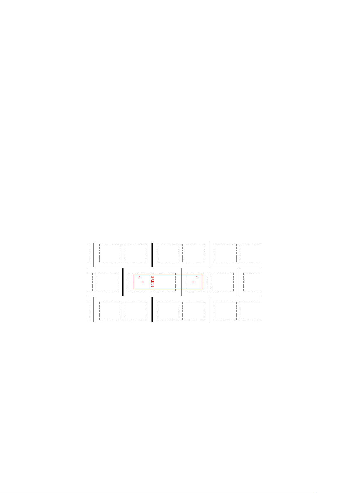
The location of the holes in the blocks (one per side) is shown below. The two holes
shown per side only represent the allowed mounting locations. ONLY one hole
per side shou ld be dr ill ed!
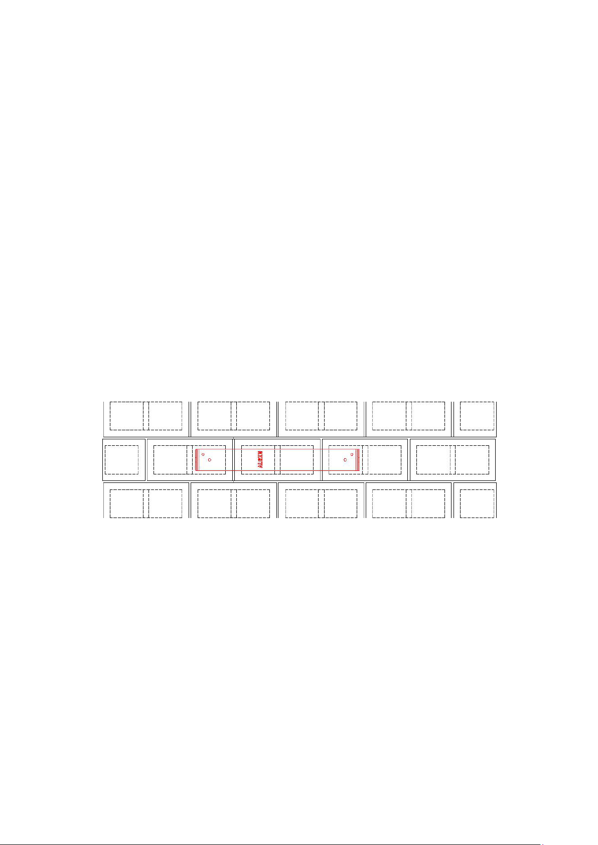
NOTE: Please note the location of the bracket relative to the structure of the blocks.
The 1/2” mounting holes (only one per side) must NOT be drilled between the
blocks. Insure that the holes are drilled in the block “cores” only and away from the
block vertical members!
Please note in the image above how the 112/NAT U-bracket spans across 3
individual concrete blocks. The dashed lines represent the internal structure of the
individual blocks. Only drill the holes in the “core” areas as shown above!
NOTE: It is critical to note the lo catio n of the U-bracket relative to the
individual blocks when mounting the 112/NAT.
When tightening the nuts a torque of 21 ft. lbs (28.5Nm) should be
used.
washer pairs before tightening to minimize settlements. KEEP BOTH NUTS
SECURED WHILE TIGHTENING!
NOTE THE APPR OXIMATE LOCATION OF THE BACKING PLATES ON PAG E 21.
When turning the nuts turn both nuts in order to close the cams on both
Page 21
21
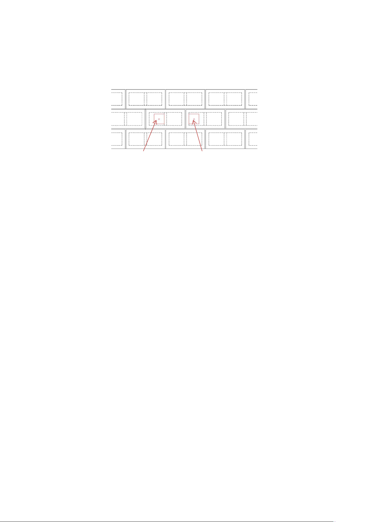
The image below shows the rear of the block wall with the approximate location of
the rear AL6XN backing plates. The backing plates are shown in red.
Approximate location of 112/NAT rear backing plates on grout filled block wall.
BACKING PLATE LOCATION NOTE: Insure that the backing plates touch a single
block only! Do not allow the backing plates to bridge across to a second CMU block!
All parts except the Boss 801 silicone are available from One Systems.
To mount either a 112/NAT the following parts are required:
2 ea. NASH1009010A 3/8”-16 AL6XN all thread
2 ea. NASH 1009011A Backing plate
4 ea. NASH1009006A Nord-Lock 3-8inSPSS-254 washer sets (each set
consists of two parts bonded together!)
4 ea. NASH1009002A 3/8”-16 AL6XN nuts
1 ea. Boss 801 silicone caulk (contact Boss at 1 800 928 2677 for local distributors
or sources. Call this number for International sources as well.)
Page 22
22
MOUNTING THE 108/NAT
NOTE: MOUNTING ON HOLLOW CORE BLOCK IS NO T
PERMTTED! DO NOT MOUNT ON HOLLOW CORE BLOCK!
MOUNT ON GROUT FILLED BLOCK ONLY!
NOTE: It is important to properly locat e the NAT U-bracket on
the block wall. The 112/NAT and 108/NAT each require a
different mounting location relative to the concrete block cells.
The drilled thru hole must NOT be located near the edges of
the block or in the grout between the blocks. See the section on
page 13,
WALLS
“BRACKET LOCATION ON GROUT FILLED BLOCK
” for additional details.
NOTE: Only certain holes on the U-bracket may be used and
ONLY horizontal mounting is permitted. Dril l only ONE
mounting hole per side.
Use ONLY one hole per side. Use either of the holes shown BUT not both holes.
NOTE: DO NOT DRILL MORE THEN ONE HOLE PER SIDE!
The images below show the mounting holes allowed.
Use these two holes ONLY!
OR
Alternately these two holes ONLY!
Page 23
23
The required hole s ize is 1/2 inches (12.7mm). Drill completely thru the concrete
block. Use a rotary drill only! (One Systems does not supply he 1/2” masonry drill).
NOTE: Avoid drilling into rebar. Rebar locators may be rented from
many sources to determine the location of rebar in the concrete block.
IMPORTANT NOTE: THE HOLE MUST BE DRILLED STRAIGHT. INSURE THAT
THE HOLE IS NOT DRILLED AT AN ANGLE. THE NORD-LOCK WASHERS AND
NUTS MUST BE FLAT AND PARALLEL WITH BOTH THE U BRACKET AND
BACKING PLATES FOR THE NORD LOCK WASHERS TO FUNCTION
PROPERLY. INSURE THAT THE HOLE IS NOT DRILLED AT AN ANGLE!
Consult with someone with experience drilling into grout filled block walls!
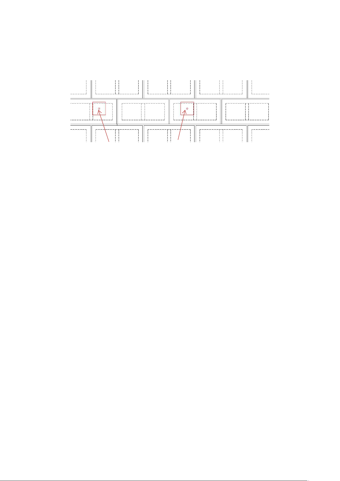
The location of the holes in the blocks (one per side) is shown below.
The two holes shown per side in the image below only rep resent the allow ed
mounting locations. ONLY one hole per side should be drilled!
NOTE: Please note the location of the bracket relative to the structure of the blocks.
The 1/2” mounting holes (only one per side) must NOT be drilled into the grout
between the blocks. Insure that the holes are drilled in the block “cores” only and
away from the block vertical members!
Please note in the image above how the 108/NAT U-Bracket spans across 2
individual concrete blocks. The dashed lines represent the internal structure of the
individual blocks. Only drill the holes in the “core” areas as shown above!
NOTE: It is critical to note the location of the U-Bracket relative to the
individual blocks when mounting the 108/NAT.
When tightening the nuts a torque of 21 ft. lb. (28.5Nm) should be
used.
washer pairs before tightening to minimize settlements. KEEP BOTH NUTS
SECURED WHILE TIGHTENING!
NOTE THE APPR OXIMATE LOCATION OF THE BACKING PLATES ON PAG E 24.
When turning the nuts turn both nuts in order to close the cams on both
Page 24
24
The image below shows the rear of the block wall with the approximate location of
the rear AL6XN backing plates. The backing plates are shown in red.
Approximate location of 108/NAT rear backing plates on grout filled block wall.
BACKING PLATE LOCATION NOTE: Insure that the backing plates touch a single
block only! Do not allow the backing plates to bridge across to a second CMU block!
All parts except the Boss 801 silicone are available from One Systems.
To mount either a 108/NAT the following parts are required:
2 ea. NASH1009010A 3/8”-16 AL6XN all thread
2 ea. NASH 1009011A Backing plate
4 ea. NASH1009006A Nord-Lock 3-8inSPSS-254 washer sets (each set
consists of two parts bonded together!)
4 ea. NASH1009002A 3/8”-16 AL6XN nuts
1 ea. Boss 801 silicone caulk (contact Boss at 1 800 928 2677 for local distributors
or sources). Call this number for International distributors as well.)
Page 25

25
108IM/NAT
The 108IM/NAT features an 8” ( 20 3m m ) low fre qu enc y dr i v er and an ETS bas e d hi gh
frequency compression driver. The 108IM/NAT HF driver is a very high performance and
medium for m at des i g n. T he 1 08IM/NAT is supplie d with two high fr eq uency horn s , bot h of
which are ful l y rotatabl e and interchangeable. The ETS-64 is a 60 degree by 40 degree
wave guide and is mounted in the enclosure as supplied by the factory. The 108IM/NAT also
includes an ET S-105/60 hor n that feat ur es a 10 5 de gr ee by 60 degr ee aco us ti cal radi ation
pattern . Th e pr ocedure for ch a ngi n g the high frequency horns is found on the One Systems
web site in the documentation section under the “tech papers and install guides” tab. (One
Systems Interchangeable High Frequency Horns (For 108IM loudspeaker).
The 108IM/NAT is a high performance system specifically designed for use in indoor
swimm i ng pool envi r o nm e nt s. The desig n features a peak power ha ndl ing ratin g o f 80 0
watts and is av ailable in an 8 ohm (lo Z) confi gur a tion only. There ar e only tw o m ou nti ng
points (AL-6XN) and the 108/NAT may be suspended using the supplied “U” bracket only.
(Note: there is a third point on the rear of the enclosure for use as a secondary safety.)
The 108IM/NAT is supplied with an external weather cover and IP68 gland nut for simple
wiring. The input is via a barrier strip. The enclosure is available in white color.
The 108IM/NAT is a closed box design. This acoustic configuration allows for simple low
frequency equalization using mixer strip EQ or other shelving style filters.
112IM/NAT
The 112IM/NAT features a 12” (305mm) low frequency driver and an ET based large format
high frequency compressi o n dr i ver . T he 11 2IM/NAT HF driver is a very high performance
large format design. The 112IM/NAT is supplied with a high frequency horn that is fully
rotatable and interchangeable. The ET64 is a 60 degree by 40 degree wave guide and is
mounted in the enclosure as supplied by the factory. The 112IM/NAT can als o be fitted with
the ET-105/60 horn that features a 105 degree by 60 degree acoustical radiation pattern (the
ET-105/60 is not incl ud ed in the fac tor y su ppl i e d 112IM/NAT, but may be ordered from One
Systems at no additional charge). T he pr ocedure for changing the high frequency horns is
found on the One Systems web site in the documentation sectio n un der t h e “tech papers
and install guides” tab (One Systems Interchangeable High Frequency Horns for 112IM,
115TW and 11 5RW horns lou dsp eakers) . This same procedure should be followed for the
112IM/NAT.
The 112IM/NAT is a high performance system specifically designed for use in indoor
swimm i ng pool envi r o nm e nt s. The desig n features a peak power ha ndl ing ratin g o f 32 00
watts and is av ailable in an 8-ohm (lo Z) configuration only. There are only two mounting
points (AL-6XN stainless steel) and the 112IM/NAT may be suspended using the supplied Ubracket onl y .( Note: there is a third point on the rear of the enclosure for use as a secondary
safety.) The enclosure is only available in white color.
The 112IM/NAT is supplied with an external weather cover and IP68 gland nut for simple
wiring. The input is via a barrier strip.
Page 26

The 112IM/NAT is a closed box design. This acoustic configuration allows for simple low
frequency equalization using mixer strip EQ or other shelving style filters.
108IM/NAT Features and Benefits
Designed for use in Natatorium (Indoor Swimming Pool) Environments
8-Inch Two-Way High-Performance Sealed Enclosure Design
Two Fully Rotatable and Interchangeable High Frequency Horns
Available in White Finish
Low Impedance (8-Ohm) High Pow er Design
U-bracket Suspension Suppli ed
108IM/NAT Specifications
26
Frequency Response 65Hz – 16kHz
Coverage Pattern 60 X 40 (ETS60/40)
105 X 60 (ETS105/60)
Passive Crossover 2000Hz (ET S 60x 40)
1600Hz (ETS 10 5x60)
Inputs Barrier Strip (Full Range Only)
System Sensitivity 92dB (1 watt - 1 meter)
Power Handling 200 watts continuous
400 watts program
800 watts peak
Nominal Impedance 8-ohms
Low Frequency One Systems ONE8-134 Woofer
High Frequency One Systems ETS Compression Driver
Suspension/Mounting Points 2 Each U-bracket mount only (Supplied) 5/16”
1 Safety Point on enclosure rear
Enclosure Dimensions 483.8mm x 243mm x 271mm
19” x 9.6” x 10.7”
Weight 16.5kg (36.3 lb.) including U Bracket
Optional Accessories No Optional Acces s or i es All owed
Page 27

112IM/N AT Features and Benefits
Designed for use in Natatorium (Indoor Swimming Pool) Environments
12 Inch Two Way High Performance Sealed Enclosure Design
Fully Rotatable and Interchangeable High Frequency Horns
Available in White Finish
Low Impedance (8-Ohm) High Power Design
U-bracket Suspension Suppli ed
112IM/NAT Specifications
Frequency Response 60Hz – 16kHz
Coverage Pattern 60 X 40 (ETS6 0/ 40)
Available 105 X 60 (E TS105/60 )
Passive Crossover 1800Hz (ET 60x40)
1300Hz (ET 105x60)
Inputs Barrier Strip (Full Range Only)
System Sensitivity 96dB (1 watt – 1 meter)
Power Handling 800 watts continuous
1600 watts program
3200 watts peak
Nominal Impedance 8-ohms
Low Frequency ONE SYSTEMS 12I/O-1 Woofer
High Frequency ONE SYSTEMS ET-1F Compression Driver
Suspension/Mounting Points 2 Each U-bracket mount only (Supplied) 3/8”
1 Safety Point on Enclosure rear
Enclosure Dimensions 749mm x 368mm x 414mm
29.5” x 14.5” x 16 .3”
Weight 36.6kg (80.7 lb.) including U-bracket
Optional Accessories No Optional Accessories Allowed
27
 Loading...