

Page 1

108.HTH Interchangeable
High Frequency Horns
One Systems® offers several high-performance, Direct Weather capable loudspeakers that
incorporate fully rotatable and interchangeable high frequency horns. The 108.HTH is a highperformance, compact 8-inch two-way professional loudspeaker system that is shipped with
two high-frequency horns: a 60o x 40o horn (ETS-60/40) is factory-installed in the speaker and
a 105o x 60o horn (ETS-105/60) is also included in the shipping carton. Both horns can be
rotated to achieve optimal coverage patterns for horizontal or vertical orientation of the
speaker. "
Since each horn produces different acoustic loading for the compression driver, the 108.HTH’s
passive crossover must be “re-configured” to provide the proper crossover frequency, as well
as the proper amplitude shading for each horn pattern. This process is very simple and
straightforward."
The following steps are required in order to accomplish this process:"
# 1. To change the horn in the 108.HTH, the grille must be removed."
# 2. Once the grille is removed, the horn / driver assembly must be removed. Care should #
# be take to avoid stressing the wires that connect the compression driver to the
# crossover assembly. "
# 3. Disconnect the two wires from the compression driver, observing the polarity of each #
# wire. The orange wire is positive (+) and the yellow wire is negative (-)."
NOTE: The wiring for the ETS-60/40 horn requires the orange wire to be on the positive
terminal of the compression driver and the yellow wire to be on the negative terminal. "
When the ETS-105/60 horn is used, the wiring must be reversed (The orange wire must be on
the NEGATIVE terminal and the yellow wire must be on the positive terminal). "
# 4. Remove the compression driver from the horn by loosening and removing the 4 nuts ##
# that secure the driver to the horn.
One Systems, Inc.## www.onesystems.com tel:+1-615-823-1655 fax: +1-615-261-1429
One Systems, Inc © 2020, All Rights Reserved
Page 2
# 5. Install the new high frequency horn on the driver and securely tighten the 4 nuts on ##
# the threaded studs. (NOTE: Do not over-tighten the nuts!)"
# 6. Before the new horn / driver assembly can be installed in the 108.HTH’s enclosure, # #
# the internal passive crossover must be “re-configured” to provide the proper ## #
# crossover frequency and electrical loading for the specific horn being installed. "
As noted above, there are two high frequency horns available for the 108.HTH: the ETS-60/40
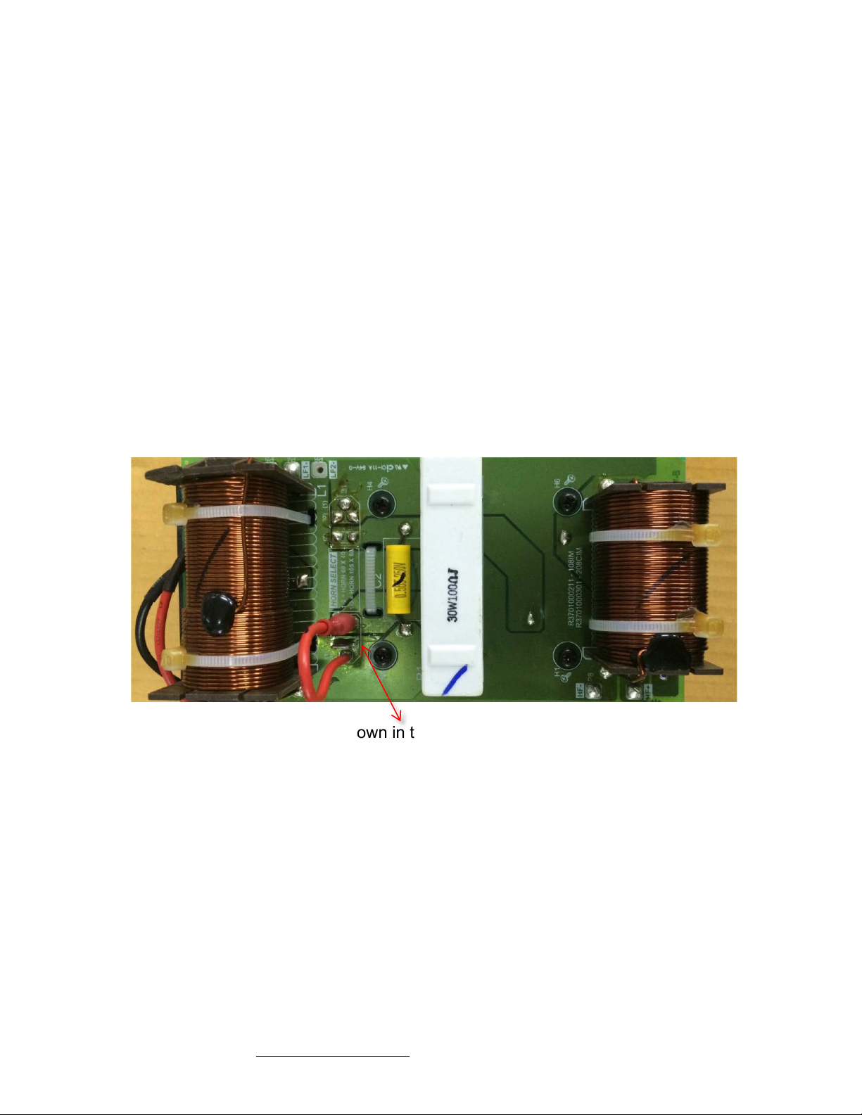
(factory-installed) and the ETS-105/60. There is one jumper on the 108.HTH crossover’s
printed circuit board. This jumper must be removed when the high frequency horn is changed. "
Please see the picture below. This illustrated the side of the printed circuit board that is seen
when the high frequency horn is removed. This can be seen by looking through the hole in the
108.HTH’s enclosure where the horn was mounted. The jumper is shown in the picture below. "
When the ETS-60/40 horn is used, the jumper must be moved so that the jumper makes
connection from position 1 to position 2. When the ETS-105/60 horn is used, the jumper must
be configured so that it makes connection from position 1 to position 3 on the printed circuit
board.
One Systems, Inc.## www.onesystems.com tel:+1-615-823-1655 fax: +1-615-261-1429
One Systems, Inc © 2020, All Rights Reserved
When the ETS-60/40 horn is used, the jumper must be moved so that the jumper makes
connection from position 1 to position 2. When the ETS-105/60 horn is used, the jumper must
be configured so that it makes connection from position 1 to position 3 on the printed circuit
board. "
# 7. Once the jumper has ben configured for the desired high frequency horn, the wires # #
# from the printed circuit board to the compression drive should be reconnected, # #
# making sure that you have observed the correct polarity as noted below. "
NOTE: The wiring for the ETS-60/40 requires the orange wire to be on the positive terminal of
the compression driver and the yellow wire to be on the negative terminal.
Page 3

"
When the ETS-105/60 horn is used, the wiring must be reversed. (The orange wire must be on
the negative terminal and the yellow wire must be on the positive terminal). "
The reverse polarity wiring for the ETS-105/60 is required to offset the signal delay associated
with the shorter horn. This polarity reversal maintains comparable signal delay between the
high frequency horn and the woofer. "
# 8. The fully-wired high frequency horn / driver assembly should now be mounted back ##
# inside the 108.HTH’s enclosure. It is important to insure the desired horizontal and # #
# vertical included angles of the horn be oriented relative to the enclosure. (This ## #
# orientation will be determined by the required radiation pattern and the orientation of #
# the enclosure relative to the acoustic space). Securely tighten the bolts that hold the ##
# horn / driver assembly in the 108.HTH, but do not over tighten them. "
# 9. Replace the 108.HTH’s grille assembly."
NOTE: The image below shows the ETS-105/60 horn oriented with the 105-degree included
angle in the horizontal plane and and the ETS-60/40 horn with the 60-degree included angle in
the horizontal plane.
One Systems, Inc.## www.onesystems.com tel:+1-615-823-1655 fax: +1-615-261-1429
One Systems, Inc © 2020, All Rights Reserved
 Loading...