

Page 1
OneSpace is a Trademark of Comfort Products, Inc.
™
ASSEMBLY INSTRUCTIONS
MODEL 60-5902
SUPPLIER CODE: BJTJ
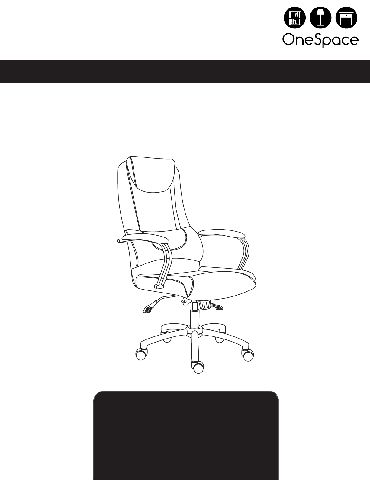
HIGH BACK EXECUTIVE MESH CHAIR WITH HEAD AND
LUMBAR SUPPORT
CUSTOMER SERVICE
replacement parts, or questions please visit our website at
www.comfortproducts.net/support
e-mail: [email protected]
Keep your sales receipt as documentation of your ownership.
For fastest service on claims, request for
Page 2

CONTENTS
ITEMS ARE NOT SHOWN TO SCALE.
PARTS LIST
PART DESCRIPTION STOCK# QTY.
Back Cushion 61-5902BC 1
(1)
(2)
(3)
(4)
(5)
Seat Cushion
Armrest (right)
Armrest (left)
Seat Plate
Seat Post
61-5902SC
61-5902RA
61-5902LA
61-59012SP
61-5902PO
HARDWARE KIT
STOCK # 61-5902HA
.
PART DESCRIPTION QTY.
A 5/16” x 7/8”
5/16” x 1-1/4”
B
M8 x 60MM
C
M8 x 75MM
1
1
1
1
1
E
hcnerW nellA
4
4
2
2D
1
(6)
(7)
Star Base
Caster
61-59012SB
61-5902CA
1
5
REPLACEMENT PARTS
IF YOU ARE MISSING ANY OF THE PARTS ABOVE, OR IF YOU HAVE A DAMAGED PART, PLEASE VISIT
WWW.COMFORTPRODUCTS.NET/SUPPORT AND REFERENCE THE MODEL NUMBER ON THE FRONT OF
THIS MANUAL. SIMPLY COMPLETE THE INFORMATION, INCLUDING THE PART YOU NEED. THE PART
WILL NORMALLY BE SHIPPED WITHIN 48 HOURS.
2
Page 3
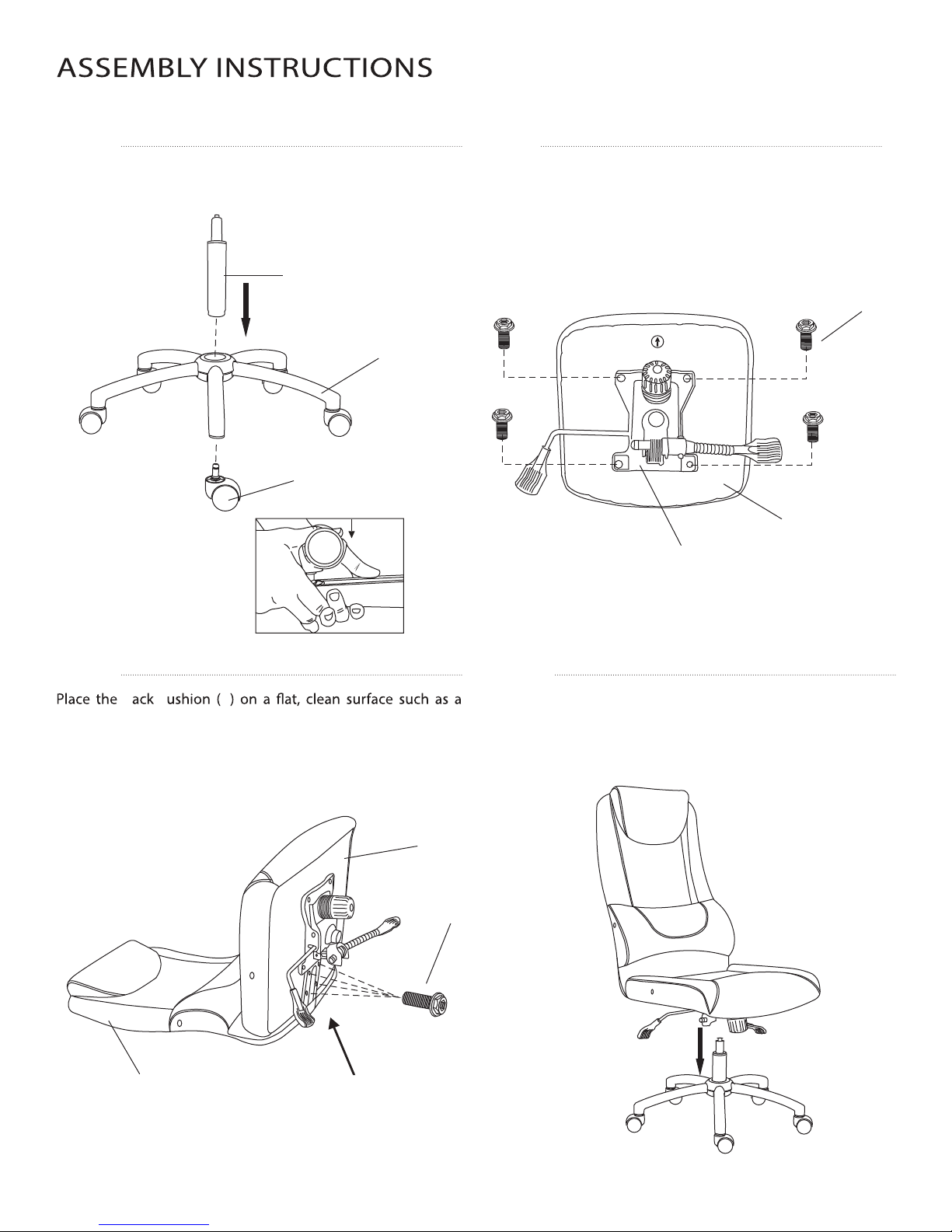
DO NOT TIGHTEN SCREWS UNTIL COMPLETELY ASSEMBLED
STEP 2STEP 1
Insert the casters (7) into the holes of the star base (6). Insert
the gas lift (5) into the center hole of the star base (6).
Align the seat plate (4) over the pre-drilled holes under the Seat
Cushion (2). (NOTE the position of seat plate handle to seat cushion
FRONT). Attach the seat plate (4) to the Seat Cushion (2) using
four scre
Wrench (E).
5
6
7
w
s (A) as shown. Tight
en
securely with the Allen
2
A
NOTE: To install casters, apply
pressure to base of caster
using your thumb as shown
STEP 3
CB
table. Position the Seat Cushion (2) as shown and align the
four holes on the seat cushion with the four holes on the steel
plate of the back cushion. Use four screws (B) to connect them
as below. Do not fully tighten until after armrests are attached.
1 Turn the assembled chair frame upright. Position the center
2
B
STEP 4
hole in the Seat Plate (
lower the chair onto the post.
4
) over the Seat Post (5). Then carefully
4
1
Steel plate of
the back cushion
3
Page 4
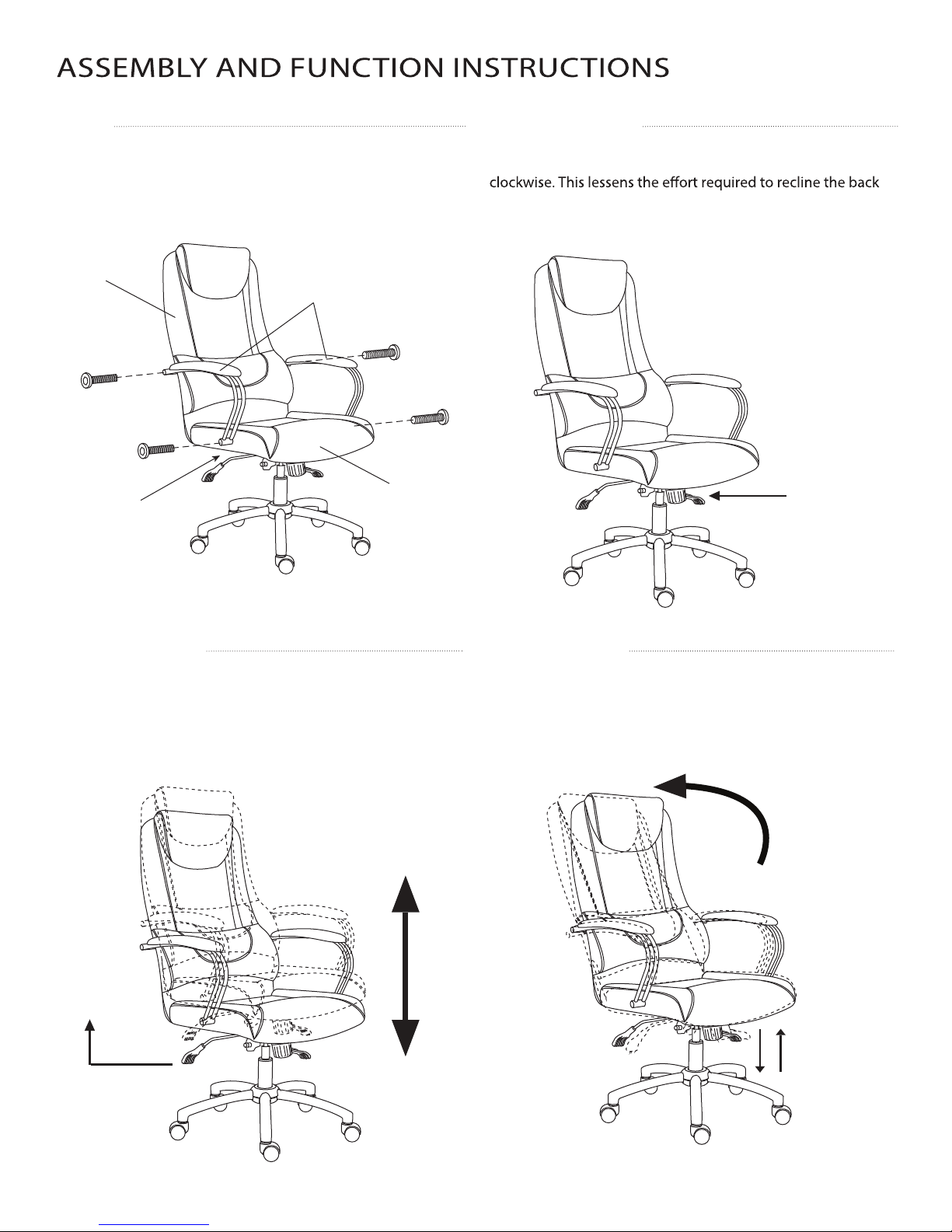
STEP 5
Attach the Left Armrest (3) to the Seat Cushion (2) using
screw (C) and to the Back Cushion (1) using screw (D). Repeat
for the Right Armrest (3). After the armrests are rmly attached,
fully tighten the screws (B) from step 3.
TO ADJUST TILT TENSION
Reach under the front center of the seat and grasp the round
black tension knob. To loosen the tilt mechanism, turn the knob
cushion of the chair. To tighten the tension knob, rotate
counter-clockwise. Rotate the knob until the desired resistance
is reached.
1
3
D
D
C
C
2
Fully tighten
B screws.
TO ADJUST SEAT HEIGHT
While seated, lean forward, lifting your body weight from the
seat. Reach underneath the right side of the chair and locate the
right handle. Pull the handle up slowly to allow the chair to rise
to the desired height. To lower the seat height, pull the handle
up while seated.
Round tension
knob
TO OPERATE TILT LOCK
While seated, reach underneath the left side of the chair to
operate the tilt lock. With the handle in the up position the
chair will tilt. Push the handle down to lock the tilt at the
desired angle.
Right
Handle
Left handle
44
Page 5
FREQUENTLY ASKED QUESTIONS
• WHERE DO I FIND THE MODEL NUMBER AND SUPPLIER CODE FOR MY CHAIR?
The chair model number and supplier code is located on a sticker underneath the seat cushion, and on the front page of your instruction manual.
• HOW DO I ORDER REPLACEMENT PARTS? WHEN AM I GOING TO RECEIVE THEM?
covered under warranty, there is no charge for replacement parts. We normally ship replacement parts within 48 hours.
• HOW DO I ADJUST THE SEAT HEIGHT?
Refer to page 4. While seated, lean forward, lifting your body weight from the seat. Reach underneath the right side of chair and locate the handle.
Lift the handle up slowly with a clockwise twisting motion to allow the chair to rise to the desired height. To lower seat height, lift the handle slowly
with a clockwise twisting motion while seated.
•
Refer to page 4. While seated, reach underneath the right side of chair and locate the handle. Slide the handle all the way out towards the right
(away from the seat). When the handle is in this position, leaning back will cause the chair to tilt backwards. To lock the chair in the upright
(vertical) position, sit in the chair, and push the handle in to the left (towards center of seat). If your chair tilts forward instead of backward, then
you may have the seat plate on backward.
• HOW SHOULD THE CHAIR BE CLEANED?
While we do not recommend a particular brand of cleaning product, you can use a damp cloth to wipe down your chair. Or you can use an overthe-counter cleaner made for the bonded leather upholstery on your chair. If you would like to use a cleaning product, we suggest that you test
Please note that any type of discoloration or alteration made to the chair from a cleaner will automatically void the warranty.
• THE CASTERS ARE DIFFICULT TO INSTALL. HOW DO I INSTALL THE CASTERS?
Refer to inset image on page 3, STEP 1. The metal stem needs to be fully inserted into the bottom of the star base in order for the caster to stay
in. There are 2 options. One: lay the base on the carpeted ground, with the bottom of the base facing upward. Insert each caster into the hole by
applying pressure with your thumb at the base of caster. They should pop in easily. Two: hold the 5-star base in an upright position (One leg is on
push the caster in with a little force, (twisting or using a soft mallet to tap in).
• MY CASTER BROKE. HOW DO I REMOVE THE METAL STEM FROM THE BASE?
You can use pliers to remove the metal pin. Please contact www.comfortproducts.net/support and request a 61-5902CA replacement caster.
•
Make sure all screws are properly tightened, especially the screws attaching the seat plate to the seat cushion. If this does not solve the problem, you
may need a new seat plate (61-59012SP), and gas lift (61-5902PO) for your chair. Please contact us at www.comfortproducts.net/support, or
[email protected].
•
Refer to question above, “How do I adjust the seat height?” If the seat will not maintain its height, order a new gas lift and seat plate at www.comfortproducts.
• HOW DO I REMOVE/REPLACE THE SEAT PLATE AND/OR GAS LIFT?
Refer to page 7 for images and links to video demonstrations. To remove the seat plate from the gas lift: you will need to turn your chair over. Next, get a
rubber mallet. You will want to hit around the area that the gas lift (Cylinder) goes inside the seat plate (The black metal plate attached to the seat that has
a handle). After you hit the seat plate, give the gas lift a pull and see if it is coming loose. These two items are locked together by pressure; the more you
(61-59012SP).(61-5902PO)
chair upside down. There are about one to two inches where the gas lift (Cylinder) goes through the 5 star base (The legs with wheels). Next, grab a rubber
mallet. Then, if you look in the center of the gas lift, there is a little clip. You do not want to hit the clip in the middle as it will release the pressure needed in
order to raise or lower your chair. You will want to hit the outer edge or the rim of the gas lift. The more you hit the gas lift the more pressure will be released.
After you give the gas lifts a few hits, it should come right out, or give it a pull and see if its loose. If it still won’t budge, then visit www.comfortproducts.net/
support or e-mail us at [email protected] to order a new seat plate and gas lift.
• HOW DO I REMOVE/REPLACE THE BASE FROM THE GAS LIFT?
and hammer the post from the underside of the base. If you are still unable to disengage the base, contact us at www.comfortproducts.net/
support.
• HOW DO I REMOVE THE SCREWCAPS FROM MY ARMRESTS?
will help to pry the screwcap loose from the armrest.
ge of the screwcap. This
• THE ARMRESTS SEEM LOOSE. HOW CAN I FIX THEM?
Make sure all screws are properly tightened.
• THE PARTS DON’T SEEM TO ALIGN. WHAT SHOULD I DO?
Do not tighten the hardware completely into the component you are assembling. Tighten hardware a quarter of the way. When all components are
, and the product is at sitting level
aligned , then you can tighten all the screws.
• THE SCREWS WON’ T THREAD INTO THE HOLES. WHAT SHOULD I DO?
Be certain that you are aligned with the hole. Sometimes holes in soft upholstered areas are deep set, and you may not be making contact with
the female inset for the screw. Also, check that there is no deb
ris on the screw or in the inset for the screw. You can also try the spare screw.
5
Page 6
• WHAT IS THE WARRANTY LENGTH?
register your warranty.
• HOW IS THE WARRANTY VALIDATED?
Your warranty time period is validated by the purchase date on your original purchase receipt. (Please note that the warranty can not be validated
without your original purchase receipt).
• WHAT IS THE WEIGHT LIMIT ON MY CHAIR?
The 60-5902 chair has been tested to meet BIFMA standards, and has a weight limit of up to 250 lbs.
SAFETY AND MAINTENANCE
• DO NOT stand on the chair. DO NOT use the chair as a stepladder.
• Use this product for seating one person at a time.
• DO NOT
• Avoid contact with sharp objects to prevent puncturing the fabric.
• Every 6 months, check all bolts and screws to ensure they are tight.
• To clean, spot clean only using a damp towel and mild cleaner. First test on a small, obscure area of fabric.
• Chair weight limit not to exceed 250 lbs.
LIMITED WARRANTY
PLEASE VISIT WWW.COMFORTPRODUCTS.NET FOR WARRANTY INFORMATION
Comfort Products warrants this product to be free from defects in material and workmanship for 1 year. This warranty is made by
Comfort Products only to the original end-user customer acquiring the product directly from Comfort Products’ authorized dealers
as shown by the original sales receipt. The end-user customer remedy pursuant to this warranty
of parts at Comfort Product
parts to be returned to Comfort Products upon request. Natural markings such as scars, brands, grain, variations, wrinkles, color
variations, etc. will be considered normal characteristics, and not construed as defects. Comfort Products cannot warrant leather
before any warranty work is performed. This warranty shall not apply to any products which must be replaced because of normal
wear and tear, negligence, abuse, or “accident”, shipping damage or product use and installation other than in accordance with
someone other than Comfort Products or because of natural variations over which Comfort Products has no control. When repairing
or replacing a defective product, Comfort Products does not guarantee matching color, grain, texture or dye lots. This warranty
does not cover the cost of transportation or labor. In no event shall Comfort Products be liable in either tort or contract for any loss
or direct, special, incidental, consequential or exemplary damages. This Limited Warranty is NOT applicable to end-user customers
who use Comfort Products for rental purposes. This warranty applies only to end-user customers in the United States. All warranties
support. Comfort Products customer service can be reached via e-mail at [email protected].
MODEL: 60-5902
s’ option within a reasonable amount of time. Comfort Products reserves the right to require damaged
is limited to repair or replacement
250
Comfort Products, Inc.
P.O. Box 999
Memphis, TN 38101
e-mail: [email protected]
www.comfortproducts.net
™
OneSpace is a Trademark of Comfort Products, Inc.
6
Page 7
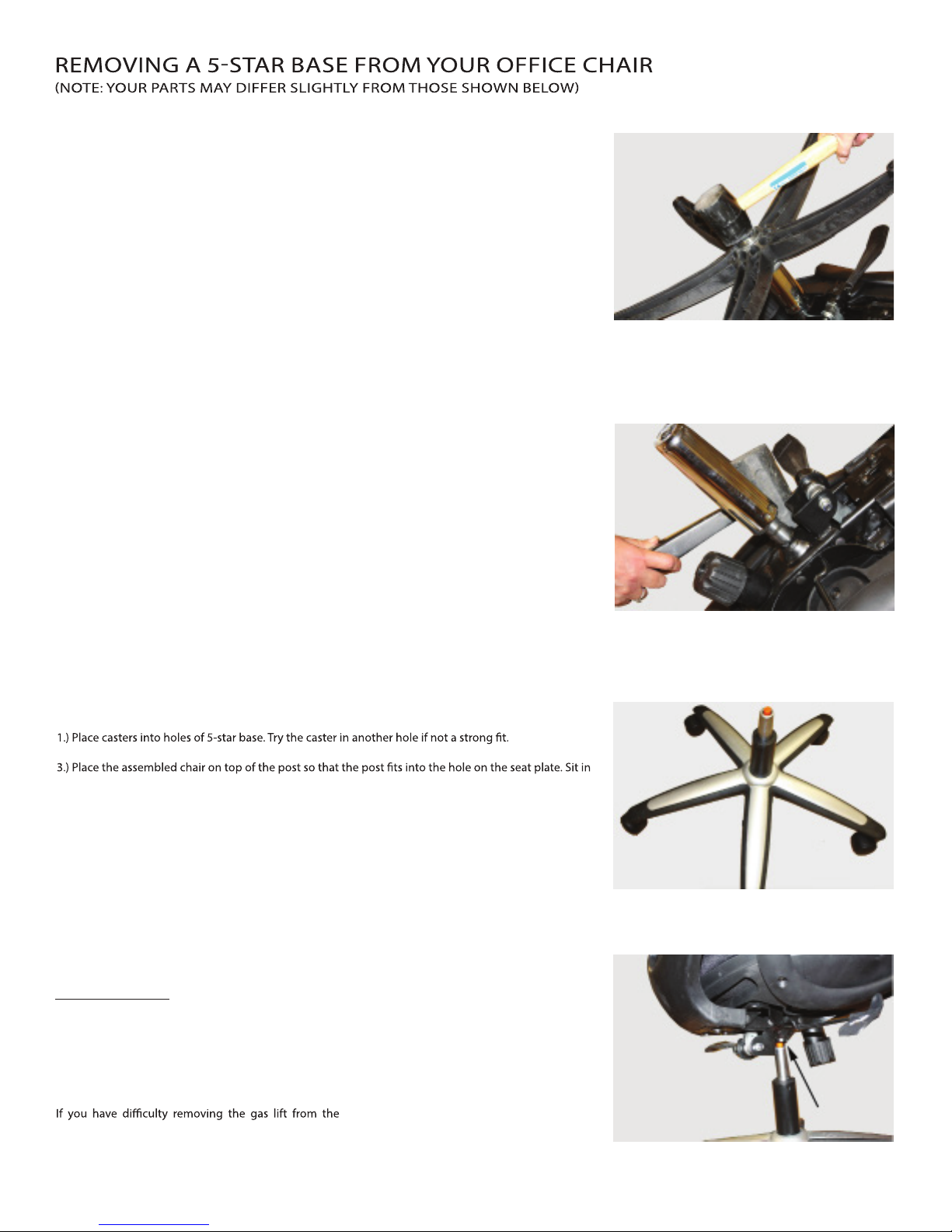
TOOLS NEEDED: (1) Newspaper or cardboard for work area, (2) Silicone lubricant (such as WD40),(3)
Rubber Mallet
INSTRUCTIONS:
1.) Spread newspaper or cardboard on your work surface.
2.) Turn your chair on its side.
3.) Spray lubricant around the center post where connected to your 5-star base.
4.) Remove casters (wheels) from base.
5.) Use the rubber mallet and bang on the center post, directly in the center of the 5-star base (Figure A).
These two parts are engaged by pressure alone. The more you hit it, the more pressure is released, and
eventually the base will release from the post.
FIGURE A
REMOVING A GAS LIFT POST FROM YOUR OFFICE CHAIR
TOOLS NEEDED: (1) Newspaper or cardboard for work area, (2) Silicone lubricant (such as WD40),(3)
Rubber Mallet
INSTRUCTIONS:
1.) Follow instructions for removing 5-star base.
2.) Spray gas lift where connected to seat plate.
3.) With rubber mallet, beat on seat plate around gas lift post to release pressure (Figure B).
The gas lift post is engaged to the seat plate by pressure alone. By banging on the seat plate, you should
be able to reduce the pressure and remove the gas lift.
FIGURE B
REASSEMBLING YOUR OFFICE CHAIR WITH REPLACEMENT PARTS
Tools needed: Newspaper or cardboard for work area.
INSTRUCTIONS:
2.) Position the base on the ground and place the gas lift post into the center hole of the base (Figure C).
the chair to re-engage all parts (Figure D.)
FIGURE C
The colored plastic button should be at the top as
shown.
FIGURE D
VIDEO LINKS
You may visit these websites for a helpful video
demonstration about how to change your gas lift:
http://bit.ly/TvWwot
http://bit.ly/Qic7ox
base, refer to this video link:
http://bit.ly/SPGyyO
7
 Loading...