

Page 1
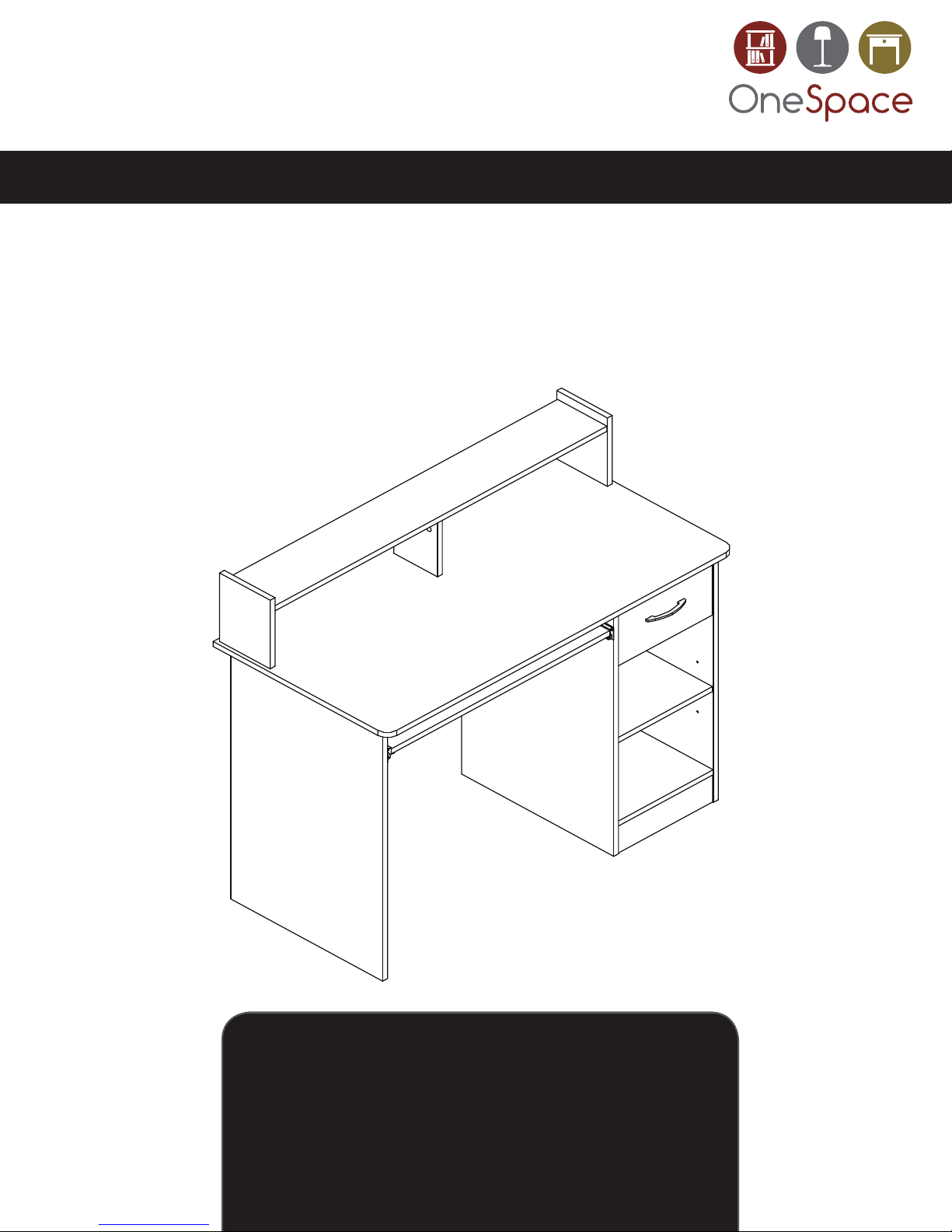
ASSEMBLY INSTRUCTIONS
MODEL # 50-LD0105
SUPPLIER CODE: LDCZ
Essential Computer Desk, Black
™
OneSpace is a Trademark of Comfort Products, Inc.
CUSTOMER SERVICE
For fastest service on claims, request for replacment parts,
www.comfortproducts.net/support
e-mail: [email protected]
Keep your sales receipt as documentation of your ownership.
or questions, please visit our website at:
7
Page 2
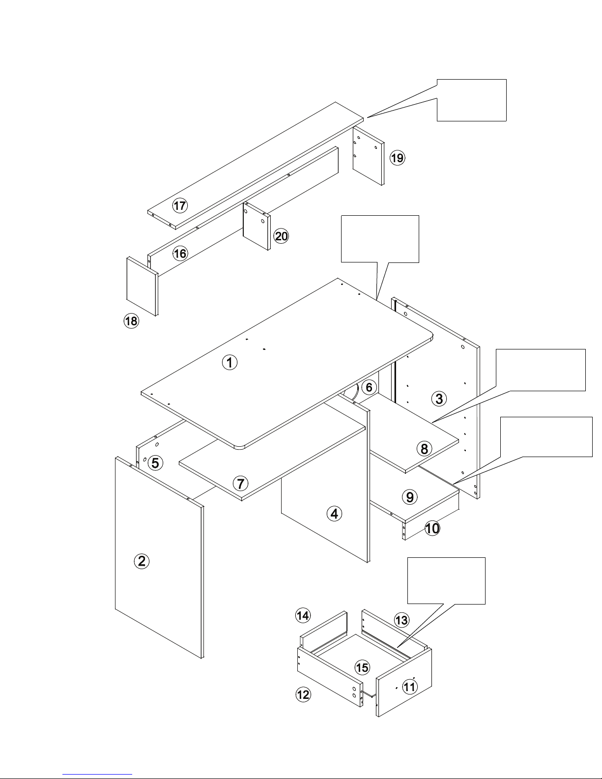
ASSEMBLY OVERVIEW
Hutch maximum
weight capacity
= 22lbs
Desktop maximum
weight capacity
= 165lbs
Drawer maximum
weight capacity
= 11lbs
Middle shelf maximum
weight capacity
= 22lbs
Bottom shelf maximum
weight capacity
= 44lbs
2 of 16
Page 3
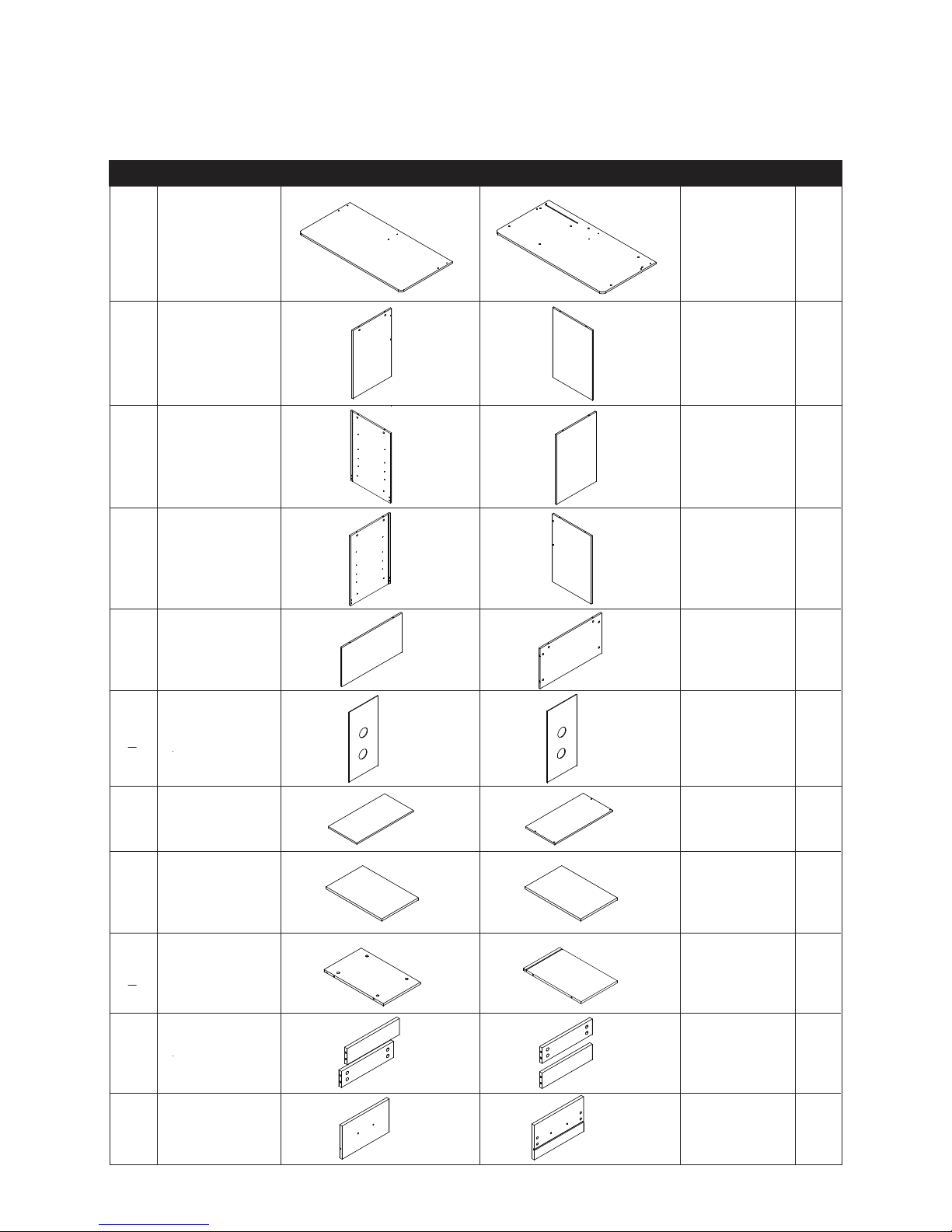
PARTS LIST 1 OF 2
#
DESCRIPTION
SIDE 1 SIDE 2
STOCK #
QTY.
ITEMS ARE NOT SHOWN TO SCALE.
1
Desktop
2
Left Board
3
Right Board
Middle Board
4
5
Left Back Board
Right Back
6
Board
7
Keyboard Tray
8
Middle Shelf
51-LD0105DT
51-LD0105LB
51-LD0105RB
51-LD0105MB
51-LD0105LBB
51-LD0105RBB
51-LD0105KT
51-LD0105MS
1
1
1
1
1
1
1
1
10
11
9
Bottom Shelf
Support Board
Drawer Front
3 of 16
51-LD0105BS
51-LD0105SPB
51-LD0105DF
1
2
1
Page 4
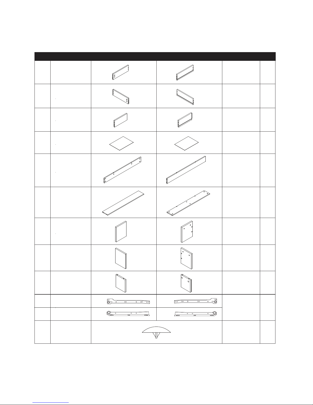
PARTS LIST 2 OF 2
#
DESCRIPTION
SIDE 1
SIDE 2
STOCK #
QTY.
ITEMS ARE NOT SHOWN TO SCALE.
Left Drawer
12
Board
Right Drawer
13
Board
14
Drawer Back
15
Drawer Bottom
16
Hutch Back
Hutch Top
17
51-LD0105LDB
51-LD0105RDB
51-LD0105DB
51-LD0105DBM
51-LD0105HB
51-LD0105HT
1
1
1
1
1
1
18
Hutch Left
19
Hutch Right
20 Hutch Middle
21a
Outer Drawer Rollers
21b Inner Drawer Rollers
Left Right
Left Right
22 Plastic Cap
4 of 16
51-LD0105HL
51-LD0105HR
51-LD0105HM
51-LD0105DS
51-LD0105CA
1
1
1
2 sets
of 4
14
Page 5
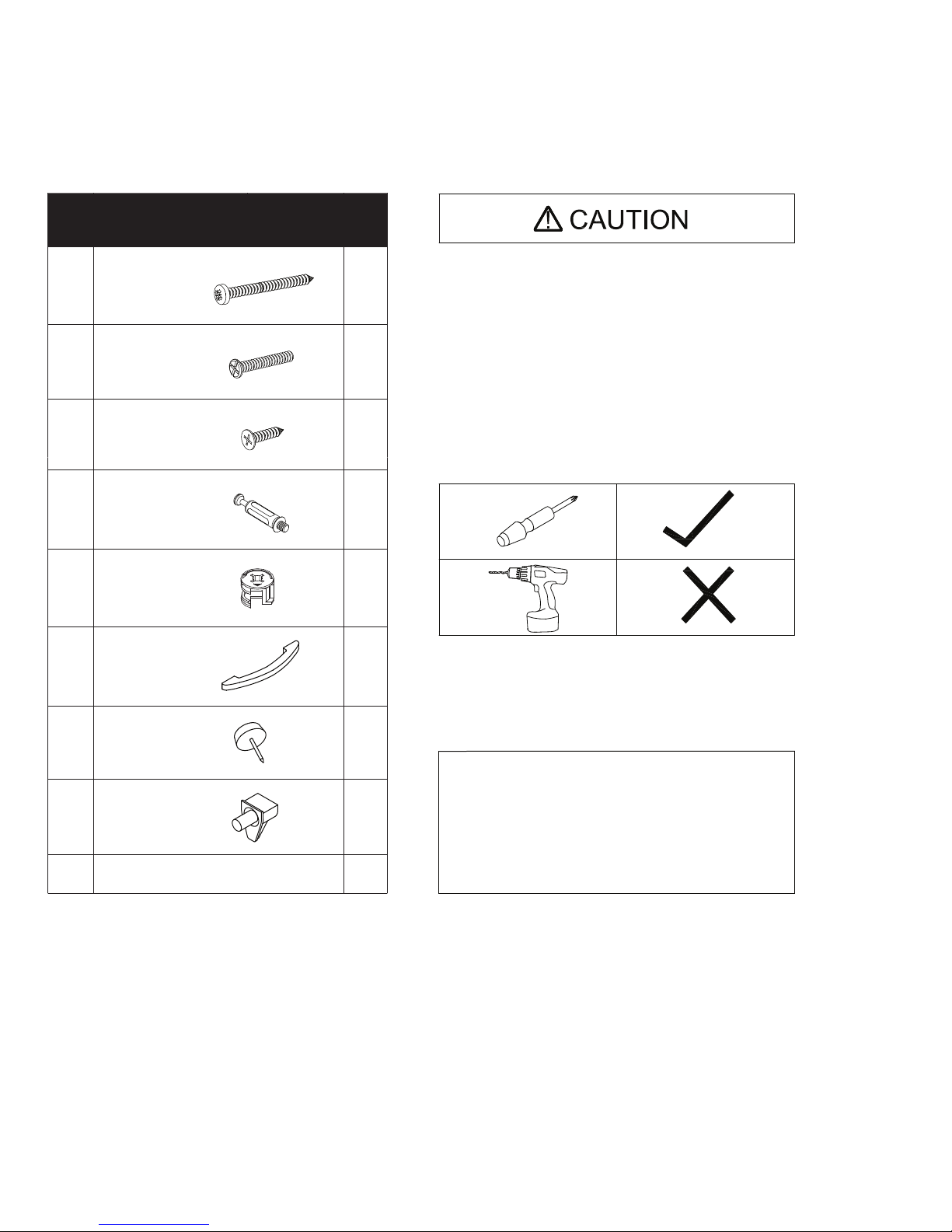
HARDWARE LIST
EXTRA HARDWARE INCLUDED FOR YOUR CONVENIENCE. ITEMS ARE NOT SHOWN TO SCALE.
HARDWARE KIT
STOCK # 51-LD0105HA
PART DESCRIPTION
A M4 X 40MM
M4 X 18MM 2
B
C M4 X 14MM 16
Minix Bolt
D 40
E
Cam
F
Drawer Handle
QT
10
40
Y.
- READ THE INSTRUCTION MANUAL BEFORE ASSEMBLING.
- REMOVE ALL PIECES BEFORE BEGINNING INSTALLATION.
- OPEN THE HARDWARE AS NEEDED .
- ASSEMBLE IN AN AREA WITH PLENTY OF SPACE.
- READ EACH STEP BEFORE BEGINNING CONSTRUCTION.
- NEVER FORCE THE SCREWS OR FITTINGS.
- KEEP THIS MANUAL FOR FUTURE REFERENCE.
- TIGHTEN ALL THE SCREWS EVERY 6 MONTHS.
- HAVE A SCREWDRIVER BEFORE YOU BEGIN ASSEMBLING
(NOT INCLUDED).
- DO NOT USE A POWER DRILL.
1
CLEANING AND CARE
- CLEAN SURFACES WITH A DRY OR DAMP CLOTH.
- DO NOT USE ABRASIVE CLEANERS.
G
Foot Pin
H
Shelf Support
Extra Hardware 1 set
6
IF YOU ARE MISSING ANY OF THESE PARTS,
OR IF YOU HAVE A DAMAGED PART, PLEASE
VISIT WWW.COMFORTPRODUCTS.NET/SUPPORT
4
REFERENCE THE MODEL # ON THE FRONT OF
THIS MANUAL. SIMPLY COMPLETE THE INFORMATION,
INCLUDING THE PART YOU NEED. THE PART WILL
NORMALLY BE SHIPPED WITHIN 48 HOURS.
5 of 16
Page 6

ASSEMBLY INSTRUCTIONS
STEP 1
Use a hammer to attach foot pins (G) to the bottom of the left (2), middle (4), and right (3) boards.
H x 4
6 of 16
Page 7
ASSEMBLY INSTRUCTIONS
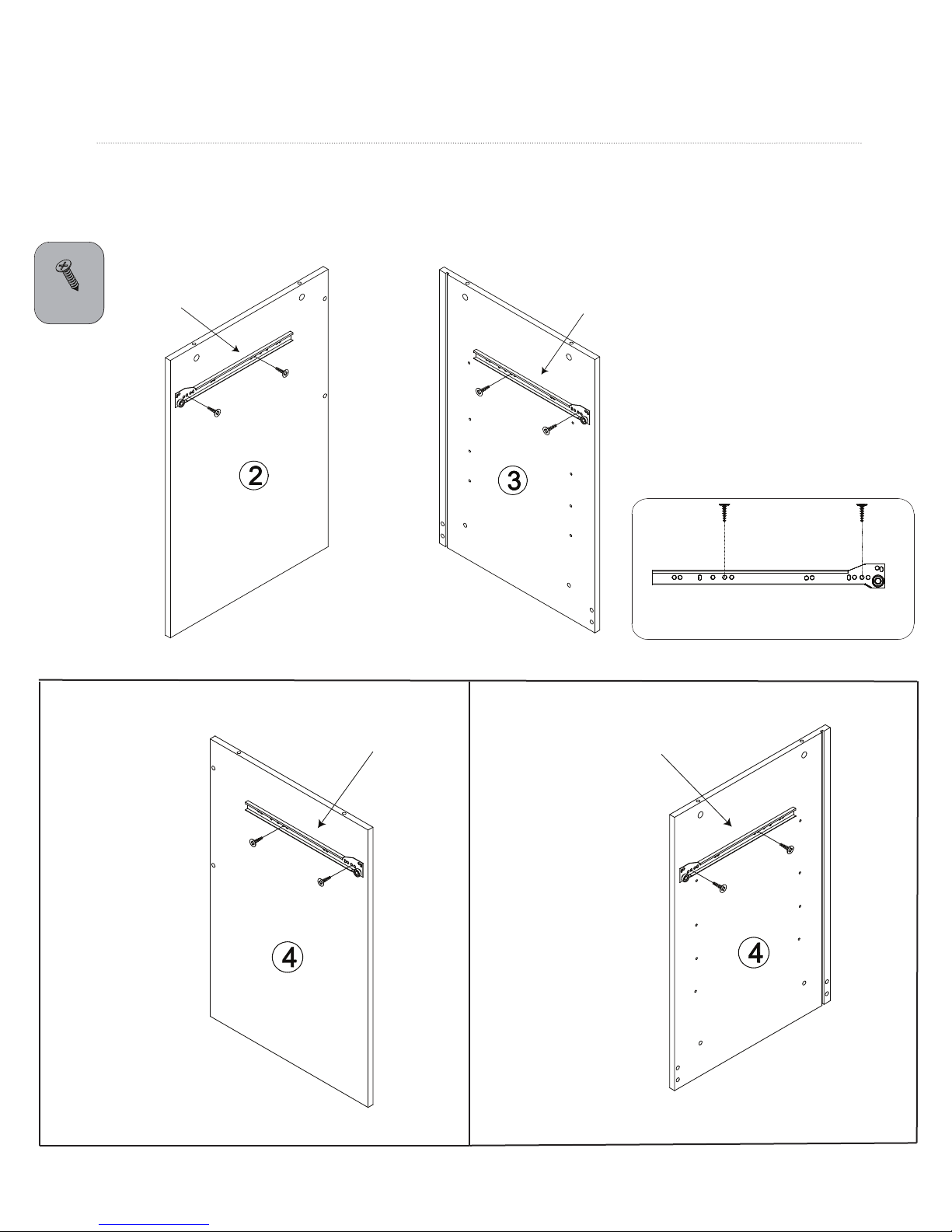
STEP 2
Attach a left outer drawer roller (21a) to the left board (2) and a right outer drawer roller (21a) to the right board (3)
using small screws (C). Attach two rollers to the middle board (4), a right outer roller (21a) to the left side and a
left outer roller (21a) to the right side. Refer to drawing below for which holes in the roller to use.
C x 8
21a, left
21a, right
C
C
C
21a, right
FIFTH TO
LAST HOLE
21a, left
SECOND
HOLE
Left Side
Right Side
7 of 16
Page 8
ASSEMBLY INSTRUCTIONS
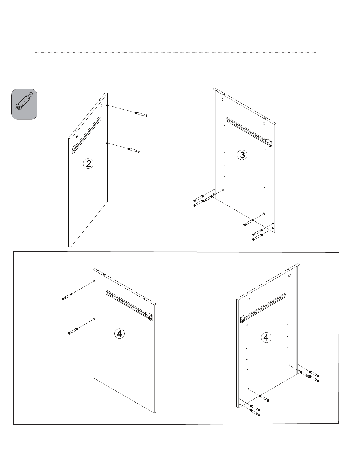
STEP 3
Screw two minix bolts (D) into the left board (2) and six bolts into the right board (3) as shown. Then screw
two minix bolts (D) into the left side of the middle board (4) and six bolts into the right side of the middle board.
Do not overtighten bolts or cams will not lock properly.
D x 16
Left Side
Right Side
8 of 16
Page 9
ASSEMBLY INSTRUCTIONS
STEP 4
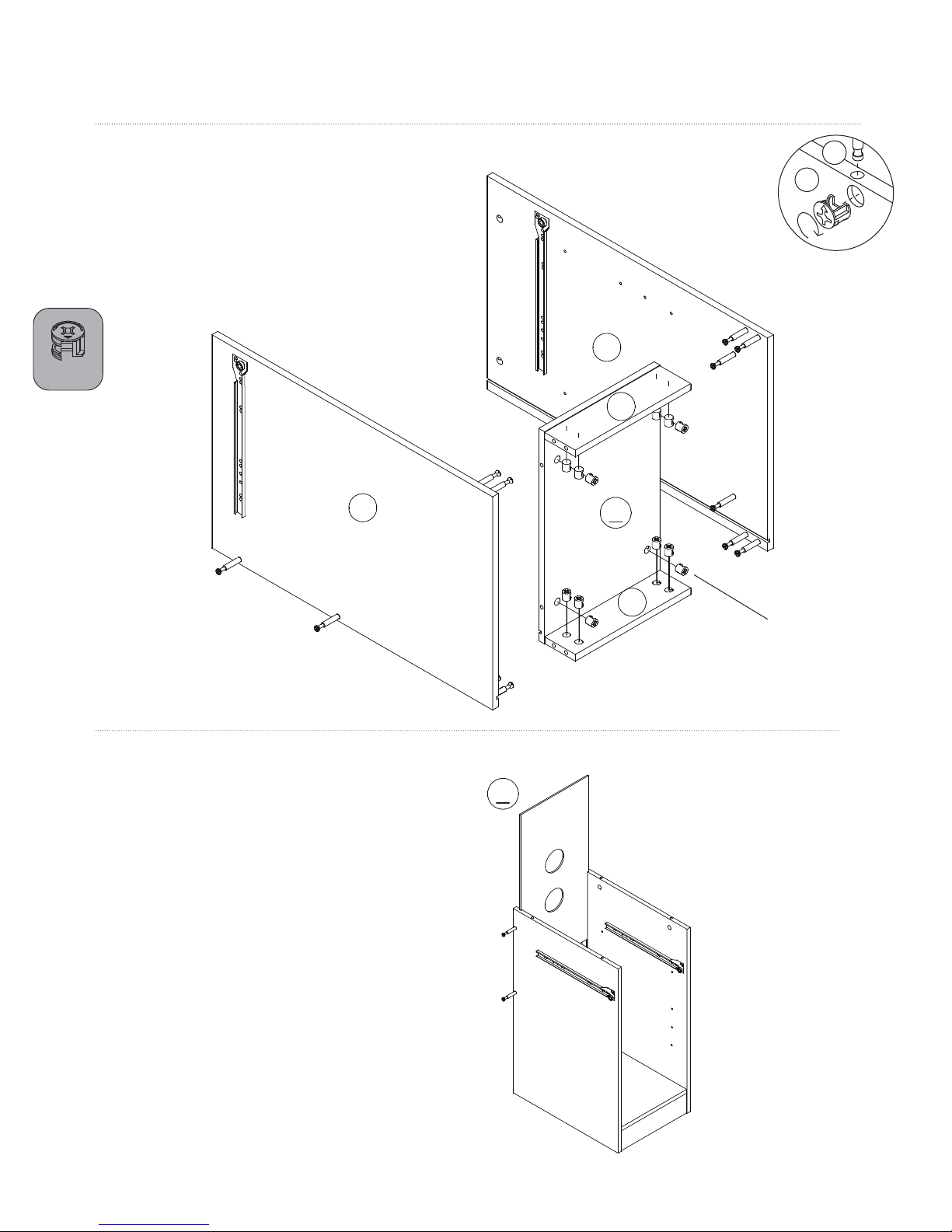
Insert cams (E) into the bottom shelf (9) and into the two
support boards (10). Make sure the arrows are facing the
smaller holes which the bolts go into. First, attach shelf and
support boards to the middle board (4), and then attach
these to the right board (3) by aligning the bolts and cams.
With a screwdriver turn the cams about 1/2 turn clockwise
to lock into place. CAUTION: Do not overtighten cams.
E x 12
4
D
E
CAUTION:
Do not over tighten
cams.
3
10
9
STEP 5
Insert right back board (6) into grooves as shown.
10
E
6
9 of 16
Page 10
ASSEMBLY INSTRUCTIONS
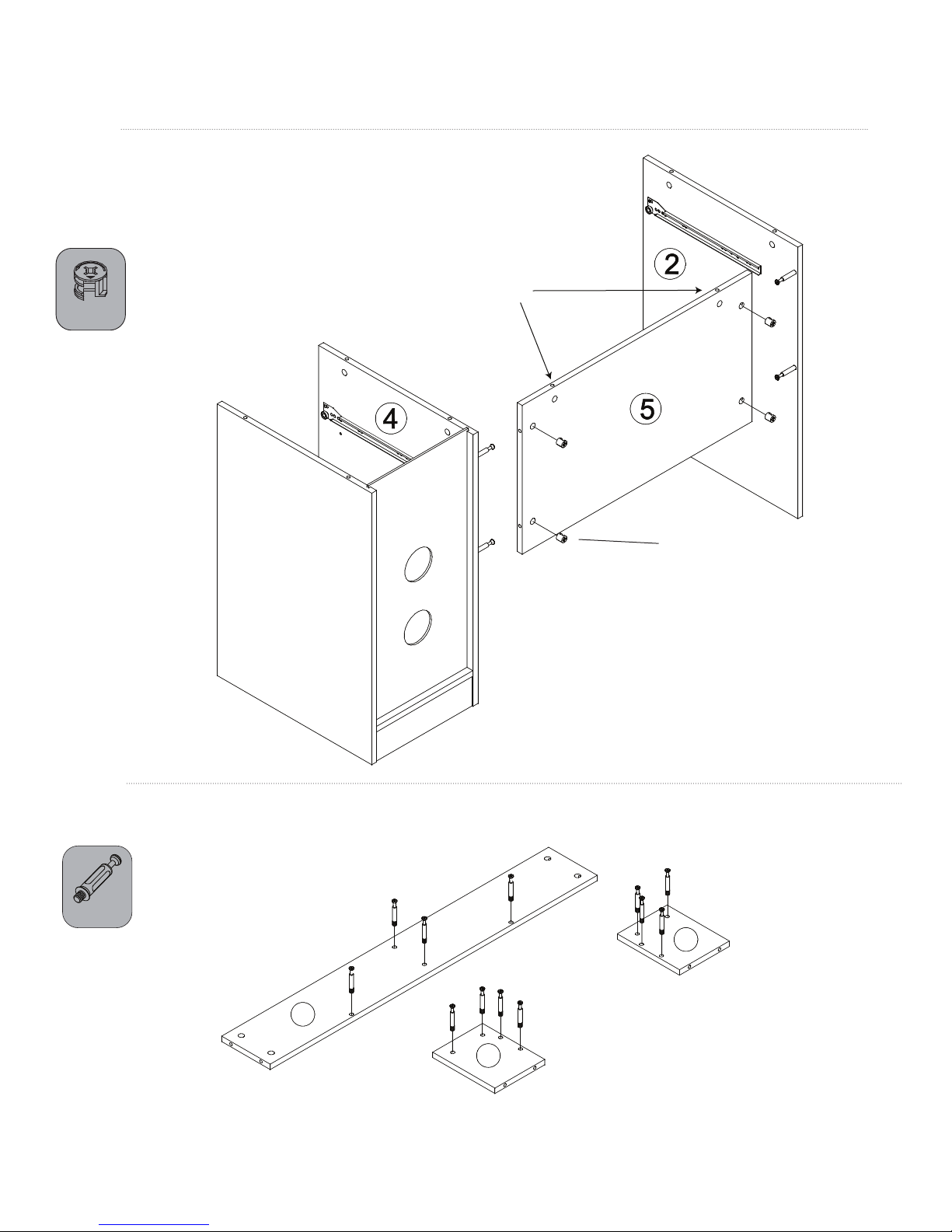
STEP 6
Insert four cams (E) into the left back board (5). Make sure arrows are
facing the smaller holes. Attach back board (5) to left board (2) and
middle board (4). Turn the cams about 1/2 turn clockwise to lock into place.
CAUTION: Do not overtighten cams.
CAUTION: Make sure these
holes are facing up.
E x 4
E
STEP 7
Screw minix bolts (D) into hutch top (17), hutch left board (18), and hutch right board (19).
D x 12
19
17
18
10 of 16
Page 11
ASSEMBLY INSTRUCTIONS
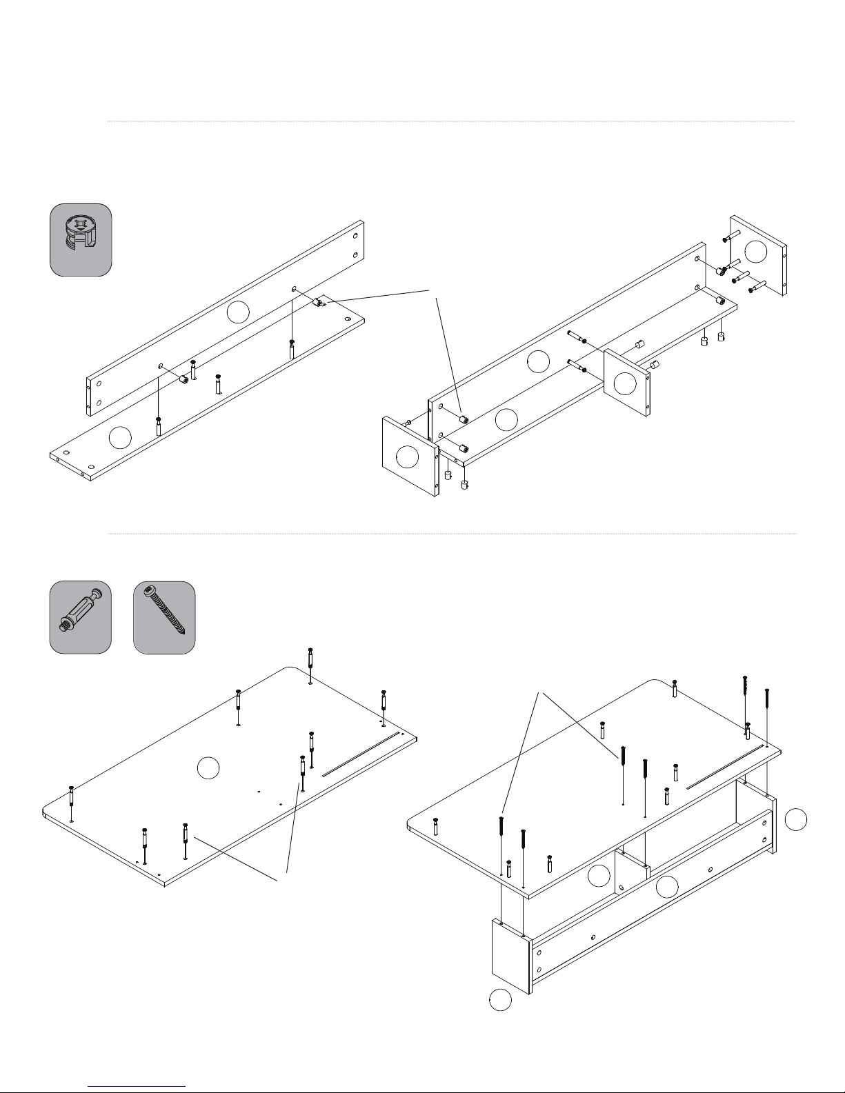
STEP 8
Insert two cams into the hutch back board (16) and attach to the hutch top board (17). Insert ten cams into the
hutch back (16), hutch top (17), and hutch middle board (20). Attach hutch left (18), hutch middle (20), and
hutch right (19) to the back and top boards.
E x 12
E
16
17
20
16
17
18
STEP 9
Screw eight minix bolts (D) into desktop (1). Attach hutch to desktop using six screws (A) as shown.
D x 8
A x 6
19
1
D
A
19
20
16
18
11 of 16
Page 12
ASSEMBLY INSTRUCTIONS
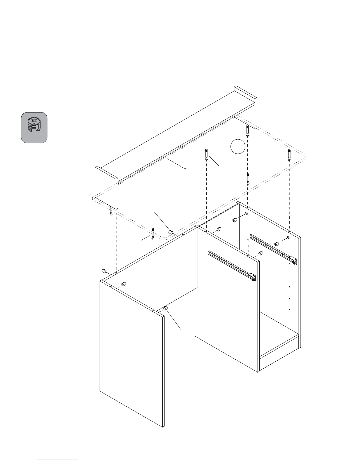
STEP 10
Insert eight cams (E) into the left, middle, and right boards
and left back board as shown. Attach desktop (1) with hutch to
the lower part of the desk by aligning the eight bolts (D)
(already screwed into the desktop) with cams. Tighten
cams 1/2 turn.
E x 8
1
D
E
D
E
12 of 16
Page 13
ASSEMBLY INSTRUCTIONS
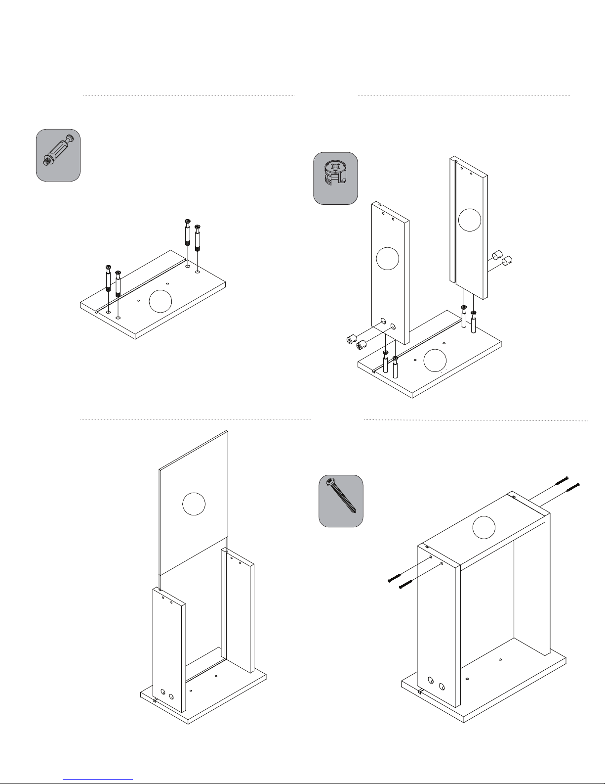
STEP 11
Screw four minix bolts (D) into the drawer front (11).
D x 4
11
STEP 12
Insert cams into the left (12) and right (13) drawer boards
and attach both boards to the drawer front (11). Make
sure the grooves for the drawer bottom are aligned.
E x 4
13
12
11
STEP 13
Insert drawer bottom (15) into
grooves.
STEP 14
Align groove in drawer back (14) with drawer bottom. Attach
drawer back (14) to left and right drawer boards using
four screws (A).
15
A x 4
14
13 of 16
Page 14

ASSEMBLY INSTRUCTIONS
STEP 15
Attach drawer handle (F) to drawer front using
two screws (B).
B x 2
B
F
STEP 16
Attach two inner drawer rollers (21b), one left and one
right, to the bottom of drawer using four screws (C) as shown.
Make sure rollers are oriented to the back of the drawer.
Refer to drawing below for which holes in the roller to use.
21b, left
C x 4
21b, right
STEP 17
Attach two inner drawer rollers (21b), one left and one right,
to the bottom of the keyboard tray (7) using four screws (C).
C x 4
21b, right
7
THIRD TO
LAST HOLE
21b, left
THIRD
HOLE
14 of 16
Page 15
ASSEMBLY INSTRUCTIONS
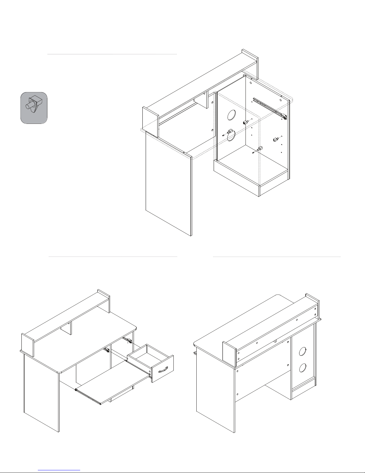
STEP 18
Insert shelf supports (H) into any of the four sets of holes,
according to desired height. Place middle shelf (8)
on supports.
H x 4
STEP 19
Align inner and outer rollers to insert
drawer and keyboard tray.
STEP 20
Place plastic caps (22) over cams at the back of the
desk and cams in the hutch middle board (20).
15 of 16
Page 16
DO NOT stand on the desk. Do not use the desk as a stepladder.
•
•
Every 6 months, check all bolts and screws to ensure they are tight.
•
This product is California 93120 Compliant for Formaldehyde.
•
PLEASE VISIT WWW.COMFORTPRODUCTS.NET FOR WARRANTY INFORMATION
Comfort Products warrants this product to be free from defects in material and workmanship for one (1) year. This warranty is made by
Comfort Products only to the original end-user customer acquiring the product directly from Comfort Products’ authorized dealers
as shown by the original sales receipt. The end-user customer remedy pursuant to this warranty is limited to repair or replacement of
parts at Comfort Products’ option within a reasonable amount of time. Comfort Products reserves the right to require damaged parts
to be returned to Comfort Products upon request. Consent from Comfort Products must be obtained before any warranty work is
performed. This warranty applies under conditions of normal use and is not subject to defects caused by improper assembly or
disassembly; defects occurring after purchase due to product mo
to the elements; labor or assembly cost. This warranty does not cover the cost of transportation or labor. In no event shall Comfort
Products be liable in either tort or contract for any loss or direct, special, incidental, consequential or exemplary damages. This Limited
Warranty is NOT applicable to end-user customers who use Comfort Products for rental purposes. This warranty applies only to end-user
customers in the United States. All warranties are limited to the original purchaser for normal use. The weight capacites are dened as
165 pounds for the desktop, 11 pounds for the drawers, 22 pounds for the middle shelf, 44 pounds for the bottom shelf, and 22 pounds
for the hutch. For claims or questions concerning this warranty, please visit: www.comfortproducts.net or email us at:
[email protected]
MODEL: # 50-LD0105
ed.
sure
Comfort Products, Inc.
P.O. Box 999
Memphis, TN 38101
www.comfortproducts.net
[email protected]
™
OneSpace is a Trademark of Comfort Products, Inc.
16 of 16
 Loading...