

Page 1

User Manual
1
Chapter 1: DVR Features
DVR Features
MPEG4 compression
Video input / output:4-CH video input
1-CH video output
Internet ready
System format: NTSC/PAL
Uses SOC chip with high stability
Linux operation system, stable network performance
Supports multiple recording modes: Continuous, Motion Detection, Time Schedule
Supports event list and search/playback by specified time
Supports hidden channel and playback display
Missing video signal alarm function
Password protection function
Supports IR remote control
Supports SATA hard drive up to 500GB
Page 2
User Manual
2
Chapter 2: Overview
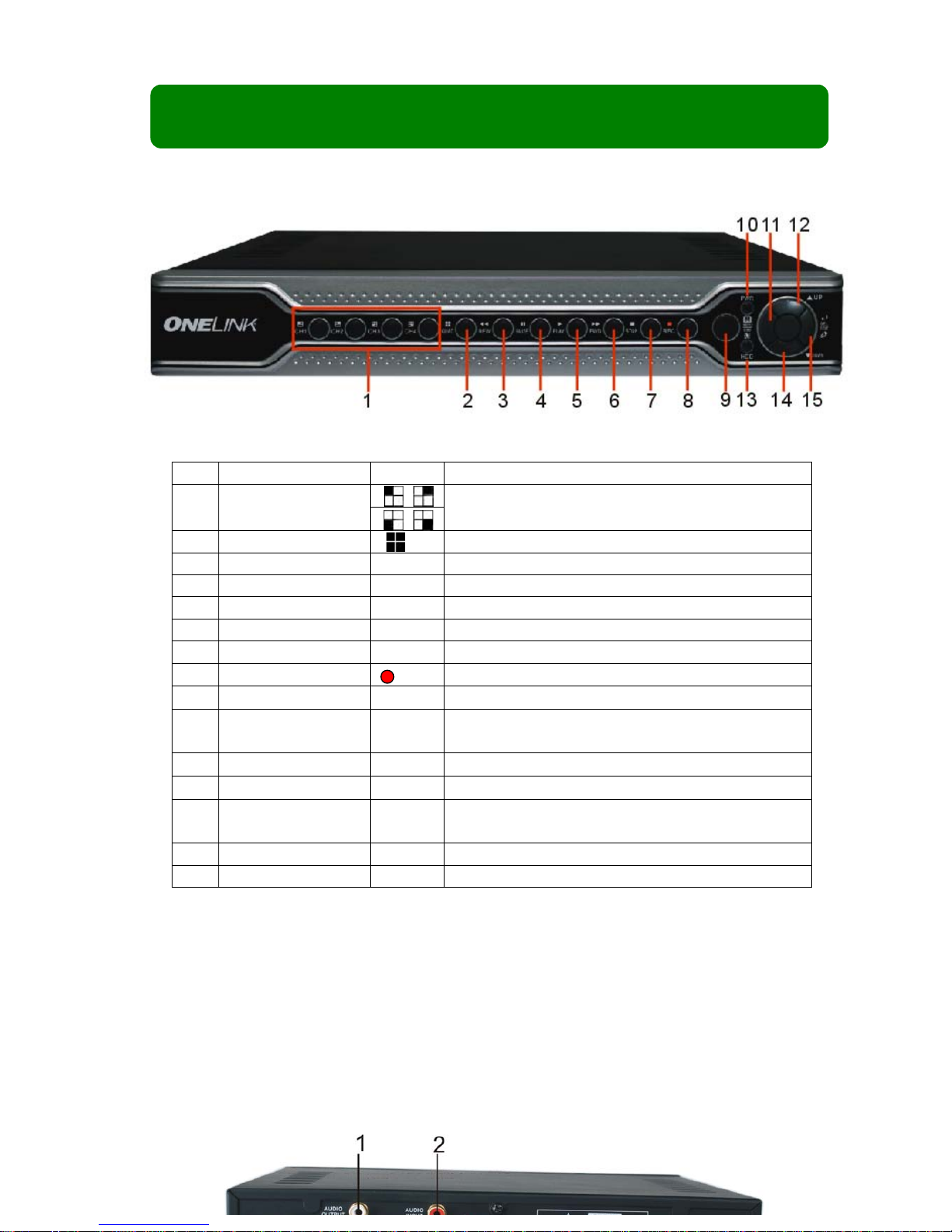
2.1 Front Panel
Item
Key title/Indicator
Marks
Functions
1 Channel Select:
CH1 CH2 CH3 CH4
Select single channel to display
2
QUAD
Display 4 cameras in live display or playback mode
3
REW
Move left / rewind
4
PAUSE
Pause
5
PLAY
Play
6
FWD
Move right / play forward
7
STOP
Stop playback; stop manual recording
8
REC
Start manual recording
9
IR Receiver
Receives signal from remote control
10
Power indicator
PWR
If the “Green” indicator is illuminated, the DVR is
powered on.
11
MENU/ESC
Enter into main menu or exit menu
12
Up Move up
13
HDD indicator
HDD
When the “Red” indicator flashes, it means the hard
drive is being read or written to.
14
Down
Move down
15
SEL/EDIT
Enter into pop up menu; Select key / edit
2.2 Rear Panel
Page 3
User Manual
3
1
Audio output
4
Video output
2
Audio input
5
4 BNC video inputs
3
LAN
6
Power Supply Input
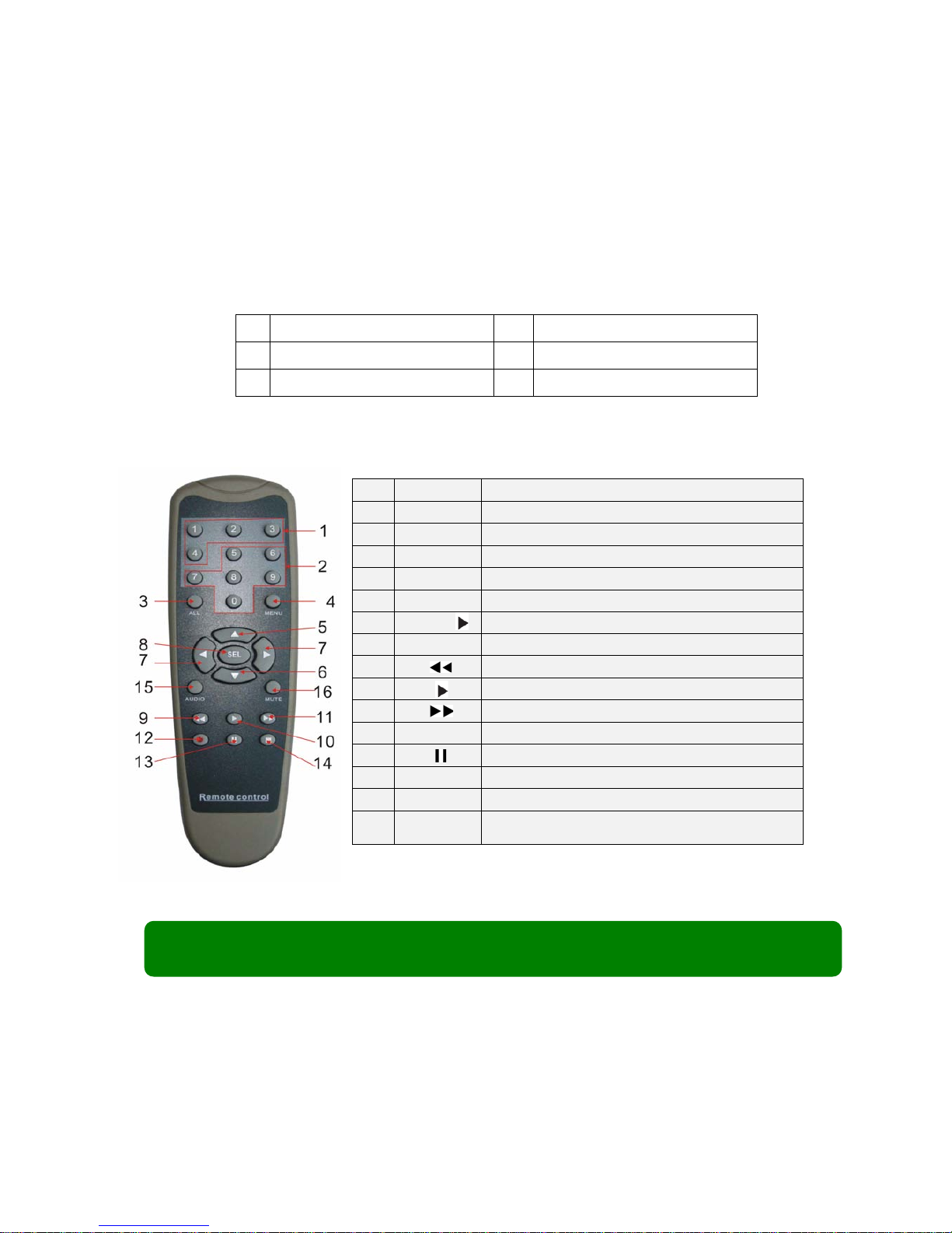
2.3 Remote Control
Chapter3: Installation
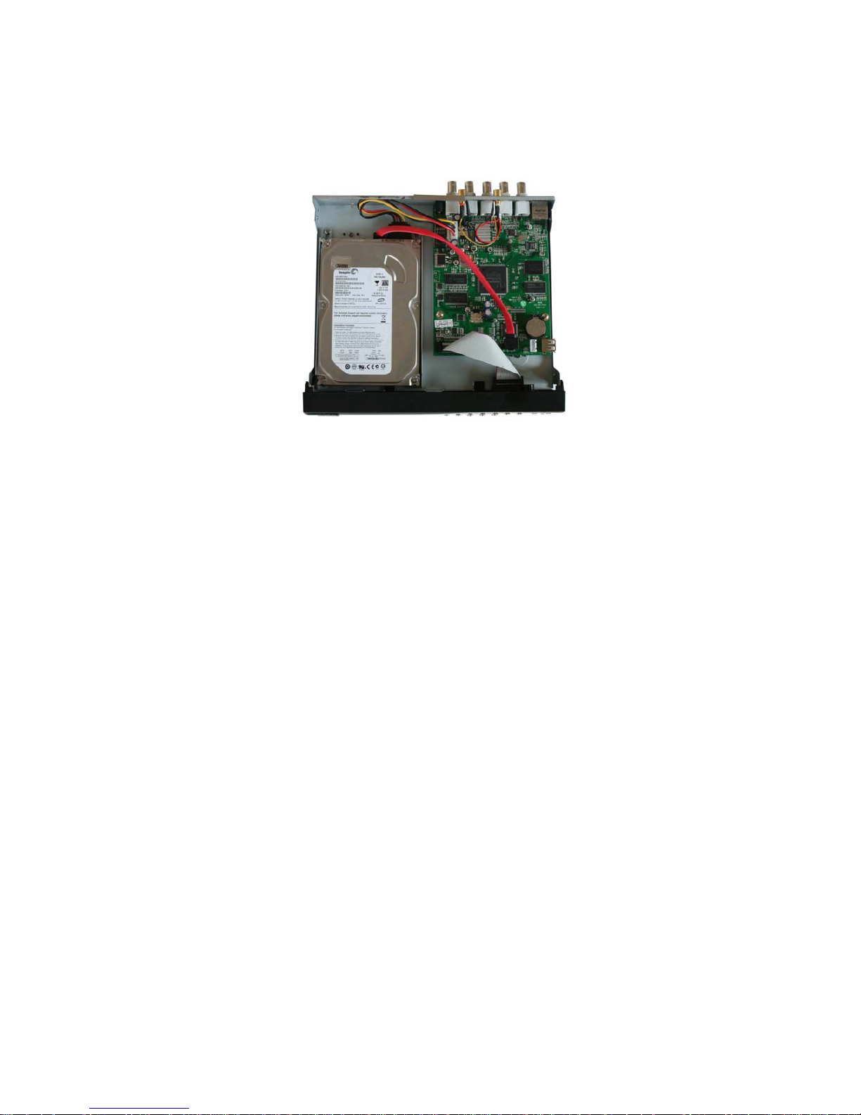
3.1 Installing Hard Drive
(If your DVR comes with a pre-installed hard drive, please ignore this part)
Note: Don’t take out HDD when DVR is running, and make sure the HDD is set as
the MASTER according to the hard drive manual.
1
1-4
Channel Select 1-4
2
5-90
Numeric Key
3
ALL
Preview all Channel
4
Menu
Enter/Exit Main Menu
5 ▲ Up Key
6 ▼ Down Key
7
◄ /
Left / Right Key
8
SEL
Select Key/ Edit Key
9 Rewind key
10 Play Key, Enter to recording search menu
11 Forward Key
12
●
Manual Recording
13 Pause
14 ■ Stop manual recording; Stop Playback
15
Audio
Undefined
16
Mute
Turn on/off audio output
Page 4
User Manual
4
1. Unplug the power supply. Don’t install or uninstall HDD when DVR is running.
2. Remove the DVR cover carefully.
3. Connect the power cord and data cable to HDD.
4. Use the provided screws to fix hard drive on the rack, and then replace the
cover.
3.2 Connecting Camera and Monitor
There are 4 camera inputs and 1 video output with BNC connectors (Refer to the
diagram of the Rear Panel in 2.2.)
3.3 Connecting the Power Supply
Please only use the power adapter supplied with the DVR. The standard power
supplied to the DVR is DC 12 Volt.
Page 5

User Manual
5
Chapter 4: Starting the DVR
4.1 Firmware version
4.2 Detecting Installed Hard Drive
4.3 Format Hard Drive
After turning on the unit, the DVR will boot-up and
display the current version and release date of the
DVR firmware.
V2.X
V-EN-BG
2008.XX.XX
During start up, the DVR will automatically
detect the installed hard drive and show the hard
drive information.
MASTER [MAXTOR STM3250310A]
SLAVE……
When detecting a new hard drive, the DVR will
automatically prompt you if you need to format the
hard drive before recording.
Please press [SEL] to format, or [MENU] to
cancel, and then start the system.
CHECKING HDD……
MASTER [MAXTOR STM3250310A]–NEW–DVR
FORMAT HDD CONFIRM
(SELECT) FORMAT / (MENU) CANCEL?
Page 6
User Manual
6
Chapter 5: DVR Setup
5.1 Browsing the Main Menu
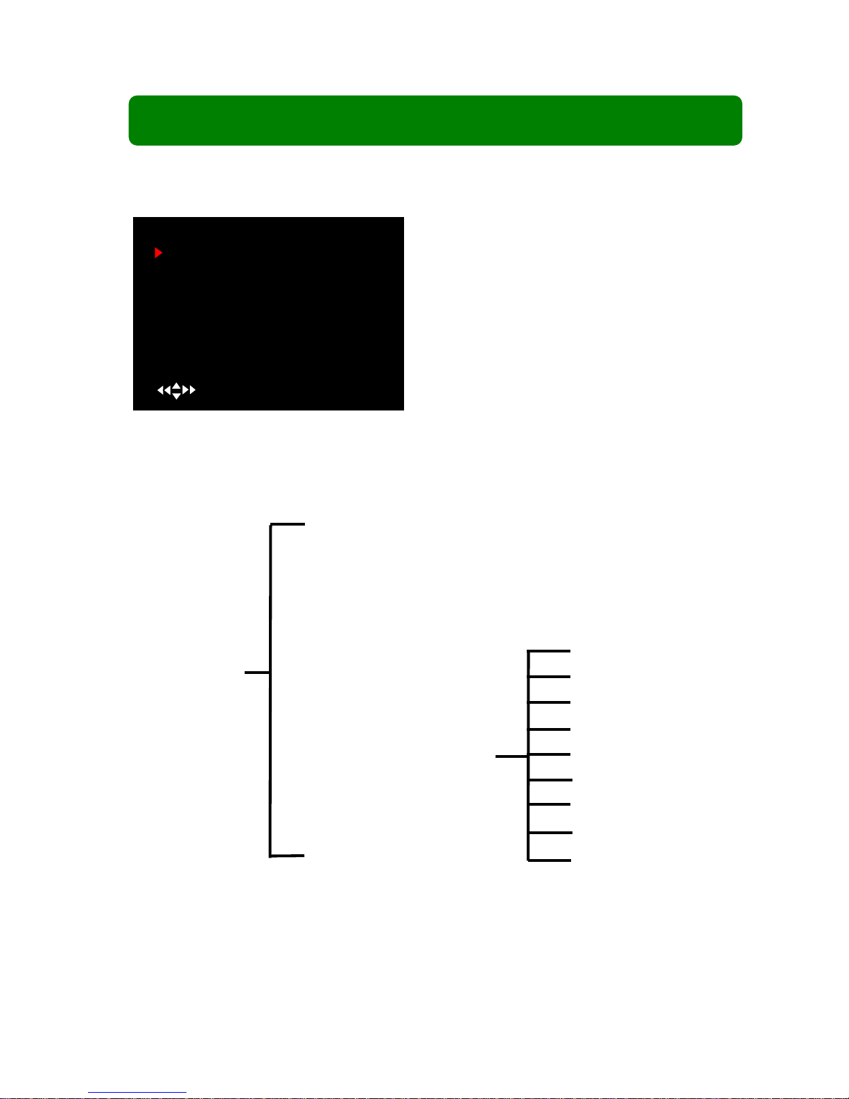
5.2 Menu Directory
Camera Setup
Record Setup
Record Framerate
Video Quality
Record Schedule
Sensor Setup
Hard Drive Setup
Miscellaneous Setup
Network Setup
Language
Reset Menu
When start up is finished, please press [MENU] to
enter the Main Menu.
MAIN MENU
CAMERA SETUP
RECORD SETUP
RECORD FRAMERATE
VIDEO QUALITY HIGH
RECORD SCHEDULE
SENSOR SETUP
HARD DRIVE SETUP
MISCELLANEOUS SETUP
NETWORK SETUP
LANGUAGE ENGLISH
RESET MENU
( ) MOVE (SEL) SELECT (MENU)EXIT
Main Menu
Change Password
Set Time
Hidden Channel
Audio Port Setup
Image Parameters
Password Enable
Keypad Tones
Seq. Dwell Time
VIideo Loss Sound
Page 7

User Manual
7
5.3 Camera Setup
Note: If a channel is disabled in Channel Setup, the DVR will not record or set frame rate.
5.4 Record Setup
5.5 Record Framerate
Press [▲,▼ ,◄◄ and ►► ] buttons to select a channel, and then press [SEL] to increase the
value or press [■STOP] to reduce the value.
Note: Higher frame rate shows smoother video, but requires more hard-drive space.
Camera Setup allows you to turn cameras on
or off.
Press [▲,▼,◄◄ and ►►] buttons to select
a channel, and then press [SEL] to modify the
setting to “on” or “off”.
1 on 2 on
CAMERA SETUP
3 on 4 on
( ) Move (SEL) Select (MENU) EXIT
Record Setup allows you to set up recording
channels. Press [▲,▼,◄◄ and ► ►] to select a
channel, and then press [SEL] to change the setting
to on or off.
If a channel is disabled in Camera Setup, it will
not be recorded, and the characters “NOCAM” will be
displayed on the screen.
1 ON 2 NO
RECORD SETUP
3 ON 4 ON
( ) MOVE (SEL) SELECT (MENU) EXIT
The total frame rate is 50fps (PAL) or 60fps
(NTSC). You can set the frame rate for each channel
to meet your requirements up to the 50fps or 60fps
limit.
1 3 FPS 2 5FPS
RECORD FRAMERATE
TOTAL 36 FPS
3 25FPS 4 3FPS
( ) MOVE (SEL)+ ( ■ )- (MENU) EXIT
Page 8

User Manual
8
5.6 Video Quality
5.7 Record Schedule
Setting the Record Schedule allows you to customize the type of recording you want to use
depending on the time of day.
NO-RECORD [ WHITE ]:DVR will not record during this period.
NORMAL RECORD [ RED]:DVR will record continuously during this period.
SENSOR RECORD [ S ]:DVR will record when sensor or motion is triggered
Note: In order to activate the record schedule, please press [ REC] button to start Record
schedule, otherwise, the DVR will not begin recording.
5.8 Sensor Setup
CONT: Continuous alarm until any key is pressed.
OFF: No alarm
The time line indicates 24 hours of a day based on
AM/PM (0=12).
Press [▲,▼,◄◄ and ►►] buttons to select a
time point, press [SEL] to modify the recording mode.
RECORD SCHEDULE
AM PM
0… 3… 6… 9… 0… 3…. 6… 9…
NO-RECORD
NORMAL-RECORD
SENSOR -RECORD
( ) MOVE (SEL) SELECT (MENU) EXIT
S
Sensor Record Time is no use here as this
model does not support external sensor
inout/output.
Alarm On Time indicates how ndicates how
long the r long the buzzer will sound when motion is
SENSOR SETUP
SENSORED RECORD TIME 30
ALARM ON TIME 05
MOTION DETECTOR SETUP
( ) MOVE (SEL)SELECT (MENU)EXIT
Video Quality has 4 different settings, including:
Highest, High, Normal and Low.
The Higher the video quality, the better the
quality of images, however higher quality images
require more hard drive space.
Press [SEL] button to change the quality setting.
MAIN MENU
CAMERA SETUP
RECORD SETUP
RECORD FRAMERATE
VIDEO QUALITY HIGH
RECORD SCHEDULE
SENSOR SETUP
HARD DRIVE SETUP
MISCELLANEOUS SETUP
NETWORK SETUP
LANGUAGE ENGLISH
RESET MENU
( ) MOVE (SEL) SELECT (MENU) EXIT
Page 9
User Manual
9
Note: Alarm On Time is measured in seconds.
5.9 Motion Detector Setup
This section allows you to set up motion detection options for each camera.
Press the “Stop” button to disable all areas, and press “Quad” button to select all areas.
5.10 Hard Drive Setup
HDD SIZE: indicates the total capacity of the hard drive installed in the DVR.
HDD USED:indicates the space used in the hard disk drive for recording and the percent used.
HDD FORMAT: will erase all video and data on the installed hard drive.
Note: You will be prompted for the password when formatting a hard drive and the default password is
“111111”.
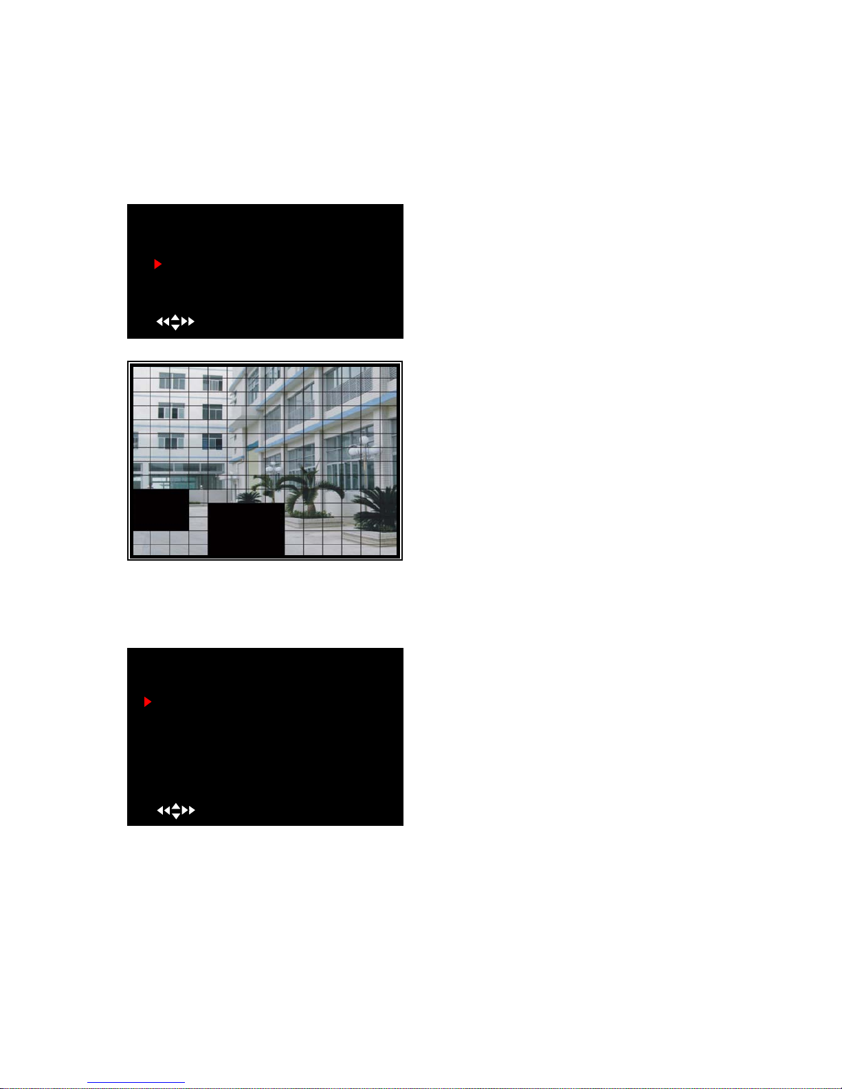
On/off: Enable or disable motion detection
recording.
Level: Sensitivity for motion detection. There
are 3 levels of sensitivity: Level 1 to 3 with 3 being
the highest.
Area: Select detectable area on the screen.
Area Selection:Press [▲,▼,◄◄ and ►►]
buttons to select a block and then press [SEL] button
to set the block to detect motion. The area is
detectable when it is clear, the area is not detectable
when it is covered by a shadow.
OVERWRITE ENABLED:
ON: System overwrites oldest files when hard drive
is full;
OFF: System stops recording when hard drive is full.
HARD DRIVE SETUP
OVERWRITE ENABLED [ON]
MAXTOR STM250310AS
MASTER HDD SIZE 250203MB
MASTER HDD USED 124931MB 50%
MASTER HDD FORMAT
SLAVE HDD SIZE N/A
SLAVE HDD USED N/A
SLAVE HDD FORMAT
( ) MOVE (SEL)SELECT (MENU)EXIT
MOTION DETECTOR SETUP
CH1 ON Level 2 Area
CH2 ON Level 2 Area
CH3 ON Level 2 Area
CH4 ON Level 2 Area
( ) MOVE (SEL)SELECT (MENU)EXIT
Page 10

User Manual
10
5.11 Miscellaneous Setup – Change Password
5.12 Miscellaneous Setup – Set Time
5.13 Miscellaneous Setup – Hidden Channel
The system date and time format is YYYY/MM/DD
and HH:MM:SS.
Press [◄◄] or [► ►] buttons to select a data, press
[SEL] button to modify the data, and press [MENU]
button to save and return to previous menu.
SET TIME
2008/11/11 17:50:01
( ) MOVE (SEL) SELECT (MENU) EXIT
Enter the current password first, and then enter
six characters as your new password, repeat the new
password to confirm.
If you forget your password, please free feel to
contact First Alert Tech Support for assistance.
CURRENT PASSWORD
NEW PASSWORD
COMFIRM PASSWORD
[- - - - -]
[- - - - -]
[- - - - -]
This option allows you to change the system
password. The password must be six characters. All
keys can be used as a password key except the
[MENU] key, which is used to exit.
MISCELLANEOUS SETUP
CHANGE PASSWORD
SET TIME
HIDDEN CHANNEL
AUDIO PORT SETUP
IMAGE PARAMETERS
PASSWORD ENABLE
KEYPAD TONES
SEQ. DWELL TIME
VIDEO LOSS SOUND
( ) MOVE (SEL)SELECT (MENU)EXIT
[OFF]
[ CH1 ]
[ OFF]
[ ON ]
[ 30 ]
[ ON ]
The system provides a function to hide a channel
in monitoring mode. The selected channel can still be
recorded while it’s hidden; but the video will not be
viewable on the live screen.
Press [SEL] to select a channel to hide.
MISCELLANEOUS SETUP
CHANGE PASSWORD
SET TIME
HIDDEN CHANNEL
AUDIO PORT SETUP
IMAGE PARAMETERS
PASSWORD ENABLE
KEYPAD TONES
SEQ. DWELL TIME
VIDEO LOSS SOUND
( ) MOVE (SEL)SELECT (MENU)EXIT
[OFF]
[ CH1 ]
[ OFF]
[ ON ]
[ 30 ]
[ ON ]
Page 11
User Manual
11
5.14 Miscellaneous Setup –Audio Port Setup
5.15 Miscellaneous Setup – Image Parameters
5.16 Miscellaneous Setup – Password Enable
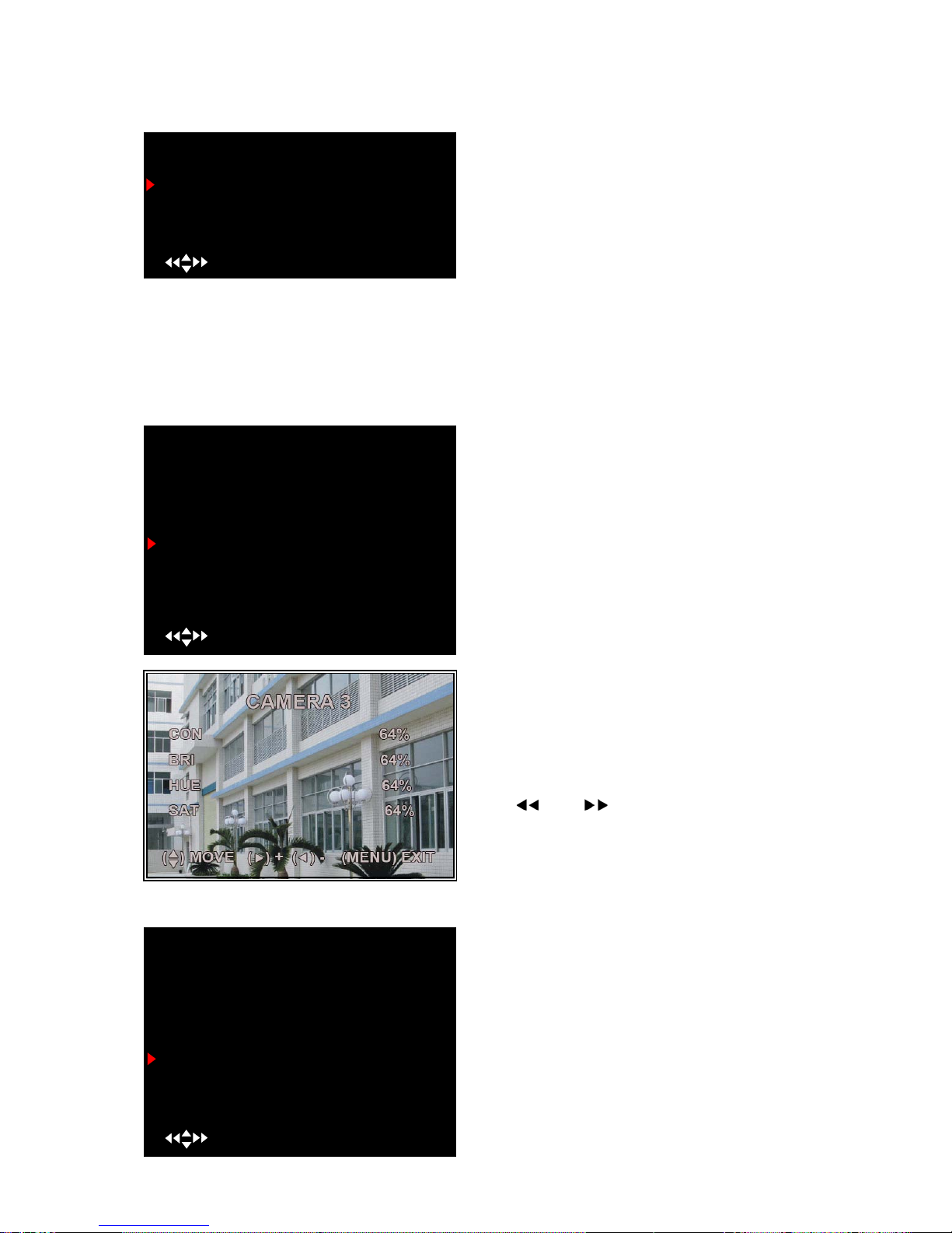
You can adjust the image parameters to meet your
needs. The controls are shown below:
CON:Contrast
BRI: Brightness
HUE:Hue (color)
SAT:Saturation (color)
Press [▲] or[▼] buttons to select the item, and
press [ ] or [ ] buttons to adjust the setting.
AUDIO PORT SETUP
AUDIO PORT 1 – VIDEO CHANNEL [ 1 ]
AUDIO PORT 1 –RECORD [OFF]
( ) MOVE (SEL)SELECT (MENU)EXIT
When you move the cursor to “AUDIO PORT RECORD” and press the “SELECT” button, the option
will be changed to ON or OFF. If the option is ON, the audio will be recorded onto the hard drive when
you press the RECORD button.
MISCELLANEOUS SETUP
CHANGE PASSWORD
SET TIME
HIDDEN CHANNEL
AUDIO PORT SETUP
IMAGE PARAMETERS
PASSWORD ENABLE
KEYPAD TONES
SEQ. DWELL TIME
VIDEO LOSS SOUND
( ) MOVE (SEL)SELECT (MENU)EXIT
[OFF]
[ CH1 ]
[ OFF]
[ ON ]
[ 30 ]
[ ON ]
When Password Enable is set to “on”, the
password will be required and must be entered
correctly; otherwise, you will not be able to enter the
system.
Entering the password will not be required if the
Password Enable is set to “off” (except of formatting
hard drive and menu reset)
MISCELLANEOUS SETUP
CHANGE PASSWORD
SET TIME
HIDDEN CHANNEL
AUDIO PORT SETUP
IMAGE PARAMETERS
PASSWORD ENABLE
KEYPAD TONES
SEQ. DWELL TIME
VIDEO LOSS SOUND
( ) MOVE (SEL)SELECT (MENU)EXIT
[OFF]
[ CH1 ]
[ OFF]
[ ON ]
[ 30 ]
[ ON ]
When you move the cursor to “AUDIO PORT
VIDEO CHANNEL” and press the “SELECT” button,
the option will be changed to “CH2”. If you push
“SELECT” button one more time the option will be
changed to “CH3” and one more time will set the
channel to “CH4”.
Page 12

User Manual
12
5.17 Miscellaneous Setup – Keypad Tones
5.18 Miscellaneous Setup- Seq. Dwell Time
5.19 Miscellaneous Setup- Video Loss Sound
5.20 Network Setup
This function allows you to enable or disable the
audio beeper sound when pressing [SEL] button to
select ON or OFF.
Press [◄◄], [►►] buttons to select Seq. Dwell
time and select “OFF” to enable or disable individual
camera sequential display.
Note: Seq. Dwell Time Option can be
1sec, 5sec, 10sec, 15sec, 30sec, or 60sec
This function allows you to enable or disable the
audio buzzer sound for video loss, when pressing
[SEL] button to select ON or OFF.
MISCELLANEOUS SETUP
CHANGE PASSWORD
SET TIME
HIDDEN CHANNEL
AUDIO PORT SETUP
IMAGE PARAMETERS
PASSWORD ENABLE
KEYPAD TONES
SEQ. DWELL TIME
VIDEO LOSS SOUND
( ) MOVE (SEL)SELECT (MENU)EXIT
[OFF]
[ CH1 ]
[ OFF]
[ ON ]
[ 30 ]
[ ON ]
MISCELLANEOUS SETUP
CHANGE PASSWORD
SET TIME
HIDDEN CHANNEL
AUDIO PORT SETUP
IMAGE PARAMETERS
PASSWORD ENABLE
KEYPAD TONES
SEQ. DWELL TIME
VIDEO LOSS SOUND
( ) MOVE (SEL)SELECT (MENU)EXIT
[OFF]
[ CH1 ]
[ OFF]
[ ON ]
[ 30 ]
[ ON ]
MISCELLANEOUS SETUP
CHANGE PASSWORD
SET TIME
HIDDEN CHANNEL
AUDIO PORT SETUP
IMAGE PARAMETERS
PASSWORD ENABLE
KEYPAD TONES
SEQ. DWELL TIME
VIDEO LOSS SOUND
( ) MOVE (SEL)SELECT (MENU)EXIT
[OFF]
[ CH1 ]
[ OFF]
[ ON ]
[ 30 ]
[ ON ]
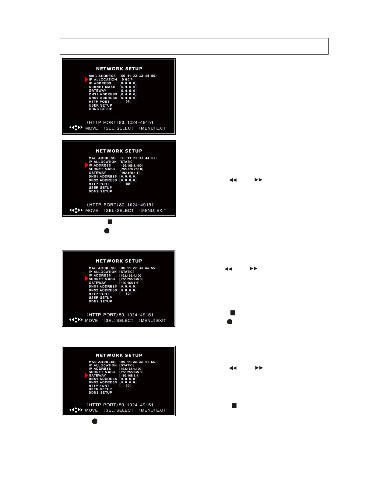
Network Setup allows you to prepare the DVR for
viewing over an internet or local network
MAC ADDRESS: In a local area network (LAN), the
MAC (Media Access Control) address is your computer’s
unique hardware identity code,
IMPORTANT: This setting should only be changed if
multiple DVRs are being setup on the same network and
the first code “00” must not to be changed.
( )
Page 13
User Manual
13
NOTE: The DVR must be restarted after changing network settings before they take affect.
Press [STOP ] to delete a number
Press [REC ] to insert a number
Press [MENU] to save and return to previous menu.
Press [REC ] to insert a number
Press [MENU] to save and return to previous menu.
SUBNET MASK: Subnet Mask is used to determine
what subnet an IP address belongs to.
Press [REW FWD ] buttons to move the cursor
to the number to be changed,
Press [▲, ▼] buttons to select the number you want
to change to.
Press [SEL] to make the change
Press [STOP ] to delete a number
Press [REC ] to insert a number
Press [MENU] to save and return to previous menu.
IP ALLOCATION: DVR supports DHCP and
Static IP modes. If your modem/router supports
DHCP mode use DHCP.
When using STATIC mode, you will be required
to setup your internet settings manually.
After setting the DVR to DHCP mode restart the unit
for your settings to take effect.
( )
IP Address: In a local network, the IP address is
a unique designated address for your DVR. Ensure
this number is within the range usable by your
network.
Press [REW FWD ] buttons to move the
cursor to the number to be changed,
Press [▲, ▼] buttons to select the number you
want to change to.
Press [SEL] to make the change
( )
( )
GATEWAY: Set this number to the gateway set
by your modem/router.
Press [REW FWD ] buttons to move the
cursor to the number to be changed, Press [▲, ▼]
buttons to select the number you want to change to.
Press [SEL] to make the change
Press [STOP ] to delete a number
( )
Page 14
User Manual
14
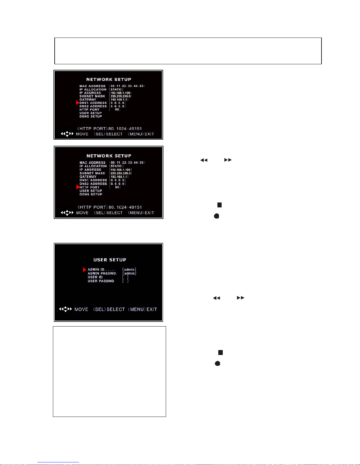
USER SETUP: When accessing the DVR from a
remote location you will be prompted for a login and
password.
User ID and USER PASSWORD are used to restrict
the access rights over a network to prevent tampering.
Press [REW FWD ] buttons to move the cursor
to the number to be changed,
Press [▲, ▼] buttons to select the number you want
to change to.
Press [SEL] to make the change
Press [STOP ] to delete a number
Press [REC ] to insert a number
Press [MENU] to save and return to previous
menu
NOTE: You only need to adjust the IP ADDRESS,SUBNET MASK and GATEWAY values,
when the [STATIC] mode is selected.
ADMIN: has full access and you can
change DVR settings, playback and
record video over a network
Default User ID = admin
Default password = 111111
USER: has limited access and can only
view live video over a network
Default User ID = not used
Default password = not used
DNS ADDRESS: This code should be
provided by your local ISP.
This is only used if DDNS is to be used with a
dynamic IP address
( )
HTTP PORT: This port number is used to
communicate with PC Client. The default value is 80.
Press [REW FWD ] buttons to move the cursor to the
number to be changed,
Press [▲, ▼] buttons to select the number you want to
change to.
Press [SEL] to make the change
Press [STOP ] to delete a number
Press [REC ] to insert a number
Press [MENU] to save and return to previous menu.
( )
( )
Page 15
User Manual
15
5.21 Language
5.22 Reset Menu
The system allows you to reset all your settings to the DVR factory default. You will
need to enter your password to reset the menu.
5.23 NTSC/PAL Output Select
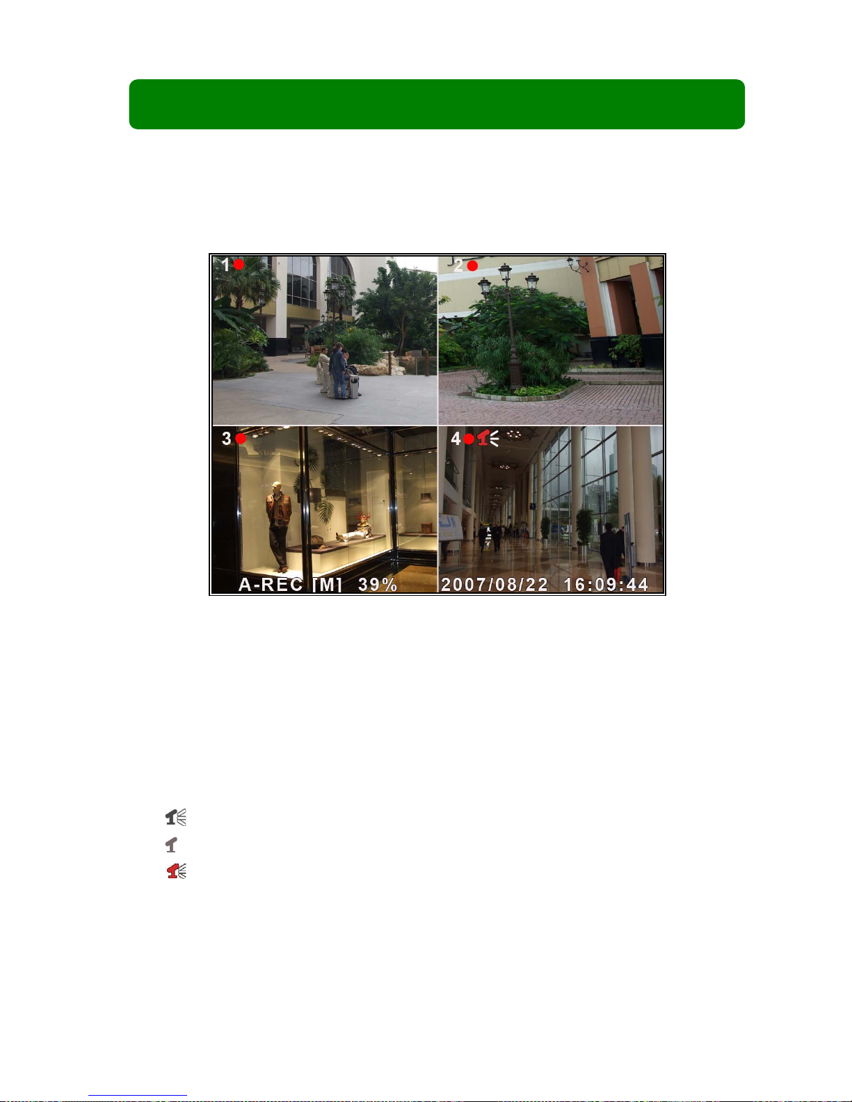
Change the jumper JS1 to select NTSC or
PAL video output format shown on the
silkscreen shown in the picture on the left. The
picture shows the setting for PAL, move the
jumper to the right side for NTSC
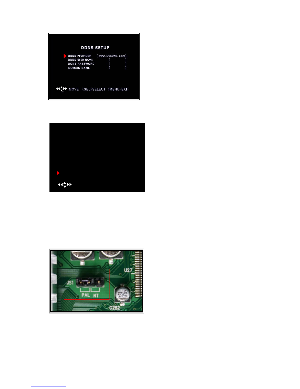
DDNS SETUP:If you require an external service
to maintain a dynamic IP address enter the user
information here.
You need to register a www.dyndns.org to get a
free account. After registration,you will have a user
name and password. You can also register your
domain name on the website.
( )
MAIN MENU
CAMERA SETUP
RECORD SETUP
RECORD FRAMERATE
VIDEO QUALITY HIGH
RECORD SCHEDULE
SENSOR SETUP
HARD DRIVE SETUP
MISCELLANEOUS SETUP
NETWORK SETUP
LANGUAGE ENGLISH
RESET MENU
( ) MOVE (SEL) SELECT (MENU)EXIT
You can change the OSD from the default
language to other language if your DVR supports
multi-language.
Page 16
User Manual
16
Chapter 6: Recording
6.1 Starting Recording
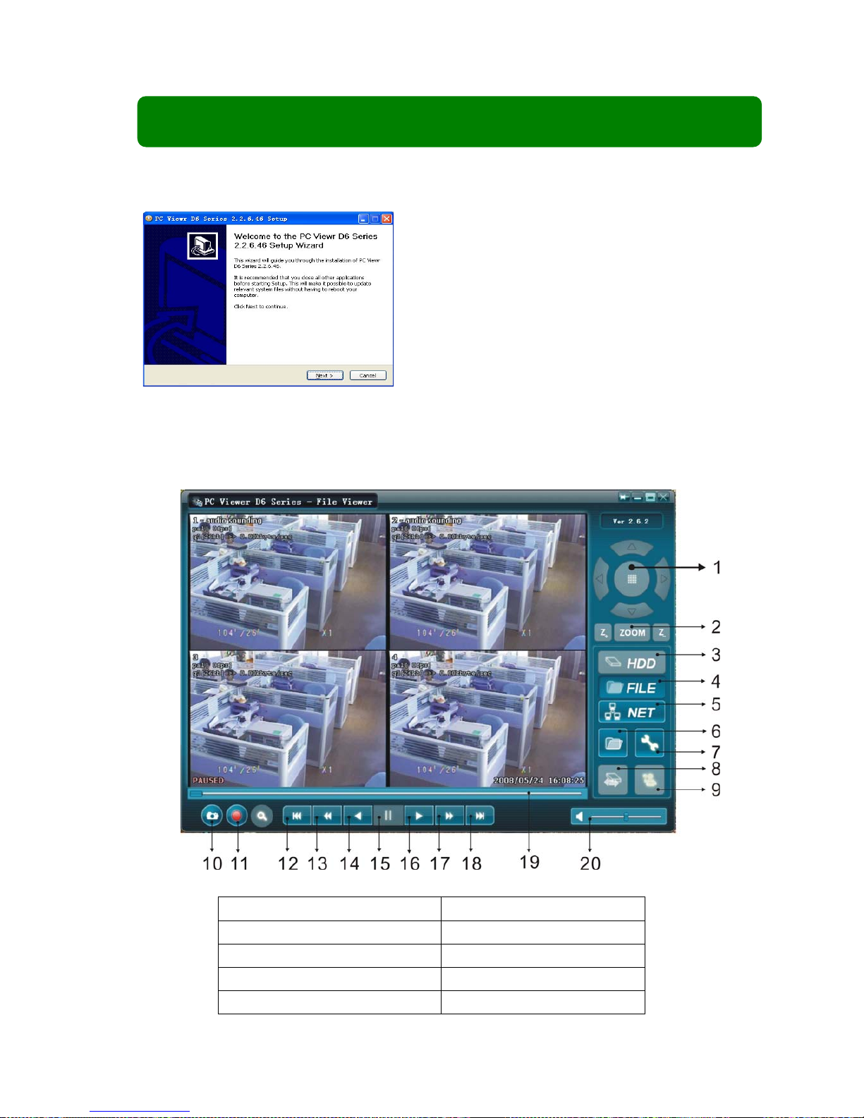
Press [●REC] button to start the record according to the record schedule you have
set. There will be a [●] red icon shown in the top left of the screen when recording.
[●]:Indicates that the channel is being recorded.
[A-REC]:Indicates the current record schedule is set to NORMAL-RECORD mode.
[S-REC]:Indicates the current record schedule is set to SENSOR-RECORD mode.
[N-REC]:Indicates the current record schedule is set to NO-RECORD mode.
[39%]:Indicates the percentage of hard disk space used.
[M]:HDD info ([M] MASTER HDD;[S] SLAVE HDD).
6.2 Audio Recording
[ ]:indicates this video channel is assigned an audio port, and the audio output is on.
[ ]: indicates the audio output is off.
[ ]:indicates the audio is being recorded and the audio output is on.
You may press the [DOWN] button on the front panel to mute the audio output. The
audio input can be still recorded while the output is muted.
6.3 Stopping Recording
Press the [■STOP] button to stop recording. If password protection function is enabled,
Page 17

User Manual
17
the system will prompt you to input your password. Only the correct password can stop the
recording process.
6.4 Estimated Recording Time
Estimated record time based on 320GB HDD (in hours)
Standard
Quality
60fps
48fps
32fps
16fps
1fps
Highest
124
156
232
464
7440
High
176
220
330
660
10,560
Normal
214
268
402
802
12,840
NTSC
Low
240
300
450
900
14,400
Standard
Quality
50fps
36fps
24fps
12fps
1fps
Highest
128
178
266
534
6400
High
180
250
376
750
9000
Normal
220
306
458
916
11,000
PAL
Low
246
342
512
1026
12,300
Unit: Hours
Chapter 7: Playback
7.1 Playback Control
Press the [►] PLAY button to go into PLAYBACK mode. The newest recorded event
Press the [MENU] button in Playback
mode. The system will list all the recorded
Page 18

User Manual
18
will be played.
SEACH VIDEO
DISK: MASTER SLAVE [NONE]
08/09/19 11:16:31 - 08/09/19 15:05:48
TYPE: EVENT TIME
PLAY: EVENT LIST
00006 T 2008/09/19 15:07:40
00006 T 2008/09/19 14:07:40
00006 T 2008/09/19 13:07:40
00006 T 2008/09/19 12:07:40
00006 T 2008/09/19 11:07:40
00006 T 2008/09/19 10:07:40
00006 T 2008/09/19 09:07:40
( )MOVE (SEL)SELECT
( ► ) PLAY (MENU) PREV MENU
Page 19
User Manual
19
Chapter 8: USB Programming
8.1 Software Installation
8.2 Program Interface
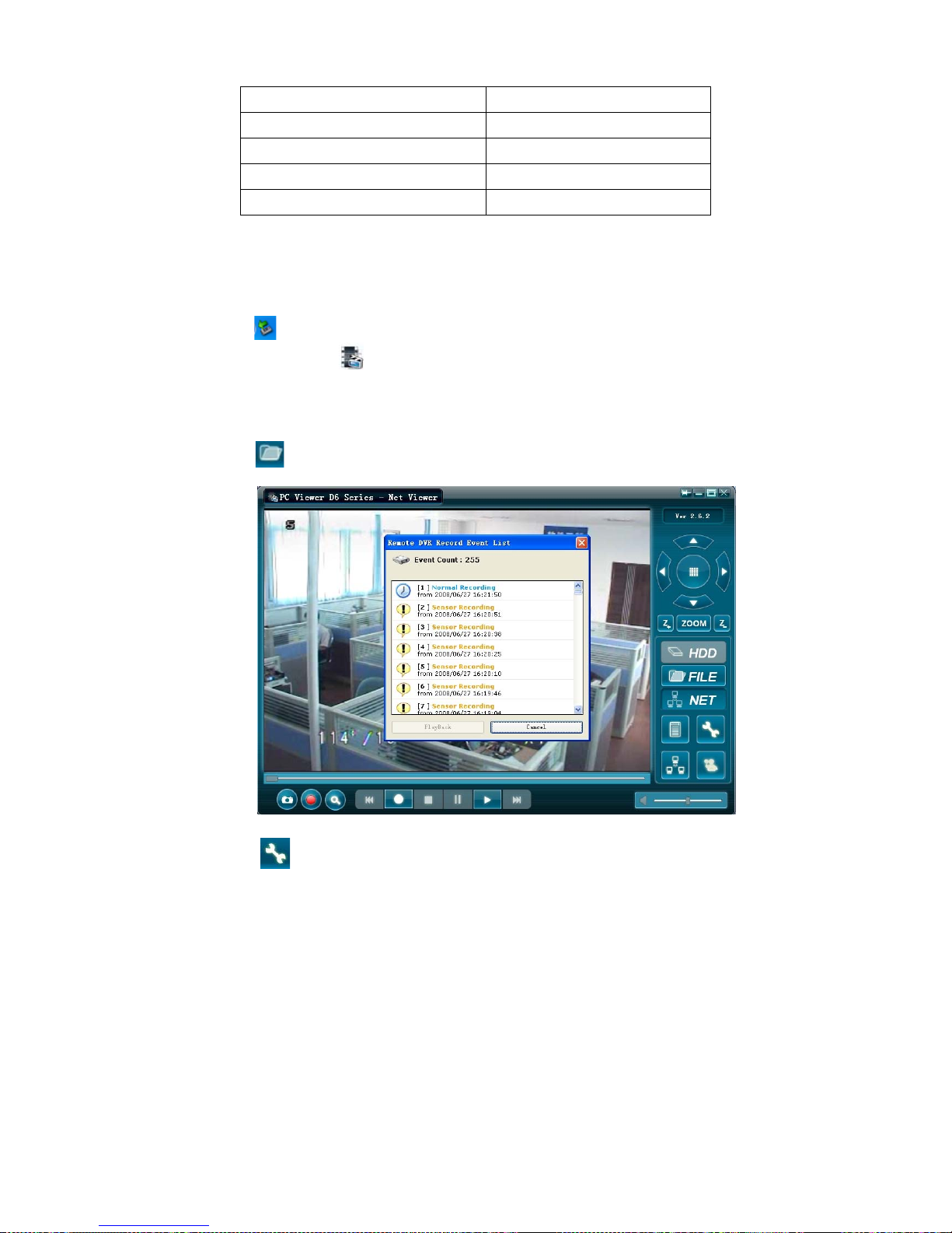
Button functions:
1、PTZ Control(not available)
11、Convert Streams to AVI file
2、Zoom in,Zoom out(not available)
12、Fast Rewind 60s
3、HDD Play Mode
13、Fast Rewind 10s
4、FILE Play Mode
14、Forward
5、NET Play Mode
15、Stop
(1) Insert driver CD to your CD-ROM driver;
(2)Open CD directory;
(3) Run “Installation” program;
(4) Follow the setup wizard to finish the installation.
Page 20
User Manual
20
6、Event List
16、Playback
7、Program Local Setting
17、Fast Forward 10s
8、Shift Storage Device
18、Fast Forward 60s
9、Remote DVR Control
19、Playback Slider
10、Capture Image
20、Audio Slider
8.3 Program Running
8.3.1 HDD Play Mode
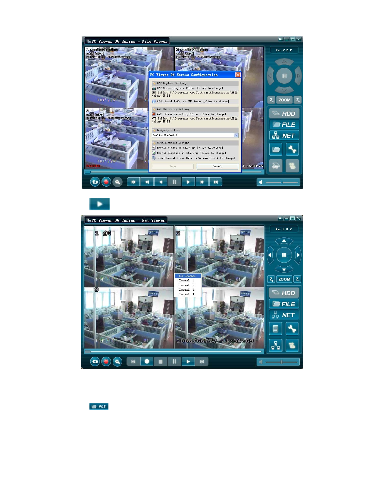
System will detect HDD automatically when you connect DVR to your PC with USB cable.
An USB icon “ ” will appear in the system tray (right bottom corner of the screen).After seeing
this icon, double-click the “ ” icon on your desktop to run the program.
Note: If you do not strictly follow above-mentioned steps, the program may fail to read recording
files.
Press the “ ” (button 6) to open the video event list.
Press the “ ” (button 7) to proceed the program local settings. E.g.: Save route settings
for capture image and AVI record files
Page 21
User Manual
21
Press the “ ” (button 16) to play video.
8.3.2 FILE Play Mode
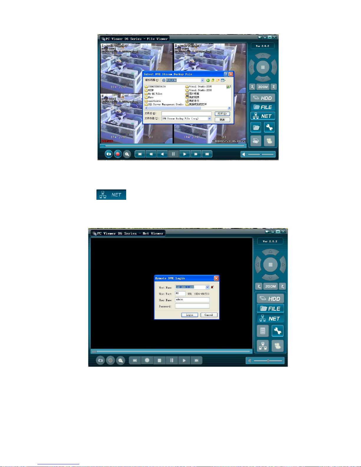
(Only when you insert a USB memory stick to your PC.)
Press the “ ” button to open a folder, select the file which you want to
Play and double click to play video.
Page 22
User Manual
22
8.3.3 NET Play Mode
This mode allows you to remote control your DVR via internet or Intranet.
Press the “ ” button to pop up a login window.
Fill in Host name, Host Port, User Name and Password of the DVR that you want remotely
access and then click Login to enter the main page.
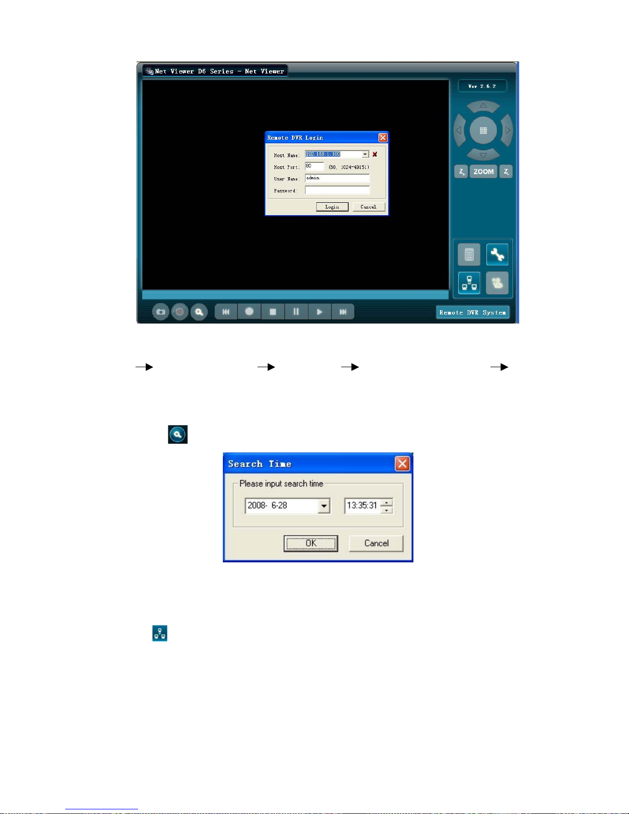
8.4 IE Remote control DVR
Enter IP address and domain name of remote DVR via Internet. (If port number is not 80,
Please add the port No. before the IP address or domain name. the system will pop up the main
page shown as below):
Page 23
User Manual
23
Note: If visiting your DVR at first time, please allow to install IE software package.( All the
selection relative to the package installation should be set to “on” after entering the below steps:
Tools” “Internet Option” “Security” “User- defined Level” “Security
Setting”).
Enter IP address, Port number, user name and password of remote DVR to login in.
Press the “ ” button, and system will pop up the below dialog box:
Enter specified time to search record file which you want, and Press “OK” button to play the
record.
Note:The function will be available only when you visit international explorer
Press the “ ” button to connect or disconnect remote DVR.
 Loading...