

One Inverter GSI-152, GSI-202, GSI-402, GSI-502, GSI-602 Operational Manual
...
Low Frequency
Pure Sine Wave Inverter
Operatinal Manual

Content
Ⅰ.Operating Instruction---------------------------2
Ⅱ.Outlook drawing of inverter---------------------3
---------------------Ⅲ.Description of front board 3
-----Ⅳ. Function setting and meaning of the button 4
--------------Ⅴ. Connection way of input & output 6
-------------------------Ⅵ.Battery wiring diagram 8
-----------------------Ⅶ.Care and maintenance 11
--Ⅷ. Convenient method of maintenance & fixing 11
-------------------------------Ⅸ. Technical Data 12
Ⅰ.Operating Instruction
1-1. Open-package in spectio n
1). After opening the pac kage, ple ase check the attached part s and
components, includ ing opera tion manual and checking wh ether the
inverter is in good cond ition?
If found any inverter broken or com ponents missing, do not turn on the
machine , feedback to the carrier o r supplier.
Note:
1). Please keep the box an d packing m aterials in case the use in future.
2). The pr oduct is very heavy (check attachmen t as reference), please
be careful to carry.
1-2. Installation no tice:
1). The pr oducts should be well-ven tilated , away from water and the
corrosive and combustible gas es.
2). Do not set it in a corner, en sure the bo ttom of the front panel, the rear
panel fan outlet and the side of the ma chine are well-ventilated.
3). The en vironment temperature s hould rem ain 0 - 40 ℃.
4). If the machine operates under l ow temperature environment, it wou ld
cause water condense, only in a abs olute dry condition can the
machine would work nor mal, othe rwise there will be a electric shock.
5). Install the inverter near the m ains input socket or nearby the switch ,
to draw out plugs then cut off mains supply once the re is an emergency.
Attention:
1). Load should be turne d off before co nnectin g to inverter and turned on
one by one after connecting compl eted.
2). The in verter should be connecte d to a socket w ith a corresponding
current protection.
3). All power sockets sho uld link wi th ground protection.
4). No matter input powe r cable ins erts to mains socket or not, the
inverter will also continue out puting possibly, turning off the inverter
can not guarantee there is no curre nt inside the machine. In order to
make sure to cut off the output of inverter, you shou ld turn off all t he
switches then turn off the main supply.
5). To load inductive appliances such a s electro motor, displayer and laser
printer, inverter capacity sho uld be twice as loading machine’s rated
power at least.
2
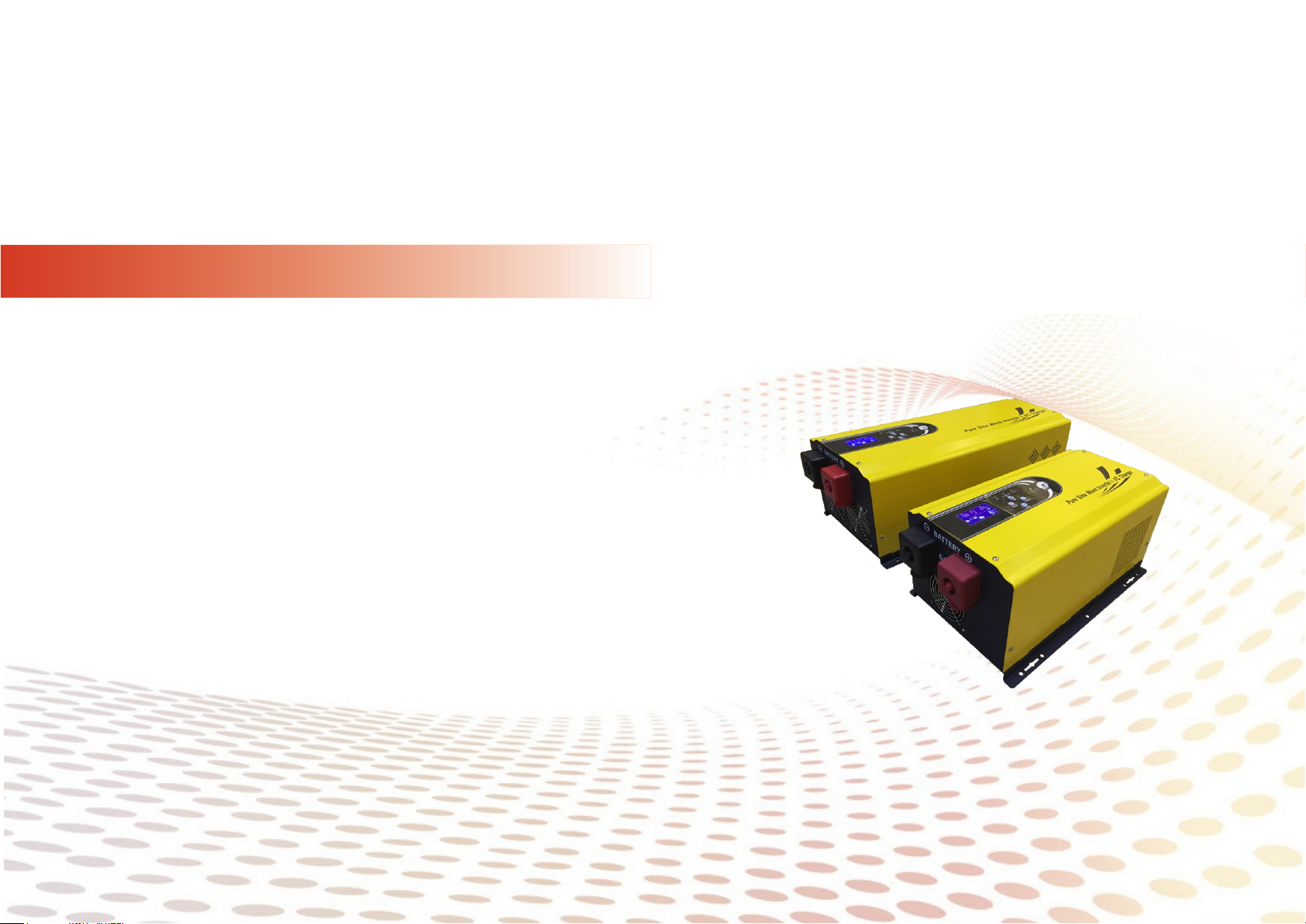
Ⅱ.Outlook drawing of inverter
Ⅳ. Function setting and meaning of the button
1. 1000W/ 200 0W/3000 W Series
2. 4000W/5000W/600 0W Series
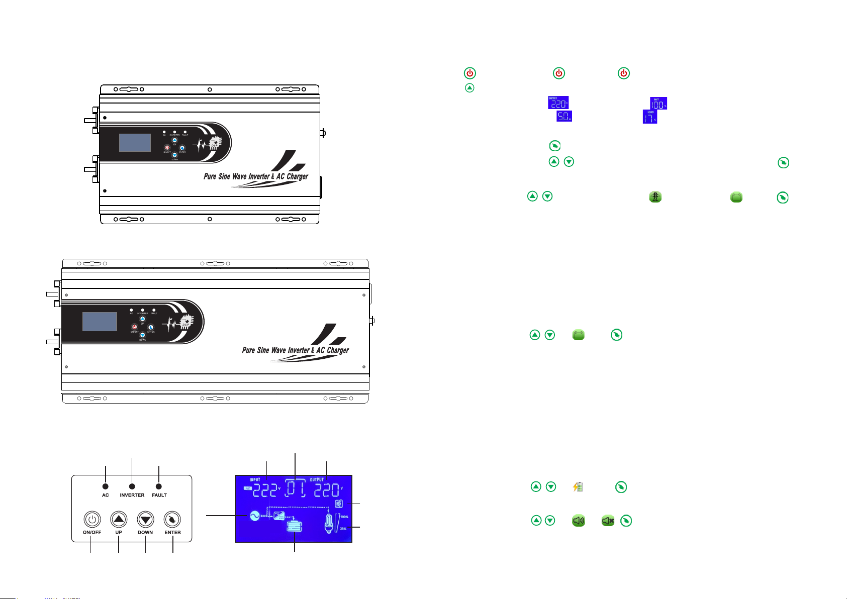
Ⅲ.Description of front board
Meanin g of i nd icate lamp&button
Battery mo de
AC mo de
Fau lt
AC voltage
Wor kin g mod e
Out put vol tag e
ON/OFF B ut ton:
3 sec. ON→
3 sec. OFF→
Press th is b ut ton to display the data below:
Output v ol ta ge , Battery capacity ,
Output f re qu ency , Load capacity .
Function Butt on :
5 sec.→ set ti ng (P0),
(P1 Working mode, P2 B at te ry t ype choose,
→
P3 Charg in g cu rrent adjust, P4)
or press t wo t im es can back to the main interface.
Model P1 :
→ (01,02 ,0 3) f irst 01:
AC
02:Aut o
03:
Batter y
01 Norma l Mo de - AC i nput priority to supply the load an d ba tt eries, battery
supply t he l oa ds without AC input.
02 Savin g Mo de - AC i nput advanced to supply the load an d th e battery,
batter y su pp ly the loads without AC input. Bu t th e lo ad must >5% of the
invert er c ap acity. otherwise the machine wi ll c on tinue to startup and
shutdo wn .
03 Batte ry M od e - Battery priority to supply the lo ad , wh en battery is low of
power or v ol ta ge, will automatically swit ch t o AC ma in s supply, whe n the battery
full of ch ar ge , automatically transfer to the b at te ry supply.
Model P2 :
→
Type
→OK
Batter y ty pe C ha rging current
(24V*2 ;4 8V *4;96V*8;108V*9;120V* 10 )
GEL U. S.A. 13. 7V
A. G . M.1 13.4V
A. G . M.2 13.7V
Sealed L ea d Aci d 13. 6V
Gel Euro pe an 1 3.8 V
Open Lea d Ac id 1 3.8 V
Calcui m (Open ) 13 . 6V
De sulph at io n cycle 14. 5V
→OK
→OK
Tur n on or t urn o ff
AC inpu t
Buzze r
Load
Model P3 :
Note:( The Max . ch ar ging current is 15A,from 0% to 100%)
Model P4 :
→
→
0-15A
or
→OK
→OK
Note: Re st ar t the inverter after each setting .
Fun ctionUp Down
Battery
43
 Loading...