

Page 1
Retain for Future Reference
Thank you for purchasing the One For
All
Wireless Universal Garage Remote. Your
One For All Wireless Universal Garage
Remote (referred to as GDK throughout
the rest of the manual) is designed to
operate most garage door openers as well
as most gate openers manufactured after
1981*.
Your GDK will operate the following
manufacturer’s products:
Before getting started, you will need your
original garage door opener transmitter.
You will use the original transmitter during
the setup of the GDK. If you do not have
your original transmitter, please refer to the
“WHAT TO DO IF YOUR ORIGINAL
TRANSMITTER HAS TWO OR THREE
BUT-TONS OR IS LOST OR BROKEN”
section after setting up your password.
.
.
.
.
.
.
.
.
.
.
.
.
.
.
.
.
.
.
.
.
.
l
Sears Craftsman (Most units)
Genie:
Model AR85 (9-Position Switch)
Model AR90 (12-Positions Switch)
Model SD9500 (12-Positions
Switch)
Stanley
Chamberlain (Most Units)
Linear
Moore-o-Matic
Multi-Code
Wayne Dalton
Lift-Master
Master Mechanics
Ambassador
Automatic DoorMan
Doorkeeper
Liftadoor
Multi El Mac
Raynor
Shima
Vemco
Crawford
Powerlift
Blue Max
EZ
Lift
Your GDK package contains the following
items:
.
1 - One For All Wireless Universal
Garage Remote
.
1 - Users Manual
.
1
- 9-volt
battery
.
2
- 1” flathead
screws for mounting the
One For All Wireless Universal Garage
Remote
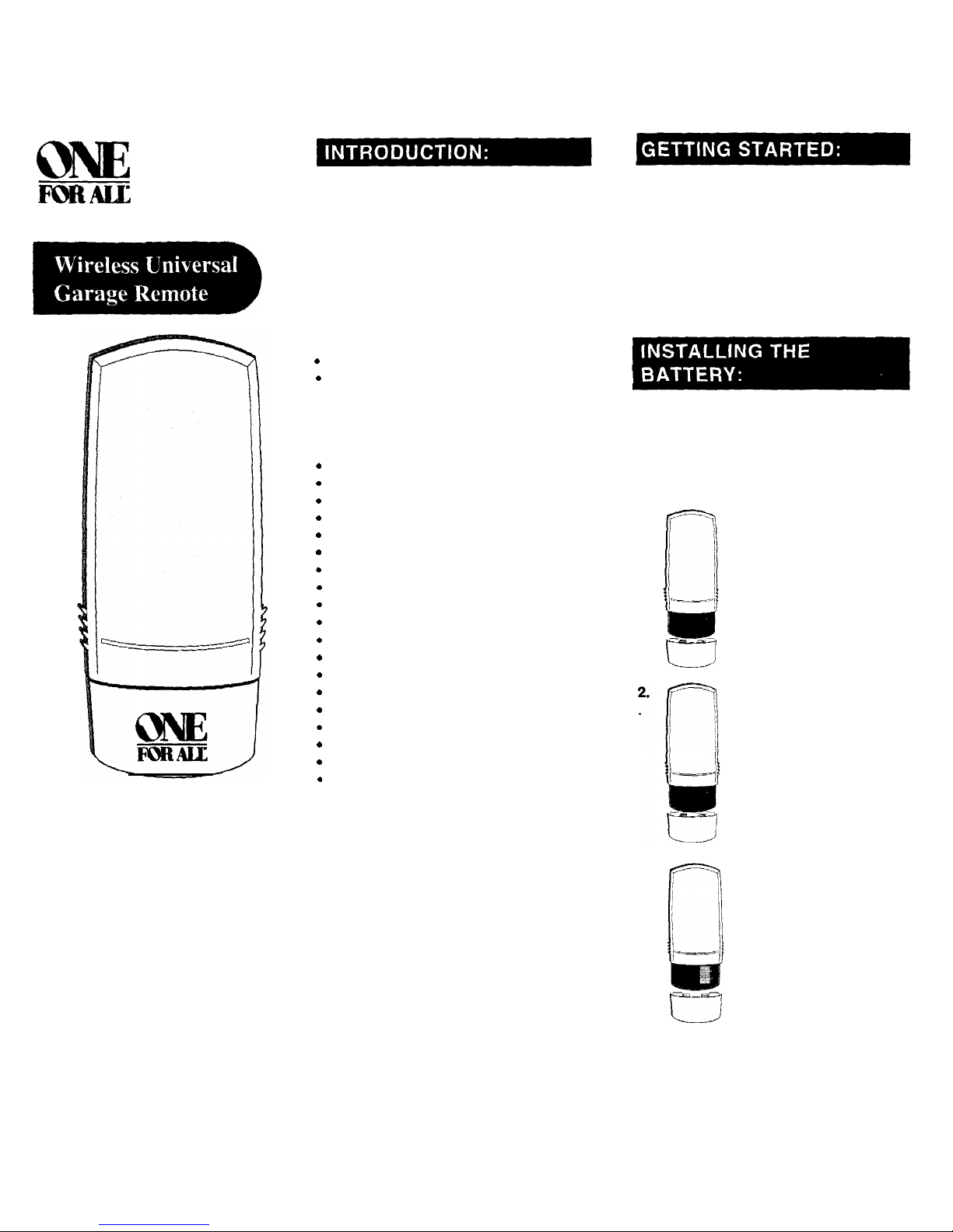
The GDK comes with one fresh 9-volt
battery. The battery is packaged inside the
battery compartment along with the two
1"
mounting screws, however, the battery is
not connected. To connect the battery:
1.
3.
Slide off the battery cover
and remove the battery and
two mounting screws.
Connect the battery.
Insert the connected battery
inside the battery
compartment and replace
the battery cover.
Page 2
1.
2.
mx8
oo*I
Slide open the cover. The GDK’s
keypad will illuminate.
Press the number 9 eight times, then
press ENTER, the GDK will beep
once and the green LED will
w
illuminate for two seconds followed
by two quick beeps. The GDK will
power OFF. This clears the GDK of
any previous passwords and
securitycodes so that you can
begin a new setup. Your GDK has
now ready to learn your new
password and garage door security
code(s).
NOTE: Use the reset code only to clear
the GDK of all passwords and garage door
security codes.
1.
Select a PIN (Personal Identification Number) and write it down.
This will be your password. Your
PIN can be up to 8 digits long.
Press the ENTERkey to illuminate
&
the GDK’s keypad.
3. w
Press tne
number 1 (Factory
’
Default Password) followed by
v
ENTER. The green LED will blink
two times followed by one beep.
The GDK is now on and ready to
learn your new password (PIN).
Pres
s STORE followed by the
PlN1, PIN2* or PIN3* key. The first
red LED, corresponding to PIN1,
will light and remain lit as the
green LED blinks.
*NOTE:
The first time you enter a
password, GDK automatically defaults that
password to PIN1, even if PIN2 or PIN3 is
pressed.
5.
PIN
Enter the PIN you wrote down in
B
STEP 1 then press ENTER. The
GDK will emit a double-ticking sound
to prompt you to confirm your new
PIN
password. Now reenter the PIN and
w
press ENTER again. If you entered
the
same PIN correctly, the green
LED will illuminate for three seconds
followed by two beeps. The GDK will
then power OFF.
NOTE: If you make a mistake in entering
your PIN, press the EXIT key and return to
STEP 2 to re-enter your new
PIN.
You will need your original garage door
opener when setting up GDK’s garage
door security code. Open your original
garage door opener so that you can view
the DIP switches.
1
.PlN
Open the GDK’s cover or, if the
w
cover is already open, press
ENTER. Key in your PIN followed
by ENTER. The GDK will beep and
the green light will blink twice if the
PIN is correctly entered. If you
enter your PIN incorrectly, the GDK
will beep and the red light will blink
once.
Press STORE followed by
DOOR1,
DOOR2 or DOOR3. The
first six
LEDs
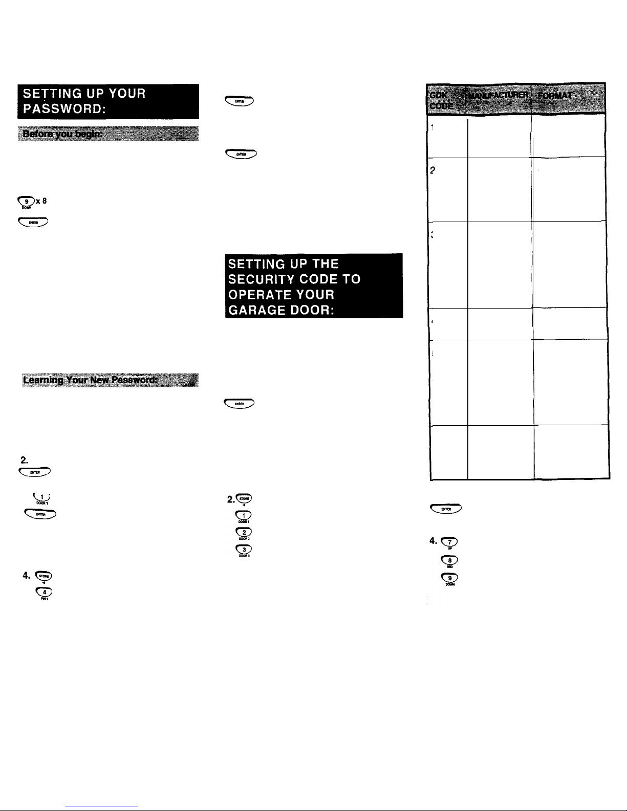
will chase. Enter the
number (1-6) from the table for
your brand of garage door
opener (See Figure 4). The
corresponding LED will light.
NOTE: If you make a mistake during the set
up
process,
press the EXIT key, re-enter your
PIN and return to
step 1 in
the
"SETTlNG
UP
THE
SECURITY CODE TO OPERATE
YOUR
GARAGE DOOR" section to
re-enter
your garage door opener’s code.
I
MULTI-CODE
AMBASSADOR
MULTI EL MAC
MOORE-O-MATIC
LINEAR
DELTA
SHIMA
POWERLIFT
3
GENIE MODEL
AT90
GENIE MODEL
SD9500
LIFTADOOR
BLUE MAX
EZ LIFT
4
GENIE MODEL
AR85
5
CHAMBERLAIN
SEARS
RAYNOR
LIFT-MASTER
WAYNE DALTON
MASTER
MECHANIC
STANLEY
6
AUTOMATIC
DOORMAN
VEMCO
10 BITS/300
MHZ
8
BITS/310
MHZ
12
BITS/390
MHZ
9
BITS/390
MHZ
9
BITS/390
MHZ
TERTIARY BITS
10
BITS/31
0 MHZ
3.
Press ENTER. All of the
LEDs
will
w
begin to chase, then the first LED
will blink.
Using the UP, MID and DOWN
keys, match the
LEDs
to the DIP
switches in your original garage
door opener. When you press UP,
the LED will remain on. When you
press MID, the LED will flash
slowly and when you press
DOWN, the LED will remain off.
NOTE: The
LEDs must m
atch exactly to
the
DIP switches on your original garage
door opener.
Page 3

5.
Press ENTER. The LEDs will now
w
be lit according to how you placed
the DIP switches. If the
LEDs
match your original garage door
opener’s DIP switches, press
ENTER
again to store your code.
The green LED will light for three
seconds then the GDK will power
OFF. Your garage door code has
now been saved in the GDK’s
memory.
NOTE:
If you have made a mistake and
one or more of the
LEDs
are not matching
your DIP switches, use
the 4-
(STORE)
or
--+
(0) keys to move the blinking LED
to the DIP that was incorrectly set. Using
the UP, MID and DOWN keys, match the
remaining
LEDs
to the DIP switches on
your original garage door opener. Once
the
LEDs
march your original garage door
opener’s DIP switches, press ENTER to
store your code.
6.
Now test your GDK. Press any key
other than EXIT, your garage door
should open.
7.
Repeat steps 1 - 5
to add a
second or third garage door to the
memory of the GDK,
IMPORTANT: With some Sears Craftsman
model transmitters, the
DIP
switch
numbering begins with the number
"2.”
When programming the GDK to Operate
one of these models, please use the
DIP
(near the head unit) rather than the DIP
switches inside your original Transmitter.
The radio receiver can be found on or near
the garage door opener motor head
mounted on
your
garage ceiling. The DIP
switches are usually located near the point
where the electrical wires enter the garage
door opener head or on the externally
mounted radio receiver.
Some Genie openers do not have DIP
switches. They have “knockout” or “punch
out” switches to set the transmitter code.
Where the hole is “punched out” on the
original transmitter, the GDK’s
LEDs
should be set in the DOWN position
(OFF). Where the hole is NOT “punched
out”, the GDK’s
LEDs should be set in the
UP position (ON). On these models, the
GDK’s
LEDs
(I-9) should never be in the
MIDDLE position (BLINKING).
If you own a Genie AR85 Garage Door
Opener, do not set LED number 9 in the
UP position (ON).
If you own a Genie AR90 Garage Door
Opener, do not set more than eight
LEDs
(out of 12) in the UP position (ON).
If the GDK will not operate your Stanley
opener, try setting the
LEDs (1-10) to the
opposite positions of your original
transmitter. For example, if you set all 10
of
the LEDs to the UP position (ON) to
match your original Stanley transmitter,
then reverse the LEDs to the DOWN
position (OFF) and test the GDK again.
Some Stanley openers do not have
DIP
switches. They have even numbered wires
located in both the original transmitter
and the head unit. Notice that
there
are no
odd numbered wires. To program the GDK
to operate one of these wired units:
Place all of the
LEDs
(1-12) in the
GDK in the down position (OFF).
Now locate the uncut wires in the
original transmitter or head unit
and, using the
+-
(STORE) or
--)
(0) keys on the GDK, move
the blinking LED to the first
number that matches the first
uncut wire in your original
transmitter. Using the UP key,
place the LED in the UP position
(ON). Continue to place all of the
uncut wires in the UP position
(ON). On these models, the GDK’s
LEDs
(1-9) should never be in the
MIDDLE position (BLINKING).
If your "Smart" or “Learning” garage
door opener has DIP switches in the
original transmitter, set the
#1
LED
on the GDK to the opposite setting of
the
#1
DIP switch in your original
transmitter. Set the remaining
LEDs
(2-9) to the exact same position as
your original transmitter.
If
your
original transmitter does not have
DIP switches, continue on to Step 2.
2.
3.
4.
5.
Reach the motor head unit and
remove the plastic cover. Find the
“Smart” or “Learn” button on the head
unit. The button should have an LED
(Light Emitting Diode) next to it.
After setting the manufacturer’s code,
set the
LEDs
on the GDK to any
position you like, and store the
code to DOOR1, DOOR2 or DOOR3
as described in the “SETTING UP
THE SECURITY CODE TO
OPERATE YOUR GARAGE DOOR”
section.
Press and hold the button on your
GDK where you stored your code.
While holding down that button,
press
the “Smart” or “Learn“ button,
see Figure 5 (below), on the head
unit. After the light on the head unit
flashes, release both buttons.
oo’i
END PANEL
i/
I
II J
Test the GDK by pressing any
button other than EXIT. Your garage
door should respond.
Please Note: You
have now added
the
access code of your GDK to the radio
receiver. However, your original
transmitter may nor be able to
communicate wirh
the
opener. If this is
the case, erase
the
memory of your radio
receiver by pressing and holding the
“Smart” or “Learn” button on the head unit
for approximately 10 seconds. Now,
relearn your original transmitter by
pressing and holding the button on your
original transmitter. While holding down
that button, press the “Smart” or “Learn”
button on
the
head unit. After
the
light on
the head unit flashes, release both
buttons. Then, relearn the GDK.
If
this fails
to
make both transmitters compatible with
your garage door opener, then erase the
memory of your radio receiver and relearn
the
original transmitter and march the
GDK’s LEDs to the D/P switches in the
original transmitter.
Page 4

2.
Slide the GDK onto the screw, see
figure 6.
Figure 6
If your original transmitter has two or three
buttons and uses DIP switches, set the
#1
LED in the GDK to the opposite position
on the first DIP switch of your original
transmitter. Set the remaining GDK LEDs
to the exact same position of your original
transmitter’s DIP switches. If your original
transmitter has two or three buttons but
does not have DIP switches inside the
original
transmitter or if the original
transmitter is lost or broken, please use
the DIP switches located on the radio
receiver (near the head unit) or at the push
button located on the garage wall. The
radio receiver can be found on or near the
garage door opener motor head mounted
on
your garage
ceiling.
The
DIP switches
are usually located near the point where
the electrical enter the garage door opener
head or on the externally mounted radio
receiver. YOU DO NOT NEED TO
DISASSEMBLE THE GARAGE DOOR
HEAD OR RADIO RECEIVER TO
LOCATE THE DIP SWITCHES,
HOWEVER, YOU MAY HAVE TO
REMOVE THE PROTECTIVE COVER.
The GDK should be mounted to an outside
wall, close to your Garage Door. Mount
the GDK on a flat vertical surface with
enough room above the GDK to slide the
cover up. The location should be easily
reached by anyone who will use it, at least
five feet above the floor and clear of any
moving Garage Door parts. It is
recommended that you choose a location
that is not in direct sunlight. If you mount
the GDK in a location that is exposed to
direct sunlight, the LEDs will be difficult to
see. It is also recommended that you do
not mount the GDK onto a metal surface,
as this may reduce the range of the signal.
To mount the GDK:
1.
Using one of the supplied
1”
screws, drive the screw into the
wall in your chosen location,
leaving
1/4”
of the screw
protruding from the wall.
3.
4.
3.
4.
Remove the battery cover and
disconnect the battery. This will not
erase the passwords or security
codes already stored in the
GDK’s
memory.
Drive the second 1” screw through
the hole at the rear of the battery
compartment.
Remove the battery cover and
disconnect the battery. This will not
erase the passwords or security
codes already stored in the
GDK’s
memory.
Drive the second 1" screw through
the hole at the rear of the battery
compartment.
Figure 7
Insert Screw
NOTE:
Make sure that the GDK is aligned
in an upright position before driving in the
second screw.
5.
Re-attach the battery and slide
battery cover back into place.
After you have stored your garage door
opener(s) security codes in the memory
the GDK and you have mounted the unit
you are ready to use your GDK. To open
your garage door:
1. PIN
Open the
GDK’s
cover or, if
the
w
cover is already open, press
ENTER. Key in your PIN, then
press ENTER. The GDK will beep.
NOTE: If you enter an incorrect PIN the
times, the GDK will lock you out for on.
minut e. After one minute, re-enter the
correct PIN to proceed with opening you
garage door.
Press DOOR1, DOOR2 or
DOOR3, depending on which door
you would like to open. The GDK
will send a signal to your garage
door opener for as long as the
DOOR1 , DOOR2 or DOOR3 key
is pressed. Once you release one
of the keys, the signal will stop.
Your garage door will open. Thirty
seconds after the last key press,
the GDK will power off.
NOTE:
After selecting the door to be
operated by pressing DOOR1 , DOOR2 or
DOOR3, pressing any key other
than EXIT
will open or close that specific garage
door.
If, after opening DOOR1, you
would then like to open DOOR2 or
DOOR3, press the EXIT key once
and then press DOOR2 or DOOR3
to open another door.
A
A
A
Do NOT allow children to play with
the transmitter or door opener, If
children must use the GDK, please
supply proper training first.
Keep people clear of the garage
door as it is opening and closing.
The garage door could cause
serious injury or death.
Use the GDK only when you are
sure that all possible obstructions
have been removed.
Page 5

This equipment has been tested and found
to comply with the limits for a class B
digital device, pursuant to part 15 of the
FCC Rules. These limits are designed to
provide reasonable protection against
harmful interference in a residential
installation. This equipment generates,
uses and radiates radio frequency energy
and if not installed and used in accordance
with the instructions, may cause harmful
-interference to radio communications.
However, there is no guarantee that
interference will not occur in a particular
installation. If this equipment does cause
harmful interference to radio or television
reception, which can be determined by
turning the equipment off and on, the user
is encouraged to try to correct the
interference by one or more of the
following measures:
The user is cautioned that changes and
modifications made to the equipment
without the approval of the manufacturer
could void the user’s authority to operate
this equipment.
FCC Authorization Label
This device complies with part 15 of the
FCC Rules.
Operation is subject to the following two
conditions:
1)
This device may not cause harmful
interference and
2)
This device must accept any
interference received,including
interference that may cause undesired
operation.
Reorient or relocate the receiving
antenna
Increase the separation between the
equipment and receiver
Connect the equipment into an outlet
that is different from that to which the
receivers connected
Consult the dealer or an experienced
radio/television technician for help
UERSAL
c
ELECTRONICS
You in Control of Today’s Technology
 Loading...