

One Electron SEA-1 Owners manual
SEA-1 – Triple 2A3 Amplifier
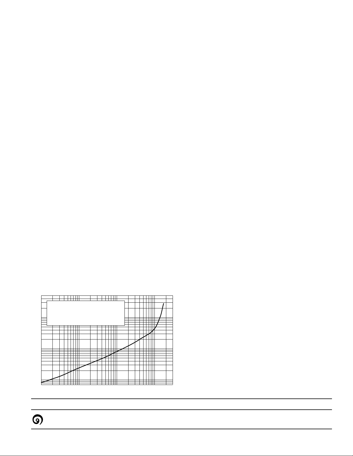
.01W
.1% 1% 10 %
.1W 1W 10 W
Harmonic Distortion vs Output Power
SEA-1 Amplifier
1000 Hz, 8 Ohm load, RCA 2A3's
General Description
he SEA-1 amplifier is a straightforward single-ended audio
T
power amplifier that delivers about 11 watts, using only
dium and low-mu triod
me
other than local cathod
or semiconducto
amplifie
r is characteristic of triodes: smooth and detaile d.
rs are used in the design. The sound of the
es. No negative fee
e degenerat
ion. No voltage regulation
Despite the lack of feedback, the bass is surprisingly solid.
his amplifier has been teste
T
no incompatib
need for relat
ilities have been f
ively efficient speakers (approx. 90 db/watt or
d on a variety of speak
ound, except, of course, the
better).
The SEA-1 was designe
T-1 transformer
UB
the SEA-1 was designed t
power suppl
could not be inc
y. There is no reason w
luded on the same chassis as the amplifier
long as hum-inducing comp
ransf ormers, ar
t
circuits.The s
upply needs to prov
and 6.3 volts AC at 1.8 Amps. Filt
hokes are incorpo
filter c
Dressen-Barnes mo
d to e valuate the prototypes of the
s. In order t
o provide flexibilit
o be used with a separate e
hy the power suppl
onents, such as po
e kept away fro
m the amplifie r driver
ide 395 volts DC at 160 ma,
ering is not critical, since
rated into the amplifier. A s
del 30180 “Unregulat
was used for each channel in the SEA-1 protot
citor or choke-input power supply
capa
RCA Rec
eiving Tube Manual
or Radiot
Handbook,can be used.
te that this amplifier description is intende d to aid
No
nced tube amplifier designers and builders.
experie
little experience b
uilding vacuum tube audio amplifiers should
not attempt to build this amplifier bas ed on just this
dback is used,
ed Power Suppl
ypes. A simple
, as described in the
ron Designer’s
ers, and
y in testing,
xternal
, as
wer
urplus
y”
People with
cription.
des
The voltages used in this amplifier are lethal!
Precautions for working on high voltage equipment must be
followed.
Measurements:
Frequency Response:10 Hz to 44.5 KHz (-3db at 1W)
Output powe
nsitivity:
Se
Damping F
All measurements were made into a low-inductance 8 ohm resistor
connected t
r and Harmonic Distortion: see graph below
22 db (to 8 ohm tap)
actor: 3.5
o the 8 ohm output tap.
Circuit Operation
Choke-capacito
driver stages. Se
y
uces feedback fr
red
r filters are used for b
parating the power s
om the output to the driver
insure the highest possible B+ v
cating the filter chokes on the amplifie
Lo
the power s
noise. Every e
capacito
capacitors whe
The input stage is a conv
upply helps isolate the amplifier from e
lectrolyt
r. R20 is a bleede
n powered-d
ic capacitor is parallele
r resistor to help drain the filte
own.
ent ional resistance-coupled
amplifier using the octal 6J5 or 6C5. The metal ver
preferred here,d
nvelope. The cathode is only partly b
the e
R3 and R4 was chosen to give an overall amplifier
of
sensitivity o
The se
cond driver stage, using par alleled se ct
ue to the electrical and magnetic shielding of
f 22 db.
6BL7GTA, has the difficult task of dr iv
capacitive inputs of the three 2A3’
to-peak.Despite the re
latively low plate resistor of 12.1K,
stage is still the limiting factor in the over
nse. An unbypassed cathode resistor reduc
respo
in this stage, but this raises the outpu
lowering the high freq
uency response. To compensate for
this, the small capacitor C8 was adde
and reduce phase shift at high frequencies. C1 ser
same purpose f
“Cathode Compe
amplifiers.C1 and C8 were c
flattest overall fr
The output stage is cathod
drop in the cathode resistor
or the first stage. This type of circuit is calle
nsation” and was develo
hosen experimentally to give the
equency and phase response.
e biased, with about 20 volts extra
s to allow a bias a djustment,
using R13.Medium and low frequencies are bypasse
oth the output and
upply filtering this way
oltage to driver tub
r chassis instead of
d with a film
ypassed. The ratio
ing the hig hly
s at up to 100 volts peak-
all high frequency
t drive impedance,
d to even the response
ped for video
, and helps
e V2.
xternal
r
sion is
ions of a
this
es distortion
ves the
d
d around
Application Note SA-1,rev 1.02 Pag
65 Washington Street, Suite 137
one electron
™
Santa Clara, California 95050 USA
© 1994 John A
y copied,as long as this copyrig
freel
twood,One Electron. This d
ocument may be
ht notice is included.
e 1
 Loading...