

Page 1
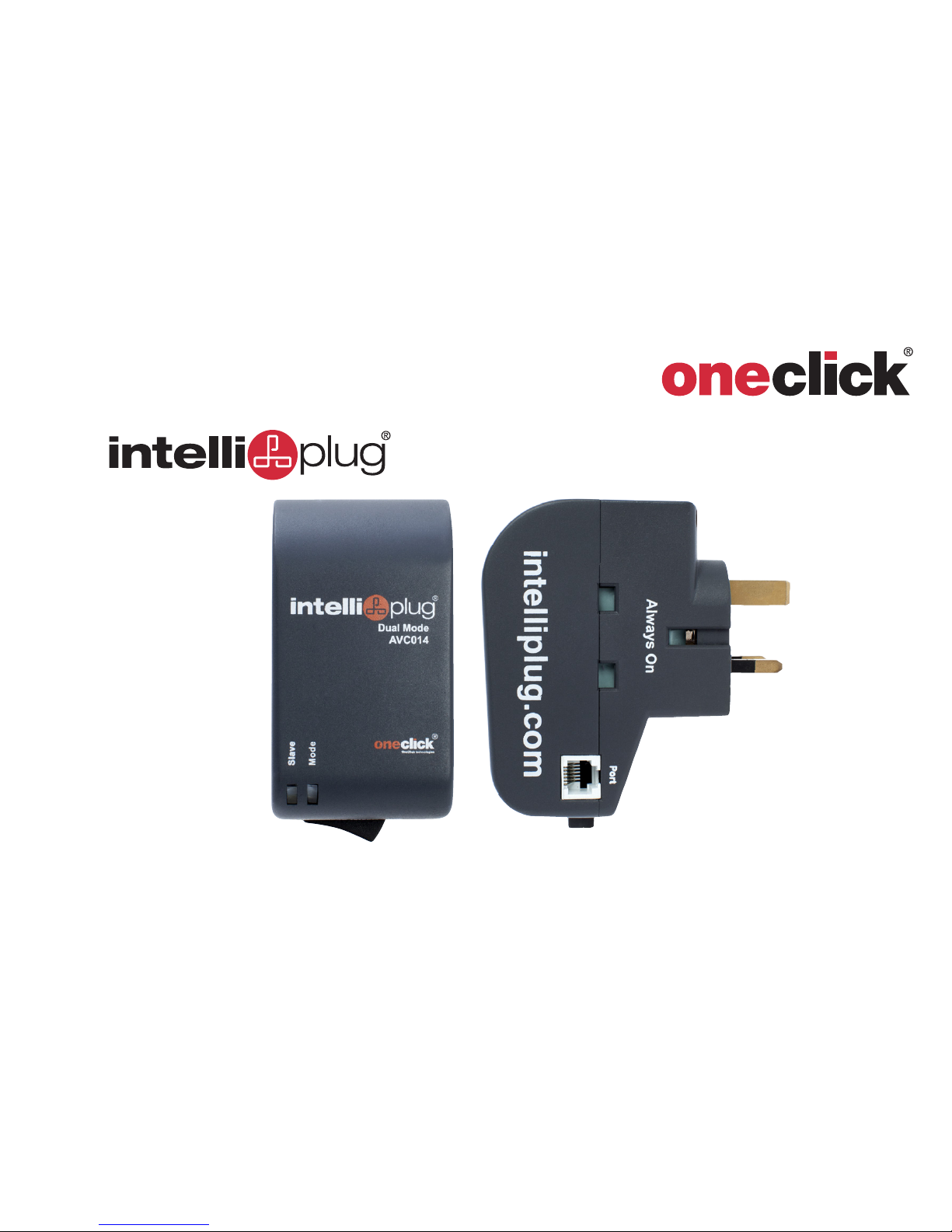
USER MANUAL
AVC014
Dual Mode
OneClick technologies
Page 2

Section
1
2
3
4
5
i
Dual Mode IntelliPlug AVC014
TABLE OF CONTENTS
Tab le of C ontents
Introduction 1
Package Contents 1
Overview 2
Features 2
Equipment Requirements 3
Unit Display Diagrams 4
Specifications 7
TV - Audio / Visual Mode
8
Installation / Configuration 8
Operating the Intelliplug 15
Optional Remote Control Paring 18
Optional Timer Facility 20
Frequently Asked Questions 22
Troubleshooting 23
Desktop Laptop Computer Mode 24
Installation / Configuration 24
Frequently Asked Questions 27
Information 28
Page 3

1
Dual Mode IntelliPlug AVC014
INTRODUCTION
SECTION
Tab le of C ontents
1
2
3 4 5
Thank you for purchasing this One Click IntelliPlug.
This device will manage power to your
television, AV equipment or computer,
to save on energy bills.
This User Manual provides all the details you’ll need
to install and operate your new One Click IntelliPlug,
in addition to troubleshooting advice,
in the unlikely event of a problem.
Package Contents
• One Click IntelliPlug
• Remote Sensor
• RJ12 Cable
• User Manual
Page 4
2
Dual Mode IntelliPlug AVC014
OVERVIEW
SECTION
Tab le of C ontents
1 3 4 5
2
Features
• Isolates power
• Saves money
• Adds convenience
LED Indicators
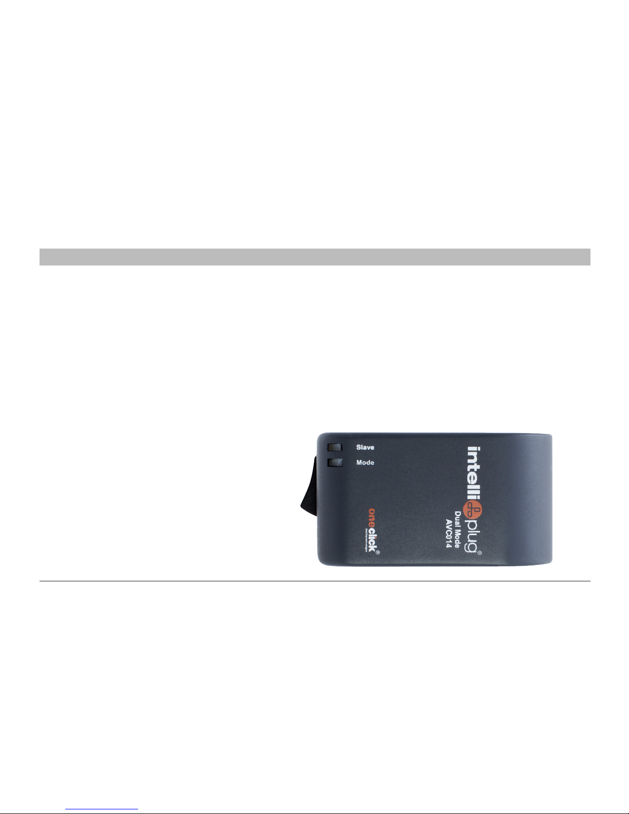
The One Click IntelliPlug has 2 LED indicator lights
that will illuminate when the Mode
and the Slave is in use.
Refer to page 17 regarding the lights.
Page 5
3
Dual Mode IntelliPlug AVC014
OVERVIEW
SECTION
Tab le of C ontents
1
2
3 4 5
Equipment Requirements
Before you begin:
• Carefully read all the instructions before
operating the One Click IntelliPlug
• Do not engulf the One Click IntelliPlug
in any sort of liquids or water
• Use the One Click IntelliPlug indoors only
• Ensure the plug is connected properly into
the wall socket and that connected equipment
is secure before switching on at the wall socket
• Do not use the One Click IntelliPlug with fish tanks
or other water-related appliances
• To be used
only with 3-pin plugs rated 220-240VAC
• Do not use the One Click IntelliPlug on boats
or moving vehicles
Do not insert a 2 or 3 point adapter directly into the
IntelliPlug; use a power distribution panel
as illustrated on page 12
• Do not use the One Click IntelliPlug outdoors
• Do not use the One Click IntelliPlug with electric heaters
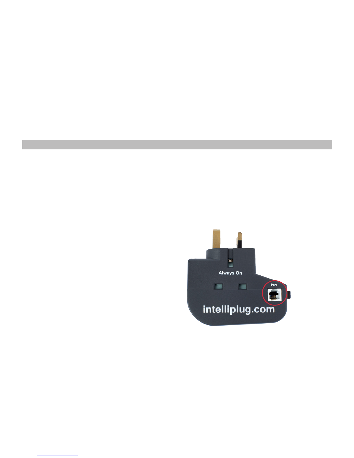
• Do not plug telecommunication equipment or any other
item that is not an authorised One Click accessory into
the PORT on the IntelliPlug as illustrated below
•
Page 6
4
Dual Mode IntelliPlug AVC014
OVERVIEW
SECTION
Tab le of C ontents
1
2
3 4 5
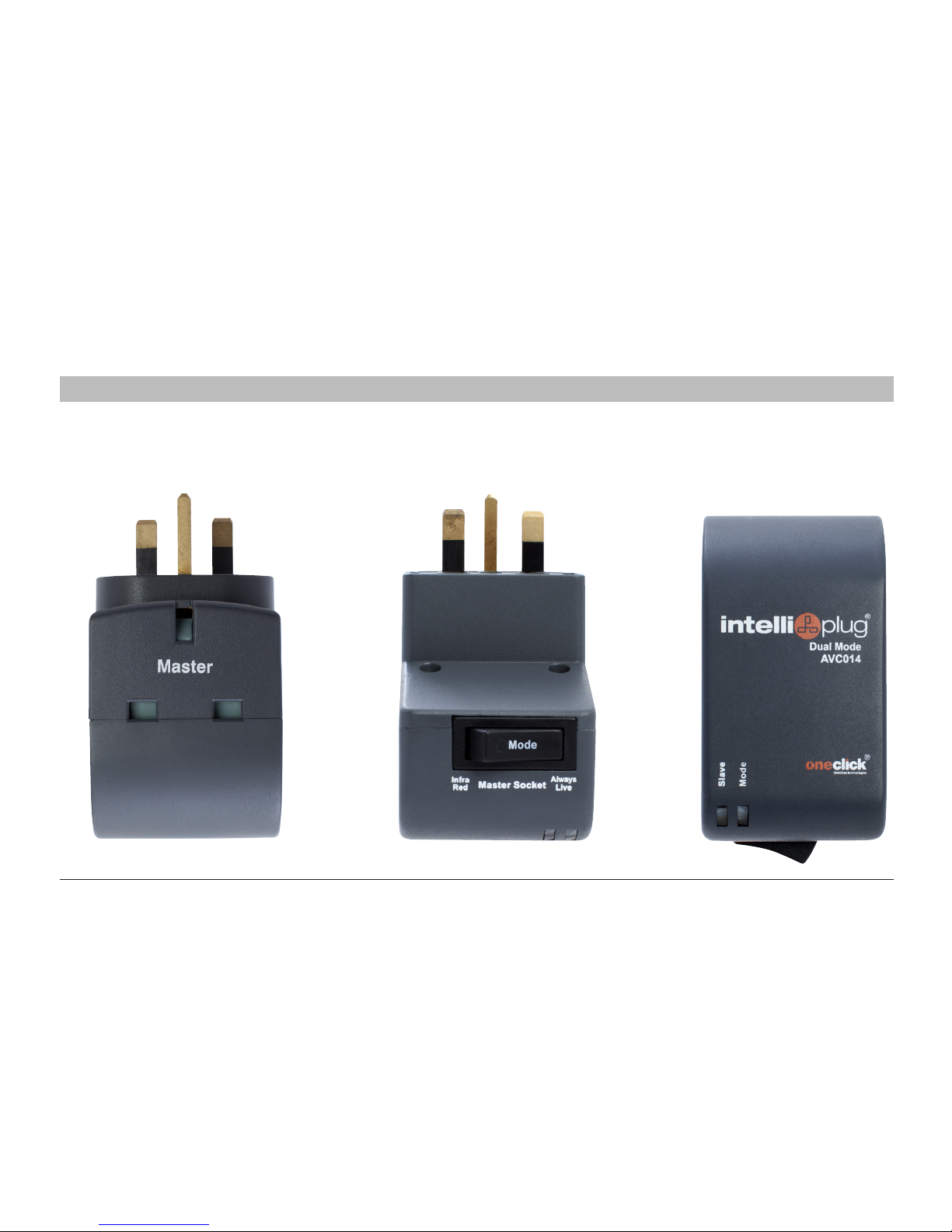
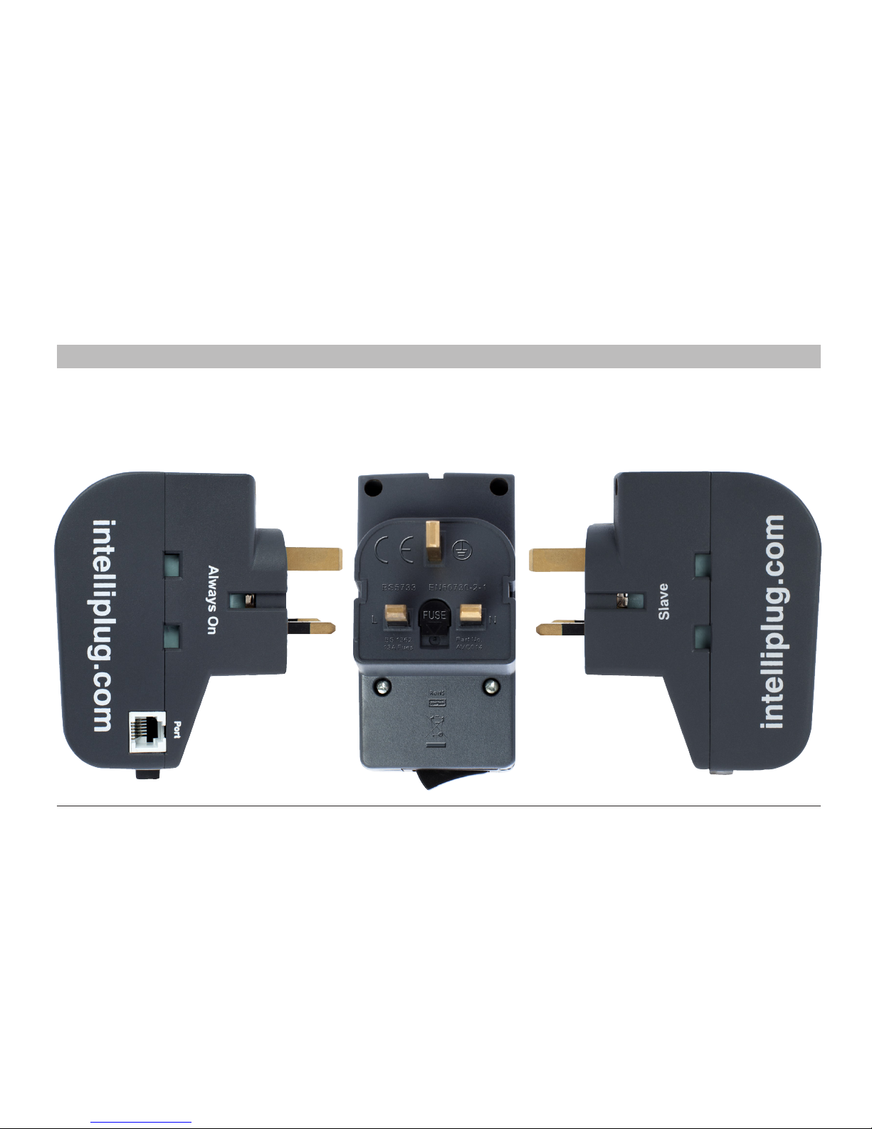
Unit Display Diagrams
Top View
Front View Bottom View
Page 7
5
Dual Mode IntelliPlug AVC014
OVERVIEW
SECTION
Tab le of C ontents
1
2
3 4 5
Side View
Page 8
6
Dual Mode IntelliPlug AVC014
OVERVIEW
SECTION
Tab le of C ontents
1
2
3 4 5
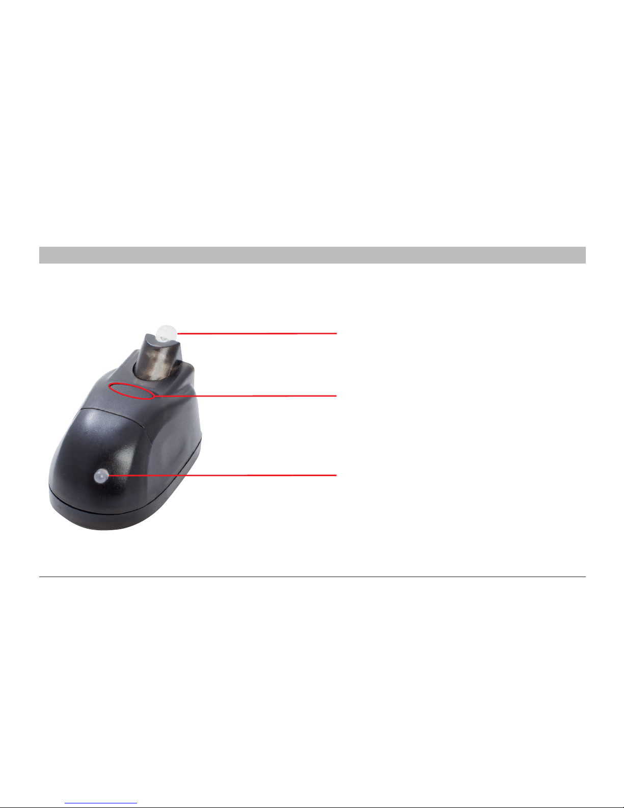
Remote Sensor
.
Infra-red Transmitter
(for use with the timer facility see page 20)
Programming / Activation Button
LED Sensor
Page 9

7
Dual Mode IntelliPlug AVC014
OVERVIEW
SECTION
Tab le of C ontents
1
2
3 4 5
Part No.: AVC014
Enclosure: High-impact plastic
AC Input: 240VAC
Rated impulse voltage: 2500V
Pollution degree: 2
Disconnection means: Type 1B
Automatic action: 6000 cycles
Specifications
:
Total Loading: 13 Amp 3000W 50Hz (fused 13A)
Device standby power usage: 0.35W
No. of sockets: 3
Warranty: 1 year
Made in China
Page 10
8
Dual Mode IntelliPlug AVC014
SECTION
Tab le of C ontents
1
2
3 4 5
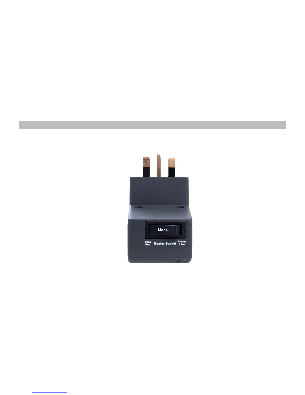
Step 1 Make sure that the One Click IntelliPlug Master Socket Mode switch is set to Infra Red
INSTALLATION - CONFIGURATION for TV - Audio Visual Mode
Page 11
9
Dual Mode IntelliPlug AVC014
INSTALLATION CONFIGURATION for TV - Audio Visual Mode
SECTION
Tab le of C ontents
1
2
3 4 5
Where to place the device:
The One Click IntelliPlug is designed for your equipment.
Consider the following when deciding where to place the
One Click IntelliPlug:
• the proximity of the One Click IntelliPlug to the equipment
• the lengths of the cables attached to your adapter
Connection and Installation
Step 1 Disconnect your existing power distribution panel
from the wall socket
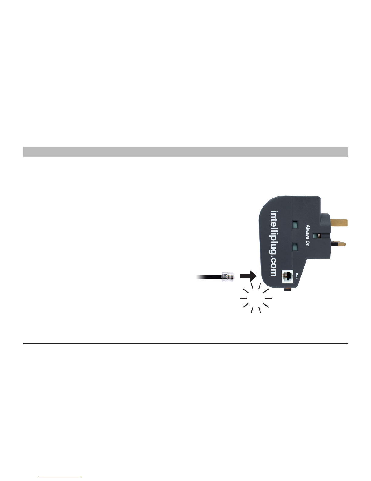
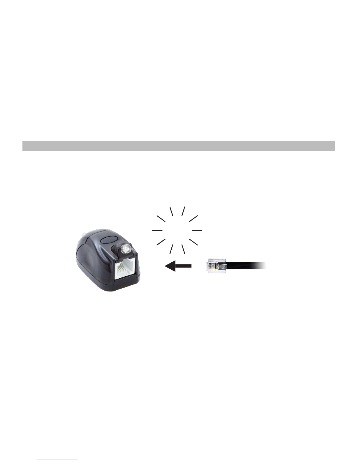
Step 2 Connect one end of the supplied RJ12 cable to
the One Click IntelliPlug as illustrated.
Warning:
Before attempti
ng to connect anything to the One Click IntelliPlug,
please ensure that all connected equipment and devices are powered off
.
CLICK
Page 12
10
Dual Mode IntelliPlug AVC014
SECTION
Tab le of C ontents
1
2
3 4 5
INSTALLATION CONFIGURATION for TV - Audio Visual Mode
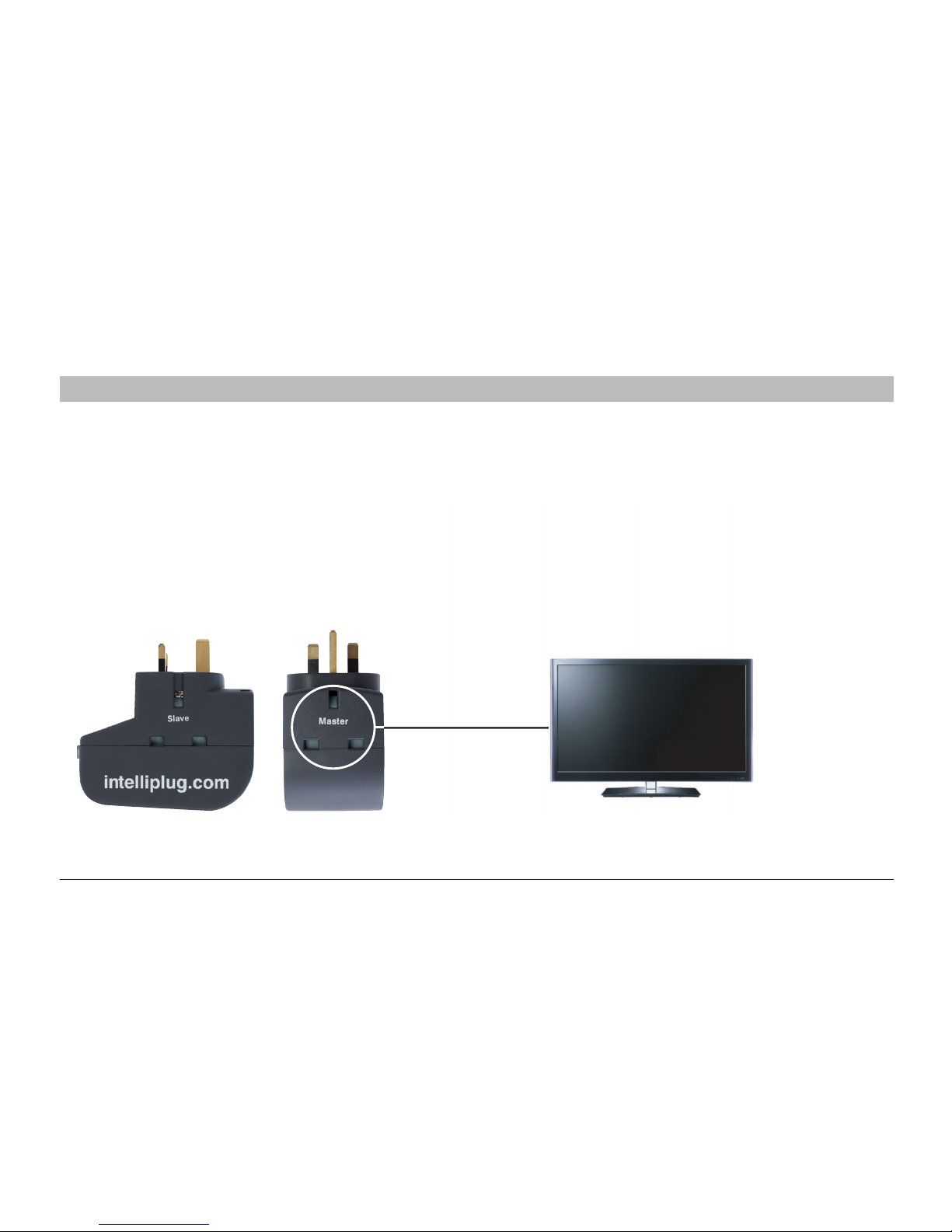
Step 3 Connect the other end of the supplied RJ12 cable to the Remote Sensor as illustrated.
CLICK
Page 13
11
Dual Mode IntelliPlug AVC014
SECTION
Tab le of C ontents
1
2
3 4 5
INSTALLATION CONFIGURATION for TV - Audio Visual Mode
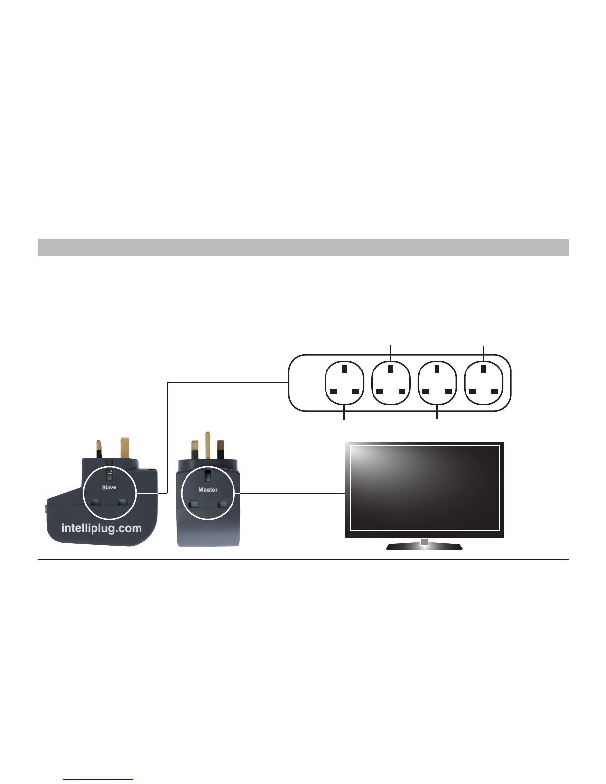
Step 4 Connect your television to the master socket on the One Click IntelliPlug.
Page 14
12
Dual Mode IntelliPlug AVC014
SECTION
Tab le of C ontents
1
2
3 4 5
INSTALLATION CONFIGURATION for TV - Audio Visual Mode
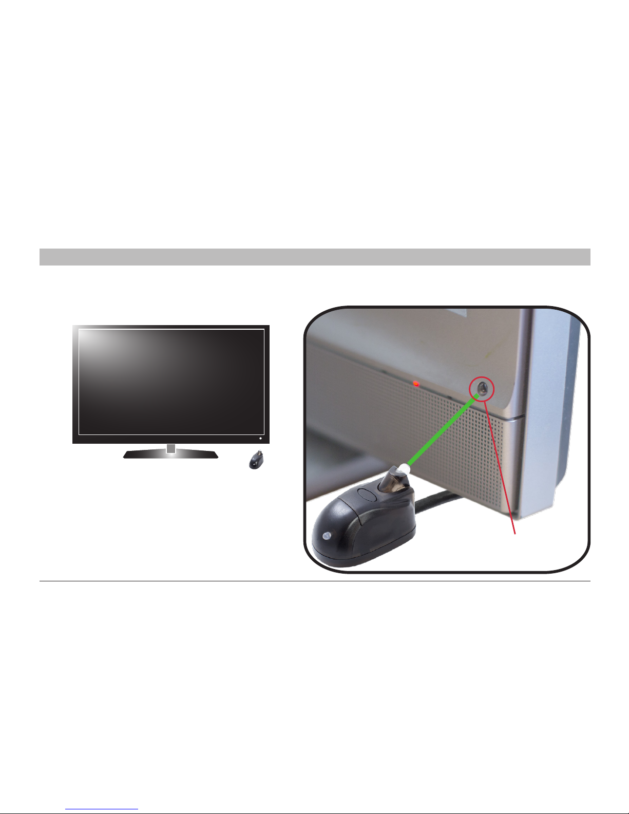
Step 5 Connect your devices using a power distribution panel (not supplied) to the slave socket on the IntelliPlug.
For items that may require continuous power, such as, a Hard Disc recorder, Video recorder or DVD recorder
see page 14.
Sub Woofer Lamp
Games ConsoleAV Amplifier
Page 15
13
Dual Mode IntelliPlug AVC014
SECTION
Tab le of C ontents
1
2
3 4 5
INSTALLATION CONFIGURATION for TV - Audio Visual Mode
Step 6 Plug the One Click IntelliPlug into the mains socket, turn the power on and position the Remote Sensor
in line of sight by your television.
NB When using the optional timer facility (page 20),
ensure the Remote Sensor is placed in front of
the infra-red reciever of the television.
Television Infra-red Reciever
Page 16
14
Dual Mode IntelliPlug AVC014
SECTION
Tab le of C ontents
1
2
3 4 5
INSTALLATION CONFIGURATION for TV - Audio Visual Mode
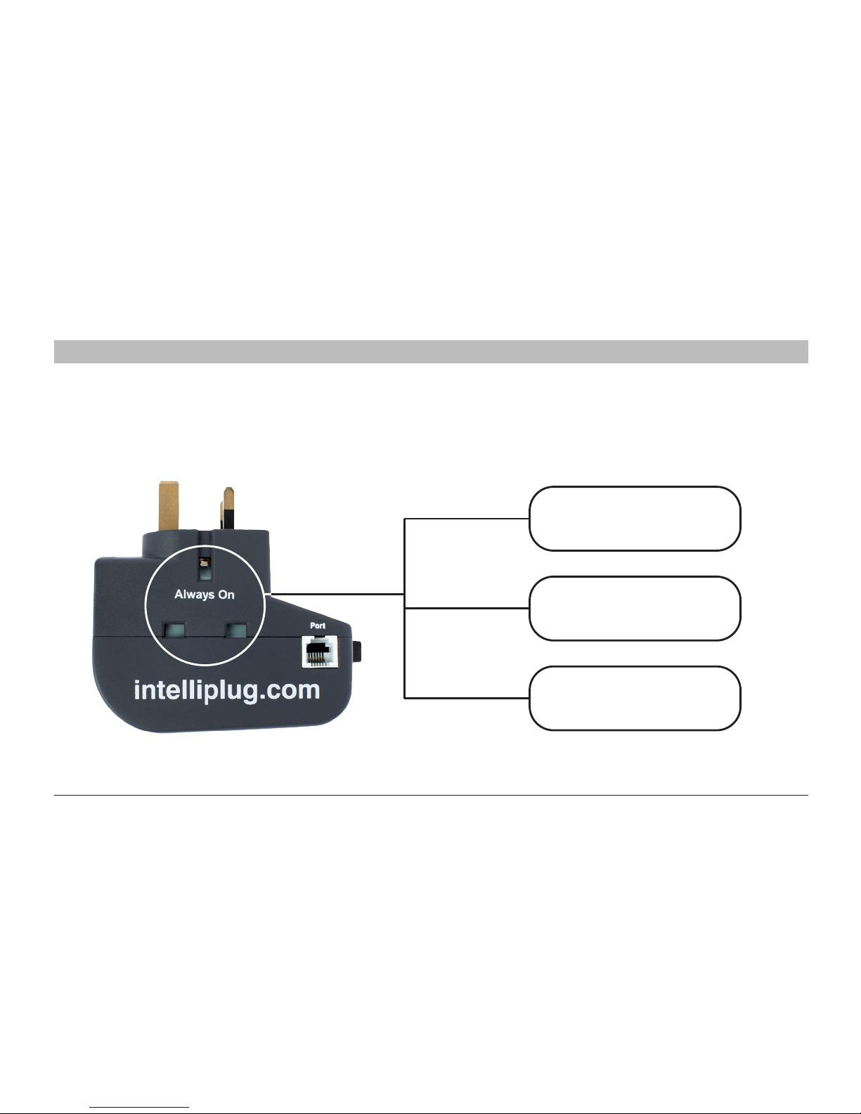
Step 7 Use always on socket on the One Click IntelliPlug to connect items that require continuous power
such as hard-disk, video, or DVD recorders.
Hard Disc Recorder
Video Recorder
DVD Recorder
Page 17
15
Dual Mode IntelliPlug AVC014
SECTION
Tab le of C ontents
1
2
3 4 5
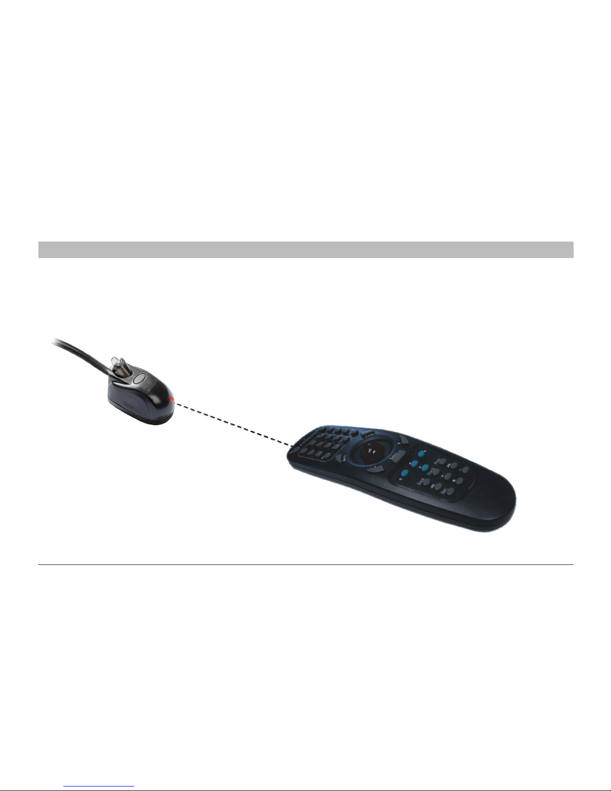
Step 1 Use any infrared remote control by pointing it at the Remote Sensor and pressing any button.
Power will be applied to your television for approximately 20 seconds.
OPERATING THE INTELLIPLUG WITH THE REMOTE SENSOR
Remote Sensor
Page 18
16
Dual Mode IntelliPlug AVC014
SECTIONS
Tab le of C ontents
1
2
3 4 5
Step 2
Within 20 seconds press the power button on your
television remote control to bring your television out of
standby, enjoy your television in the normal manner
and send power to your peripheral equipment.
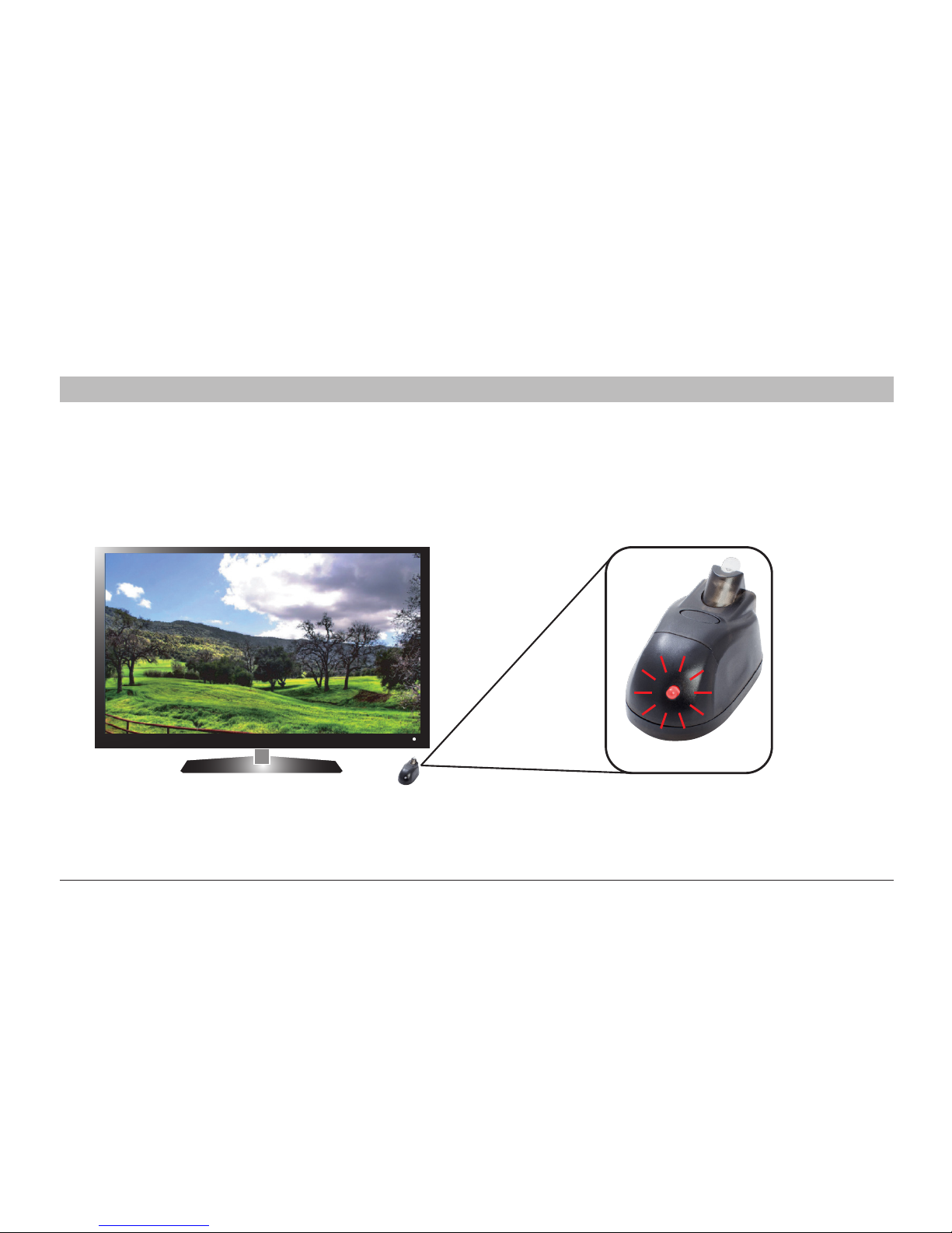
Step 3
The Remote Sensor LED will flash red every time it
receives an infrared signal from any remote control.
OPERATING THE INTELLIPLUG WITH THE REMOTE SENSOR
Remote Sensor
INSTALLATION COMPLETE
Page 19
17
Dual Mode IntelliPlug AVC014
SECTIONS
Tab le of C ontents
1
2
3 4 5
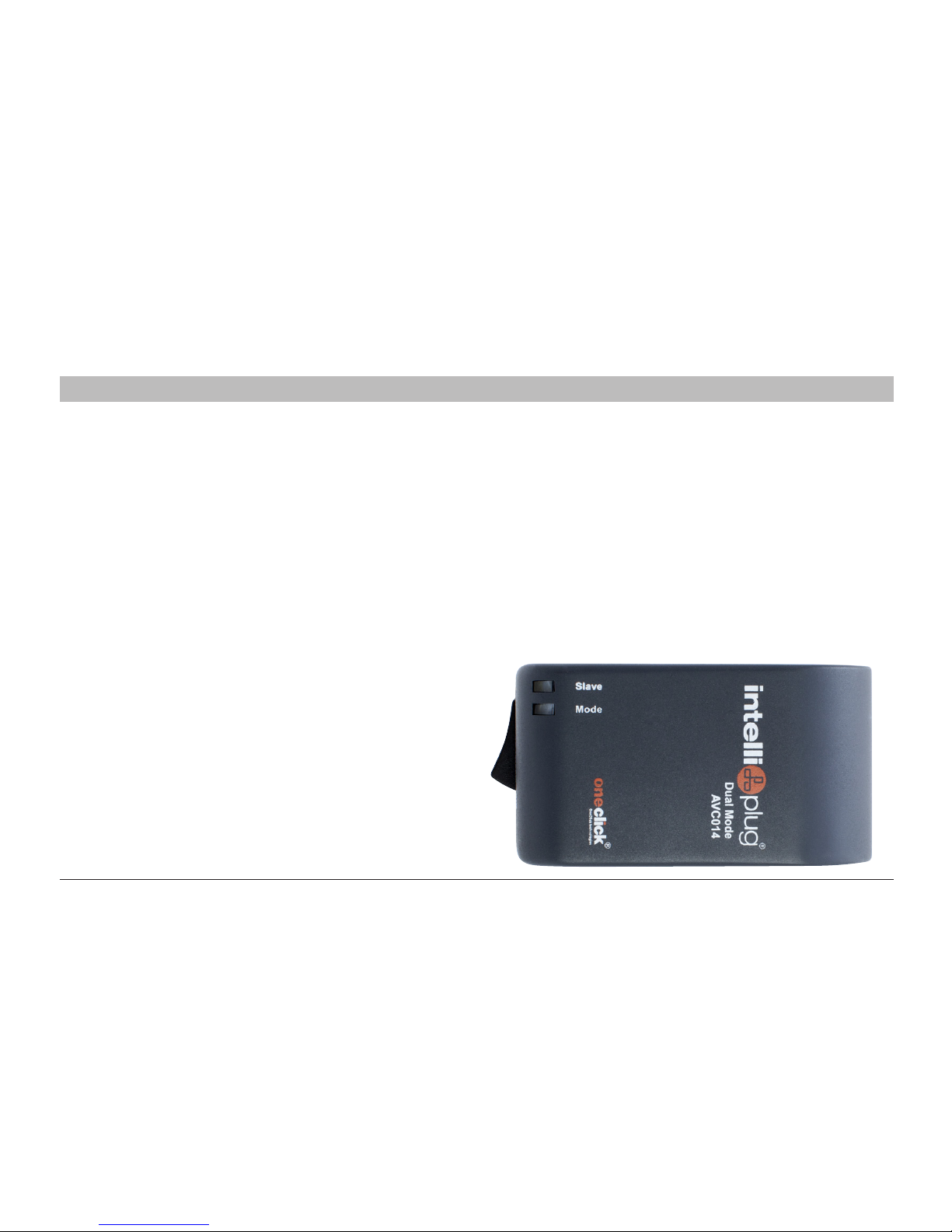
LED Indicator Lights - Infra Red Mode
The Mode LED will glow GREEN when the One Click
IntelliPlug is receiving power from the mains.
The Slave LED will glow RED if the Remote Sensor has
not been connected.
Once the Remote Sensor is connected and power is
switched to peripheral equipment, the LED will glow
GREEN.
During the shutdown process, the LED will flash GREEN
for approximately 5 minutes before power is shut down.
If there are no
LEDs illuminating on the unit, ensure the unit
is connected properly to the mains power point and the mains
power switch is turned on at the wall.
If the wall socket is set to ON, then disconnect the One Click
IntelliPlug from the wall socket and then plug it back in.
Try connecting the One Click IntelliPlug on another wall socket.
Failing that, navigate to our support pages on how to obtain
a replacement unit
OPERATING THE INTELLIPLUG WITH THE REMOTE SENSOR
Page 20
18
Dual Mode IntelliPlug AVC014
SECTIONS
Tab le of C ontents
1
2
4 5
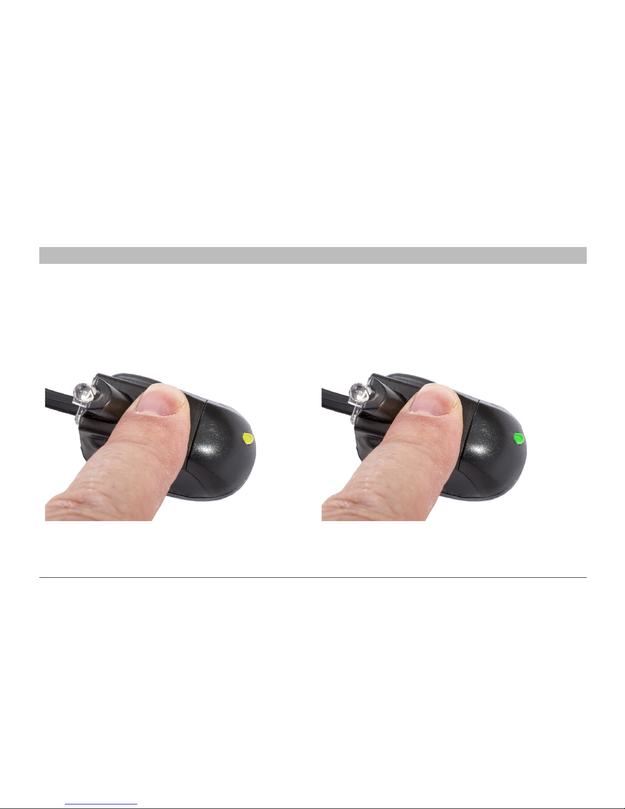
Step 4 - Optional Remote Control Paring
The REMOTE SENSOR is capable of being paired to your remote control which prevents other remote controls,
lighting or sunlight unintentionally triggering the IntelliPlug into standby mode. Position your television remote control in
line with the SENSOR as illustrated on page 15. Ensure that the IntelliPlug is plugged into the mains and the power is on.
OPERATING THE INTELLIPLUG WITH THE REMOTE SENSOR
1.
3.Press and release the remote control power button a second time. The Sensor responds by the front LED
FLASHING YELLOW THEN GREEN ONCE.
4.Press and release the remote control power a third time. The LED will illuminate GREEN for 3 seconds then extinguish.
2.
Press and HOLD DOWN the button on the Sensor.
The Front LED will illuminate RED and the IntelliPlug
will temporarily activate, then the front LED starts to
FLASH YELLOW FAST
Press and Release the Power button on the Remote
Control. The Sensor LED responds by turning GREEN
Wait until the Green LED illuminates every few seconds
then release the button on the Sensor
SECTIONS
Tab le of C ontents
1
2
3 4 5
Page 21

A. Point your remote control at the Sensor and press the POWER-ON button, the REMOTE SENSOR will flash GREEN
every time it receives a command from your remote control. Your television should now be activated into standby mode.
If, at this stage, your television receives a picture, go to C below
B. Use your remote to switch your television onto any available channel, once you see the television is active
and you have a picture on the screen please proceed to the next step.
C. Use your remote control to switch your television off into standby mode. Power to the television and peripherals
will be cut when your television reaches a low power state, between approximately 20 seconds and 10 minutes
but may take longer in some instances.
Advanced Installation Mode
You may elect to use both the television and A/V amplifier as master devices. You must use a trailing socket to connect
to the Master Socket on the IntelliPlug and then connect the television and amplifier to the trailing socket.
DO NOT USE A 2 OR 3 WAY ADAPTER directly into the IntelliPlug.
Pairing a second Remote Control
Repeat the procedure on page 18 using the A/V remote but in stage 3, once you have released the remote sensor,
(GREEN LED is flashing once every few seconds) press and release the sensor button again.
The GREEN LED will then flash TWICE every few seconds. Then continue to complete stage 3 and 4.
Reprogramming The Sensor
To reprogram the REMOTE SENSOR you must first clear the memory. Simply PRESS and HOLD the SENSOR BUTTON
for approximately 60 seconds until the LED starts to flash RED, then release.
19
Dual Mode IntelliPlug AVC014
SECTIONS
Tab le of C ontents
1
2
3 4 5
OPERATING THE INTELLIPLUG WITH THE REMOTE SENSOR
Page 22

20
Dual Mode IntelliPlug AVC014
SECTIONS
Tab le of C ontents
1
2
3 4 5
Optional Timer Facility
The Remote Sensor has a built in timer that can automatically switch power off from your television and peripheral
equipment. A few minutes prior to powering off your equipment, the LED in the Remote Sensor will flash RED slowly
and then steadily increase to bursts of 3 flashes prior to shutting down the power. To cancel the process, point your
infrared remote control at the Remote Sensor and press any button. The time-out period will be reset. The timer can
be changed from the default setting, which is OFF, to 1, 2, 3 or 4 hours.
Step 5 - Setting the Auto Shutdown Timer
To set up the delay timer for 1, 2, 3, or 4 hours:
1. Press and hold the button on the Remote Sensor and the LED will illuminate RED. After approximately 15 seconds
the LED will flash yellow rapidly for a few seconds and then flash in bursts of 5 flashes to indicate the
current default setting which is OFF.
2. Release the button-the LED will continue to flash yellow in burst of 5 flashes for about 30 seconds.
3. If the button is pressed and released again within 30 seconds, the next time sequence will be selected.
This will be indicated by the LED flashing the appropriate number of times and then off for a time before repeating
(1 to 4 flashes representing hours delayed or 5 flashes for OFF).
4. After about 30 seconds the flashing will stop indicating the delay timer value has been set.To continue using your
equipment, simply press any button on your remote control or press the button on the Remote Sensor.
Hard Timer Shutdown
This type of shutdown occurs when the television remote control is not paired to the Remote Sensor. The power
to your television and peripheral equipment is switched off without first switching the television into STANDBY.
Soft Timer Shutdown
Pairing your television remote is the perfect solution to enhance the performance and life-span of your equipment.
By carefully positioning the INFRA-RED part of the Remote Sensor in front of the INFRA-RED receiver of the television
(see page 13), the IntelliPlug will place the television into standby mode when the pre-set timer period expires.
When the television has returned to its quiescent state, the power is disconnected.
OPERATING THE INTELLIPLUG WITH THE REMOTE SENSOR
Page 23

21
Dual Mode IntelliPlug AVC014
SECTION
Tab le of C ontents
1
2
3 4 5
Congratulations
You have successfully programmed your IntelliPlug.
To use your television, point your remote control at the sensor and press the POWER ON button.
Your television will be activated into standby mode so continue to use your remote as normal.
If you lose your remote control you can activate power to your television and peripherals by briefly pressing the Sensor button.
Optional Accessories:
Programming and Interrogation Cable
This connects the AVC014 IntelliPlug to a Windows PC via a special USB / RJ12 cable, adapter and software.
This facilitates:
Easy programming of remote controls
Choosing and storing timer options
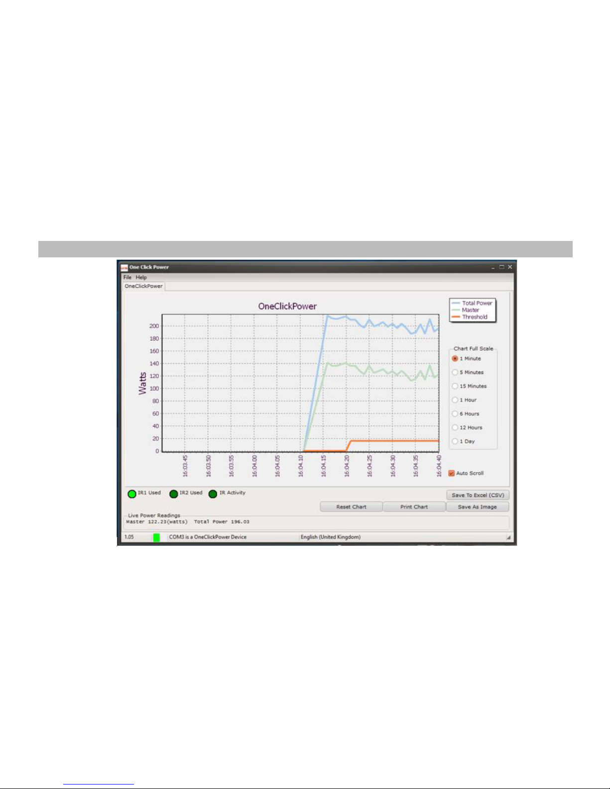
Interrogation of power usage of both Master and Peripheral connected equipment (see page 29)
For further information please visit www.oneclickpower.com
OPERATING THE INTELLIPLUG WITH THE REMOTE SENSOR
Page 24

FREQUENTLY ASKED QUESTIONS for the INTELLIPLUG WITH THE REMOTE SENSOR
What AV devices can I connect to my IntelliPlug?
The IntelliPlug is compatible with all AV devices.
Can I use an alternative cable to connect the
One Click IntelliPlug
to the Remote Sensor?
No, you must use the cable supplied.
The red LED on my television stays on for several
minutes before disappearing. Is this normal?
The One Click IntelliPlug waits until your television is
fully switched off and has completed its internal
powering down before switching off
the power.
Will the One Click IntelliPlug operate without the
Remote Sensor attached?
With the mode switch in the infra red position
the One Click IntelliPlug will not operate without the
Remote Sensor connected via the supplied cable.
If you remove the Remote Sensor during operation,
the One Click IntelliPlug will not be able to complete
the shutdown process.
Can I use the One Click IntelliPlug if I misplace
my remote control?
Simply press the button on the remote sensor, power will then
be restored to your television. To reset the countdown timer,
sim
ply press the button on the remote sensor.
What do the LEDs on the One Click IntelliPlug indicate?
Mode LED will glow GREEN when the One Click IntelliPlug is
receiving power from the mains. Slave LED will glow RED if
the Remote Sensor has not been connected.
Once the Remote Sensor is connected and power is switched
to peripheral equipment, the LED will glow GREEN.
During the shutdown process the LED will flash GREEN for
approximately 5 minutes before power is sh
ut down.
None of the LEDs are working on my One Click IntelliPlug?
Ensure that the wall socket switch is set to the ON position.
22
Dual Mode IntelliPlug AVC014
SECTION
Tab le of C ontents
1
2
3 4 5
Page 25

TROUBLESHOOTING for the INTELLIPLUG WITH THE REMOTE SENSOR
My One Click IntelliPlug does not power on.
Ensure the unit is connected properly to the mains
power point and the mains power switch is turned
on at the wall and/or the power board.
Disconnect the adapter from the wall socket and
then plug it back in.
If the adapter still fails to work, try the IntelliPlug in
another wall socket.
My One Click IntelliPlug does not power off my
connected devices in standby mode
Ensure the devices are plugged into the slave socket
and
not the master socket.
There has been no detection of any change in power
consumption from your connected devices.
The Remote Sensor has not detected any infrared
activity. Turn ON the connected devices and wait 30
seconds and switch these devices OFF again.
Ensure you are using an infrared (IR) remote and not
a wireless remote such as Bluetooth
® or
2.4GHz radio frequency control.
The Remote Sensor intermittently flashes d
uring use
There may be unusual infrared activity in the range of your
connected devices. Please check the area for any infrared
devices that may be interfering with the Remote Sensor.
Relocate the position of the Remote Sensor near any of
your connected devices that are under normal operating
remote controls.
My Remote Sensor is not working but the LEDs on the
One Click IntelliPlug are working
Ensure that the supplied RJ12 cable is connec
ted properly
to the One Click IntelliPlug and the Remote Sensor.
Disconnect and reconnect, both ends, of the supplied
RJ12 cable. When you reconnect the Remote Sensor,
check that it shows a green LED.
Press and hold the button on the Remote Sensor for 1
second when the RJ12 cable is connected securely.
The LED should flash red and you will hear the IntelliPlug
click when it switches on.
If the LED does not work and the IntelliPlug does not
turn on, then the Rem
ote Sensor and/or units are faulty.
23
Dual Mode IntelliPlug AVC014
SECTIONS
Tab le of C ontents
1
2
3 4 5
.
Page 26
24
Dual Mode IntelliPlug AVC014
SECTION
Tab le of C ontents
1
2
3 4 5
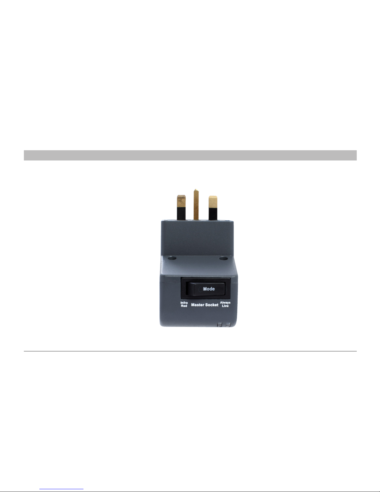
Step 1 Make sure that the One Click IntelliPlug Master Socket Mode switch is set to Always Live
INSTALLATION - DESKTOP / LAPTOP COMPUTER CONFIGURATION
Do not use the Remote Sensor or RJ12 cable
in this recommended configuration
Power is always on to the Master Device
Power to peripheral equipment is switched on
when the computer is in use
Power to peripheral equipment is denied
when the desktop computer is switched off
or, if used with a laptop, when the laptop
battery is fully charged.
For additional configuration ideas / information
visit www.oneclickpower.com
Page 27
25
Dual Mode IntelliPlug AVC014
SECTION
Tab le of C ontents
1
2
3 4 5
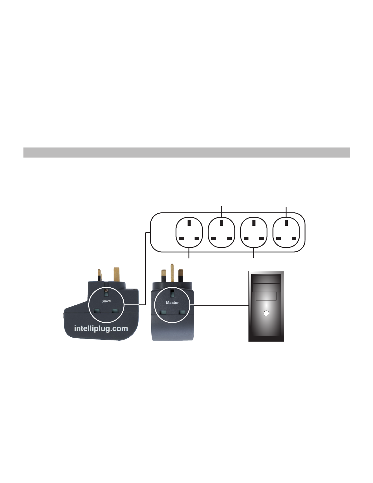
Step 2 Connect your Desktop or Laptop Computer to the Master Socket and connect peripheral equipment via a
power distribution panel (not supplied) to the One Click Intelliplug as illustrated below.
INSTALLATION - DESKTOP / LAPTOP COMPUTER CONFIGURATION
Printer Lamp
SpeakersMonitor
Page 28
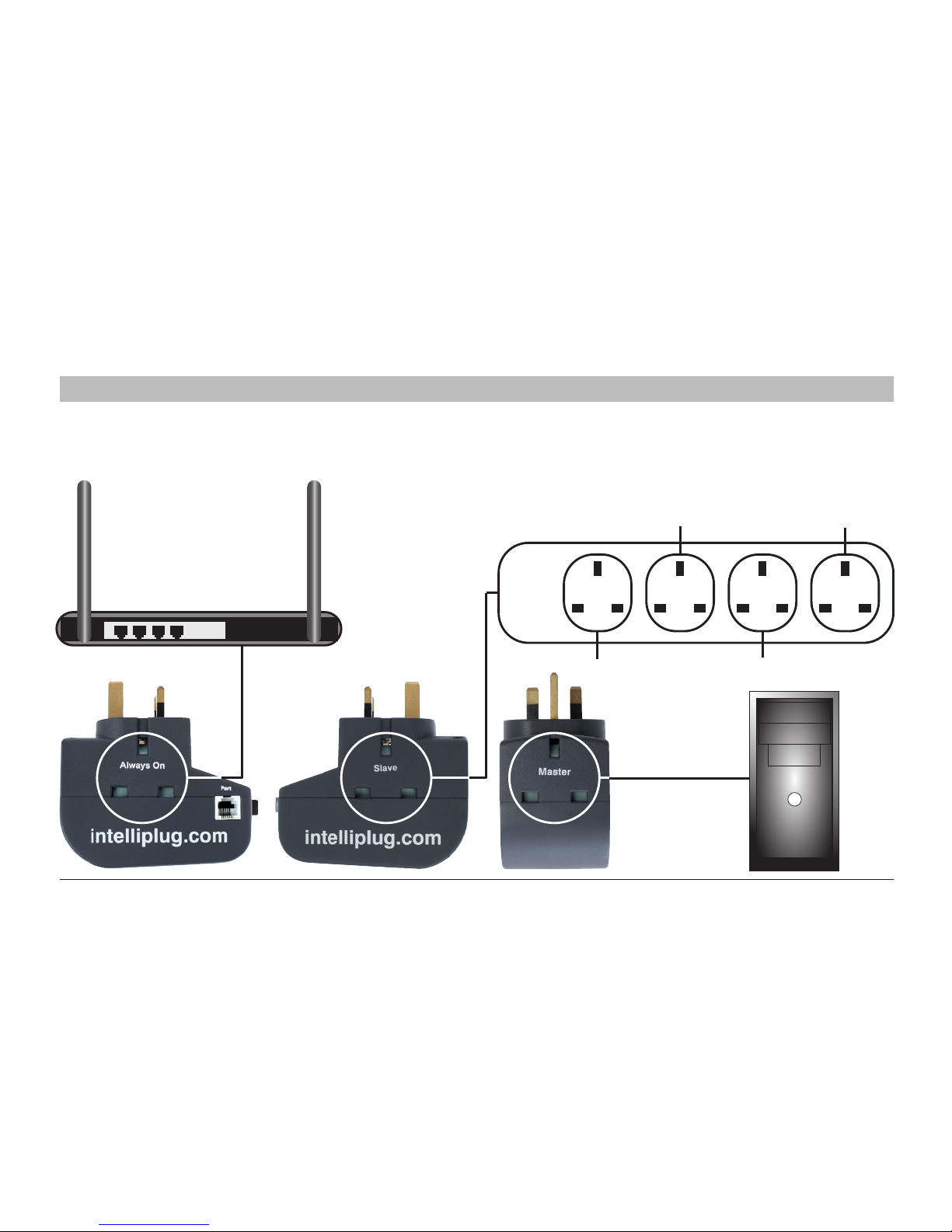
Printer Lamp
SpeakersMonitor
Wi Fi Hub
26
Dual Mode IntelliPlug AVC014
SECTION
Tab le of C ontents
1
2
3 4 5
Step 3 Connect items that require continious power such as a router, modem or wi-fi hub to the always on socket
on the One Click Intelliplug as illustrated below.
INSTALLATION - DESKTOP / LAPTOP COMPUTER CONFIGURATION
Page 29
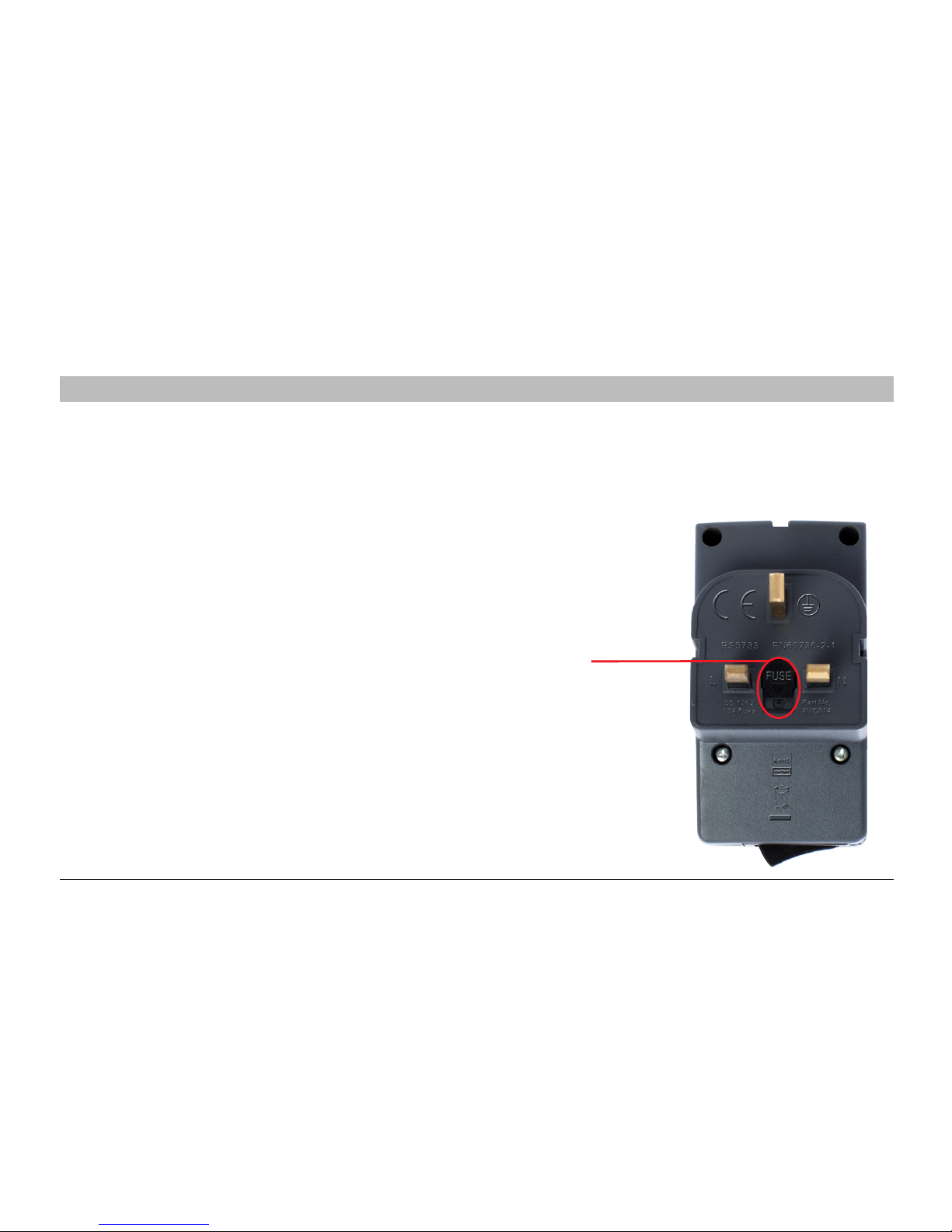
FUSE HOLDER
27
Dual Mode IntelliPlug AVC014
SECTION
Tab le of C ontents
1
2
3 4
My One Click IntelliPlug unit does not work anymore.
.
• Disconnect all devices from the One Click IntelliPlug
unit and unplug the unit from the wall socket.
Plug the One Click IntelliPlug into the wall socket and
check the Slave LED to see that it’s green. If the LED
is green, then reconnect the devices to the unit.
• If the LED is not green, then try another power socket.
• Check the 13 amp fuse, replace if necessary
5
FREQUENTLY ASKED QUESTIONS - DESKTOP / LAPTOP CONFIGURATION
What do the LEDs indicate in Desktop / Laptop Configuration?
Operational Mode LED will illuminate GREEN when the Intelliplug is recieving power from the mains.
Once power is switched to peripheral equipment the Slave Status will illuminate GREEN.
During the shutdown process the Slave Status LED will flash GREEN then go off.
None of the LEDs are working on my One Click Intelliplug.
Ensure that the wall socket is set to the ON position.
Page 30

28
Dual Mode IntelliPlug AVC014
INFORMATION
SECTION
Tab le of C ontents
1
2
3 4 5
One Click Technologies Limited, Limited 1-Year Product Warranty.
What this warranty covers..
One Click Technologies Limited (“One Click”) warrants
to the original purchaser of this One click product that
the product shall be free of defects in design, assembly,
material, or workmanship.
What the period of coverage is.
One Click warrants the OneClick product for one (1) year.
.
What will we do to correct problems?
Product Warranty.
One Click will repair or replace, at its option, an
y
defective product free of charge (except for shipping
charges for the product). One Click reserves the right to
discontinue any of its products without notice, and
disclaims any limited warranty to repair or replace any
such discontinued products. In the event that One Click
is unable to repair or replace the product (for example,
because it has been discontinued), One Click will offer
either a refund or a credit toward the purchase of another
product
from One Click in an amount equal to the purchase
price of the product as evidenced on the original purchase
receipt as discounted by its natural use.
What is not covered by this warranty?
All above warranties are null and void if the One Click
product is not provided to One Click for inspection upon
One Click’s request at the sole expense of the purchaser,
or if One Click determines that the One Click product has
been improperly installed, altered in any way, or ta
mpered
with. The One Click Product Warranty does not protect
against acts of God such as flood, lightning, earthquake,
war, vandalism, theft, normal-use wear and tear, erosion,
depletion, obsolescence, abuse, damage due to low
voltage disturbances (i.e. brownouts or sags),
non-authorized program, or system equipment
modification or alteration.
Page 31
29
Dual Mode IntelliPlug AVC014
One Click Power Monitor Application Dialogue Window - Optional Upgrade
SECTION
Tab le of C ontents
1
2
3 4 5
For more information and to purchase software with a USB/RJ12 connection cable please go to www.oneclickpower.com
Page 32

30
Dual Mode IntelliPlug AVC014
INFORMATION
SECTION
Tab le of C ontents
1
2
3 4 5
Declaration of Conformity
One Click Technologies Limited
Registered Office:
Rosemount, Juniper Lane, Wooburn Green, High Wycombe, Buckinghamshire HP10 0DE ENGLAND
Declare under our responsibility the electrical product:
IntelliPlug AVC014
Intelligent Mains Plug
To which this declaration relates, is in conformity with the following standards:
EN 60730-2-1 : 1997
( In conjunction with EN 60730-1 :1995
+A1+A2+A13+A14+A15+A12+A11+A16+A17)
Automatic electrical controls for household and similar use-
Part 2-1: Particular requirements for electrical controls for
electrical household appliances
Test Report Number(s) : 14010589HKG-002
Date of Tests : 15 Jan 2014 to 05 May 2014
Low Voltage Directive (2006/95/EC)
Electromagnetic Compatibility Directive (89/336/EEC)-EMC
This product carries the CE Mark, which was affixed on the 12th of May 2014
Signed:
Peter S. Robertson
Managing Director
Page 33

© 2016 One Click Technologies Limited All rights reserved. All trade names are registered trademarks of respective manufacturers listed.
Version 1.5.0.0
www.oneclickpower.com
 Loading...