

Page 1

ONECell25
Installation Manual
February 2009
http://www.oneaccess-net.com
Page 2

OneAccess
28 rue de la Redoute
92260 Fontenay aux Roses
France
The law of 11 March 1957, paragraphs 2 and 3 of article 41, only authorizes, firstly,
’copies and reproductions strictly reserved for use by copyists and not for general
use and, secondly, analyses and short quotations for the purpose of example and
illustration. Therefore, ’any representation or reproduction, entire or partial, made
without the consent of the author or his representatives is illegal’ (paragraph 1 of
article 40).
Any such representation or reproduction, made in any manner whatsoever, would
therefore constitute an infringement of the law as sanctioned by articles 425 and in
accordance with the penal code.
Information contained in this document is subject to change without prior notice and
does not constitute any form of obligation on the part of OneAccess.
OneAccess and the distributors can in no case be held responsible for direct or
indirect damage of any kind incurred as a result of any error in the software or
guide.
Every care has been taken to ensure the exactitude of information in this manual. If
however you discover an error, please contact OneAccess After Sales Service
division.
February 2009 Issue
2
ONECELL25 - Installation Manual
Page 3

How to Read this Manual
The present document is broken down into 7 chapters.
Chapter 1 – Safety Instructions
This chapter provides the safety instructions for use and installation of the router.
Chapter 2 – Directives and Standards
This chapter details the list of standards, which the device complies with.
Chapter 3 – Router Description
This section describes the router front and rear panels and the associated techn ical
characteristics.
Chapter 4 – Interface Description
This section describes the router interfaces.
Chapter 5 – Technical Characteristics
This section describes technical characteristics such as operating conditions.
Chapter 6 - Installation
This chapter describes how to install SIM card and gives instructions to connect the
router.
Chapter 7 – Power-up
This chapter describes the device power-up and how to monitor the self-test
progress.
Chapter 8 – Getting Started
This chapter explains to connect to the web Configurator and main oper ations with
the product.
Appendix – Connection des cription
These chapters provide the pin-out of cables that are compatible with the router.
3
ONECELL25 - Installation Manual
Page 4

Table of Contents
How to Read this Manual ........................................................................................................................3
Table of Contents ....................................................................................................................................4
1 Safety Instructions ........................................................................................................................5
1.1 Connection to Power Supply...................................................................................................5
1.2 Overcurrent Protection ............................................................................................................5
1.3 Safety Level of Interfaces........................................................................................................5
2 Directives and Standards..............................................................................................................7
2.1 Declaration of Conformity........................................................................................................7
2.2 Standards................................................................................................................................8
3 Router Description........................................................................................................................9
3.1 Hardware Description..............................................................................................................9
3.2 Front Panel..............................................................................................................................9
3.3 Rear Panel ............................................................................................................................11
3.4 Motherboard..........................................................................................................................11
4 Interface Description...................................................................................................................13
4.1 LAN 10/100 Mbps Interface (FASTETHERNET)...................................................................13
4.2 Console port (CONSOLE).....................................................................................................14
5 Technical Characteristics............................................................................................................15
5.1 Climatic Environment ............................................................................................................15
5.2 Power Supply ........................................................................................................................15
5.3 Dimensions............................................................................................................................15
6 Installation...................................................................................................................................16
6.1 Opening Casing.....................................................................................................................16
6.2 Installing SIM Card................................................................................................................17
6.3 Wall Mounting........................................................................................................................19
6.4 Connections ..........................................................................................................................20
7 Power up.....................................................................................................................................21
8 Getting Started............................................................................................................................22
8.1 Connect your PC...................................................................................................................22
8.2 Starting the Web Configurator...............................................................................................22
8.3 Restoring Factory Settings....................................................................................................23
8.4 Configuration by Telnet / SSH / Console...............................................................................23
8.5 Getting Support on ONECELL25 ..........................................................................................23
Appendix A - Console Cable .................................................................................................................24
4
ONECELL25 - Installation Manual
Page 5

1 Safety Instructions
The following symbol instructs the user to read the manual carefully before any
connection:
1.1 Connection to Power Supply
To connect the power supply, always follow these steps:
• Connect the DC input jack from the power supply to the DC 12V power input
on the rear panel of the router,
• Connect the power supply to an AC electrical outlet (200-240 VAC). Plugging
in the power supply turns on the router.
Unplug the AC input before assembling/disassembling any part on the
device. The AC input is the part you must disconnect first. For safety reasons, you shall be able to easily access this part.
1.2 Overcurrent Protection
The product requires that the building’s electrical installation is designed for
protection against short-circuit (over current) protection.
A fuse or circuit breaker no larger than 2 40 VAC, 10A must be used on the phase
conductors.
1.3 Safety Level of Interfaces
1.3.1 LAN Interface 10/100 Mbps (FASTETHERNET)
This section is related to interfaces whose marking on the router back panel is:
FASTETHERNET.
The Ethernet 100 Mbps auto-sense has a ’SELV’ (Safety Extra Low Voltage)
interface.
They must be used only for i ndoor applicati ons, connected to a 100 Mbps interface,
which has also the ’SELV’ characteristics.
5
ONECELL25 - Installation Manual
Page 6

The Ethernet interfaces of the ONECell25 only support the 100 Mbps fullduplex operations in auto-sense mode. If connected to devices in 10 mbps
or half-duplex, the ONECell25 interface will not be connected. The problem
can appear mostly with devices forced in such mode or with old Ethernet
hub.
1.3.2 V.24 Interface (CONSOLE)
This sections is related to the interface whose marking o n the router back panel is:
CONSOLE
The interface is SELV. It must be used only for in door appli cations and co nnecte d t o
V.24 interfaces, which are also designed as ’SELV’.
1.3.3 GSM Antenna
The antenna used for this transmitter must be installed to provide a separation
distance of at least 20 cm from all persons and must not be co-located or operating
in conjunction with any other antenna or transmitter.
6
ONECELL25 - Installation Manual
Page 7

2 Directives and Standards
s
l
l
r
r
y
_
2.1 Declaration of Conformity
Déclaration de conformité suivant les directives R&TTE, DBT et CEM
Declaration of Conformity according to R&TTE, LVD and EMC directives
ONE_CELL25
Routeur et adaptateur de réseau / Router and network adapter
Tension d’alimentation / Supply voltage : 200-240 Vac, 20 W, 50-60 Hz (12V – 1A)
Nous déclarons que ce produit es t présumé conforme aux exigenc es essentielles applicables des directive
suivantes du Parlement Européen et du Conseil :
- la Directive R&TTE 1999/5/CE, du 9 mars 1999, concernant les équipements hertziens et les
équipements terminaux de télécommunications et la reconnaissance mutuelle de leur conformité;
- la Directive Basse Tension 2006/95/EC du 12 décembre 2006 concernant le rapprochement des
législations des Etats Mem bres relatives au matériel électr ique destiné à être employé dans certaines
limites de tension;
- la Directive CEM 2004/108/EC du 15 décembre 2004 relative au rapprochement des législations des
États membres concernant la compatibilité électromagnétique et abrogeant la directive 89/336/CEE.
We declare that this product has been given a presumption of conformity with the applicable essentia
requirements of the following directives of the European Parliament and of the Council :
- R&TTE Directive 1999/5/EC of march 9
equipment and the mutual recognition of their conformity ;
- Low Voltage Directive 2006/95/EC of december 12
States relating to electrical equipment designed for use within certain voltage limits;
- EMC Directive 2004/108/EC of december 15
States relating to electromagnetic compatibility and repealing Directive 89/336/EEC.
th
1999, on radio equipment and telecommunication termina
th
2006, on the harmonization of the laws of Membe
th
2004, on the approx imation of the laws of the Membe
Nous déclarons que les norm es harmonisées suivant es ont été utilisées pour dé montrer cette présom ption de
conformité et ont donné lieu aux rapports de tests suivants, disponibles sur demande.
We declare that the followi ng harmonised stand ards were use d to demonstrate this presumption of confor mit
and the results are included in the following tests reports, which can be made available on request.
EN/IEC 60950-1 (2001) – First Edition
EN 55022 (1998)
EN 55024 (1998)
EN 300511 (1995-07)
EN 301489-1 (2007-04)
EN 301489-7 (2005-11)
Laboratoire GYL Technologie pour la Sécurité / GYL Technologie for Safety.
Laboratoire Gyl Technologie pour CEM / Gyl Technologie Laboratory for EMC.
Le produit est marqué du symbole « CE » en application des directives citées ci-dessus.
The product is marked with the « CE » symbol in accordance with the directives mentionned above.
Responsable autorisé / Authorized signatory Directeur Général / Chief Operating Officer
_______________________________
Nom / Name : Denis BEHAGHEL
7
ONECELL25 - Installation Manual
Page 8
2.2 Standards
The ONECell25 is designed in conformity with the standards listed hereafter,
provided that the basic housing, modules, interface boards and installati on kits are
mounted as recommended in the corresponding installation manu al(s).
Safety
EN/IEC 60950-1: 2001,
First Edition
Safety of information technology equipment, including electrical
business equipment.
Environment:
Climatic, physico chemical, mechanic, packing
ETS 300 019-1 Environmental conditions and environmental testing for
telecommunication equipment
In use : Class 3.1- Temperature controlled locations
Storage : Class 1.1 - Weather protected, partly temperature
controlled storage locations
Transportation : Class 2.3 – Public transportation
Electromagnetic Compatibility, immunity
EN 55022 Information technology equipment – Radio disturbance
characteristics- Limits and methods of measurement
EN 55024 Information technology equipment - Immunity characteristics -
Limits and methods of measurement
EN 301 511 Harmonized EN for mobile stations in the GSM 900 and GSM 1800
bands covering essential requirements under article 3.2 of the
R&TTE directive (1999/5/EC)
EN 301 489-01 ElectroMagnetic Compatibility (EMC) standard for radio equipment
and services; Part 1: Common technical requirements
EN 301 489-07 ElectroMagnetic Compatibility (EMC) standard for radio equipment
and services; Part 7: Specific conditions for mobile and portable
radio and ancillary equipment of digital cellular radio
telecommunications systems (GSM and DCS)
Waste Electrical and Electronic Equipment
2002/96/EC The ONECell25 respects the European directive on the waste
disposal from the electrical and electronics components.
Restricted use of Hazardous Substances (RoHS)
2002/95/EC The ONECell25 respects the European directive on the restricted
use of Hazardous Substances in electric and electronic equipment.
8
ONECELL25 - Installation Manual
Page 9
3 Router Description
3.1 Hardware Description
3.1.1 Motherboard Interfaces
The ONECell25 motherboard is equip ped wit h the follo wing interfaces. T he interface
marking is indicated in bold and between brackets.
• 1 console port (CONSOLE),
• 2 Ethernet port (LAN 100 BT) (FASTETHERNET)
The Ethernet interfaces of the ONECell25 only support the 100 Mbps fullduplex operations in auto-sense mode. If connected to devices in 10 mbps
or half-duplex, the ONECell25 interface will not be connected. The problem
can appear mostly with devices forced in such mode or with old Ethernet
hub.
3.2 Front Panel
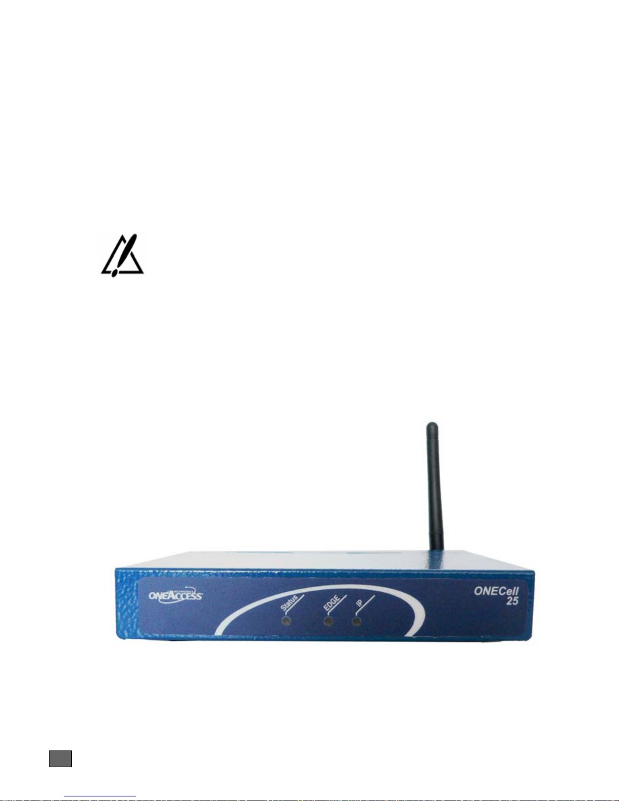
The front panel is provided with LEDS, which inform about the status of several
router functions.
9
Figure 1. Front panel
ONECELL25 - Installation Manual
Page 10

Leds OFF Green Blinking green
Status Router is
switched Off
EDGE Not configured
or connection
not established
Switched On &
Operational
EDGE/GPRS
connection
established
IP Not used All IP interfaces are
up
Reboot in
progress
Traffic on
EDGE/GPRS
At least one IP
interface is down
10
ONECELL25 - Installation Manual
Page 11
3.3 Rear Panel
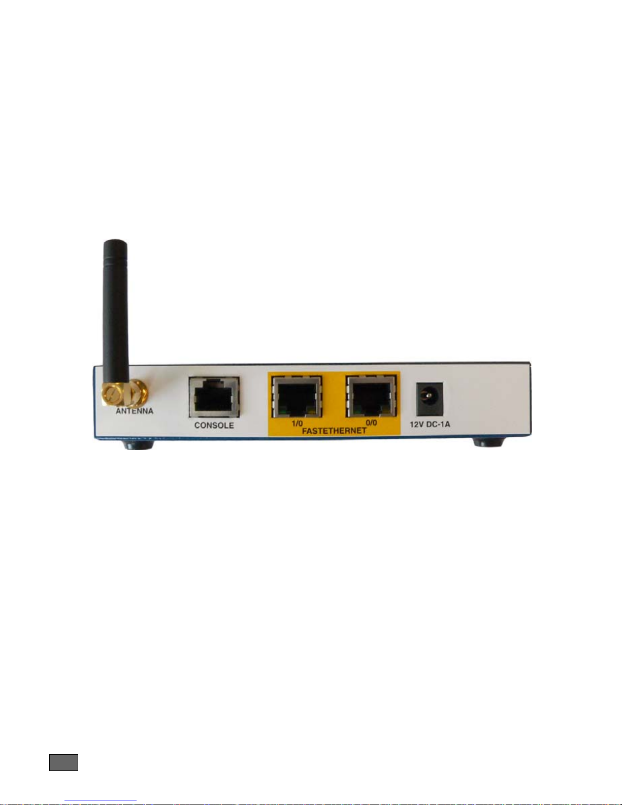
This section details the various types of ONECell25 rear panel so that the user can
identify the interface type and port numbering.
The interface marking is indicated in bold and bet ween br acket.
All the connectors are located on the rear panel:
• 1 console port (RJ45) (CONSOLE),
• 2 Ethernet ports (RJ45) (FASTETHERNET 1/0 and FASTETHERNET 0/0),
• 1 connectors for GSM antenna (ANTENNA),
• Input for the external po wer supply connector (DC input jack, 12V-1A).
3.4 Motherboard
The motherboard provides:
• Router resources (CPU, DSP, memor y RAM and Flas h),
• Standard router interfaces (console interface, Fast Ethernet, and LEDs),
• An EDGE/GPRS radio module supporti ng a SIM card
Figure 2. Rear panel
11
ONECELL25 - Installation Manual
Page 12
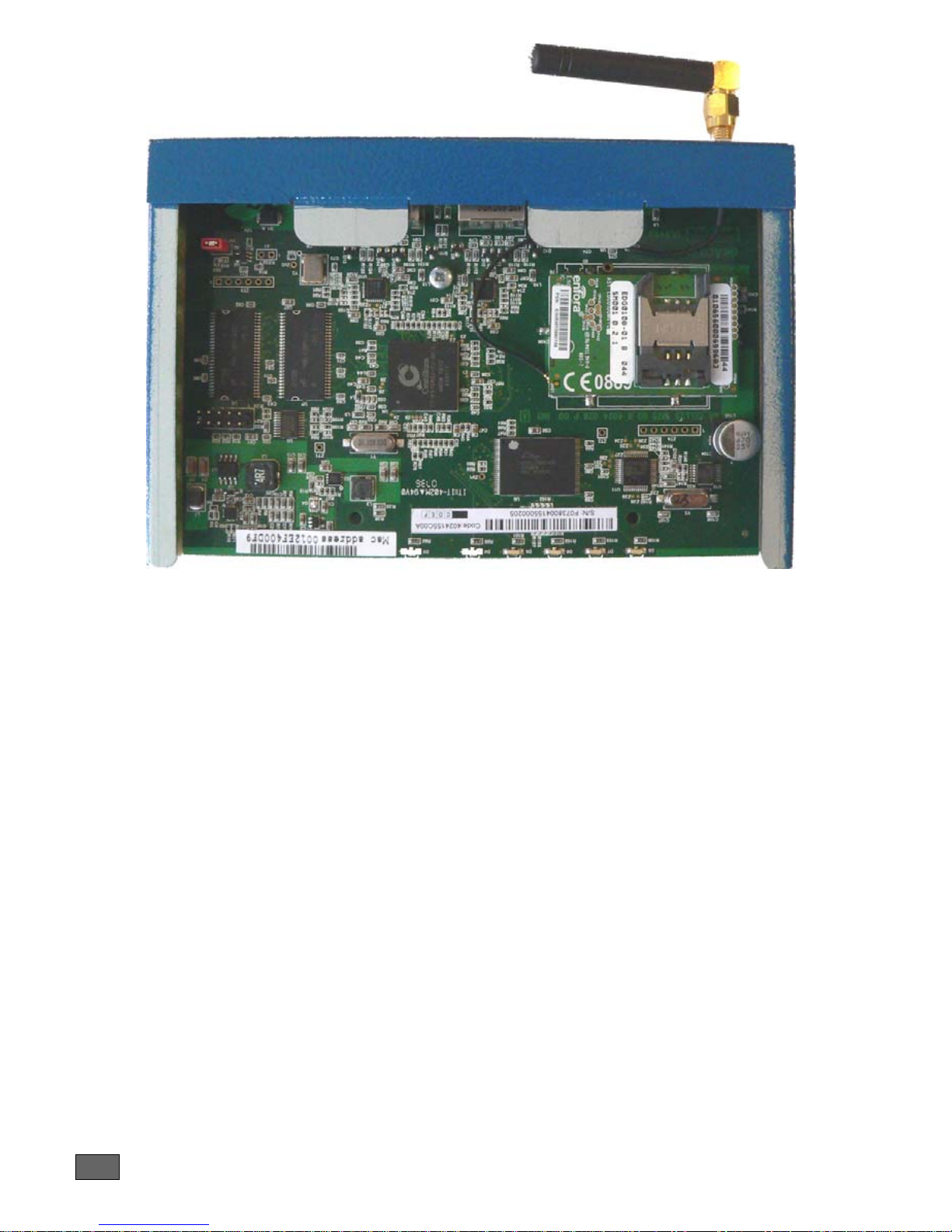
Figure 3. Motherboard
12
ONECELL25 - Installation Manual
Page 13
4 Interface Description
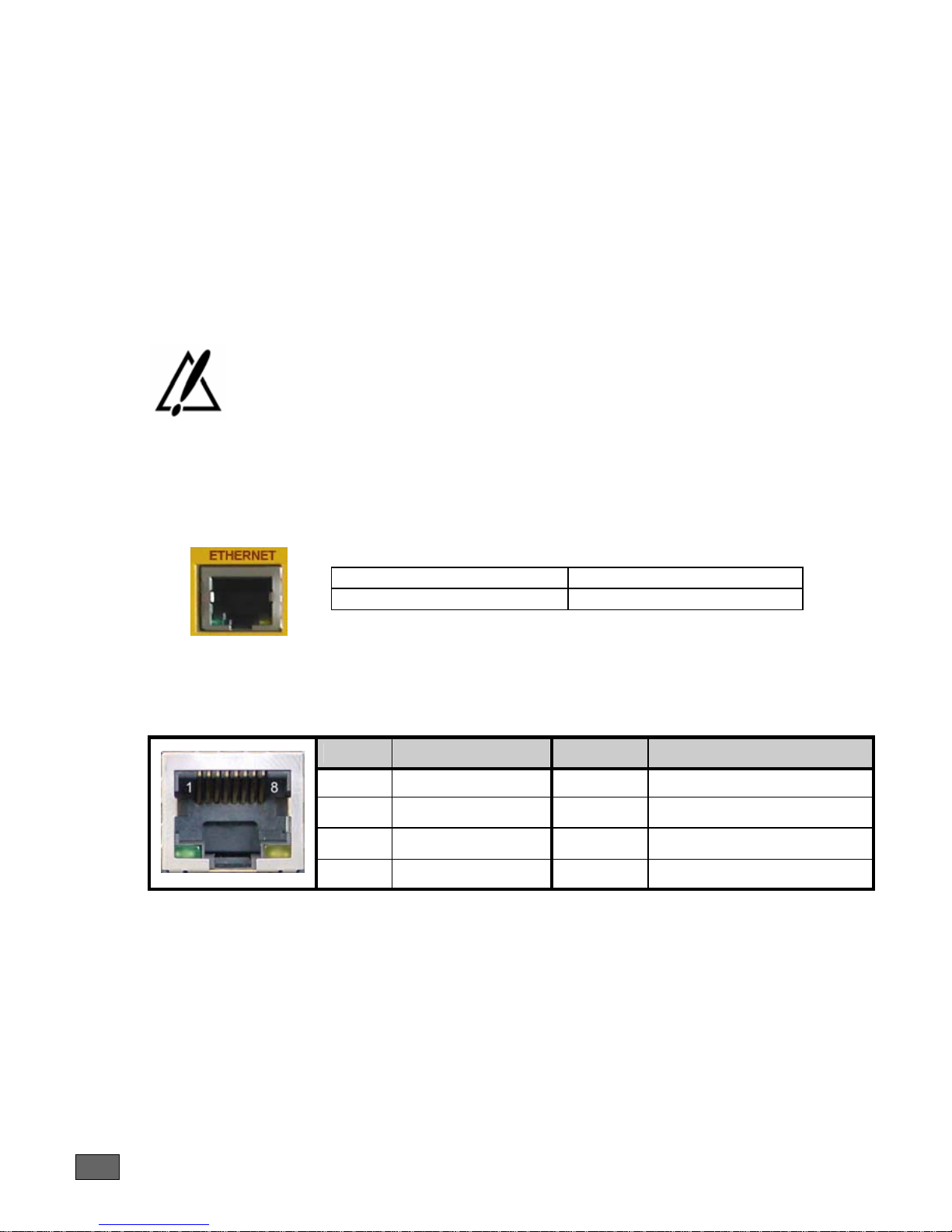
4.1 LAN 10/100 Mbps Interface (FASTETHERNET)
4.1.1 Characteristics
• 100Base-TX,
• Full duplex,
• Auto-negotiation.
• Auto MDI/MDX
The Ethernet interfaces of the ONECell25 only support the 100 Mbps fullduplex operations in auto-sense mode. If connected to devices in 10 mbps
or half-duplex, the ONECell25 interface will not be connected. The problem
can appear mostly with devices forced in such mode or with old Ethernet
hub.
4.1.2 Meaning of LED Colors
Lit green Led Link active
Blinking yellow Led Traffic in progress
4.1.3 Connector Pinout
RJ45 Connector:
Pin Signal Pin Signal
1 TD (+) 5 NC
2 TD (-) 6 RD (-)
3 RD (+) 7 NC
4 NC 8 NC
4.1.4 Cables
A standard Ethernet cable is needed (shielded UTP Cat. 5).
13
ONECELL25 - Installation Manual
Page 14
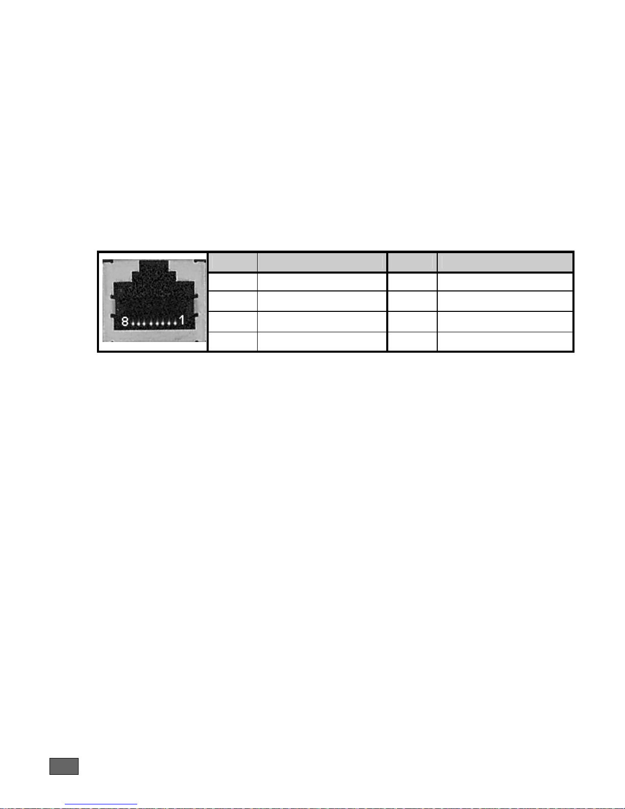
4.2 Console port (CONSOLE)
4.2.1 Characteristics
• RS 232,
• 9600 bps,
• 8 bits, 1 bit for stop, no parity.
• No flow control
4.2.2 Connector Pinout
RJ45 Connector:
Pin Signal Pin Signal
1 TX 5
2 RX 6
3 GND 7
4 NC 8
NC
NC
NC
NC
- TX: Transmission
- RX: Reception
- NC: Not connected
- GND: Ground
A console cable for router configuration a nd maintenance only requires T X, RX and
GND to be connected.
4.2.3 Cables
The console cable is defined in Appendix A.
14
ONECELL25 - Installation Manual
Page 15
5 Technical Characteristics
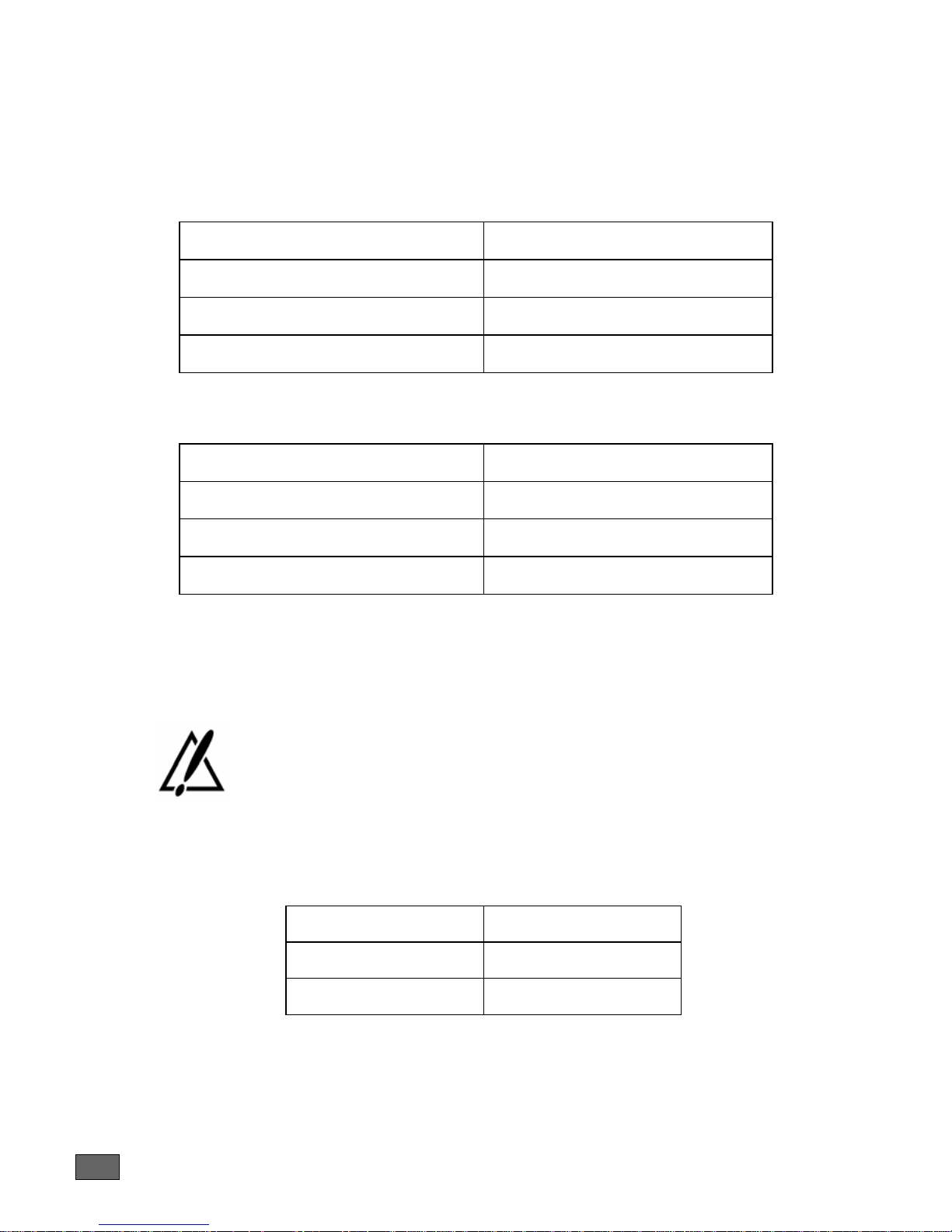
5.1 Climatic Environment
Operating Conditions:
Temperature
Relative Humidity (HR)
Absolute Humidity
Altitude
Storage Environment:
Temperature
Relative Humidity (HR)
Absolute Humidity
Altitude
5.2 Power Supply
• External Po wer Supply OneAccess 200-240 VAC / 20W (12V – 1,7A),
• External Po wer Supply OneAccess 230 VAC / 12W (12V – 1A),
0° C ≤ T ≤ 45°C
5% ≤ HR ≤ 80%
≤ 24g / m3
≤ 2500 m
- 25° C ≤ T ≤ 55°C
5% ≤ HR ≤ 80%
≤ 24g / m3
≤ 2500 m
Using another power supply than the on es recommended by OneAccess
causes the product warranty to be void.
5.3 Dimensions
The dimensions of the housing are:
15
Width 152 mm
Height 26 mm
Depth 102 mm
ONECELL25 - Installation Manual
Page 16
6 Installation
Always unplug the power AC cable before any hardware maintenance
operation.
This chapter describes assembling/disassembling operations.
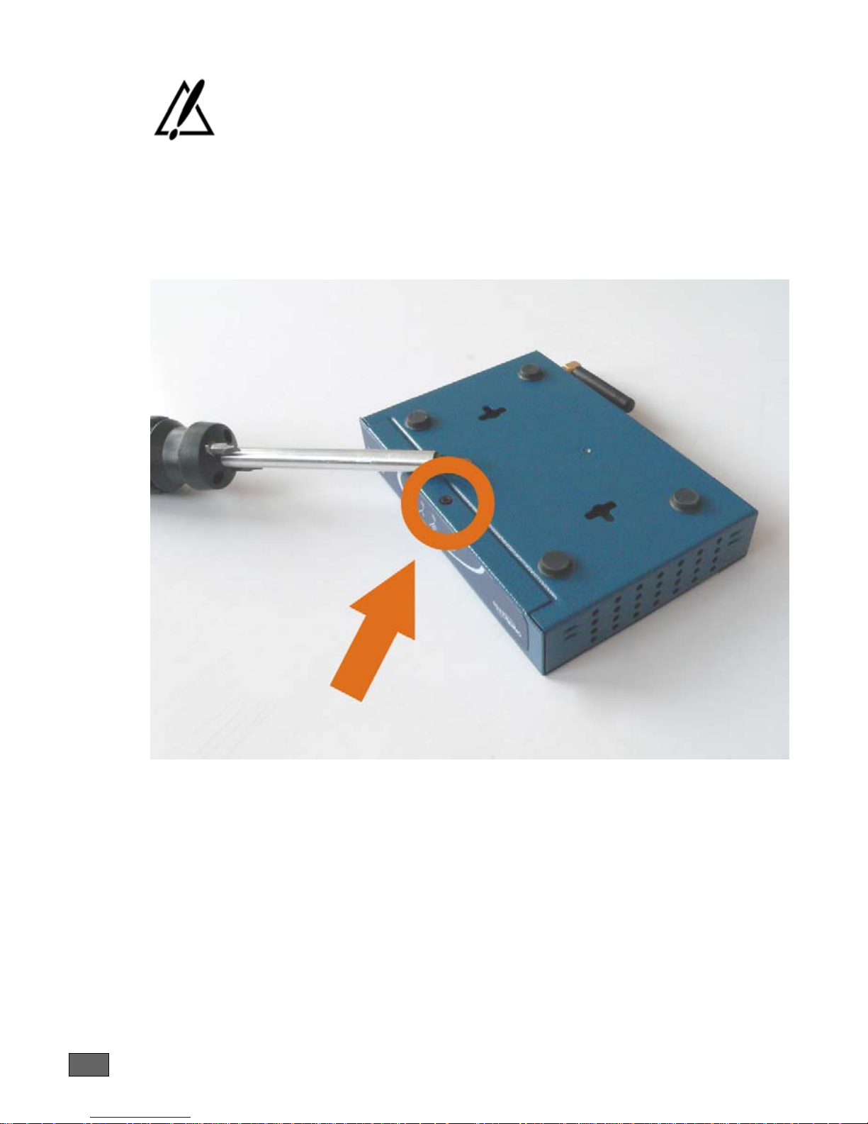
6.1 Opening Casing
1 Unlock the screw at the bottom of the product and remove it.
2 Remove the cover by sliding horizontally the cover away from the bottom part of
the casing.
16
ONECELL25 - Installation Manual
Page 17
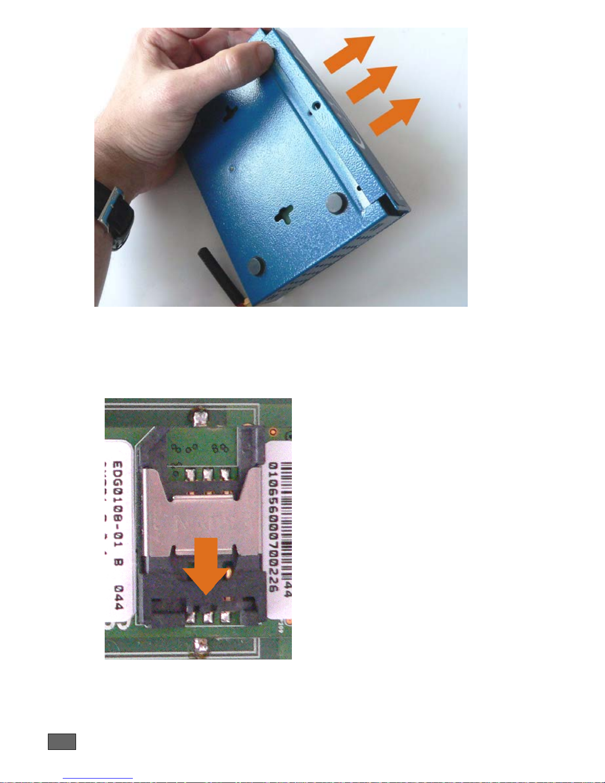
6.2 Installing SIM Card
The casing must be open. The steps are the following:
1 Unlock the SIM card holder by sliding the locking metal piece as i ndicated on the
picture below
2 Raise the SIM card holder in vertical position
17
ONECELL25 - Installation Manual
Page 18
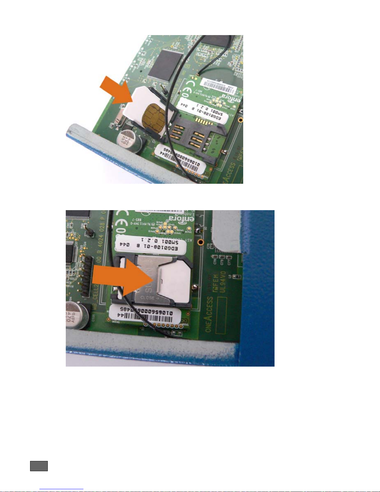
3 Insert the SIM card; make sure the SIM card is inserted in the right position as
shown on the picture below.
4 Put the SIM card holder in its former position and lock it.
18
ONECELL25 - Installation Manual
Page 19
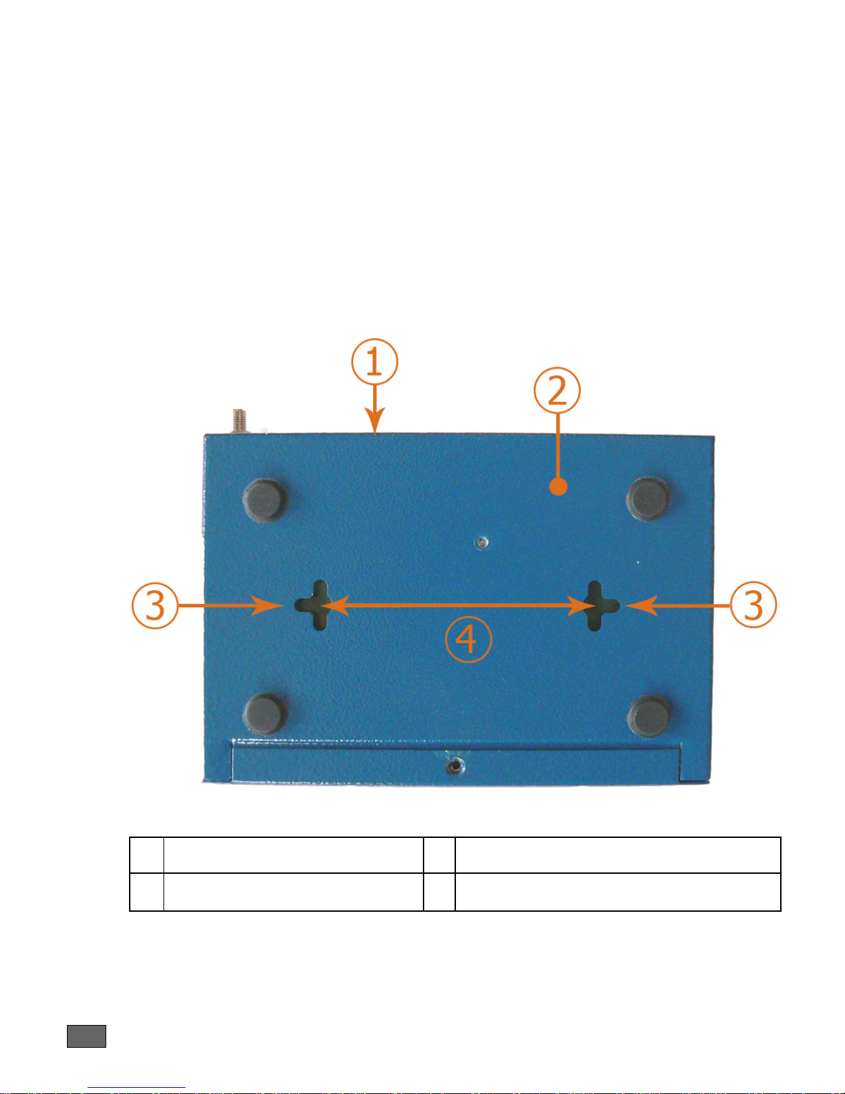
6.3 Wall Mounting
The lower part of the router has 2 notches in order to enable wall-mounting. By
installing two screws at the required distance, the router can be hung on any vertical
surface.
Instructions:
1. Bore two horizontal holes separated by 80 mm of distance if the router is
hung with the rear panel in the upper position
2. Mount both screws in each hole. Do not screw them completely but leave a
distance of 5 mm between the wall and the head of the screw,
3. Hang the router gently and if necessary adjust the screws in the notch es of
the router.
1 Rear panel of the router 3 Notches
2 Bottom of the router 4 Distance between holes: 80 mm
19
Figure 4. Positioning of the notches
ONECELL25 - Installation Manual
Page 20

6.4 Connections
The external power supply is connected on the rear panel of the device.
The external power supply is delivere d with the router package. Connect the ’jack’
connector of the external power supply to the connector marked ’12V-1A’ device
connector,
The router shall not be used with anoth er power supply than a power supply
recommended by OneAccess. Using another power supply than the ones
recommended by OneAccess causes the product warranty to be void.
20
ONECELL25 - Installation Manual
Page 21

7 Power up
To power up the device, always follow these steps:
• Connect the DC po wer input jack from the power supply to the DC power
input of the rear panel of the router,
• Connect the power supply to the AC mains (200- 240 V AC).
Few seconds after power-on, the device performs a series of self-tests and loads
the software into memory (RAM), during which the ’ST AT US’ LED o n the front p anel
blinks.
At the end of software loading (about 30 seconds):
• The ’ST ATUS’ LED light remains steady green if software initialization was
successful,
• The ’ST ATUS’ LED blinks in case of software absence or error during
software loading.
21
ONECELL25 - Installation Manual
Page 22
8 Getting Started
When the router is delivered with the default OneAccess factory settings, the router
is configured as follows:
• FASTETHERNET 0/0 port is configured with the IP address 192.168.1.1
(netmask: 255.255.255.0)
• DHCP server is enabled
• HTTP server for fast web-based configuration is enabled
8.1 Connect your PC
Your PC should be configured to acquire its IP address via DHCP protocol;
alternatively, you can assign a static IP address to your PC LAN interface in the
network range 192.168.1.2 – 192.168.1.254.
Connect your PC with a LAN cable (straight or crossed; the ONECell25 adapts to
both wiring).
The Ethernet interfaces of the ONECell25 only support the 100 Mbps fullduplex operations in auto-sense mode. If connected to devices in 10 mbps
or half-duplex, the ONECell25 interface will not be connected. The problem
can appear mostly with devices forced in such mode or with old Ethernet
hub.
8.2 Starting the Web Configurator
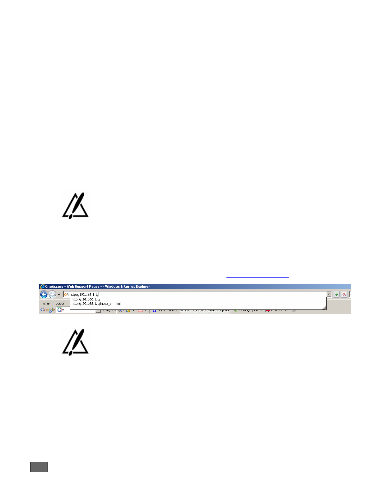
Open a web browser and use the following URL: http://192.168.1.1/
The web configurator developed by OneAccess uses intensively javascript.
It has been tested with Internet Explorer version 6 and 7 as well as Firefox 2.
Using the web configurator with other web browsers may not work and are
not supported by OneAccess.
You will be directed to a login page. The default login is webadmin and the
password is admin.
It is recommended to use the EDGE connection wizard to setup the EDGE
connection.
Please consult the web user manual for more details.
22
ONECELL25 - Installation Manual
Page 23

8.3 Restoring Factory Settings
It might happen that:
• Access passwords to the web interface are lost
• New configuration parameters (such as firewall or unknown LAN IP) are such
that you cannot connect to the ONECELL25 web configurator
In that case, the restore factory settings will help you because, the following factory
settings are restored:
• Software and web configurator loaded at manufacturing time
• Factory configuration files
• Factory default passwords
If the factory restore option is set (default OneAccess settings), one can now use
the factory restore procedure. It is triggered as follows:
• Power-on the product
• The ‘Status’ LED blinks very quickly, then it blinks more slowly.
• When all LEDs of the front panel are lit, unplug the power cable.
• Repeat the process three times and then let the router boot. The restore
operation will be done.
8.4 Configuration by Telnet / SSH / Console
The default telnet/console login / password is admin / admin. It is highly
recommended to change the default pass word from web interface to avoid intrusion
from hackers.
The ONECell25 has many powerful features that cannot be configured and
managed via the web Configurator.
Any user can use the console at own risks:
• It may cause the web Configurator not to work properly
• OneAccess only supports customers having with a maintenance contract with
OneAccess and being certified, trained users
8.5 Getting Support on ONECell25
Please use this link to get more documents and help:
http://www.oneaccess-net.com/en/cell
23
ONECELL25 - Installation Manual
Page 24
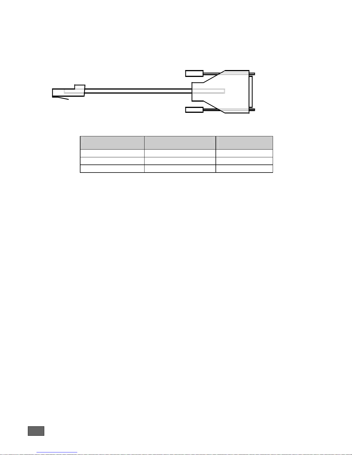
Appendix A - Console Cable
Catalog reference: 4 022 332 B 00 Ed A
P1
RJ45 - P1 SIGNAL SUB-D 9 Pts
1 TX 2
2 RX 3
3 GND 5
To PC
seri al por t
P2
i n terminal
mode
(Configuration)
Female - P2
24
ONECELL25 - Installation Manual
 Loading...