

Page 1

ONE80
Installation Manual
http://www.oneaccess-net.com
Version B
April 2007
ONE80 – Installation Manual
1
Page 2

OneAccess
28, rue de la Redoute
92260 Fontenay aux Roses
France
The law of 11 March 1957, paragraphs 2 and 3 of article 41, only authorizes, firstly,
’copies and reproductions strictly reserved for use by copyists and not for general
use and, secondly, analyses and short quotations for the purpose of example and
illustration. Therefore, ’any representation or reproduction, entire or partial, made
without the consent of the author or his representatives is illegal’ (paragraph 1 of
article 40).
Any such representation or reproduction, made in any manner whatsoever, would
therefore constitute an infringement of the law as sanctioned by articles 425 and in
accordance with the penal code.
Information contained in this document is subject to change without prior notice and
does not constitute any form of obligation on the part of OneAccess.
OneAccess and the distributors can in no case be held responsible for direct or
indirect damage of any kind incurred as a result of any error in the software or
guide.
Every care has been taken to ensure the exactitude of information in this manual. If
however you discover an error, please contact OneAccess After Sales Service
division.
Edition August 2006
1000 00 N 4022 844 C 00 ind. B
2
ONE80 – Installation Manual
Page 3

How to Read this Manual
The present document is broken down into 8 chapters.
Chapter 1 – Safety Instructions
This chapter provides the safety instructions for use and installation of the router.
Chapter 2 – Router Description
This section describes the router front and rear panels and the assoc iated technical
characteristics.
Chapter 3 – Interface Description
This section describes the router interfaces.
Chapter 4 - Installation
This chapter describes how to modify the jumper positions and gives instructions to
connect the router.
Chapter 5 – Power-up
This chapter describes the device power-up and how to monitor the self-test
progress.
Chapter 6 – Technical Characteristics
This section describes technical characteristics such as operating conditions.
Chapter 7 – Directives and Standards
This chapter details the list of standards, which the device complies with.
Appendix – Connection Description
This chapter provides the pin-out of cables that are compatible with the router.
ONE80 – Installation Manual
3
Page 4

Table of Contents
HOW TO READ THIS MANUAL ...........................................................................................................................3
TABLE OF CONTENTS...........................................................................................................................................4
1 SAFETY INSTRUCTIONS...........................................................................................................................5
1.1 Connection to Power Supply .....................................................................................................................5
1.2 Overcurrent Protection...............................................................................................................................5
1.3 Safety Level Interface ................................................................................................................................5
2 DIRECTIVES AND STANDARDS .............................................................................................................6
2.1 Declaration of Conformity.........................................................................................................................6
2.2 Standards....................................................................................................................................................7
3 ROUTER DESCRIPTION.............................................................................................................................8
3.1 Hardware Description ................................................................................................................................8
3.2 Front Panel .................................................................................................................................................9
3.3 Rear Panel ................................................................................................................................................10
3.4 Configuration Identification.....................................................................................................................12
4 INTERFACE DESCRIPTION.....................................................................................................................13
4.1 G.SHDSL Interface (SHDSL) .................................................................................................................13
4.2 Console interface (CONSOLE) ...............................................................................................................14
4.3 LAN 10/100 Mbps interface (ETHERNET)............................................................................................15
4.4 Switch Interface (SWITCH) ....................................................................................................................16
5 INSTALLATION.........................................................................................................................................17
5.1 Connection ...............................................................................................................................................17
6 POWER-UP .................................................................................................................................................18
7 TECHNICAL CHARACTERISTICS .........................................................................................................19
7.1 Climatic Environment..............................................................................................................................19
7.2 Power Supply ...........................................................................................................................................19
7.3 Dimensions...............................................................................................................................................19
8 DIRECTIVES AND STANDARDS ...........................................................................................................20
8.1 Declaration of Conformity.......................................................................................................................20
8.2 Standards..................................................................................................................................................21
ANNEXE A: CONSOLE CABLE..........................................................................................................................23
4
ONE80 – Installation Manual
Page 5

1 Safety Instructions
The following symbol instructs the user to read the manual carefully before any
connection:
1.1 Connection to Power Supply
To connect the power supply, always follow these steps:
• Connect the D C input jack from the power supply to the DC 12V power input
on the rear panel of the router,
• Connect the po wer sup pl y to an AC electrical outlet (100-240 VAC). Plugging
in the power supply turns on the router.
Unplug the AC input before assembling/disassembling any part on the
device. The AC input is the part you must disconnect first. For safety reasons, you shall be able to easily access this part.
1.2 Overcurrent Protection
The product requires that the building’s electrical installation is designed for
protection against short-circuit (over current) protection.
A fuse or circuit breaker no larger than 240 VAC, 1 0A must be used on the phase
conductors.
1.3 Safety Level Interface
All safety levels of the interfaces are described in each paragraph presenting the
interfaces (paragraphs 3.1 to 3.4).
The interface modules and optional boards can be installed only in the
products authorized by OneAccess and only by qualified staff as
recommended in the installation manual.
ONE80 – Installation Manual
5
Page 6

2 Directives and Standards
2.1 Declaration of Conformity
6
ONE80 – Installation Manual
Page 7
2.2 Standards
The ONE80 is designed in c onformity with the standards listed hereafter, provided
that the basic housing, modules, interface boards and installation kits are mounted
as recommended in the corresponding installation manual(s ).
Safety
EN60950-1: 2001, First
Edition
Safety of information technology equipment, including electrical
business equipment.
Environment:
Climatic, physico chemical, mechanic, packing
ETS 300 019-1 (95) Environmental conditions and environmental testing for
telecommunication equipment
In use: Temperature Controlled
Test specification:
Part 1, Classification of environmental conditions
- class T3.1 (normal)
- class T3.1 (exceptional)
Storage: partly temperature controlled
T1.1 Part 2, Specification of environmental test
Transportation: careful Transportation
T2.3
Electromagnetic Compatibility, immunity
ETSI EN 301 489-17 V1.2.1
(2002-08)
ElectroMagnetic Compatibility (EMC) standard for radio equipment
and services.
Part 17: Specific conditions for 2,4 GHz wideband transmission
systems and 5 GHz high performance RLAN equipment.
ETSI EN 300 328 V1.6.1
Data transmission equipment operating in the 2,4 GHz ISM band
and using wide band modulation techniques;
Harmonized EN covering essential requirements under article 3.2
of the R&TTE Directive.
ETSI EN 300 386 V.1.3.3
(2005-04)
Telecommunication network equipment;
ElectroMagnetic Compatibility (EMC) requirements.
Waste Electrical and Electronic Equipment
202/96/EC
Restricted use of Hazardous Substances (RoHS)
2002/95/EC
The ONE80 respects the European directive on the waste disposal
from the electrical and electronics components.
The ONE80 respects the European directive on the restricted use
of Hazardous Substances in electric and electronic equipment.
ONE80 – Installation Manual
7
Page 8

3 Router Description
3.1 Hardware Description
This section details the various types of services offered by the ONE80. The
described configurations are the maximum configurations for the motherboard and
the extension modules. Other configurations can be derived by under-equipment.
Indeed, the ONE80 can have fewer interfaces compared to those presented below.
The acronyms mentioned in bold between brackets locate markings of the interfaces
back panel.
3.1.1 Motherboard Interface
The ONE80 motherboard is equipped with the following interfaces. The interface
marking is indicated in bold and between brackets.
• 1 G.SHDSL access network (2 or 4 wires) or IMA SHDSL (8 wires) (SHDSL),
• 1 Cons ole port (CONSOLE),
• 1 Managed switch 4 ports (SWITCH).
• 1 LAN access 10/100 Mbps (ETHERNET),
Optional Interfaces factory mounted:
• WLAN 802.11b/g with 2 antennas (managed by the method « antenna
diversity »).
8
ONE80 – Installation Manual
Page 9
3.2 Front Panel
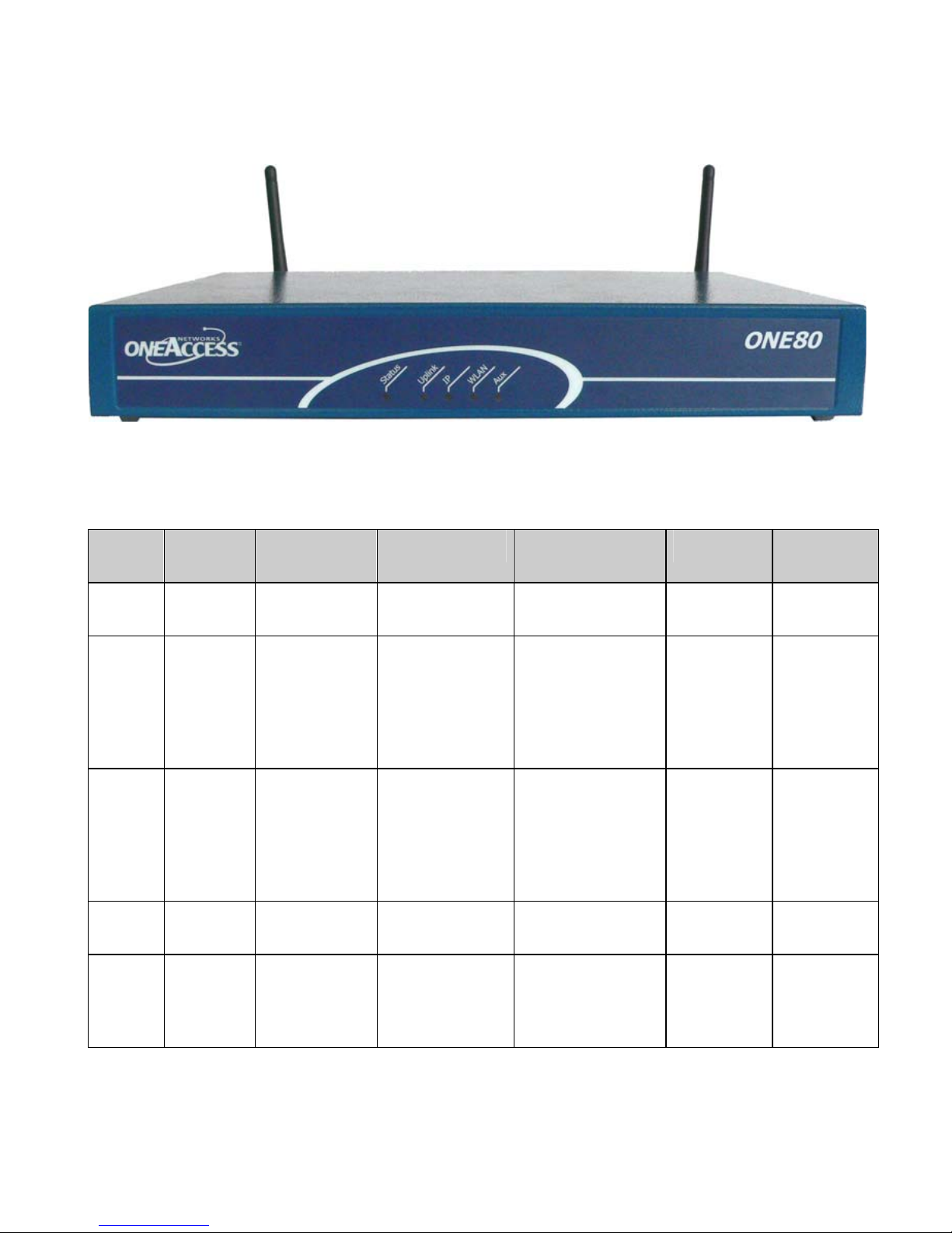
The front panel is provided with LEDS, which inform about the status of several
router functions.
Figure 1. Front Panel
Leds OFF Green Red Blinking Red Orange Blinking
Green
Status Switched
Off
Uplink No
SHDSL
lines
configured
IP Not used All IP
WLAN Not used Interface up Traffic in
Aux No auto
configurat
ion
Switched On
& Operational
All SHDSL
lines are
synchronized
interfaces are
up
Auto
configuration
successfully
completed
Switched On &
Not operational
All SHDSL lines
are not
synchronized
(loss of signal)
All IP interfaces
are down
Auto
Reboot in
progress
Minimum one
configured
SHDSL line is not
synchronized
(loss of signal)
At least one
Minimum
one SHDSL
line is in the
progress of
synchroniz
ation
IP Interface
is not up
(example:
PPPoA not
connected)
progress
configuratio
n in
progress
ONE80 – Installation Manual
9
Page 10

3.3 Rear Panel
This section details the various types of ONE80 rear panel so that the user can
identify the interface type and port numbering.
It should be noted that only the full y-loaded configurations are represented.
Other configurations can be derived by not providing some interfaces
represented on the product. The configuratio ns below are presented as an
example. OneAccess reserves the right to market them or not.
10
ONE80 – Installation Manual
Page 11
3.3.1 Configuration
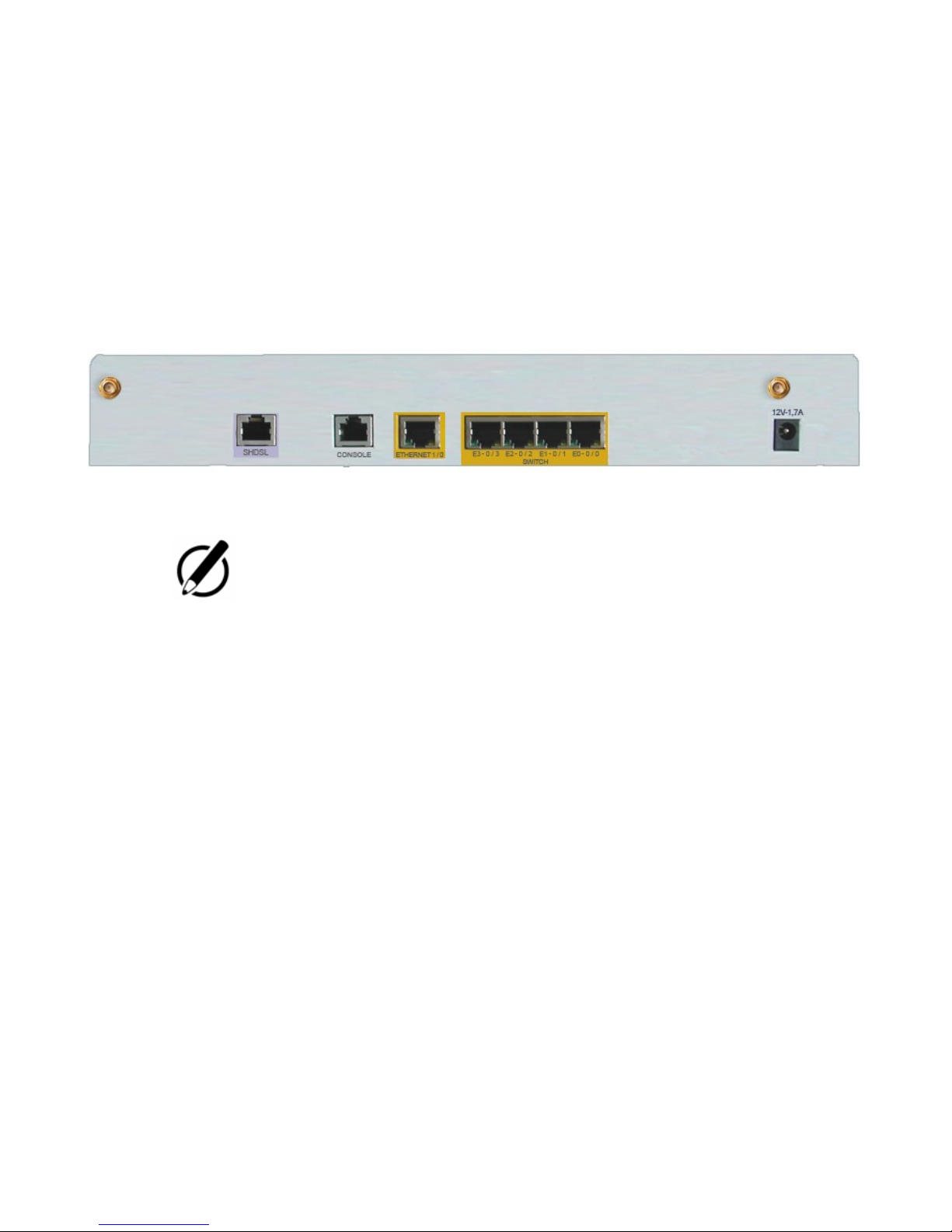
The interface marking is indicated in bold and bet ween br ackets.
All the connectors are located on the rear panel:
• 1 SHDSL acc ess port (RJ45) (SHDSL),
• 1 Configuration port and debug (RJ45) (CONSOLE),
• 1 LAN access port 100Base-T (RJ45) (ETHERNET 1/0),
• 4 FastEthernet switch ports (RJ45) (SWITCH E3-0/3 to E0-0/0),
• Input for the external p ower supply connector (DC input jack, 12V-1.7A),
• 2 connectors for W LAN antenna.
Figure 2. Rear panel
Depending of t he ordered configuration of the system, the rear panel may
change.
ONE80 – Installation Manual
11
Page 12

3.4 Configuration Identification
The different device configurations are identif ied by adding one or several letters to
the device naming and printed on the router labelling sticker.
Option codification:
• D: G.SHDSL access 1 to 2 pairs (2 to 4 wires),
• M: IMA access G.SHDSL 4 pairs (8 wires),
• W: Wireless LAN
Example:
ONE80 M is an ONE80 router equipped with:
• 1 IMA access G.SHDSL 8 wires.
12
ONE80 – Installation Manual
Page 13
4 Interface Description
4.1 G.SHDSL Interface (SHDSL)
4.1.1 Safety Level of G.SHDSL (SHDSL) Interface
The G.SHDSL interface is TNV-1 (Telephone Network Voltage type 1).
It must be connected to a standard telephone line (external).
4.1.2 Characteristics
• ITU-T G.991.2 for the G.SHDSL (Annex A and B), 2 or 4 wires,
• Capacity:
• SHDSL 1 pair (2 wires): 192 kbps up to 2 320 kbps,
• SHDSL 2 pairs (4 wires): 384 kbps up to 4 640 kbps,
• SHDSL IMA G.SHDSL 4 pairs (8 wires): 768 kbps up to 9 280 kbps.
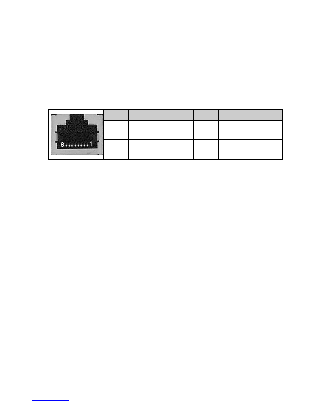
4.1.3 Connector Pinout
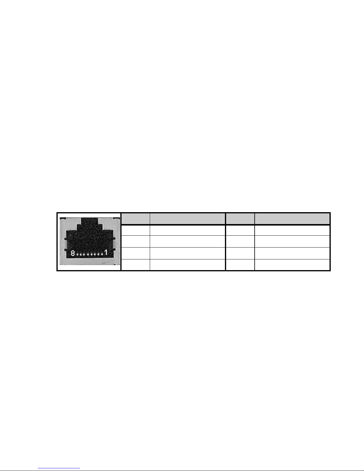
RJ45 connector:
4.1.4 Cables
For the connection of the G.SHDSHL interface, us e the shielded cable that comes
with the equipment.
Pin Signal Pin Signal
1 Line 2 5 Line 1
2 Line 2 6 Line 3
3 Line 3 7 Line 4
4 Line 1 8 Line 4
ONE80 – Installation Manual
13
Page 14
4.2 Console interface (CONSOLE)
4.2.1 Characteristics
• RS232,
• 9600 bps,
• 8 bits, 1 bit for stop, no parity.
4.2.2 Connector Pinout
RJ45 connector:
Pin Signal Pin Signal
• TX: Emission
• RX: Reception
• NC: Not Connec ted
• GND: Ground
4.2.3 Cable
The console cable is defined in Appendix A.
1 TX 5
2 RX 6
3 GND 7
4 NC 8
NC
NC
NC
NC
14
ONE80 – Installation Manual
Page 15
4.3 LAN 10/100 Mbps interface (ETHERNET)
4.3.1 Safety level of LAN 10/100 Mbps interface
The Ethernet 10/100 Mbps auto-sense has a ’SELV’ (Safety Extra Low Voltage)
interface.
They must be used only for indoor applications, connected to a 10/100 Mbps
interface, which has also the ’SELV’ characteristics.
4.3.2 Characteristics
• 10Bas e-T and 100Base-TX,
• Half or full duplex,
• Auto negotiation.
• Auto MDI/MDIX.
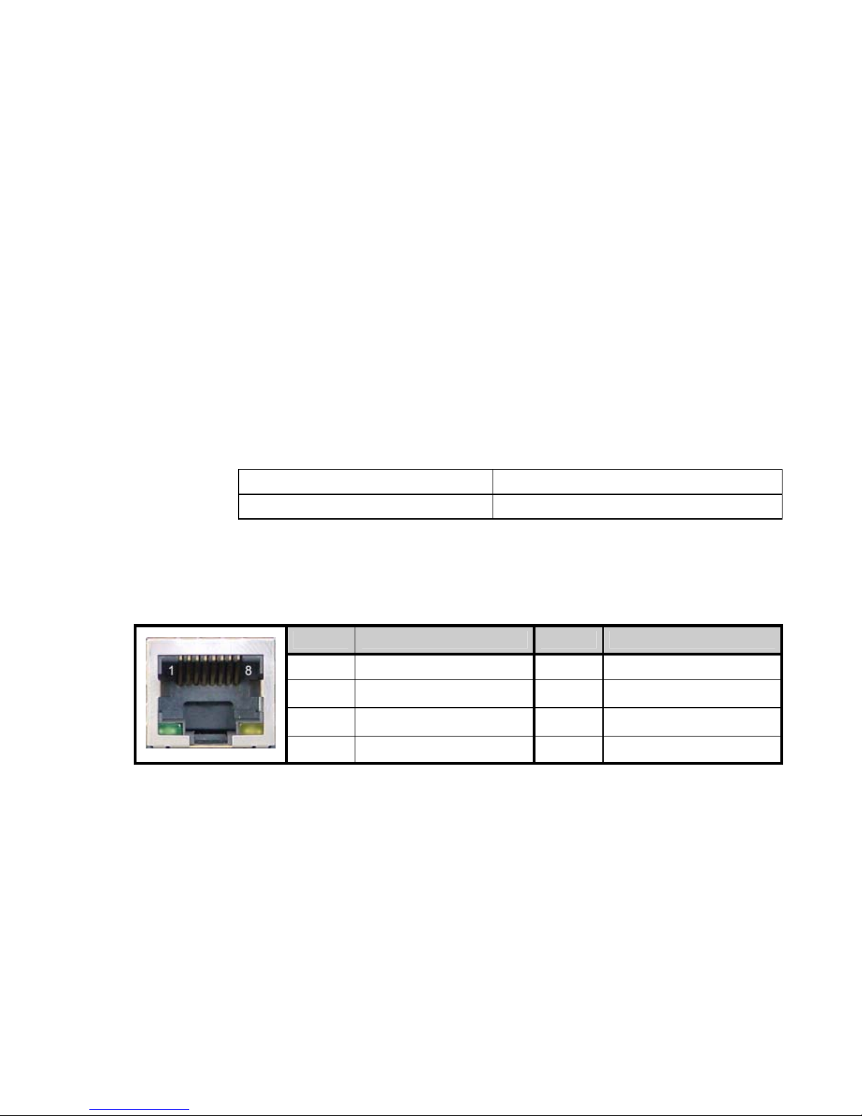
4.3.3 Meaning of LED Colors
4.3.4 Pinout
RJ45 Connector:
4.3.5 Cables
The cables are shielded, crossover/straight cables with 4 twisted pairs. The s witch
supports auto detection of crossover/straight cable (’auto-MDI/MDI-X detection’); the
transmission pairs are (1-2) and receive (3-6).
Green LED Lit Link active
Blinking yellow LED Traffic in progress
Pin Signal Pin Signal
1 TD (+) 5 NC
2 TD (-) 6 RD (-)
3 RD (+) 7 NC
4 NC 8 NC
ONE80 – Installation Manual
15
Page 16
4.4 Switch Interface (SWITCH)
4.4.1 Safety level of Switch interface
The Ethernet 10/100 Mbps auto-sense has a ’SELV’ (Safety Extra Low Voltage)
interface.
They must be used only for indoor applications, connected to a 10/100 Mbps
interface, which has also the ’SELV’ characteristics.
4.4.2 Characteristics
The Ethernet Switch function offers 4 additio nal Ethernet po rts. Each of thi s port can
be switched and/or routed.
• 10/100 Mbits/s,
• Half or full duplex,
• Auto-negotiation,
• Auto MDI/MDIX.
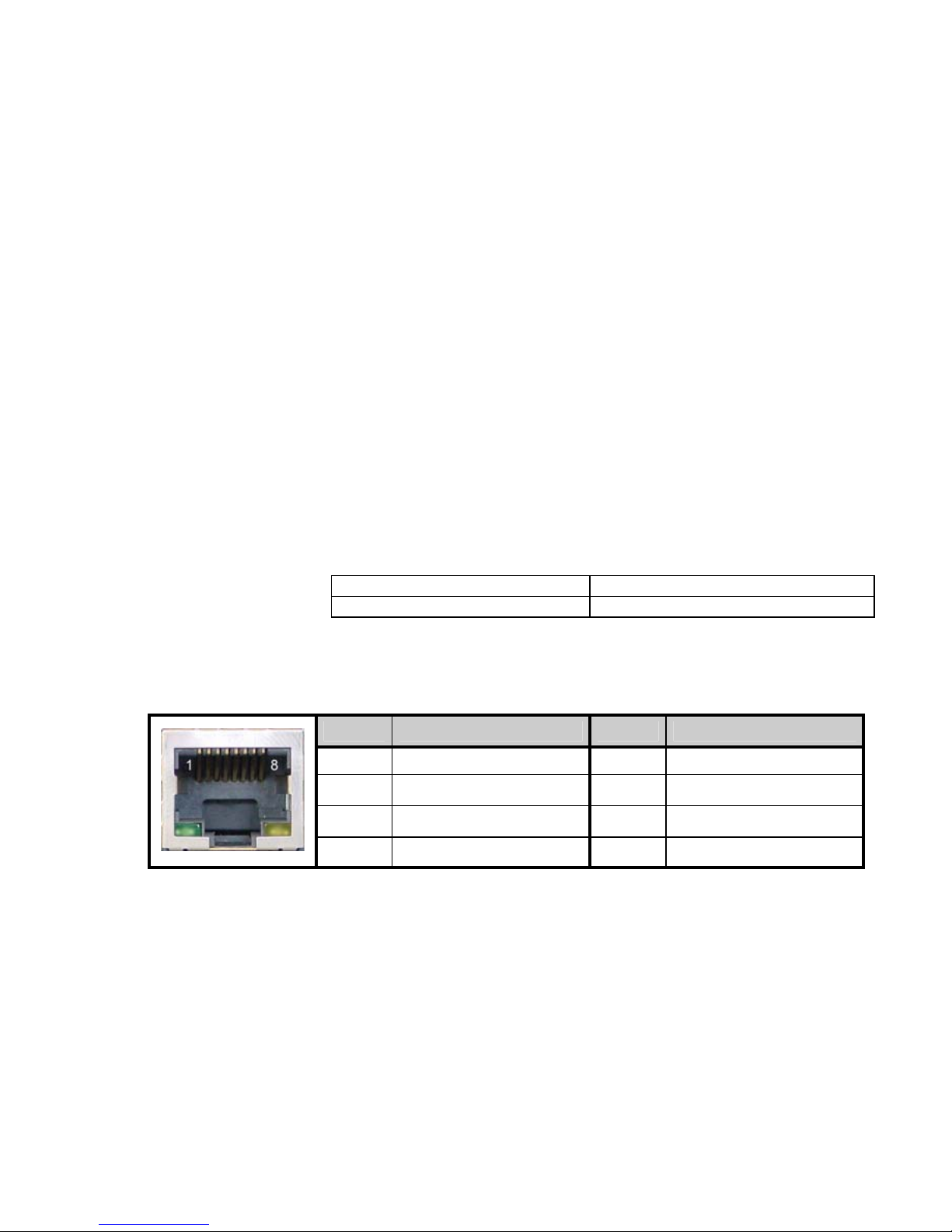
4.4.3 Meaning of LED colors
4.4.4 Connector Pinout
RJ45 connector:
4.4.5 Cables
The cables are shielded, crossover/straight cables with 4 twisted pairs. The s witch
supports auto detection of crossover/straight cable (’auto-MDI/MDI-X detection’); the
transmission pairs are (1-2) and receive (3-6).
Green LED Lit Link active
Blinking yellow LED Traffic in progress
Pin Signal Pin Signal
1 TD (+) 5 NC
2 TD (-) 6 RD (-)
3 RD (+) 7 NC
4 NC 8 NC
16
ONE80 – Installation Manual
Page 17

5 Installation
Always unplug the power AC cable before any hardware maintenance
operation.
This chapter describes how to connect the router.
5.1 Connection
The external power supply is connected on the rear panel of the device.
The external power supply is delivered with the router package.
• Connect the ’jack’ connector of the external power supply to the DC “12V –
1,7A” power input device connector,
• Connect the D C input jack from the power supply to the DC “12V-1,7A” power
input on the rear panel of the router,
• Secure the power supply connection by installing the DC power supply co rd
into the plastic ring.
The device shall not be used with another power supply than a power
supply provided by OneAccess.
ONE80 – Installation Manual
17
Page 18

6 Power-up
To power up the device, always follow these steps:
• Connect the DC power input jack from the power supply to the DC power
input of the rear panel of the router,
• Connect the power supply to the AC mains (100-240 V AC).
The connection of the power supply causes the switch-on of the equipment.
Few seconds after power-on, the device performs a series of self-tests and loads
the software into memory (RAM), during which the ’STATUS’ LED on the front
panel blinks:
• The ’STATUS’ LED light remains steady green if software initialization was
successful,
• The ’STATUS’ LED blinks in case of software absence or error during
software loading.
Refer to the Software and ONEOS User Guide for more information.
18
ONE80 – Installation Manual
Page 19

7 Technical Characteristics
7.1 Climatic Environment
Operating Conditions:
Temperature
Relative Humidity (HR)
Absolute Humidity
Altitude
Storage Environment:
Temperature - 25° C to 55° C
Relative Humidity (HR)
Absolute Humidity
Altitude
7.2 Power Supply
External Power Supply 100-240 VAC / 20W (12V – 1,7A).
0° C ≤ T ≤ 45°C
5% ≤ HR ≤ 80%
≤ 24g / m3
≤ 2500 m
5% ≤ HR ≤ 80%
≤ 24g / m3
≤ 2500 m
7.3 Dimensions
The dimensions of the housing are:
Width
Height
Depth
320 mm
1 U
200 mm
ONE80 – Installation Manual
19
Page 20

8 Directives and Standards
8.1 Declaration of Conformity
In progress
20
ONE80 – Installation Manual
Page 21

8.2 Standards
The ONE80 is designed in c onformity with the standards listed hereafter, provided
that the basic housing, modules, interface boards and installation kits are mounted
as recommended in the corresponding installation manual(s ).
Security
EN60950-1:2001
First Edition
Safety of information technology equipment, including electrical
business equipment.
Energy
ETSI EN 300 132
Power supply interface at the input to telecommunications
equipment
Operated by alternating current (ac) derived from direct current (dc)
• Part 1
• Part 3
sources ETSI EN 300 132-3 : Power supply interface at the input t o
telecommunications equipment
Operated by rectified current source, alternating current source or
direct current source up to 400 V Security
Environment :
Climatic, physico chemical, mechanic, packing
ETS 300 019-1 (95) Environmental conditions and environmental testing for
telecommunication equipment
In use : Temperature Controlled
Test specification:
Part 1, Classification of environmental conditions
- class T3.1 (normal)
- class T3.1
(exceptionnal)
Storage: partly temperature controlled
T1.1 Part 2, Specification of environmental test
Transportation: careful transportation
T2.3
ONE80 – Installation Manual
21
Page 22

Telecom
ITU-T K21 on G.SHDSL
(2003-07)
Electromagnetic Compatibility, immunity
EN 300386 V.1.3.3
(2005-04)
EN 301489-17 V1.2.1
(2002-08)
EN 300328 V1.6.1
(2004-11)
Resistibility of telecommunication equipment installed in customer
premises to over-voltages and over-currents
Telecommunication network equipment;
ElectroMagnetic Compatibility (EMC) requirements
ElectroMagnetic Compatibility (EMC) standard for radio equipment
and services;Part 17:
Specific conditions for 2,4 GHz wideband transmission systems
and 5 GHz high performance RLAN equipment
Wideband transmission systems;
Data transmission equipment operating in the 2,4 GHz ISM band
and using wide band modulation techniques;Harmonized EN
covering essential requirements under article 3.2 of the R&TTE
Directive
Waste Electrical and Electronic Equipment
2002/96/EC
The ONE80 respects the European directive on the waste disposal
from the electric and electronic equipment.
Restricted use of Hazardous Substances (RoHS)
2002/95/EC
The ONE80 respects the European directive on the restricted use
of Hazardous Substances in electric and electronic equipment.
22
ONE80 – Installation Manual
Page 23
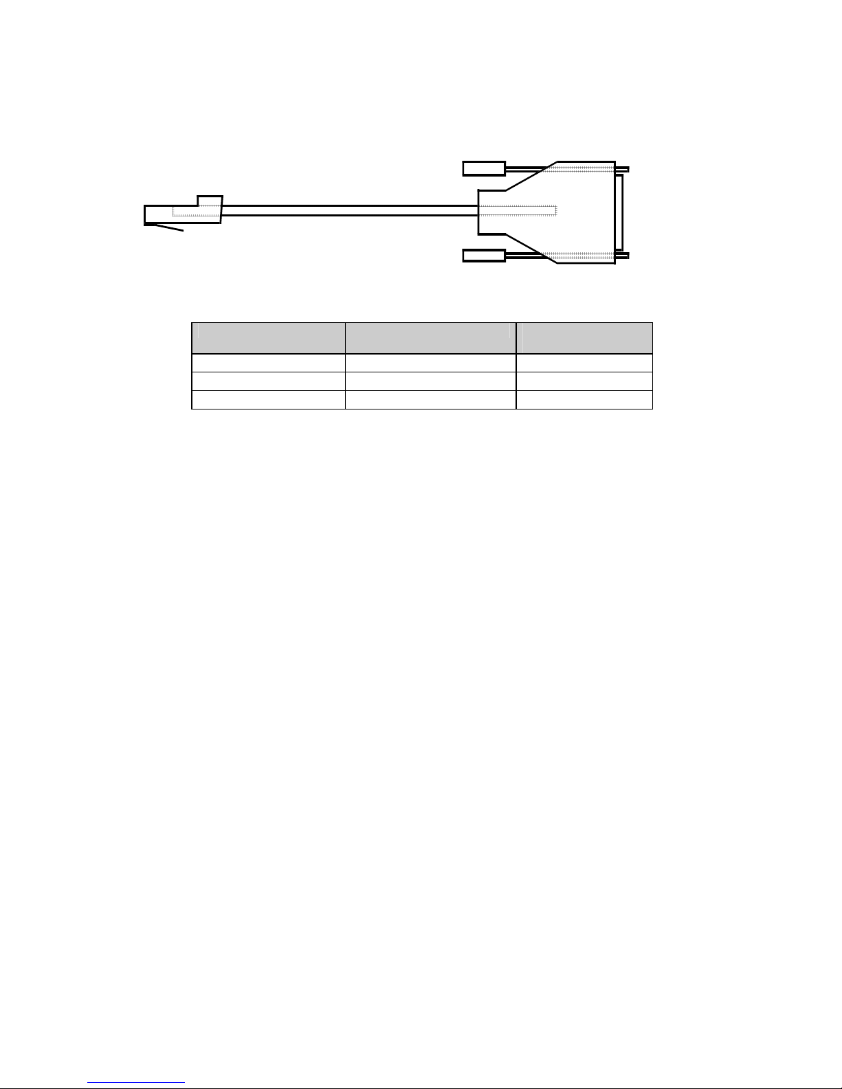
Annexe A: Console Cable
Catalog reference: 4 022 332 B 00 Ed A
P1
RJ45 - P1 SIGNAL SUB-D 9 Pts
1 TX 2
2 RX 3
3 GND 5
To PC
serial port
P2
in terminal
mode
(Configuration)
Female - P2
ONE80 – Installation Manual
23
 Loading...