

Page 1

Crocus CNV
Crocus CNV
USER and REFERENCE MANUAL
Version: 1.5 500866
Page 2

Copyright, safety and statements Crocus CNV
ii
Document properties
Subject Crocus CNV
Manual type USER and REFERENCE MANUAL
Version 1.5
Code 500866
Modification date 23 October 2007 ©OneAccess
Copyright notice
The information and descriptions contained in this publication are the property of OneAccess. Such
information and descriptions must not be copied or reproduced by any means, or disseminated or
distributed without the express prior written permission of OneAccess.
This publication could include technical inaccuracies or typographical errors, for which OneAccess never
can or shall be held liable. Changes are made periodically to the information herein; these changes will
be incorporated in new editions of this publication. OneAccess may make improvements and/or changes
in the product(s) described in this publication at any time, without prior notice.
Safety requirements
Carefully read the safety instructions at the beginning of Chapter 2 - Installing and connecting the Crocus
CNV, page 8.
Page 3

Crocus CNV Copyright, safety and statements
iii
Statements
http://www.oneaccess-net.com/telindus Æ Products Æ Choose a product Æ Downloads Æ Certificates
Hereby, ONEACCESS declares that this Crocus CNV is in compliance with the essential requirements
and other relevant provisions of Directive 1999/5/EC.
Bij deze verklaart ONEACCESS dat deze Crocus CNV in overeenstemming is met de essentiële
vereisten en andere relevante bepalingen van Richtlijn 1999/5/EC.
Par la présente, ONEACCESS déclare que ce Crocus CNV est en conformité avec les exigences
essentielles et autres articles applicables de la Directive 1999/5/EC.
Hiermit, ONEACCESS erklärt daß dieser Crocus CNV ist in Fügsamkeit mit den wesentlichen
Anforderungen und anderen relevanten Bereitstellungen von Direktive 1999/5/EC.
Mediante la presente, ONEACCESS declara que el Crocus CNV cumple con los requisitos esenciales y
las demás prescripciones relevantes de la Directiva 1999/5/CE.
A ONEACCESS declara que o Crocus CNV cumpre os principais requisitos e outras disposições da
Directiva 1999/5/EC.
Col presente, ONEACCESS dichiara che questo Crocus CNV è in acquiescenza coi requisiti essenziali e
stipulazioni attinenti ed altre di Direttivo 1999/5/EC.
Με το παρόν, η ONEACCESS δηλώνει ότι αυτό το Crocus CNV είναι συµµορφούµενο µε τις βασικές
απαιτήσεις και µε τις υπόλοιπες σχετικές διατάξεις της οδηγίας 1999/5/EC.
Page 4

Copyright, safety and statements Crocus CNV
iv
Environmental information
The crossed-out wheeled bin means that within the European Union the product must be
taken to separate collection at the product end of life. This applies to the device but also
to any accessories marked with this symbol.
Do not dispose of these products as unsorted municipal waste.
If you need more information on the collection, reuse and recycling systems, please contact your local
waste administration. You can also contact us for more information on the environmental specifications of
our products.
De doorgestreepte container wil zeggen dat binnen de Europese gemeenschap het product voor
gescheiden afvalverzameling moet worden aangeboden aan het einde van de levensduur van het
product. Dit geldt voor het toestel, maar ook voor alle toebehoren dia van dit symbool voorzien zijn. Bied
deze producten niet aan bij het gewone huisvuil.
Indien u meer informatie wenst over de systemen voor inzameling, hergebruik en recyclage, gelieve dan
uw lokale afvaldiensten te contacteren. U kan ook ons contacteren wanneer u informatie wenst over de
milieu aspecten van onze producten.
Le symbole de la poubelle sur roues barrée d’une croix signifie que ce produit doit faire l’objet d’une
collecte sélective en fin de vie au sein de l’Union Européenne. Cette mesure s’applique non seulement à
vorte appareil mais également à tout autre accessoire marqué de ce symbole. Ne jetez pas ces produits
dans les ordures ménagères non sujettes au tri sélectif.
Si vous souhaitez plus d'information concernant les systèmes de collecte, de réutilisation et de recyclage,
veuillez contactez votre service de gestion de déchets local. Vous pouvez également nous contacter pour
obtenir plus d’information au sujet des spécifications environnementales de nos produits.
Das Symbol der durchgestrichenen Abfalltonne auf Rädern bedeutet dass das Produkt in der
Europäischen Union einer getrennten Mülsammlung zugeführt werden muss. Dies gilt sowohl für das
Produkt selbst, als auch für alle mit diesem Symbol gekennzeichneten Zubehörteile. Diese Produkte
dürfen nicht über den unsortierten Hausmüll entsorgt werden.
Wenn Sie mehr Informationen brauchen über die Sammlung und Recycling Systemen, bitte konsultieren
Sie Ihre örtliche Abfälle Verwaltung. Für mehr Informationen über die Umweltaspekten unserer Produkte,
wenden Sie sich an unserer Kundendienst.
Page 5

Crocus CNV Preface
v
Organisation of this manual
This manual contains three main parts.
Part This part …
User manual shows you how to install and connect the Crocus CNV.
Reference manual gives more detailed information on the Crocus CNV. It contains a complete
description for lookup purposes.
Annexes gives additional information.
The following table gives an overview of the chapters in the user manual.
Chapter This chapter …
1 introduces the Crocus CNV.
2 explains how to install and connect the Crocus CNV. It also describes the front panel
LED indicators.
3 locates the DIP switches and straps of the Crocus CNV on the motherboard. It also
explains their function.
4 introduces the Total Maintenance Application. It shows how to connect TMA with the
Crocus CNV. It is also in this chapter that the attributes of the Crocus CNV are
introduced.
5 teaches you the basics to configure the Crocus CNV, in a step-by-step manner.
The following table gives an overview of the chapters in the reference manual.
Chapter This chapter …
6, 7, 8, 9 describes the configuration, status, performance and alarm attributes, respectively.
10 displays and labels the different elements of the Total Maintenance Application
subsystem picture.
11 gives a firmware download procedure.
11.5 uncovers the available diagnostic tests.
12 summarises the technical specifications of the Crocus CNV.
The following table gives an overview of the annexes.
Annex This annex …
Annex A shows ordering information.
Page 6
Preface Crocus CNV
vi
Conventions used in this manual
Typographical conventions
The following typographical conventions are used in this manual.
The format … is used to indicate …
Normal normal text.
Italic
• new or emphasised words
• file names and directory paths, e.g. C:\Program Files\TMA\bin\Tma.exe
Computer
computer output and code examples, e.g. NOK,1,1,Invalid command.
Computer Bold
text you have to enter at the prompt, e.g. Get sysName.
Narrow
objects and attributes in the containment tree of a device when they are
mentioned in the normal text. I.e. when they are not a part of computer input or
output.
Blue references to other parts in the manual, e.g. refer to Chapter xx - Technical
specifications.
Blue underlined a hyperlink to a web site, e.g. http://www.oneaccess-net.com/
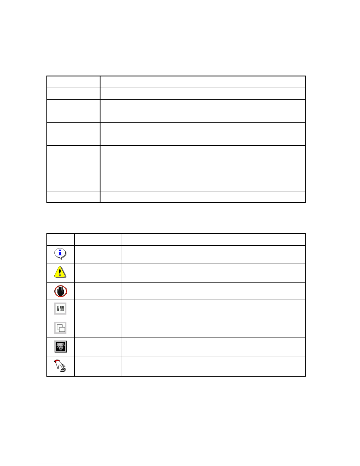
Icons
The following icons are used throughout the manual.
Icon Name Description
Remark Useful information or tips.
Caution Read the text that follows carefully in order to avoid damage to the
device.
Warning Read the text that follows carefully in order to avoid injury.
DIP switch A configuration attribute of the Crocus CNV which can be set with the
DIP switches.
Basic TMA
parameter
A basic attribute of the Crocus CNV which can be set with the Total
Maintenance Application (TMA).
Advanced TMA
parameter
An advanced attribute of the Crocus CNV which can be set with the
Total Maintenance Application (TMA).
Action An action which can be executed on the Crocus CNV with the Total
Maintenance Application (TMA).
Page 7

Crocus CNV Preface
vii
Firmware version
This manual describes the features, containment tree and attributes of the Crocus CNV firmware version
T2771/01600 (CV) and T2772/00100 (TT).
Your feedback
Your satisfaction about this purchase is an extremely important priority to all of us at OneAccess.
Accordingly, all electronic, functional and cosmetic aspects of this new unit have been carefully and
thoroughly tested and inspected. If any fault is found with this unit or should you have any other qualityrelated comment concerning this delivery, please submit the Quality Comment Form on our web page at
http://www.oneaccess-net.com/telindus
Î Support.
Page 8

Table of contents Crocus CNV
viii
Table of contents
User manual ...............................................................................................1
1 Introduction to the Crocus CNV.............................................................................3
1.1 Introducing the Crocus CNV.........................................................................................4
1.2 Crocus CNV product overview......................................................................................5
1.3 Modular interface overview........................................................................................... 5
1.4 CN4 card nest............................................................................................................... 6
1.5 Management overview..................................................................................................6
2 Installing and connecting the Crocus CNV ...........................................................8
2.1 Safety instructions ........................................................................................................ 9
2.2 Unpacking................................................................................................................... 10
2.3 Selecting a site ........................................................................................................... 11
2.4 Installation and connection precautions .....................................................................12
2.5 Connecting the Crocus CNV Table Top .....................................................................13
2.6 Connecting the Crocus CNV Card Version.................................................................18
2.7 Connecting the interfaces of the Crocus CNV............................................................ 24
2.8 Front panel LED indicators ......................................................................................... 25
3 DIP switches and straps of the Crocus CNV.......................................................29
3.1 DIP switches and straps of the Crocus CNV Table Top............................................. 30
3.2 DIP switches and straps of the Crocus CNV Card Version ........................................ 36
4 Maintenance of the Crocus CNV ..........................................................................43
4.1 Introducing TMA ......................................................................................................... 44
4.2 Connecting to a Crocus CNV with TMA......................................................................45
4.3 Introducing the management attributes of the Crocus CNV ....................................... 48
5 Step-by-step configuration...................................................................................52
5.1 Reading the configuration settings ............................................................................. 53
5.2 Loading the default configuration ...............................................................................55
5.3 Configuring the clocking mode ................................................................................... 58
5.4 Configuring the onboard G703 interface ....................................................................65
5.5 Configuring the interface specific attributes................................................................ 67
5.6 Configuring the management attributes .....................................................................70
5.7 Activating the configuration ........................................................................................73
Reference manual .................................................................................... 74
6 Configuration attributes........................................................................................76
6.1 Configuration attribute overview ................................................................................. 77
6.2 General configuration attributes .................................................................................78
6.3 G703 onboard configuration attributes ....................................................................... 85
6.4 Interface configuration attributes ................................................................................ 89
6.5 Management configuration attributes .........................................................................93
Page 9

Crocus CNV Table of contents
ix
7 Status attributes....................................................................................................95
7.1 Status attribute overview.............................................................................................96
7.2 General status attributes.............................................................................................98
7.3 G703 onboard status attributes.................................................................................101
7.4 Interface status attributes..........................................................................................104
7.5 Management status attributes...................................................................................110
7.6 Operating system status attributes ...........................................................................111
8 Performance attributes....................................................................................... 112
8.1 Performance attribute overview ................................................................................113
8.2 Introducing the performance attributes .....................................................................114
8.3 G703 onboard performance attributes ......................................................................116
8.4 Operating system performance attributes.................................................................120
9 Alarm attributes................................................................................................... 122
9.1 Alarm attribute overview ...........................................................................................123
9.2 Introducing the alarm attributes ................................................................................124
9.3 General alarms .........................................................................................................129
9.4 G703 onboard alarms ...............................................................................................131
9.5 Interface alarms ........................................................................................................132
10 TMA subsystem picture of the Crocus CNV ..................................................... 133
10.1 Displaying the subsystem picture .............................................................................134
10.2 Subsystem picture elements.....................................................................................135
11 Firmware download ............................................................................................ 137
11.1 Downloading with TMA .............................................................................................138
11.2 Downloading with TML..............................................................................................139
11.3 Downloading in boot mode .......................................................................................140
11.4 Downloading via the Orchid 1003 LAN.....................................................................141
11.5 Diagnostic tests.........................................................................................................142
12 Technical specifications..................................................................................... 149
12.1 Crocus CNV types ....................................................................................................150
12.2 Onboard G703 interface ...........................................................................................151
12.3 Management interface ..............................................................................................152
12.4 Auxiliary connector....................................................................................................152
12.5 Power requirements..................................................................................................153
12.6 Mechanical dimensions.............................................................................................153
12.7 Environmental compliance........................................................................................153
12.8 Safety compliance.....................................................................................................154
12.9 Over-voltage and over-current protection compliance..............................................154
12.10 EMC compliance .......................................................................................................154
Annexes ..................................................................................................155
Annex A: product information.................................................................................. 157
Page 10

Page 11

Crocus CNV
User manual 1
User manual
Page 12

Crocus CNV
2 User manual
Page 13

Crocus CNV Introduction
User manual 3
1 Introduction to the Crocus CNV
This chapter gives an introduction to the Crocus CNV. The following table gives an overview of this
chapter.
Section Title Page
1.1 Introducing the Crocus CNV 4
1.2 Crocus CNV product overview 5
1.3 Modular interface overview 5
1.4 CN4 card nest 6
1.5 Management overview 6
Page 14

Introduction Crocus CNV
4 User manual
1.1 Introducing the Crocus CNV
In modem projects there is often a need for interface converters. The Crocus CNV (Interface Converter)
is such a converter.
The Crocus CNV offers the following features:
• G.703 interface onboard and 1 modular DTE interface
• G.703 interface includes a line driver to cover long distances
• extended management possibilities for configuration and inspection purposes
• easy test functions
• flash memory for easy firmware updating
• as the other Crocus products, the Crocus CNV fits in the CN4 card nest
• different powering possibilities through the CN4 card nest (230/115 Vac or -48 Vdc)
Page 15
Crocus CNV Introduction
User manual 5
1.2 Crocus CNV product overview
The following Crocus CNV types exist:
Type Specific property
Crocus 2M CNV This is a 2 Mbps transparent G.703 to modular Crocus interface converter.
Crocus Nx64 CNV This is a 2 Mbps G.703/G.704 to modular Crocus interface converter.
The Crocus CNV is available in the following versions:
Version Specific property
Table Top (TT) The Table Top version is the stand-alone version of the Crocus CNV. It is
available with or without an LCD display and keyboard.
The Crocus 2M CNV TT has its separate manual. Refer to that manual for
more information about the device.
Card Version (CV) The Card Version (CV) has to be inserted into a CN4 card nest. It
incorporates two Crocus CNV converters on one card (A and B). As a result,
one CN4 card nest can contain up to 30 converters.
Both Crocus 2M CNV and Crocus Nx64 CNV are available as Card Version.
Both Table Top and Card Version can be powered with 230/115 Vac, -48 Vdc or 48 Vac. The Card
Versions are powered via the CN4 card nest.
1.3 Modular interface overview
A complete range of plug-in modular DTE interfaces can be used in conjunction with the Crocus CNV. All
these modular DTE interfaces can be exchanged in only a few seconds.
The Crocus CNV only supports transparent DTE interfaces. The following table lists the DTE interfaces
modules which can be used in the Crocus CNV:
• V35
• V36
• RS530
• X21
• Bridge
• Router.
Page 16

Introduction Crocus CNV
6 User manual
1.4 CN4 card nest
The OneAccess CN4 card nest is based on a standard card nest which fits in a standard 19” rack. The
CN4 card nest can hold up to 15 cards. It can be powered with:
• -48 Vdc (no power modules required)
• 230/115 Vac (one or two power module(s) required)
• both -48 Vdc and 230/115 Vac (for back-up purposes).
The CN4 card nest supports the complete Crocus range.
For more information on the CN4 card nest, refer to the CN4 manual.
1.5 Management overview
The Crocus CNV is manageable in many different ways. This section gives a quick overview of the
various management possibilities.
EasyConnect terminal
Connecting the OneAccess EasyConnect hand-held terminal over a serial connection (i.e. through the
control connector) to the Crocus CNV, allows you to manage the Crocus CNV in a basic way using the
EasyConnect its keyboard.
CLI and ATWIN
Connecting a VT100 terminal (emulation program) over a serial connection (i.e. through the control
connector) to the Crocus CNV, you can evoke the following onboard management applications:
• CLI. The Command Line Interface allows you to manage the Crocus CNV through a text based
interface.
• ATWIN. This is a basic, menu-driven user interface.
TMA and TMA CLI
Connecting your computer over a serial connection (i.e. through the control connector) to the Crocus
CNV, you can use the following management applications:
• TMA. The Total Maintenance Application is a free management application for Windows. It allows you
to manage the Crocus CNV using a user friendly GUI.
To find out more about TMA, refer to the TMA manual.
• TMA CLI. This is an advanced Command Line Interface with extra scripting capabilities.
To find out more about TMA CLI, refer to the TMA CLI manual.
Page 17

Crocus CNV Introduction
User manual 7
Management concentrator
Connecting the Crocus CNV to a management concentrator (e.g. the Orchid 1003 LAN or 1035 Orchid)
offers the following possibilities:
• Using the management concentrator as an IP proxy agent, you have the possibility to connect to the
Crocus CNV over an IP network. In that case you can establish an IP connection with the Crocus CNV
and run TMA, TMA CLI or the Web Interface over this connection. Using Telnet, you can also run
ATWIN and CLI.
For more information on how to use the management concentrator as an IP proxy agent, refer to the
manual of the management concentrator.
• Using the management concentrator as an SNMP proxy agent, you can manage the Crocus CNV
through SNMP.
For more information on how to use the management concentrator as an SNMP proxy agent, refer to
the manual of the management concentrator.
• The management concentrator allows you to manage the Crocus CNV with TMA for HP OpenView,
the OneAccess integrated management application that runs on the HP OpenView platform.
To find out more about TMA for HP OpenView, refer to the TMA for HP OpenView manual.
Management overview
The following table gives an overview of all the management possibilities and how you can connect them:
PC – Crocus CNV connection PC – management concentrator
connection
Management
tool
Serial IP Serial IP
EasyConnect
X
X
CLI
X
(1)
X
(1)
X
(2)
ATWIN
X
(1)
X
(1)
X
(2)
TMA
X
X X
TMA CLI
X
X X
TMA for HPOV
X
SNMP
(3)
X
Web Interface
(4)
X
(1)
Using a VT100 terminal (emulation program).
(2)
Using Telnet.
(3)
Using any SNMP browser.
(4)
Using a web browser.
Page 18

Installing and connecting the Crocus CNV Crocus CNV
8 User manual
2 Installing and connecting the Crocus CNV
First this chapter gives some important safety instructions. Then it explains how to install and connect the
Crocus CNV.
You are advised to read this chapter in a sequential manner, from the beginning to the end, without
skipping any part. By doing so, your Crocus CNV will be completely installed and ready for configuration
when you reach the end of this chapter.
The following table gives an overview of this chapter.
Section Title Page
2.1 Safety instructions 9
2.2 Unpacking 10
2.3 Selecting a site 11
2.4 Installation and connection precautions 12
2.5 Connecting the Crocus CNV Table Top 13
2.6 Connecting the Crocus CNV Card Version 18
2.7 Connecting the interfaces of the Crocus CNV 24
2.8 Front panel LED indicators 25
Page 19
Crocus CNV Installing and connecting the Crocus CNV
User manual 9
2.1 Safety instructions
IMPORTANT SAFETY INSTRUCTIONS
Unplug the unit from the wall power outlet (TT) or remove it from the card nest (CV) before installing,
adjusting or servicing.
The safety of this product depends upon the third pin (ground pin) of the 3-wire grounding type plug. Do
not defeat this safety feature. If the power outlet at your site only has 2 pins, please consult a qualified
electrician.
ACHTUNG! WICHTIGE SICHERHEITSINSTRUKTIONEN
Vor sämtlichen Arbeiten am Gerät (Installation, Einstellungen, Reparaturen etc.) sollten Sie den
Netzstecker aus der Steckdose ziehen.
Die Sicherheit dieses Gerätes ist abhängig von dem dritten Kontakt (dem Erdungspin) des 3-poligen
Steckers. Beachten Sie unbedingt diese Sicherheitsstandard. Sollten Sie nur eine ältere 2-polige
Steckdose zur Verfügung haben, lassen Sie diese von einem Elektriker gegen eine 3-polige Steckdose
auswechseln.
SAFETY WARNING
To avoid damage to the unit, please observe all procedures described in this chapter.
SICHERHEITSBESTIMMUNGEN
Um eine Beschädigung des Gerätes zu verhindern, beachten Sie bitte unbedingt die
Sicherheitsbestimmungen, die in diesem Abschnitt beschrieben werden.
Ensure that the unit and its connected equipment all use the same AC power and ground, to reduce
noise interference and possible safety hazards caused by differences in ground or earth potentials.
NOTE
This equipment may be powered by an IT power system.
ANMERKUNG
Das Gerät kann gespeist wurden durch ein IT power System.
Page 20

Installing and connecting the Crocus CNV Crocus CNV
10 User manual
2.2 Unpacking
Rough handling during shipping causes most early failures. Before installation, check the shipping carton
for signs of damage:
• If the carton box is damaged, please place a claim with the carrier company immediately.
• If the carton box is undamaged, do not dispose of it in case you need to store the unit or ship it in the
future.
Page 21

Crocus CNV Installing and connecting the Crocus CNV
User manual 11
2.3 Selecting a site
WARNING
In case of a TT, always place the unit on its feet without blocking the air vents.
Do not stack multiple units directly onto each other, as stacking can cause heat build-up that could
damage the unit.
ACHTUNG
Stellen Sie das Gerät niemals seitlich, sondern nur auf den Füßen auf und achten Sie darauf, daß die
Lüftungsschlitze an der Seitenverkleidung frei bleiben.
Stapeln Sie nicht mehrere Geräte direkt übereinander, dies kann zu einem Hitzestau führen.
Install the unit in an area free of extreme temperatures, humidity, shock and vibration. Position it so that
you can easily see and access the front panel and its control indicators. Leave enough clearance at the
back for cables and wires. Position the unit within the correct distances for the different accesses and
within 2m of a power outlet.
Page 22
Installing and connecting the Crocus CNV Crocus CNV
12 User manual
2.4 Installation and connection precautions
ESD WARNING
The circuit boards are sensitive to electrostatic discharges (ESD) and should be handled with care. It is
advisable to ensure an optimal electrical contact between yourself, the working area and a safety ground
before touching any circuit board. Take special care not to touch any component or connector on the
circuit board.
EMC WARNING
EMC compliant installation
The complete Crocus family and the CN4 card nest are fully EMC compliant. Because of the modular
structure of the CN4 card nest, all unused slots (power slots, modem slots and interface slots) have to be
covered with the appropriate blanking modules at installation time.
To ensure compliance with EMC directive 89/336/EEC, shielded cables or ferrite beads have to be used.
The interfaces on the Crocus CNV should only be connected to circuit types as listed below.
Connector Interface Circuit
RJ45 G.703 interface SELV
subD management SELV
Page 23

Crocus CNV Installing and connecting the Crocus CNV
User manual 13
2.5 Connecting the Crocus CNV Table Top
This section explains how to connect the Crocus CNV TT. The following table gives an overview of this
section.
Section Title Page
2.5.1 Table Top connections 14
2.5.2 Connecting the power supply 15
2.5.3 Signal and protective ground interconnection 16
2.5.4 Inserting the DTE interface in the Table Top 17
Page 24
Installing and connecting the Crocus CNV Crocus CNV
14 User manual
2.5.1 Table Top connections
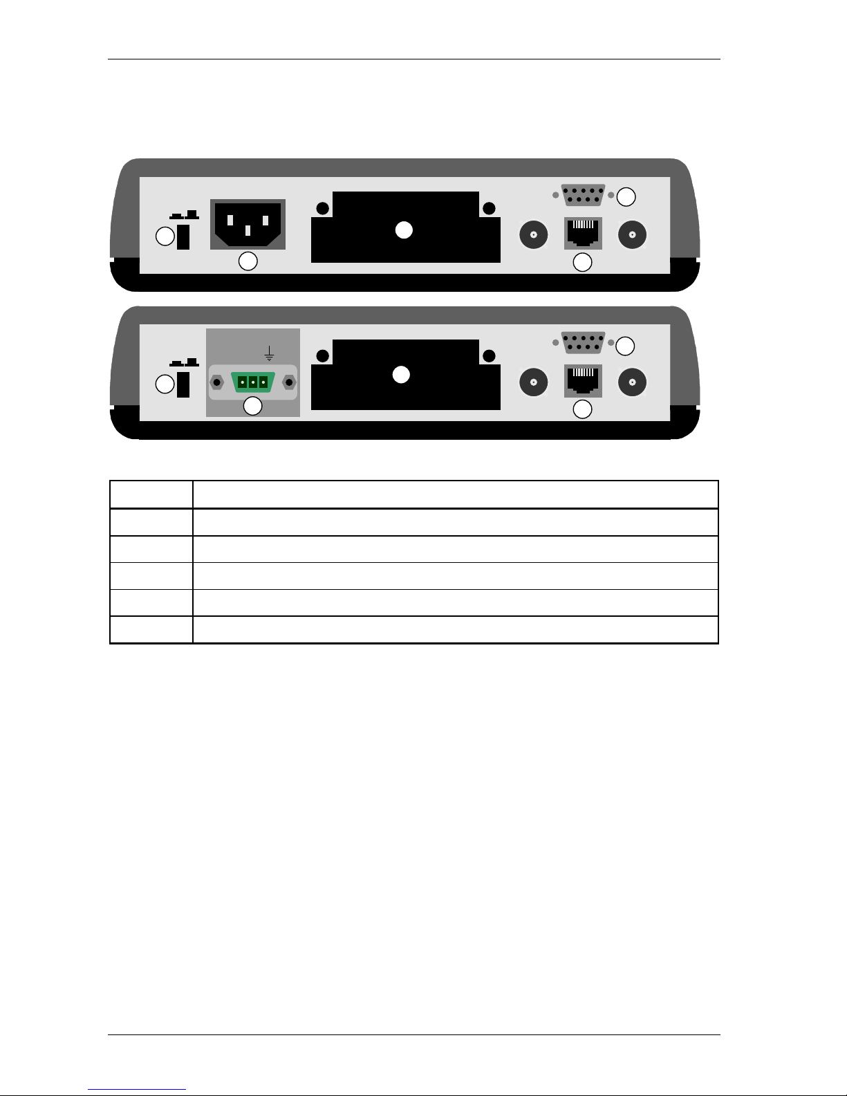
All the connections have to be made at the back of the Crocus CNV Table Top. The following figure gives
a rear view of the Crocus CNV TT.
The following table labels the different parts located at the back of the Crocus CNV TT.
Number Part
1 power switch
2 power inlet
3 DTE interface slot
4 G703 onboard interface
5 auxiliary connector (also called control or NMS connector)
CTRL
OUT IN
WARNING! SEE BOTTOM
PWR
ON OFF
CTRL
OUT IN
WARNING! SEE BOTTOM
PWR
ON OFF
~ ~
- 48V +
1
1
2
3
4
5
2
3
4
5
Page 25
Crocus CNV Installing and connecting the Crocus CNV
User manual 15
2.5.2 Connecting the power supply
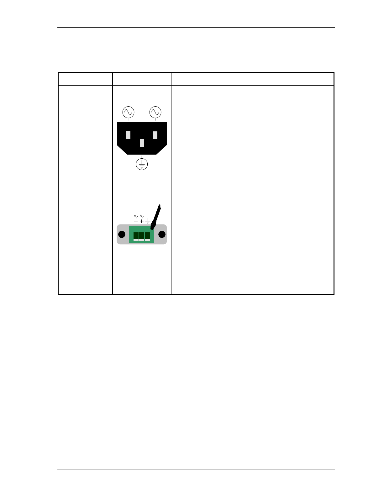
The following table explains how to connect the power supply. The Crocus CNV TT exists in two different
models:
TT model Connector type Connecting the power supply
230/115 Vac standard IEC
power supply
connector
For a 230/115 Vac model, connect the standard IEC power
supply connector to the power inlet. Refer to Section 2.5.1
Table Top connections.
-48 Vdc or 48 Vac 48 V power supply
connector
For a 48 V model, a power supply connector is delivered
with the Crocus CNV:
• For a –48 Vdc connection, the + and - indications are
with respect to each other, not to ground level. This
means that for a standard -48 Vdc connection, the
ground has to be connected to +, while the negative
voltage has to be connected to the -.
• For a 48 Vac connection, the power supply has to be
attached to the connectors indicated with ~.
When the 48 V power supply connector is wired, connect it
to the power inlet. Refer to Section 2.5.1 Table Top
connections.
Page 26

Installing and connecting the Crocus CNV Crocus CNV
16 User manual
2.5.3 Signal and protective ground interconnection
You can configure the interconnection between signal ground and protective ground (earth). Do this by
means of the appropriate strap located on the Crocus CNV TT motherboard. For more information, refer
to Section 3.1.3 - Straps of the Table Top.
Page 27
Crocus CNV Installing and connecting the Crocus CNV
User manual 17
2.5.4 Inserting the DTE interface in the Table Top
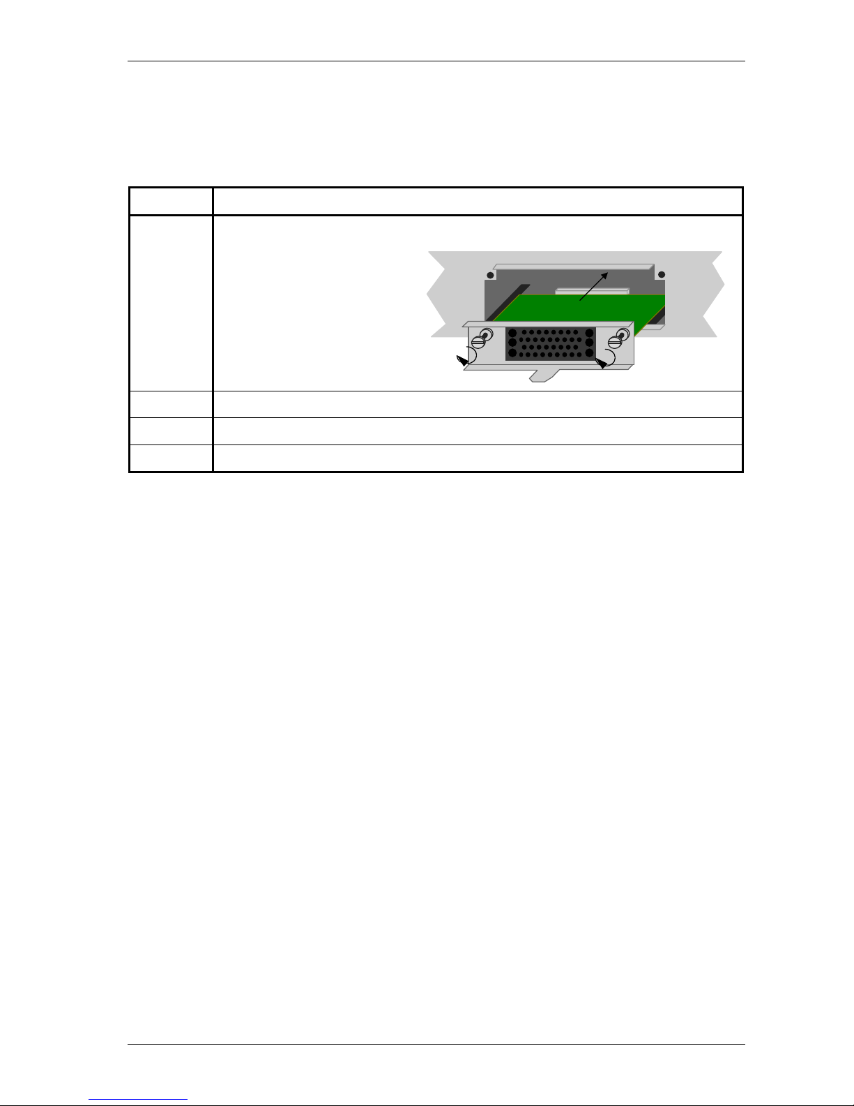
At the back of the TT, an empty slot is provided in which you can insert the desired DTE interface module
without opening the housing.
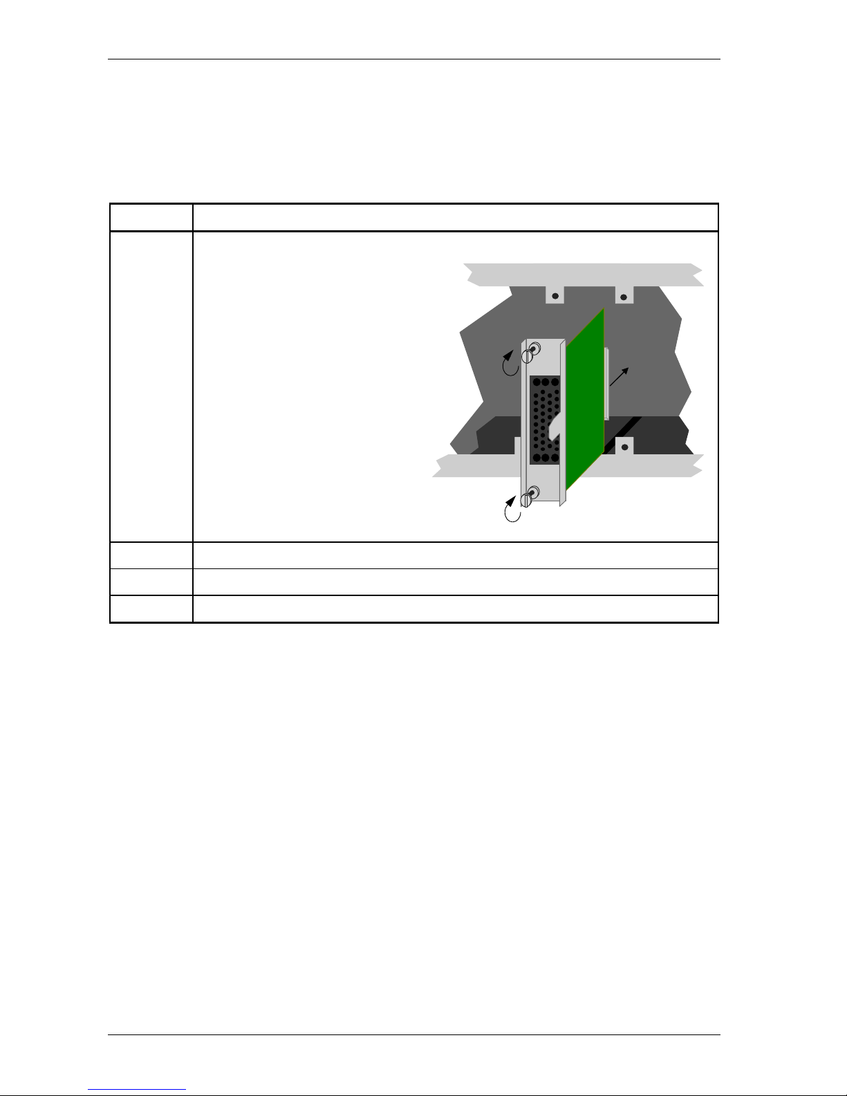
To insert the DTE interface in the TT, proceed as follows:
Step Action
1 Gently slide the DTE interface on the two inner slides into the empty slot.
The following figure shows this
procedure:
2 When nearly inserted, press tight.
3 Lock both screws.
4 When the DTE interface is present, connect the application.
Page 28

Installing and connecting the Crocus CNV Crocus CNV
18 User manual
2.6 Connecting the Crocus CNV Card Version
This section explains how to connect the Crocus CNV CV. The following table gives an overview of this
section.
Section Title Page
2.6.1 Inserting the Card Version in the CN4 card nest 19
2.6.2 Inserting the modular DTE interface in the Card Version 20
2.6.3 Connecting to the onboard G703 using the RJ45 or line connector block 21
2.6.4 Connecting to the onboard G703 through the line connector block 23
Page 29
Crocus CNV Installing and connecting the Crocus CNV
User manual 19
2.6.1 Inserting the Card Version in the CN4 card nest
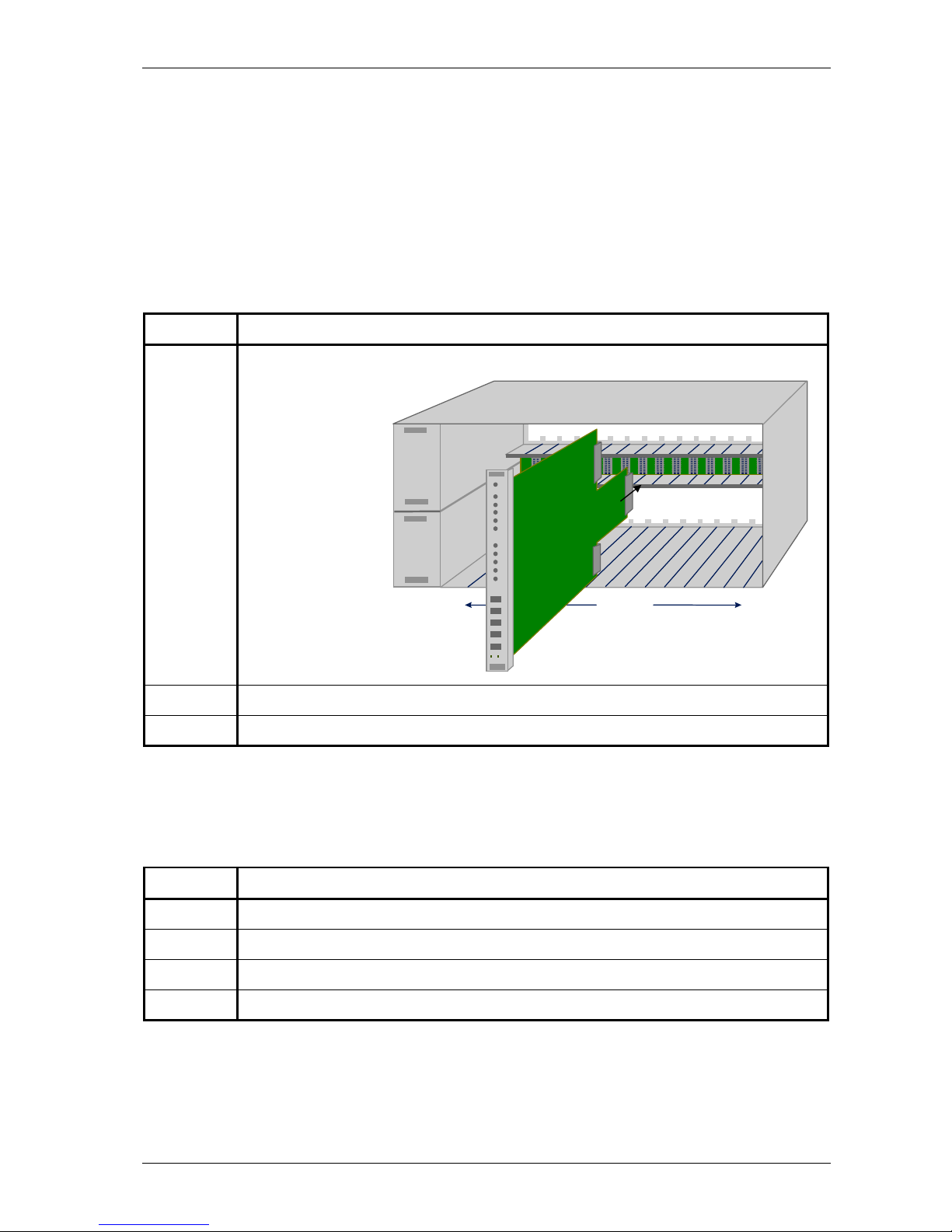
The Crocus CNV CV consists of a stuffed print, provided with a front panel. The CV has to be inserted in
the CN4 card nest. Most connections to this card are performed via 3 DIN-connectors on the back of the
card:
• the middle connector for power supply, line and management connections
• the two extreme connectors for interface connections.
Inserting the CV in the CN4 card nest
To insert the CV in the CN4 card nest, proceed as follows:
Step Action
1 Gently slide the CV on the two inner slides into an available slot.
The following figure
shows this procedure:
2 When nearly inserted, press tight.
3 Lock both screws.
Filling an entire CN4 card nest
For EMC reasons the cards all fit closely to each other. Therefore, you will experience that inserting the
last card in a completely filled up rack happens to be more stiffly. To fill up an entire rack, it is best to
proceed as follows:
Step Action
1 Insert card 1 up to 14 in slot 0 up to 13 of the CN4 card nest.
2 Fasten the screws of card 1 up to 14.
3 Insert the last card in slot 14 of the CN4 card nest.
4 Fasten the screws of the last card.
15 slots
Page 30
Installing and connecting the Crocus CNV Crocus CNV
20 User manual
2.6.2 Inserting the modular DTE interface in the Card Version
At the back of the CN4 card nest, two empty slots are provided in which the desired modular DTE
interface can be inserted without extracting the card from the card nest. The upper interface slot is used
for converter A and the lower interface slot is used for converter B.
To insert the modular DTE interface in the CN4 card nest, proceed as follows:
Step Action
1 Gently slide the modular DTE interface on the two inner slides into an available slot.
The following figure shows this procedure:
2 When nearly inserted, press tight.
3 Lock both screws.
4 When the modular DTE interface is present, connect the application.
Page 31
Crocus CNV Installing and connecting the Crocus CNV
User manual 21
2.6.3 Connecting to the onboard G703 using the RJ45 or line connector block
You can connect to the onboard G703 interface through …
• the RJ45 connector located at the front of the Crocus CNV CV
or
• the line connector block located at the back of the CN4 card nest.
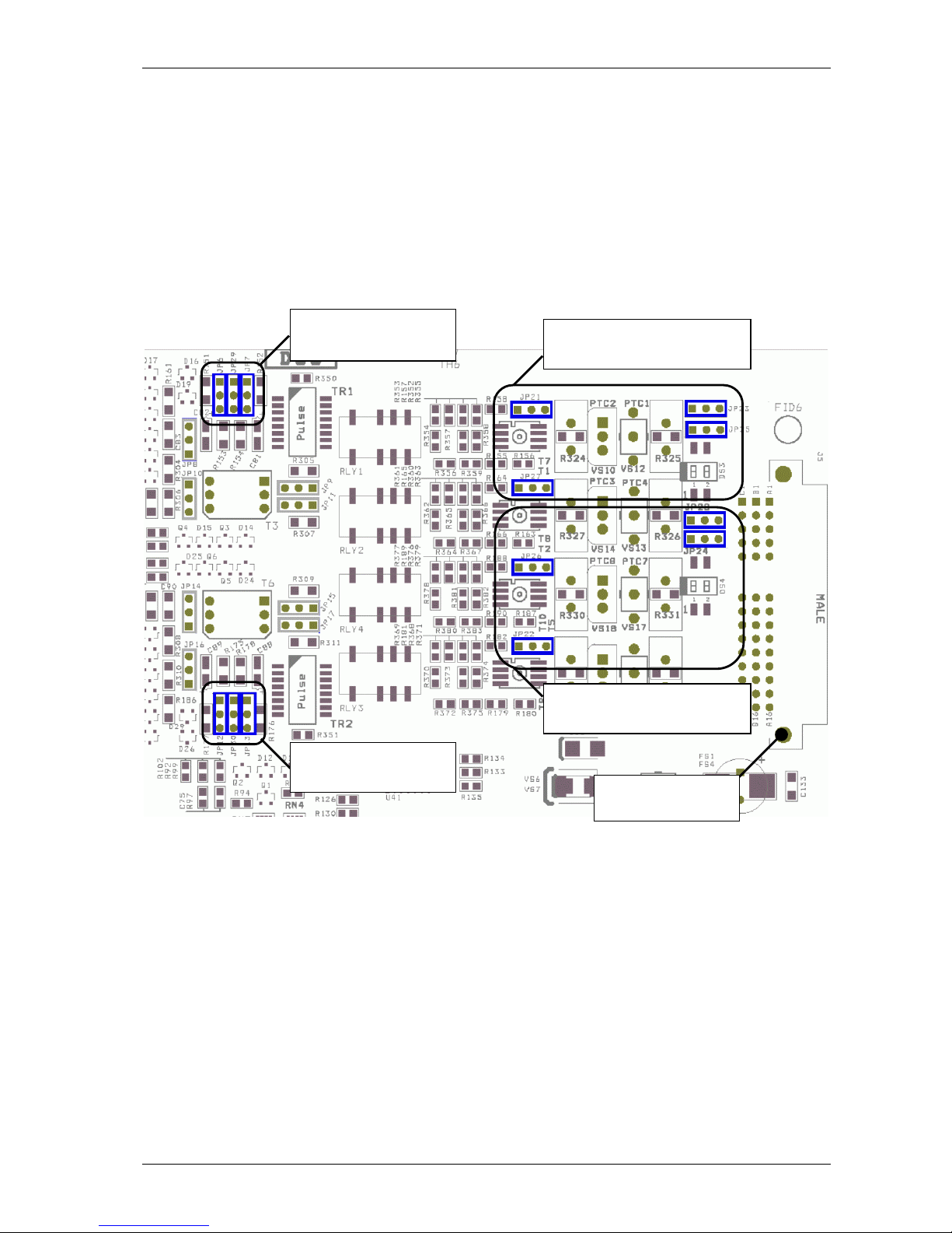
You can make this selection by means of 8 straps located on the Crocus CNV CV motherboard. This is
described in the paragraphs below.
The location of the straps on the Crocus CNV CV motherboard
strap JP21, JP23, JP25, JP27
(converter A)
strap JP12, JP13, JP30
(converter B)
strap JP6, JP7, JP29
(converter A)
middle connector
towards CN4
strap JP22, JP24, JP26, JP28
(converter B)
Page 32
Installing and connecting the Crocus CNV Crocus CNV
22 User manual
Strap JP21 – JP28 settings
You can make the RJ45 / line connector block selection for converter A and B separately:
• JP21, JP23, JP25, JP27 makes the selection for converter A
• JP22, JP24, JP26, JP28 makes the selection for converter B.
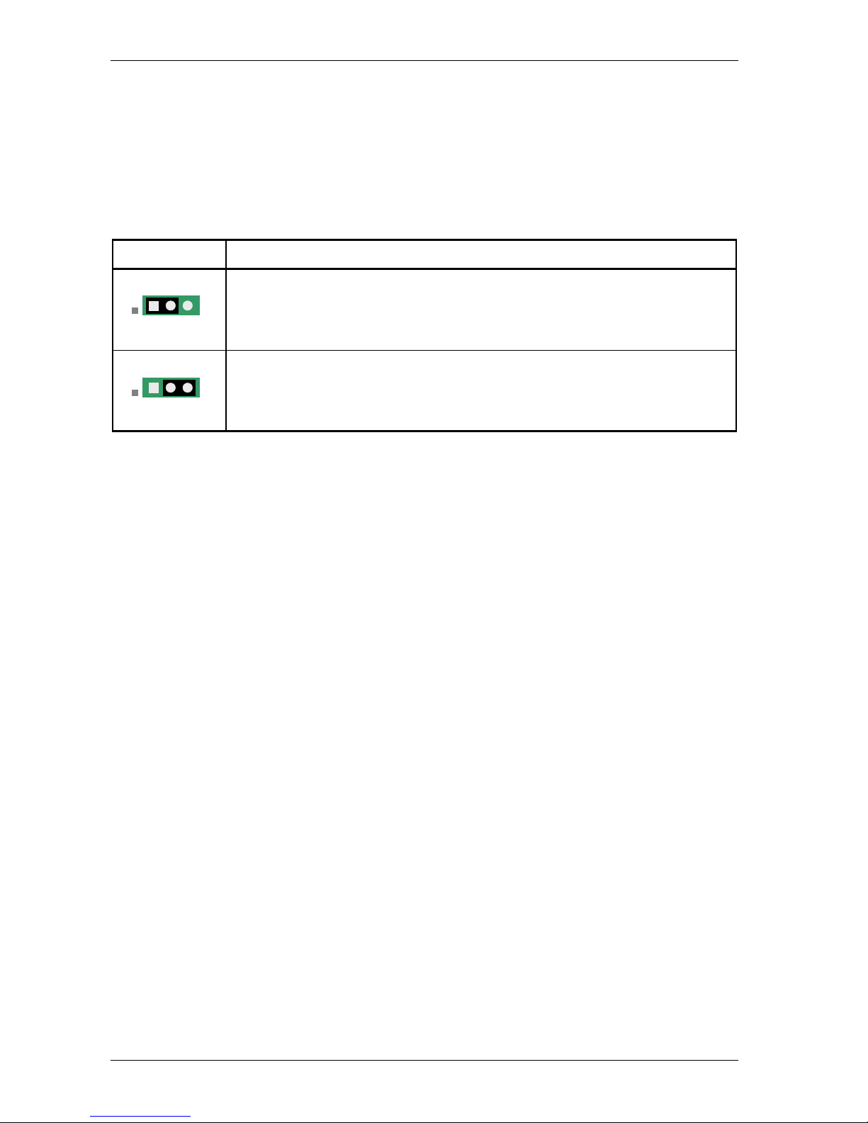
The following table shows how to set JP21 up to JP28 in order to select between the RJ45 connector or
the line connector block.
Strap setting You can connect to the onboard G703 interface through …
1 – 2 (default)
the RJ45 connector located at the front of the Crocus CNV CV.
2 – 3
the line connector block located at the back of the CN4 card nest. Refer to Section
2.6.4 - Connecting to the onboard G703 through the line connector block for more
information.
1 2 3
1 2 3
Page 33
Crocus CNV Installing and connecting the Crocus CNV
User manual 23
2.6.4 Connecting to the onboard G703 through the line connector block
It is possible to connect to the onboard G703 interface through the line connector block instead of
through the RJ45 connectors (as explained in Section 2.6.3 - Connecting to the onboard G703 using the
RJ45 or line connector block).
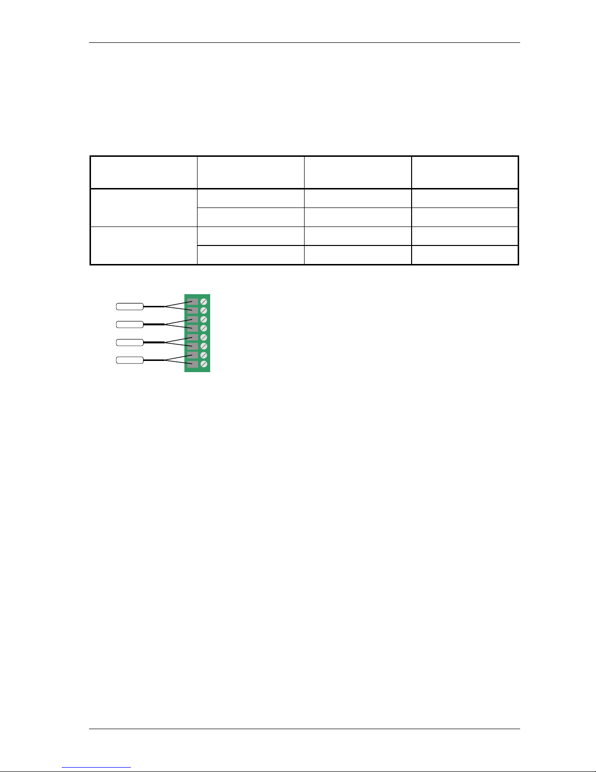
The following table explains how to connect the wires to the line connector block located at the back of
the CN4 card nest:
Converter no. RX / TX Line connector block
positions
DTE
receive 1 and 2 input converter A
transmit 3 and 4 output
receive 5 and 6 input converter B
transmit 7 and 8 output
The following figure gives a graphical representation of the table above:
1
RX-A
2
3
4
5
6
7
8
TX-A
RX-B
TX-B
Page 34
Installing and connecting the Crocus CNV Crocus CNV
24 User manual
2.7 Connecting the interfaces of the Crocus CNV
The DTE/DCE definition of the Crocus CNV interfaces is as follows:
Interface DTE / DCE Interconnection cable
onboard G703 DTE To connect this interface to …
• a DTE device, use a crossed interconnection cable.
• a DCE device, use a straight interconnection cable.
modular DCE To connect this interface to …
• a DTE device, use a straight interconnection cable.
• a DCE device, use a crossed interconnection cable.
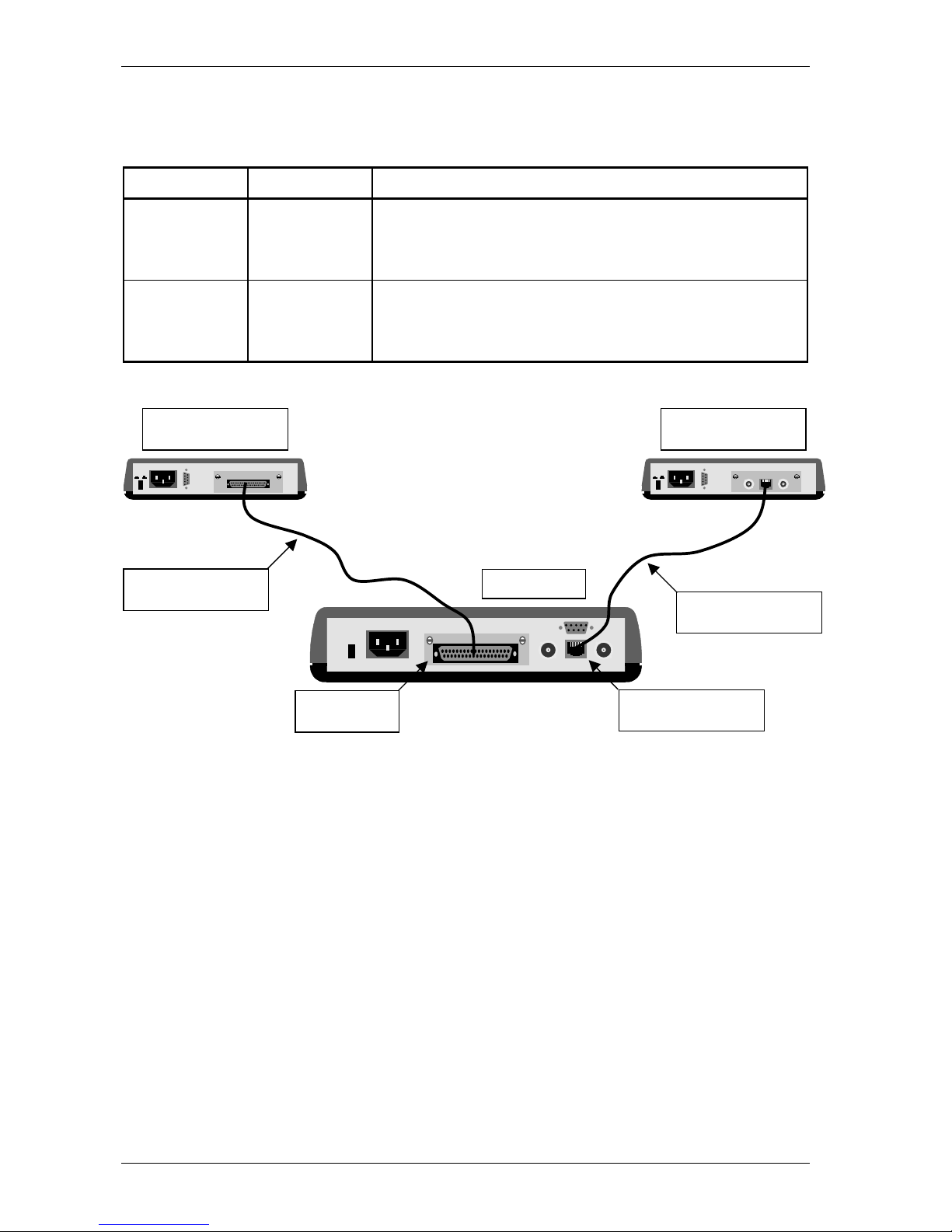
The following figure shows an example of a set-up with a Crocus CNV:
modem + G703 interface
(DCE)
Crocus CNV
modem + V36 interface
(DCE)
modular interface
(DCE)
straight
interconnection cable
crossed
interconnection cable
onboard G703 interface
(DTE)
Page 35

Crocus CNV Installing and connecting the Crocus CNV
User manual 25
2.8 Front panel LED indicators
This section gives an overview of the front panel LEDs and what they indicate The following table gives
an overview of this section.
Section Title Page
2.8.1 Introduction to the front panel LEDs 26
2.8.2 Power LED 27
2.8.3 Test LED 27
2.8.4 Alarm Indication Signal / error LED 27
2.8.5 Loss Of Signal / Loss of Frame Alignment LED 28
2.8.6 Transmit data LED 28
2.8.7 Receive data LED 28
Page 36
Installing and connecting the Crocus CNV Crocus CNV
26 User manual
2.8.1 Introduction to the front panel LEDs
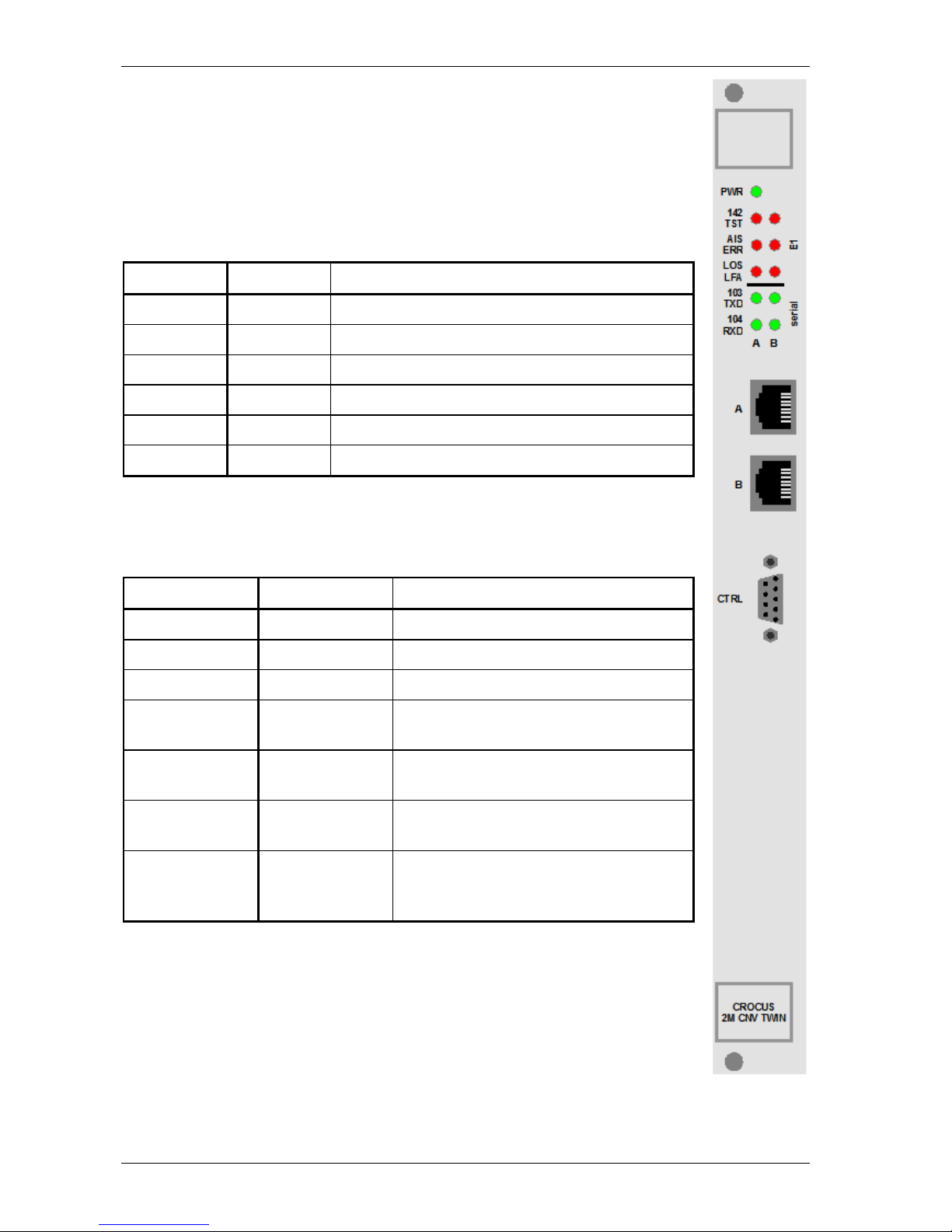
When all the connections are made and the Crocus CNV is powered, the LEDs on the
front panel reflect the actual status of the device.
LED label and colour
The following table lists the front panel LED indicators with their corresponding label and
colour.
Label Colour Short description
PWR green Power indication.
142 TST red Test indication.
AIS ERR red Alarm Indication Signal / error indication.
LOS LFA red Loss Of Signal / Loss of Frame Alignment indication.
103 TXD green Transmit data indication.
104 RXD green Receive data indication.
LED status modes
For some front panel LED indicators different status modes exist. These status modes
can be distinguished by the way the LED is lit up:
LED status LED duty cycle Description
continuously off 0 % The LED never lights up.
continuously on 100 % The LED lights up continuously.
blinking 50 % The LED is as much lit as it is out.
flashing 20 % The LED only lights up during 20% of the
time.
mostly off - The LED occasionally lights up, without a
fixed duty cycle.
mostly on - The LED occasionally goes out, without a
fixed duty cycle.
monitoring - The LED lights up irregularly. For instance,
it lights up on detection of a certain signal.
I.e. it monitors this signal.
Page 37

Crocus CNV Installing and connecting the Crocus CNV
User manual 27
2.8.2 Power LED
This LED indicates that the Crocus CNV is connected to the power supply and is switched on.
2.8.3 Test LED
This LED indicates whether the Crocus CNV is in normal operation or in test condition (ET, AL, RDL, DL
or a combination of them). Four different test LED status modes can be distinguished:
LED status Description
off No test is active.
continuously on A front panel or interface test is active.
blinking A test initiated by the management system is active.
flashing A front panel or interface test has been terminated by the management system.
Termination of an active test by the management system is necessary to prevent hang-up situations
caused by accidental activation of a test. Once the test indicator starts flashing, all active test conditions
should be removed first, before initiating a new test session.
2.8.4 Alarm Indication Signal / error LED
This LED indicates an error has occurred. The errors have different priority levels. I.e. when two errors of
different origin occur at the same time, one error will get priority over the other error. The different AIS /
error LED status modes and error priorities are displayed in the following table:
LED status Description Error priority
off No error has occurred. -
continuously on An Alarm Indication Signal (AIS) has been detected on the
incoming G.704 transmit data of the onboard G703 interface.
This means that the application has detected an error, and it
communicates this to the interface by setting all data bits to 1
(which is the AIS condition).
high
monitoring The Crocus CNV its internal error test pattern generator /
detector (ET) is active and received bit errors.
medium
flashing Alarm signalling is active and a local alarm has been detected.
For more information on alarm signalling, refer to Section 6.2 -
General configuration attributes.
low
l
Page 38
Installing and connecting the Crocus CNV Crocus CNV
28 User manual
2.8.5 Loss Of Signal / Loss of Frame Alignment LED
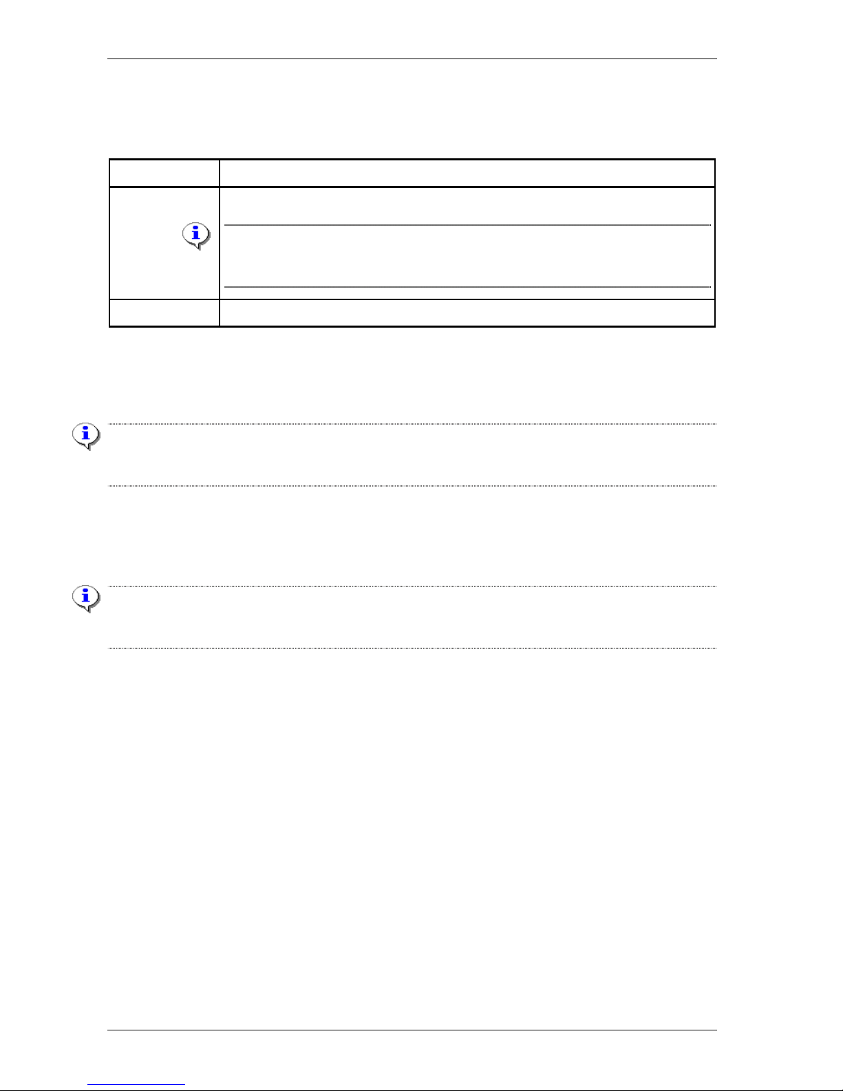
This LED indicates a Loss Of Signal or Loss of Frame Alignment has occurred. The different LOS / LFA
LED status modes are displayed in the following table:
LED status Description
continuously on A Loss Of Signal has been detected on the onboard G703 interface.
If the configuration attribute longHaul is set to enabled, then it is possible that the LOS
LED does not light up although no cable is connected to the front RJ45 connector.
This problem does not exist when using the rear line connector block.
blinking A Loss of Frame Alignment has been detected on the onboard G703 interface.
l
2.8.6 Transmit data LED
This LED monitors the data sent by the application (i.e. the Data Terminal Equipment) to the DTE
interface module of the Crocus CNV.
Note that the data is monitored after it went through the interface circuitry. Some interfaces (Bridge and
Router) add framing information which activates the TXD LED even if no real user data is being
transmitted.
2.8.7 Receive data LED
This LED monitors the data sent to the application (i.e. the Data Terminal Equipment) by the DTE
interface module of the Crocus CNV.
Note that the data is monitored before it went through the interface circuitry. Some interfaces (Bridge and
Router) used on the remote side add framing information which activates the RXD LED even if no real
user data is being received.
Page 39

Crocus CNV DIP switches and straps of the Crocus CNV
User manual 29
3 DIP switches and straps of the Crocus CNV
This chapter locates the DIP switches and straps on the Crocus CNV TT and CV motherboard. It also
gives an overview of their function and it explains how to change their settings.
The following table gives an overview of this chapter.
Section Title Page
3.1 DIP switches and straps of the Crocus CNV Table Top 30
3.2 DIP switches and straps of the Crocus CNV Card Version 36
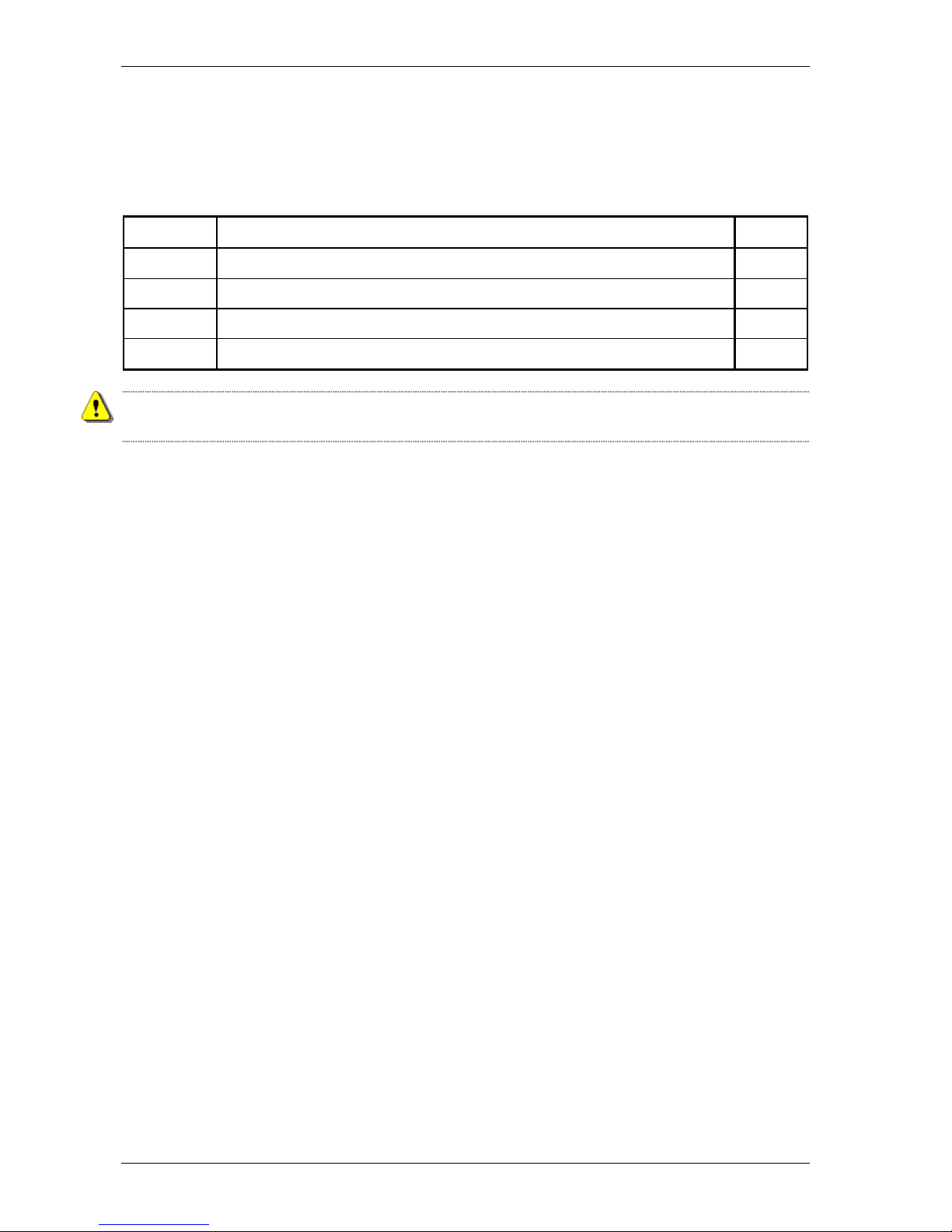
Default settings are printed in bold.
Page 40
DIP switches and straps of the Crocus CNV Crocus CNV
30 User manual
3.1 DIP switches and straps of the Crocus CNV Table Top
This section locates the DIP switches and straps on the Crocus CNV Table Top motherboard. It gives an
overview of their function and it explains how to change their settings.
The following table gives an overview of this section.
Section Title Page
3.1.1 Location of the DIP switches and straps on the Table Top 31
3.1.2 DIP switches of the Table Top 32
3.1.3 Straps of the Table Top 33
3.1.4 Changing DIP switch and strap settings of the Table Top 35
Disconnect the Crocus CNV Table Top from the mains before opening the housing to change DIP switch
and/or strap settings.
Page 41
Crocus CNV DIP switches and straps of the Crocus CNV
User manual 31
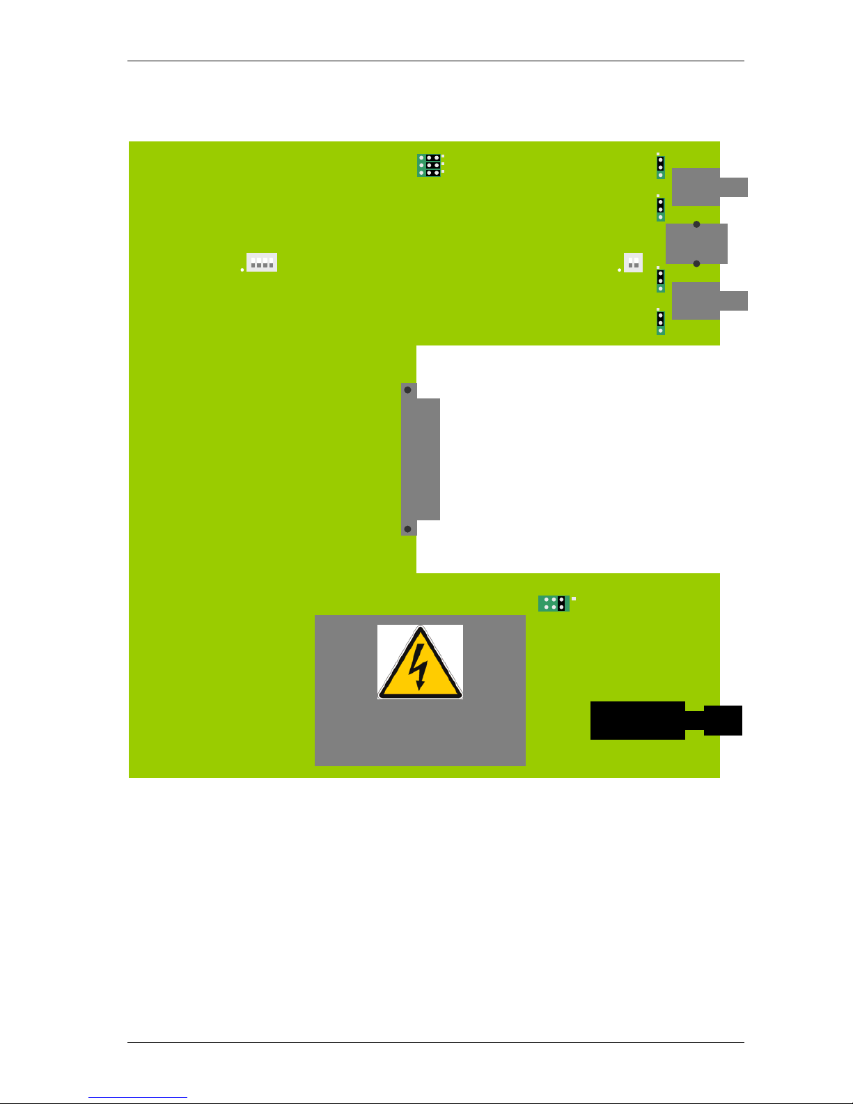
3.1.1 Location of the DIP switches and straps on the Table Top
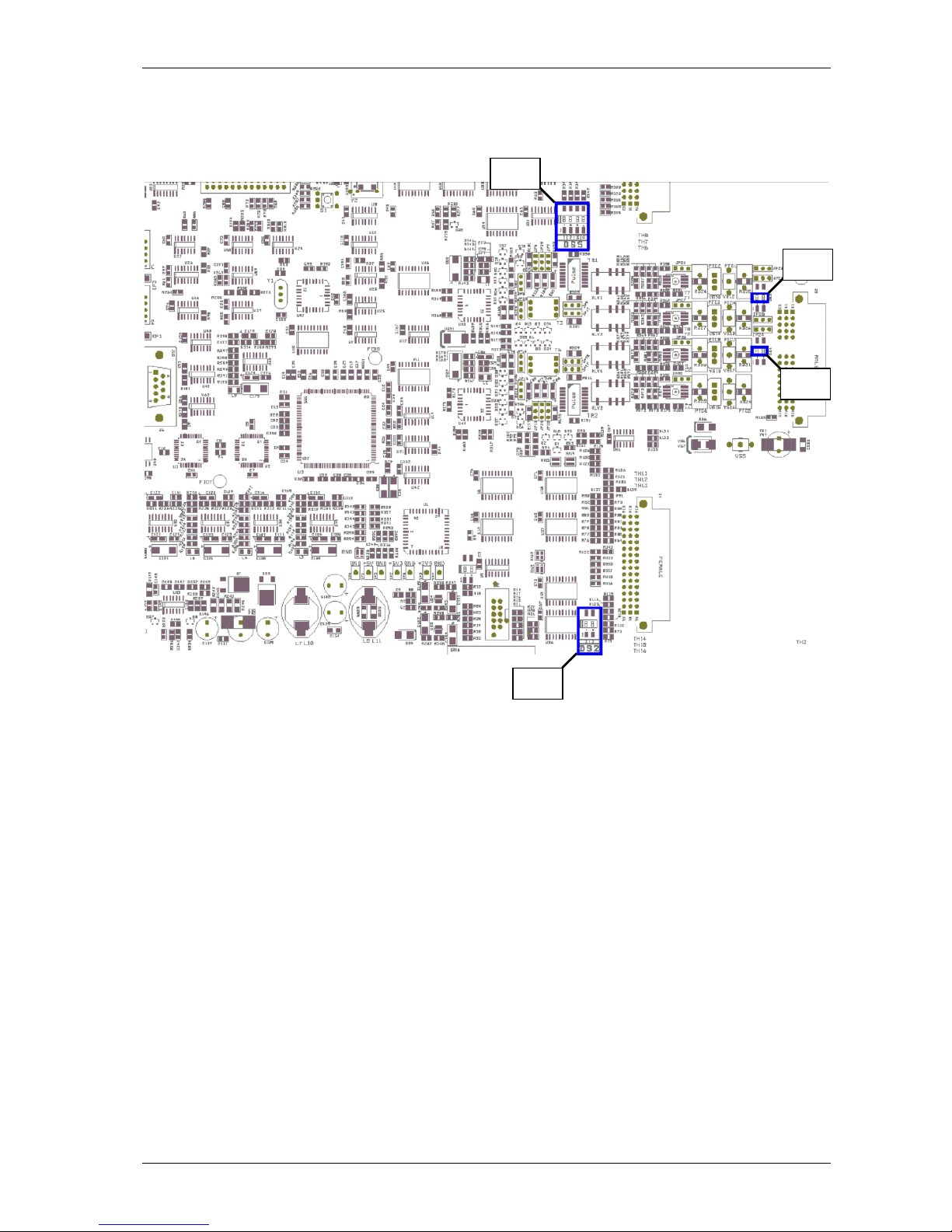
The figure below shows the position of the DIP switches and straps on the Crocus CNV TT motherboard.
DS5
ON
1 2 3 4
ST1
3 2 1
3. CON
2. CON 100R
1. NOT CON
DANGEROUS VOLTAGE AREA!
DS3
ON
1 2
JP29
3 2 1
JP7
JP6
JP23
3 2 1
JP21
3 2 1
JP25
3 2 1
JP27
3 2 1
Page 42
DIP switches and straps of the Crocus CNV Crocus CNV
32 User manual
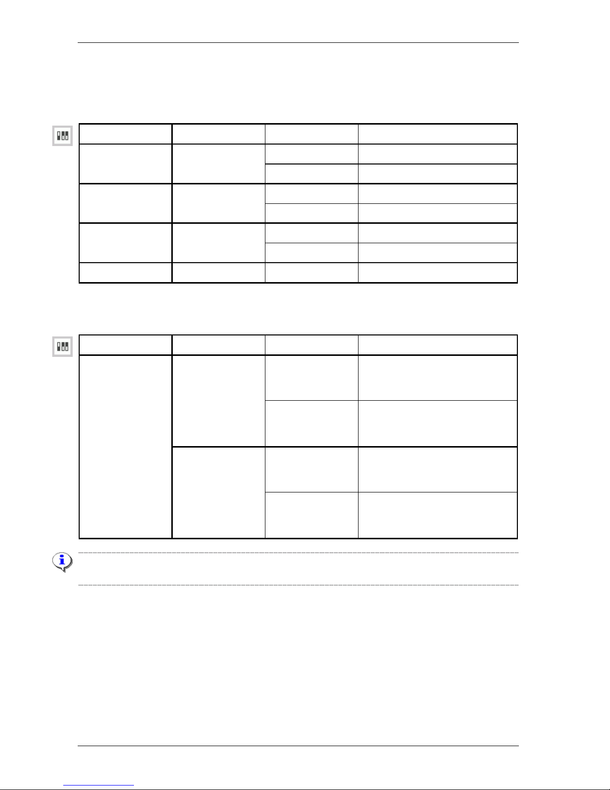
3.1.2 DIP switches of the Table Top
DIP switch bank DS5
The following table gives an overview of DIP switch bank DS5 of the TT:
DIP switch name DS5 no. Setting Function
on
Start up from flash memory.
start-up mode 1
off Start up in boot mode.
on
Normal operation.
load default
configuration
2
off Load default configuration.
on
Inverted X21 Tx clock polarity.
X21 Tx clock
polarity inversion
3
off Normal X21 Tx clock polarity.
- 4 - - Factory setting. Do not change! -
DIP switch bank DS3
The following table gives an overview of the DIP switches on DIP switch bank DS3:
DIP switch name DS3 no. Setting Function
on The receive B signal (RxB) of the
onboard G703 interface is
connected to the earth.
1
off
The receive B signal (RxB) of the
onboard G703 interface is
disconnected from the earth.
on The transmit B signal (TxB) of the
onboard G703 interface is
connected to the earth.
signal B – earth
(PGND) connection
2
(1)
off
The transmit B signal (TxB) of the
onboard G703 interface is
disconnected from the earth.
(1)
DS3 switch 2 only has effect on the RJ45 connector. For the BNC connectors, the transmit B signal is
always connected to the earth.
Page 43
Crocus CNV DIP switches and straps of the Crocus CNV
User manual 33
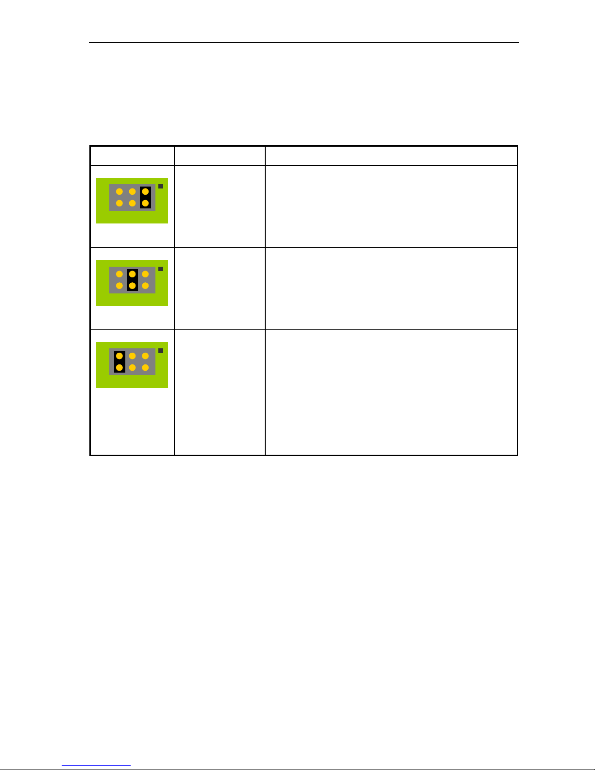
3.1.3 Straps of the Table Top
Strap ST1
On the TT, you can configure the interconnection between signal ground and protective ground (earth).
Use strap ST1 for this purpose. For the location of ST1 on the TT motherboard, refer to Section 3.1.1
Location of the DIP switches and straps on the Table Top.
Strap settings Connection Description
disconnected
As default, the signal ground is disconnected from the
earth. This avoids problems which might occur when the
earth potential of the Crocus CNV and the connected
application is not the same. In such a situation earth current
loops may induce distortion on the transmitted data,
resulting in transmission errors.
connected through
100 ohms resistor
Sometimes you might want to connect the Crocus CNV
earth to the application earth although both earth potentials
are not the same. (E.g. to avoid a big difference between
both earth potentials.) To avoid that high earth currents are
generated, you can make this connection through a 100
ohms resistor.
directly connected Sometimes it is not possible to connect the application
directly to the earth. In that case you can earth the
application through the Crocus CNV by connecting the
Crocus CNV to the earth and setting strap ST1 in position
3.
Also the opposite situation might occur: it is not possible to
earth the Crocus CNV. In that case you can earth the
Crocus CNV through the application by connecting the
application to the earth and setting strap ST1 in position 3.
3 2 1
3 2 1
3 2 1
Page 44
DIP switches and straps of the Crocus CNV Crocus CNV
34 User manual
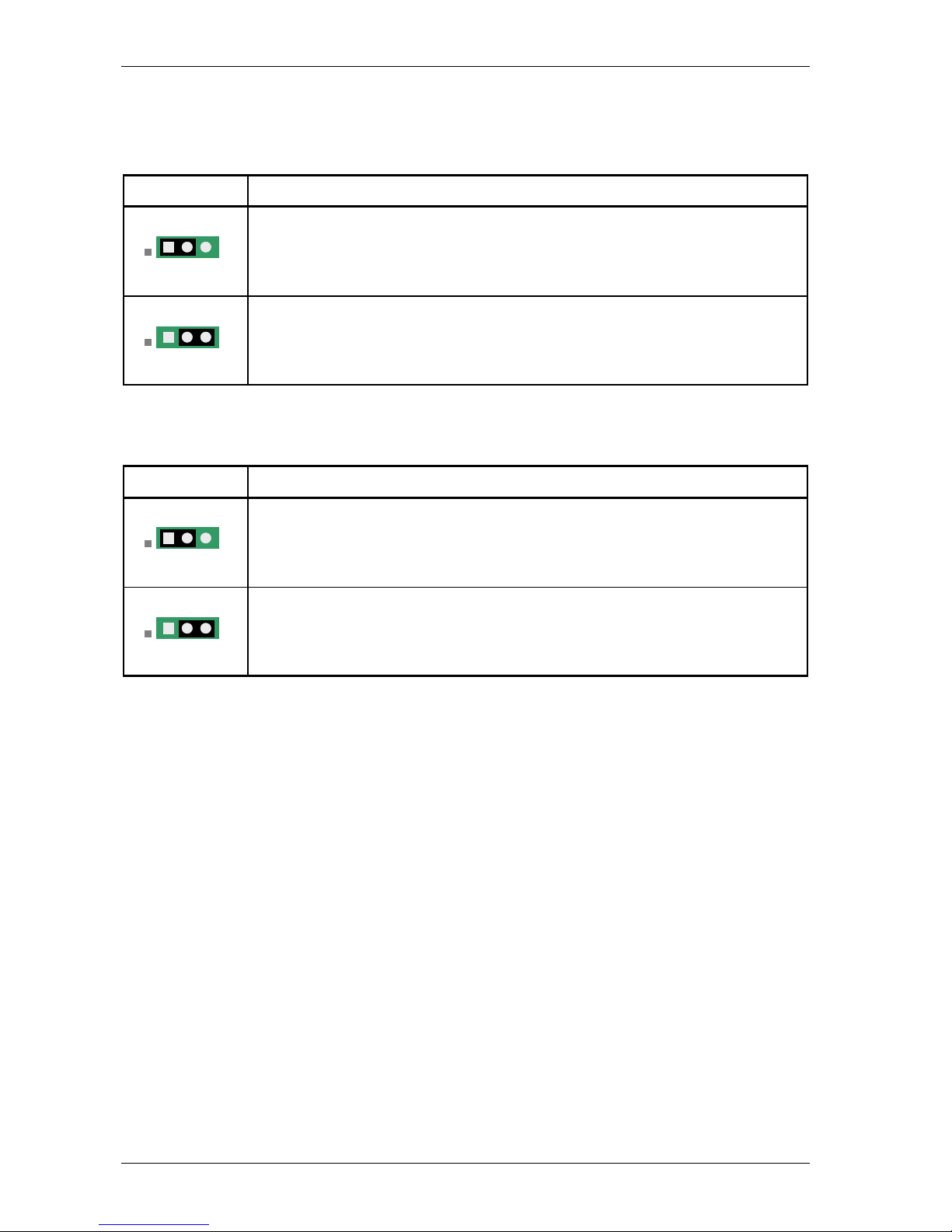
Straps JP21, JP23, JP25 and JP27
Use the straps JP21, JP23, JP25 and JP27 in order to select between the RJ45 connector or the BNC
connectors.
Strap setting You can connect to the onboard G703 interface through …
1 – 2 (default)
the RJ45 connector.
2 – 3
the BNC connectors.
Straps JP6, JP7 and JP29
Use the straps JP6, JP7 and JP29 in order to select the line impedance of the onboard G703 interface.
Strap setting The line impedance of the onboard G703 interface is …
1 – 2 (default)
120 ohm.
2 – 3
75 ohm.
1 2 3
1 2 3
1 2 3
1 2 3
Page 45
Crocus CNV DIP switches and straps of the Crocus CNV
User manual 35
3.1.4 Changing DIP switch and strap settings of the Table Top
To change the DIP switch settings of the Crocus CNV TT, proceed as follows:
Step Action
1 Switch the Crocus CNV TT off.
2 Disconnect the Crocus CNV TT from the mains.
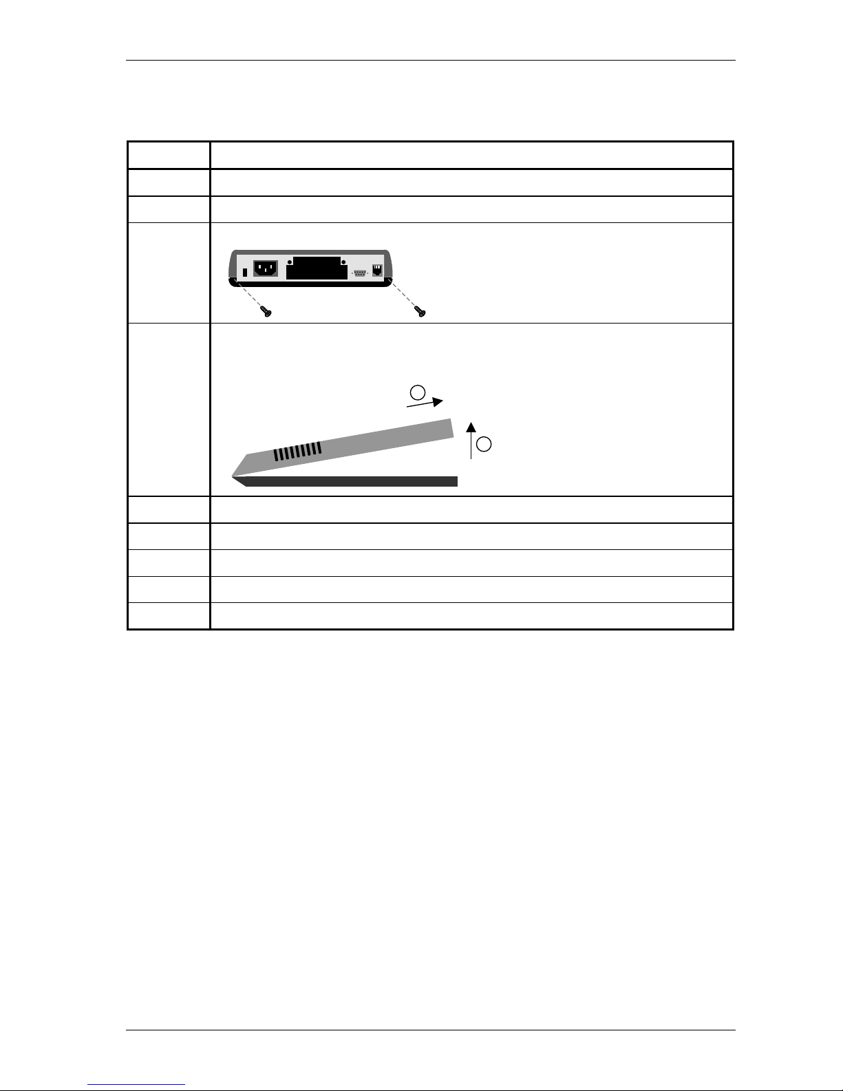
3 Unscrew the two screws located at the back of the Crocus CNV TT.
4 Remove the cover as follows:
1. Carefully lift the back of the cover a few centimetres.
2. Gently pull the cover backwards from under the nose of the Crocus CNV TT.
5 Change the DIP switch and/or strap settings.
6 Replace the cover and close tight.
7 Fasten the two screws located at the back of the Crocus CNV TT.
8 Reconnect the Crocus CNV TT to the mains.
9 Switch the Crocus CNV TT on.
1
2
Page 46

DIP switches and straps of the Crocus CNV Crocus CNV
36 User manual
3.2 DIP switches and straps of the Crocus CNV Card Version
This section locates the DIP switches and straps on the Crocus CNV Card Version motherboard. It gives
an overview of their function and it explains how to change their settings.
The following table gives an overview of this section.
Section Title Page
3.2.1 Location of the DIP switches on the Card Version 37
3.2.2 Location of the straps on the Card Version 38
3.2.3 DIP switches of the Card Version 39
3.2.4 Straps of the Card Version 41
3.2.5 Changing DIP switch and strap settings of the Card Version 42
Page 47
Crocus CNV DIP switches and straps of the Crocus CNV
User manual 37
3.2.1 Location of the DIP switches on the Card Version
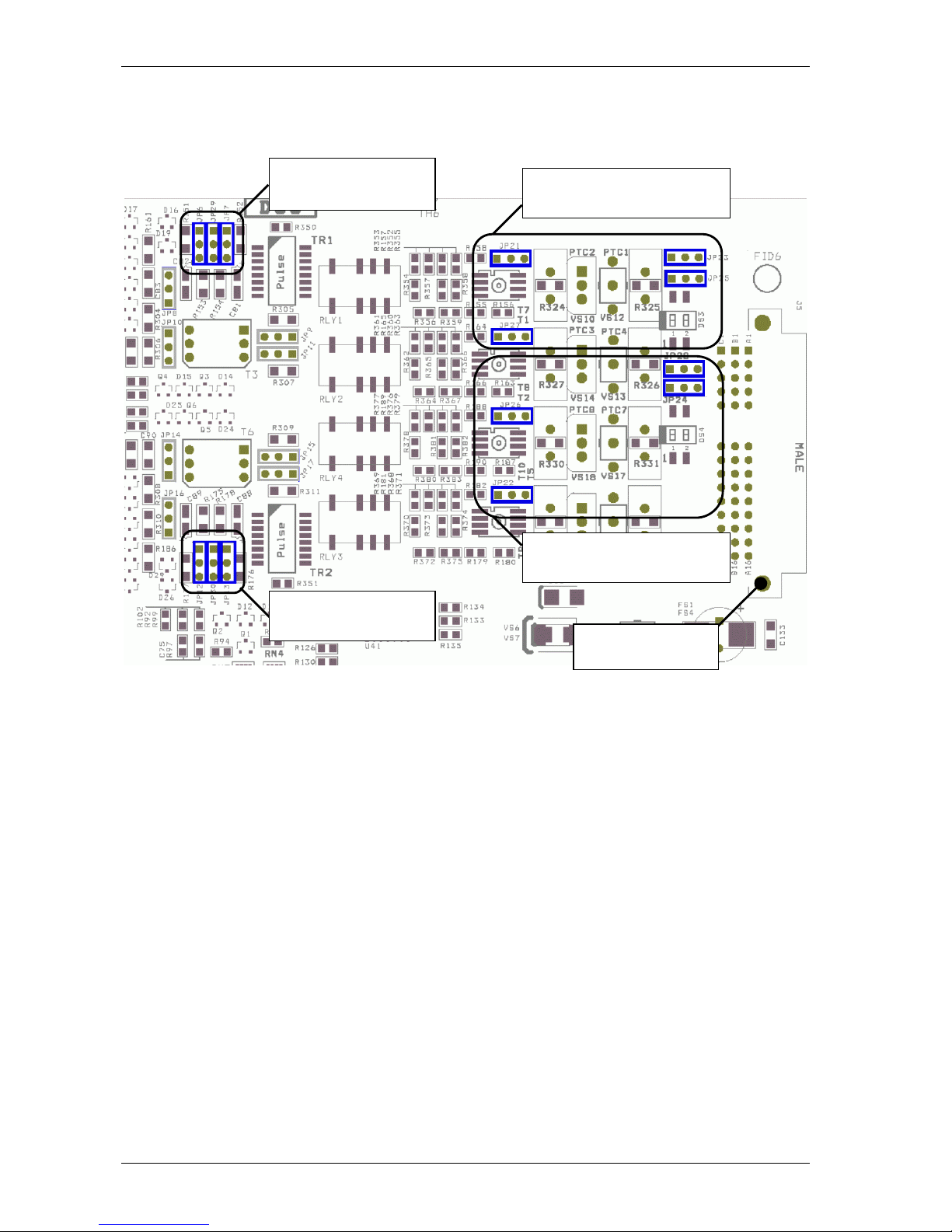
The figure below shows the position of the DIP switches on the Crocus CNV CV motherboard.
DS2
DS5
DS3
DS4
Page 48
DIP switches and straps of the Crocus CNV Crocus CNV
38 User manual
3.2.2 Location of the straps on the Card Version
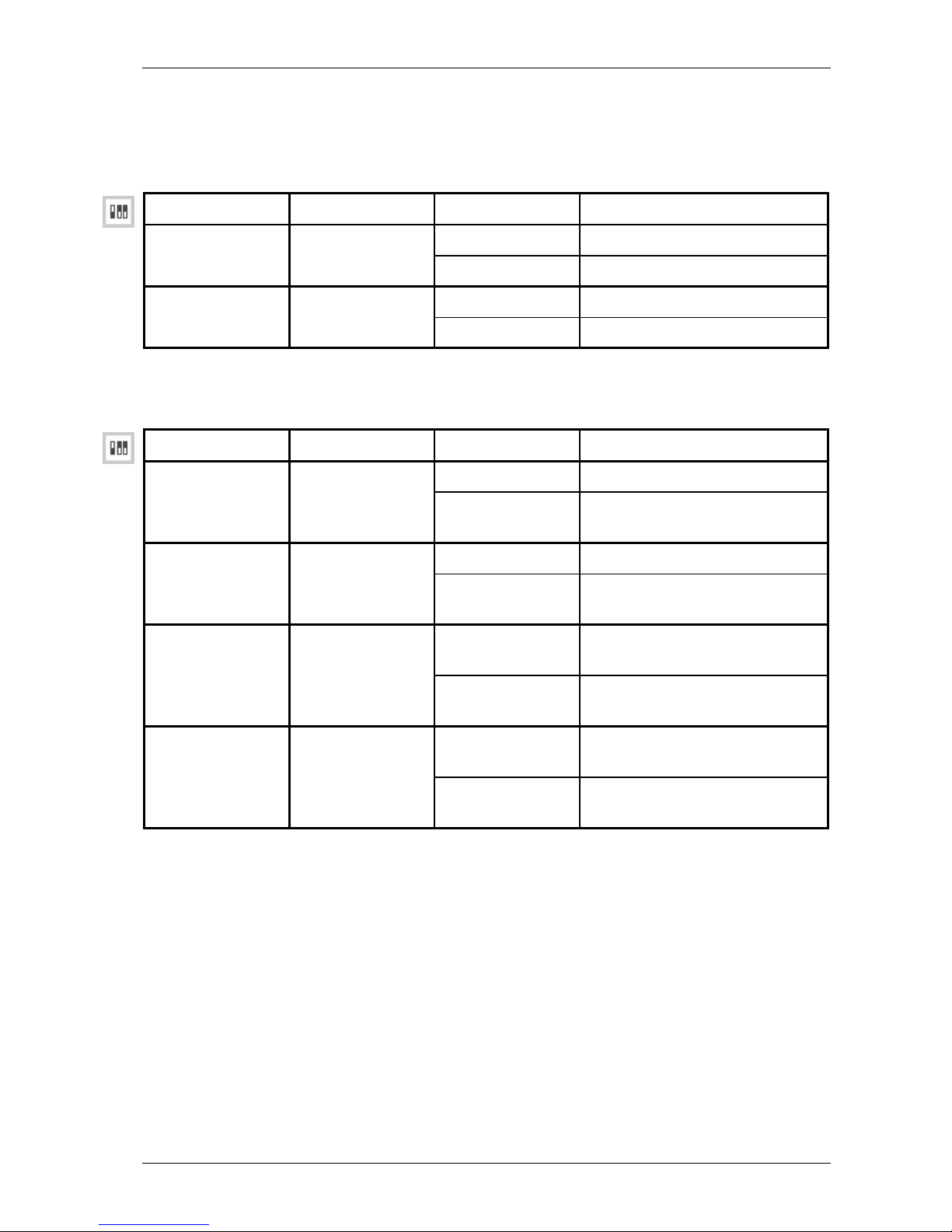
The figure below shows the position of the straps on the Crocus CNV CV motherboard.
strap JP21, JP23, JP25, JP27
(converter A)
strap JP12, JP13, JP30
(converter B)
strap JP6, JP7, JP29
(converter A)
middle connector
towards CN4
strap JP22, JP24, JP26, JP28
(converter B)
Page 49
Crocus CNV DIP switches and straps of the Crocus CNV
User manual 39
3.2.3 DIP switches of the Card Version
DIP switch bank DS2
The following table gives an overview of the DIP switches on DIP switch bank DS2:
DIP switch name DS2 no. Setting Function
1
on
Start up from flash memory. start-up mode
off Start up in boot mode.
2
on
Mandatory setting. Do not change! -
off -
DIP switch bank DS5
The following table gives an overview of the DIP switches on DIP switch bank DS5:
DIP switch name DS5 no. Setting Function
1
on
Normal operation for converter A. load default
configuration converter A
off Load default configuration for
converter A.
2
on
Normal operation for converter B. load default
configuration converter B
off Load default configuration for
converter B.
3 on Inverted X21 Tx clock polarity for
converter A.
X21 Tx clock
polarity inversion converter A
off
Normal X21 Tx clock polarity for
converter A.
4 on Inverted X21 Tx clock polarity for
converter B.
X21 Tx clock
polarity inversion converter B
off
Normal X21 Tx clock polarity for
converter B.
Page 50

DIP switches and straps of the Crocus CNV Crocus CNV
40 User manual
DIP switch bank DS3
The following table gives an overview of the DIP switches on DIP switch bank DS3:
DIP switch name DS3 no. Setting Function
on The receive B signal (RxB) of the
onboard G703 interface of
converter A is connected to the
earth.
1
off
The receive B signal (RxB) of the
onboard G703 interface of
converter A is disconnected from
the earth.
on The transmit B signal (TxB) of the
onboard G703 interface of
converter A is connected to the
earth.
signal B – earth
(PGND) connection
for converter A
2
off
The transmit B signal (TxB) of the
onboard G703 interface of
converter A is disconnected from
the earth.
DIP switch bank DS4
The following table gives an overview of the DIP switches on DIP switch bank DS4:
DIP switch name DS4 no. Setting Function
on The receive B signal (RxB) of the
onboard G703 interface of
converter B is connected to the
earth.
1
off
The receive B signal (RxB) of the
onboard G703 interface of
converter B is disconnected from
the earth.
on The transmit B signal (TxB) of the
onboard G703 interface of
converter B is connected to the
earth.
signal B – earth
(PGND) connection
for converter B
2
off
The transmit B signal (TxB) of the
onboard G703 interface of
converter B is disconnected from
the earth.
Page 51
Crocus CNV DIP switches and straps of the Crocus CNV
User manual 41
3.2.4 Straps of the Card Version
Straps JP21 Æ JP28
Use the straps JP21 up to JP28 in order to select between the RJ45 connector or the line connector
block:
• JP21, JP23, JP25, JP27 makes the selection for converter A
• JP22, JP24, JP26, JP28 makes the selection for converter B.
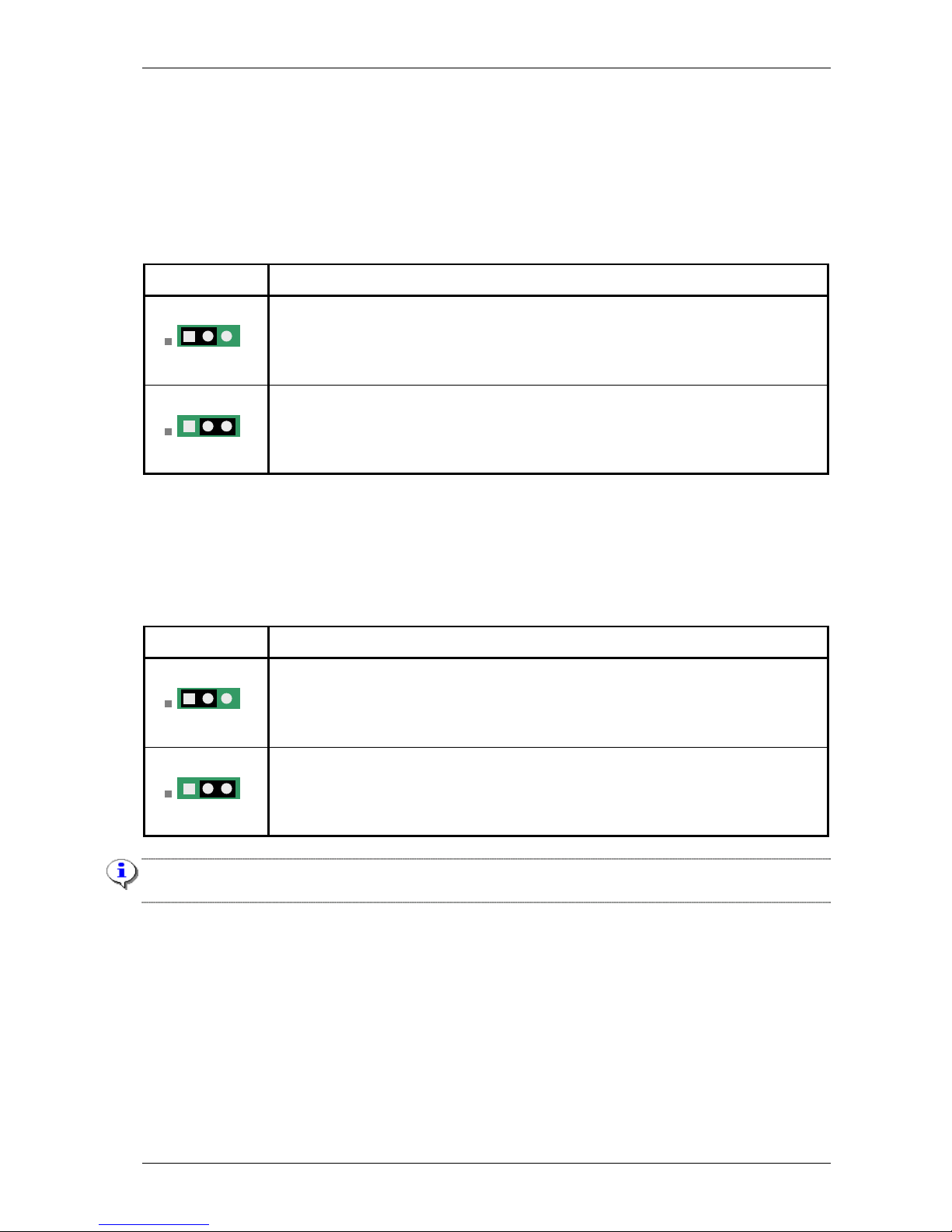
Strap setting You can connect to the onboard G703 interface through …
1 – 2 (default)
the RJ45 connector located at the front of the CV.
2 – 3
the line connector block located at the back of the CN4 card nest. For more
information, refer to Section 2.6.3 - Connecting to the onboard G703 using the
RJ45 or line connector block.
Straps JP6, JP7, JP12, JP13, JP29 and JP30
Use the straps JP6, JP7, JP12, JP13, JP29 and JP30 in order to select the line impedance of the
onboard G703 interface:
• JP6, JP7, JP29 makes the selection for converter A
• JP12, JP13, JP30 makes the selection for converter B.
Strap setting The line impedance of the onboard G703 interface is …
1 – 2 (default)
120 ohm.
2 – 3
75 ohm.
Changing the line impedance of the onboard G703 interface applies to the front RJ45 connector, as well
as to the line connector block at the back of the CN4 card nest.
1 2 3
1 2 3
1 2 3
1 2 3
Page 52

DIP switches and straps of the Crocus CNV Crocus CNV
42 User manual
3.2.5 Changing DIP switch and strap settings of the Card Version
To change the DIP switch and / or strap settings of the Crocus CNV CV, proceed as follows:
Step Action
1 Loosen the screws of the Crocus CNV.
2 Gently pull the Crocus CNV out of the CN4 card nest.
3 Change the DIP switch and / or strap settings.
4 Gently slide the Crocus CNV in the CN4 card nest.
5 Fasten the screws of the Crocus CNV.
Page 53

Crocus CNV Maintenance of the Crocus CNV
User manual 43
4 Maintenance of the Crocus CNV
Once you installed the Crocus CNV, you can proceed with the configuration of the Crocus CNV. You can
do this using the Total Maintenance Application (TMA).
This chapter introduces TMA and describes how to start a session on the Crocus CNV. Furthermore, this
chapter gives an introduction to the attributes of the Crocus CNV.
Section Title Page
4.1 Introducing TMA 44
4.2 Connecting to a Crocus CNV with TMA 45
4.3 Introducing the management attributes of the Crocus CNV 48
Page 54

Maintenance of the Crocus CNV Crocus CNV
44 User manual
4.1 Introducing TMA
TMA is a free Windows® software package that enables you to maintain the Crocus CNV, i.e. to access
its configuration attributes and look at status, performance and alarm information using a user friendly
graphical user interface.
TMA is an excellent tool for complete management of the OneAccess access devices. When using TMA
in combination with a network management system such as HP OpenView
®
, complete networks can be
managed from one central site.
Consult the TMA user manual to install it and get acquainted with the TMA user interface.
You will need a new version of the model file distribution if changes have been made to the attributes of
the Crocus CNV. The most recent model files and TMA engine can always be downloaded from the
OneAccess web site. Go to http://www.oneaccess-net.com/telindus/downloads
Î Download Center.
Page 55
Crocus CNV Maintenance of the Crocus CNV
User manual 45
4.2 Connecting to a Crocus CNV with TMA
This section explains how you can connect to the Crocus CNV using TMA.
There are two ways to establish a connection with TMA to the Crocus CNV:
• over a serial connection, through the auxiliary connector of the Crocus CNV.
• over an IP or a serial connection, through the Orchid 1003 LAN
Connecting through the auxiliary connector
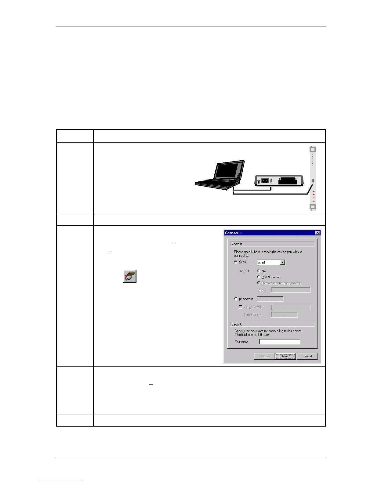
To establish a link between TMA and the Crocus CNV through the auxiliary connector, proceed as
follows:
Step Action
1 Connect the COM port of your PC through
a straight DB9 male-female cable with the
auxiliary connector of your Crocus CNV as
shown in the following figure:
2 Start TMA.
3 In the TMA window, either …
• select from the menu bar: C
onnect Æ
De
vice…
• or press the shortcut key: Ctrl+N
• or press on the Connect to device
button:
The Connect (to a device) window is being
displayed as in the following figure:
4 In the Connect (to a device) window, configure the following parameters:
• Select the option S
erial, and specify the COM port of your computer the Crocus CNV
is connected to.
• If a password has previously been configured in the Crocus CNV then also fill in the
password field.
5 If the necessary parameters are filled in, press the Next > button.
Page 56
Maintenance of the Crocus CNV Crocus CNV
46 User manual
Step Action
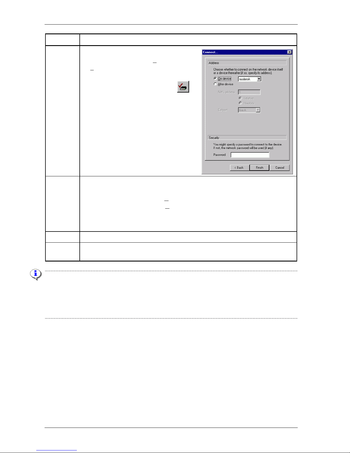
6 In the TMA window, either …
• select from the menu bar: C
onnect Æ
S
elect device…
• or press the shortcut key: Ctrl+D
• or press on the Select device button:
The Connect (select a device) window is being
displayed as in the following figure:
7 Two situations can be distinguished depending on establishing a connection to a Crocus
CNV TT or CV:
• For a Crocus CNV TT, choose O
n device.
• For a Crocus CNV CV, choose O
n device and select modem A or modem B.
If a password has previously been configured in the Crocus CNV then also fill in the
password field.
8 If the necessary parameters are filled in, press the Finish button.
9 After a couple of seconds, the attributes of the selected Crocus CNV appear in the TMA
window.
Important remark
Suppose that both modem (converter) A and B of a Crocus CNV CV have a password. In that case, if you
want to connect with TMA to converter B …
• first enter the password of converter A in the Connect device window (see step 3)
• then enter the password of converter B in the Select device window (see step 6).
Page 57

Crocus CNV Maintenance of the Crocus CNV
User manual 47
Connecting through the Orchid 1003 LAN
On central locations with many access devices, the Crocus CNV can be connected to an Orchid 1003
LAN concentrator device. In this case the Orchid 1003 LAN is a proxy device for the Crocus CNV. In that
case you can connect TMA to the Crocus CNV through the Orchid 1003 LAN.
What is more, the Orchid 1003 LAN can act as an IP proxy device for the Crocus CNV. The IP address
related to the Crocus CNV is defined in the Orchid 1003 LAN.
Refer to the manual of the Orchid 1003 LAN for more information on the configuration and management
capabilities of this device.
Page 58
Maintenance of the Crocus CNV Crocus CNV
48 User manual
4.3 Introducing the management attributes of the Crocus CNV
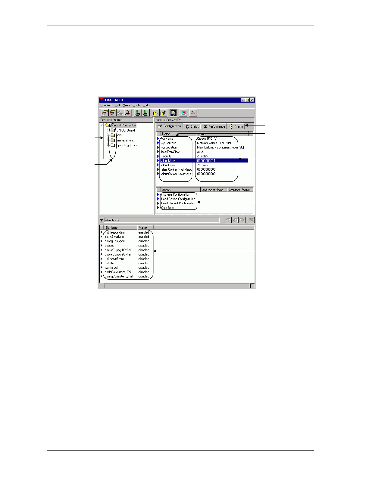
This section gives an introduction to the management attributes of the Crocus CNV. It introduces terms
such as containment tree, group, object, attribute, value and action.
Containment tree terminology
The following figure depicts the TMA window containing the Crocus CNV containment tree.
Containment tree
Structured values
Actions
Attribute values
Groups
Objects
Attributes
Page 59

Crocus CNV Maintenance of the Crocus CNV
User manual 49
The following table explains the terminology associated with the containment tree.
Term Description
containment
tree
The containment tree represents the hierarchical structure of the Crocus CNV. It is
composed of a number of objects that are ordered in a tree. This tree resembles a
Windows
®
directory structure:
• it is also a levelled structure, with nodes which can be expanded or reduced
• the containment tree objects can be compared with file folders
• the objects contain attributes like file folders contain files.
object An object represents a physical interface, an application or a combination of both.
Each object has its own set of attributes.
Example:
The top object crocusIfConv<2m/Nx64><Tt/Cv> contains the sub object g703OnBoard. This
object contains all the attributes concerning the onboard G703 interface. E.g. the
configuration attribute coding.
attribute An attribute is a parameter related to a certain object. It has a certain value.
Example:
The top object crocusIfConv<2m/Nx64><Tt/Cv> contains the bootFromFlash attribute, which
has the values auto, flash1 and flash2.
value An attribute has a certain value which is …
• changeable in case of a configuration attribute (provided you have write access)
• read only in case of a status, performance and alarm attribute.
Example:
The configuration attribute bootFromFlash can be set to the value auto, flash1 and flash2.
structured value Some attribute values contain underlying values: a structured value. These values
are displayed in the structured value window. If an attribute contains structured
values then a bit string, <Table> or <Struct> is displayed after the attribute.
Example:
The alarmLevel attribute contains a structured value which displays alarms and their
corresponding priority level.
group Groups assemble a set of attributes related by functionality. There are four groups
in TMA, which correspond with the four tabs in the attribute window:
• configuration
• status
• performance
• alarms.
action A group in combination with an object may have actions assigned to them. These
actions are displayed in the action window.
Example:
The Cold Boot action only appears when the top object crocusIfConv<2m/Nx64><Tt/Cv> is
selected in combination with the group Configuration.
Page 60

Maintenance of the Crocus CNV Crocus CNV
50 User manual
The Crocus CNV containment tree
The following table lists the different objects of the Crocus CNV containment tree.
Object This object contains …
> crocusIfConv
<2m/Nx64><Tt/Cv>
the general system attributes. It is the top object in the containment tree.
E.g. the status attribute sysUpTime: 00005d 02h 53m 16s.
Note that for the different models (2M or Nx64k) or versions (TT or CV) the top
object name differs.
>> g703OnBoard
the attributes of the onboard G703 interface.
E.g. the configuration attribute coding.
>> <dteInterface>
the attributes of the DTE interface.
E.g. the configuration attributes txClk and rxClk.
The name of this object depends on the type of DTE interface.
E.g. v35 in case of a V35 interface, rs530 in case of a RS530 interface, …
>> management
the network management attributes.
E.g. the status attribute ifSpeed.
>> operatingSystem
the operating system attributes.
E.g. the performance attribute currUsedProcPower (%).
Page 61

Crocus CNV Maintenance of the Crocus CNV
User manual 51
Where can you find an overview of all the attributes?
The reference part of this manual explains all the attributes of the Crocus CNV. One chapter describes
one group of attributes:
• chapter 6 describes the configuration attributes
• chapter 7 describes the status attributes
• chapter 8 describes the performance attributes
• chapter 9 describes the alarm attributes.
Within a chapter, the objects and their underlying attributes are discussed in a sequential manner. I.e.
from top to bottom, as they appear in the attribute window.
Page 62

Step-by-step configuration Crocus CNV
52 User manual
5 Step-by-step configuration
This chapter describes in a step-by-step method how to perform a basic configuration on Crocus CNV. It
also explains how DIP switch configuration tables and TMA attribute strings should be interpreted.
You are advised to read this chapter in a sequential manner, from the beginning to the end, without
skipping any part. By doing so, your Crocus CNV will be completely configured and ready for use when
you reach the end of this chapter.
The following table gives an overview of this chapter.
Section Title Page
5.1 Reading the configuration settings 53
5.2 Loading the default configuration 55
5.3 Configuring the clocking mode 58
5.4 Configuring the onboard G703 interface 65
5.5 Configuring the interface specific attributes 67
5.6 Configuring the management attributes 70
5.7 Activating the configuration 73
For a complete overview of the attributes of the Crocus CNV, refer to the reference manual.
Page 63
Crocus CNV Step-by-step configuration
User manual 53
5.1 Reading the configuration settings
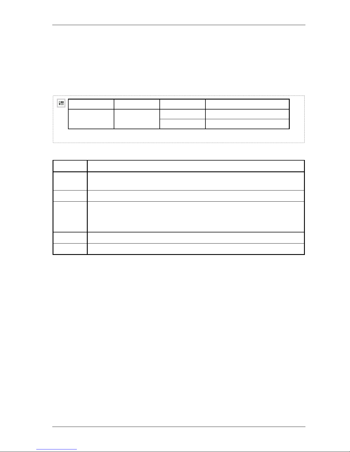
As this chapter explains the basic configuration of the Crocus CNV, it contains some DIP switch
configuration tables and a lot of TMA attribute strings. To enable you to read this information in a correct
manner, this section explains the structure of such tables and strings.
DIP switch configuration table
A DIP switch configuration table has the following layout:
DIP switch name DS2 no. Setting Function
1
on
Start up from flash memory. start-up mode
off Start up in boot mode.
1 2 3 4 5
The following table explains the DIP switch configuration table layout.
Number This position displays …
1 the DIP switch icon. It indicates that the table which follows is a DIP switch configuration
table.
2 the DIP switch name.
3 the DIP switch position on the DIP switch bank.
The abbreviations mean the following:
DS2 no. 2: DIP switch bank number 2, switch position number 2
4
the possible settings of the DIP switch: on and off. The default setting is printed in bold.
5 the function associated with the corresponding DIP switch setting.
Page 64

Step-by-step configuration Crocus CNV
54 User manual
TMA attribute string
A TMA attribute string has the following layout:
crocusIfConv<2m/Nx64><Tt/Cv>/g703OnBoard/longHaul default: enabled
1 2 3
The following table explains the TMA attribute string layout.
Number This position displays …
1 the TMA attribute icon. It indicates that the string which follows is a TMA attribute string.
Two different TMA attribute icons exist:
• a basic attribute icon
• an advanced attribute icon.
For more information refer to Preface – Conventions used in this manual.
2 the attribute name and its position in the containment tree.
In the figure above, the string crocusIfConv<2m/Nx64><Tt/Cv>/g703OnBoard/longHaul means
the following:
• the attribute name is longHaul
• this attribute is located in the sub object g703OnBoard
• this sub object is located in the top object crocusIfConv<2m/Nx64><Tt/Cv>.
3 the default value of a configuration attribute.
Page 65

Crocus CNV Step-by-step configuration
User manual 55
5.2 Loading the default configuration
If you install the Crocus CNV for the first time, all configuration attributes are set to their default value. If
the Crocus CNV has already been configured a number of times and you want to reconfigure it starting
from scratch, it might be best to load the default configuration.
Also, when you accidentally made a configuration error which, for some reason, makes the Crocus CNV
inaccessible for TMA, you can load the default configuration using the appropriate DIP switch. For
instance: you defined a password in the Crocus CNV but you can not remember it. In that case you can
not access the Crocus CNV with TMA if you do not supply the correct password.
You can load the default configuration
by means of …
For more information, refer to Section …
a DIP switch. 5.2.1 - The load default configuration DIP switch
an action in TMA. 5.2.2 - The Load Default Configuration action in TMA
Page 66
Step-by-step configuration Crocus CNV
56 User manual
5.2.1 The load default configuration DIP switch
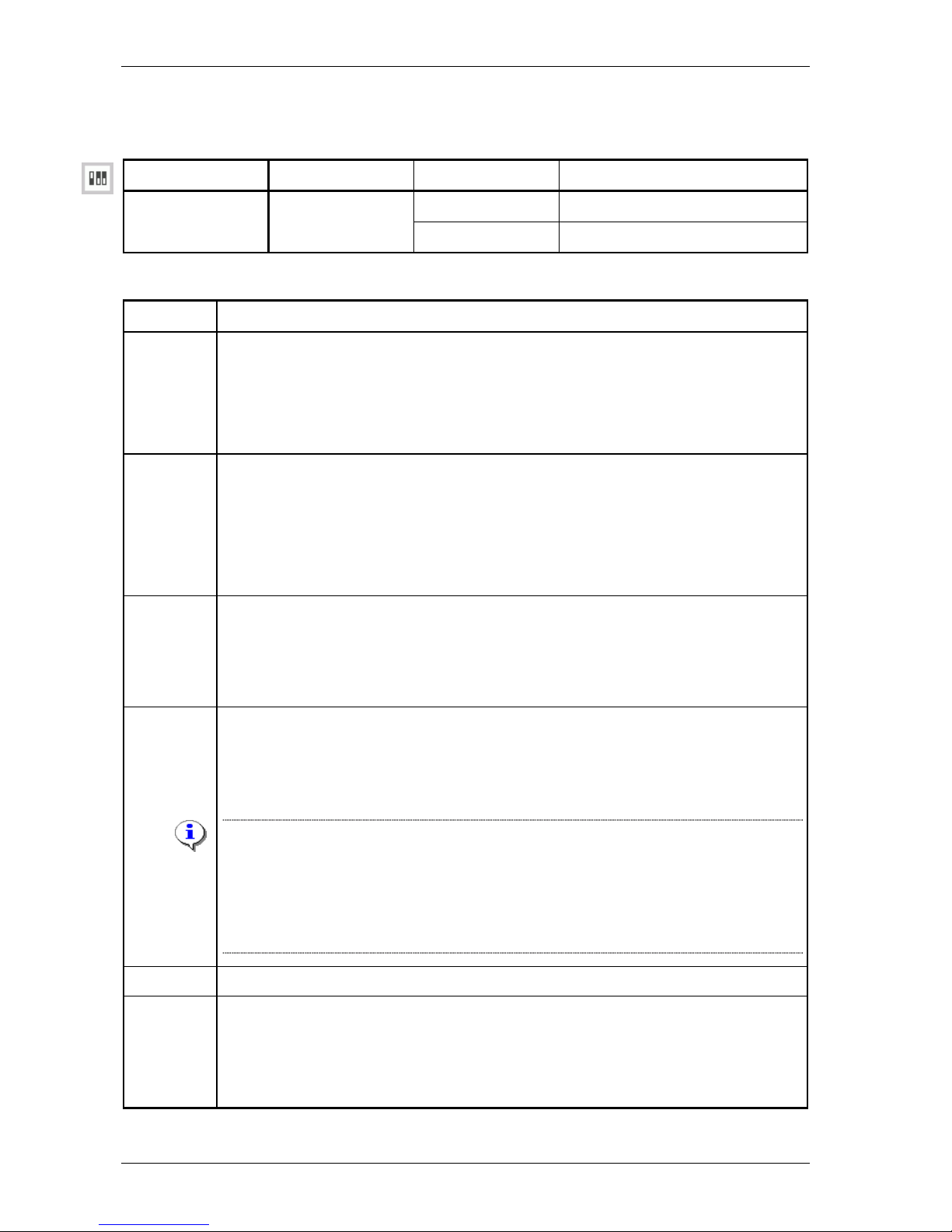
The location of the load default configuration DIP switch is:
DIP switch name DS5 no. Setting Function
on
Normal operation.
load default
configuration
1 (CV-A)
2 (CV-B & TT)
off Load default configuration.
To load the default configuration using the appropriate DIP switch, proceed as follows:
Step Action
1 In case of a …
• TT, open the housing as described in Section 3.1.4 - Changing DIP switch and strap
settings of the Table Top.
• CV, remove the card from the CN4 card nest as described in Section 3.2.5 -
Changing DIP switch and strap settings of the Card Version.
2 In case of a …
• TT, set DIP switch bank DS5 position 2 to off. To locate this DIP switch bank, refer to
Section 3.1.1 - Location of the DIP switches and straps on the Table Top.
• CV, set DIP switch bank DS5 position 1 (for converter A) and / or 2 (for converter B)
to off. To locate this DIP switch bank, refer to Section 3.2.1 - Location of the DIP
switches on the Card Version.
3 In case of a …
• TT, close the housing without fastening the screws.
• CV, insert the card in the CN4 card nest without fastening the screws.
⇒ The Crocus CNV reboots and loads the default configuration.
4 Activate the loaded default configuration:
1. Open a TMA session on the Crocus CNV (refer to Section 4.2 - Connecting to a
Crocus CNV with TMA).
(✱)
2. Execute the Activate Configuration command.
(✱)
If you are performing this load default configuration procedure because you
accidentally made a configuration error, you have the possibility to retrieve this
erroneous configuration before executing the Activate Configuration command. In that case
you do not have to reconfigure the complete device again, but you only have to correct
the error in question. Retrieve the erroneous configuration by executing the Load saved
configuration command.
5 Reset the corresponding DIP switch to on. Refer to step 2.
6 In case of a …
• TT, close the housing.
• CV, insert the card in the CN4 card nest.
⇒ The Crocus CNV reboots in normal operation mode.
Page 67
Crocus CNV Step-by-step configuration
User manual 57
5.2.2 The Load Default Configuration action in TMA
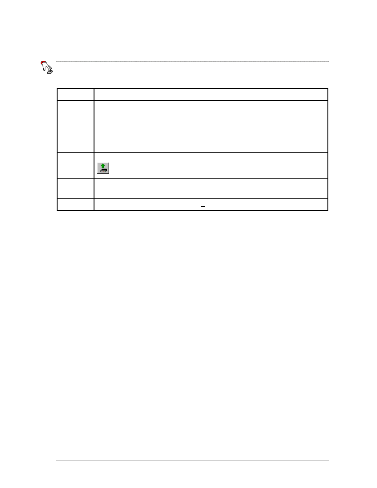
The location of the Load Default Configuration action in the Crocus CNV containment tree is:
crocusIfConv<2m/Nx64><Tt/Cv>/Load Default Configuration
To load the default configuration, proceed as follows:
Step Action
1
In the TMA window, select the top object crocusIfConv<2m/Nx64><Tt/Cv> and the group
Configuration.
2
In the action window of TMA, click the left mouse button on Load Default Configuration so
that this action is selected.
3 Press the right mouse button and select Execute.
4 To see the default configuration, press the Retrieve all attributes from device button
.
5
In the action window of TMA, click the left mouse button on Activate Configuration so that
this action is selected.
6 Press the right mouse button and select Execute.
Page 68

Step-by-step configuration Crocus CNV
58 User manual
5.3 Configuring the clocking mode
This section explains how to configure the clocking mode on the Crocus CNV. The following table gives
an overview of this section.
Section Title Page
5.3.1 The clocking attributes in TMA 59
5.3.2 The different clocking modes 60
5.3.3 The presence of the external clock signal 61
5.3.4 Schematic overview of the different clocking modes 62
5.3.5 Special points of interest concerning clocking on the X21 interface 64
Page 69
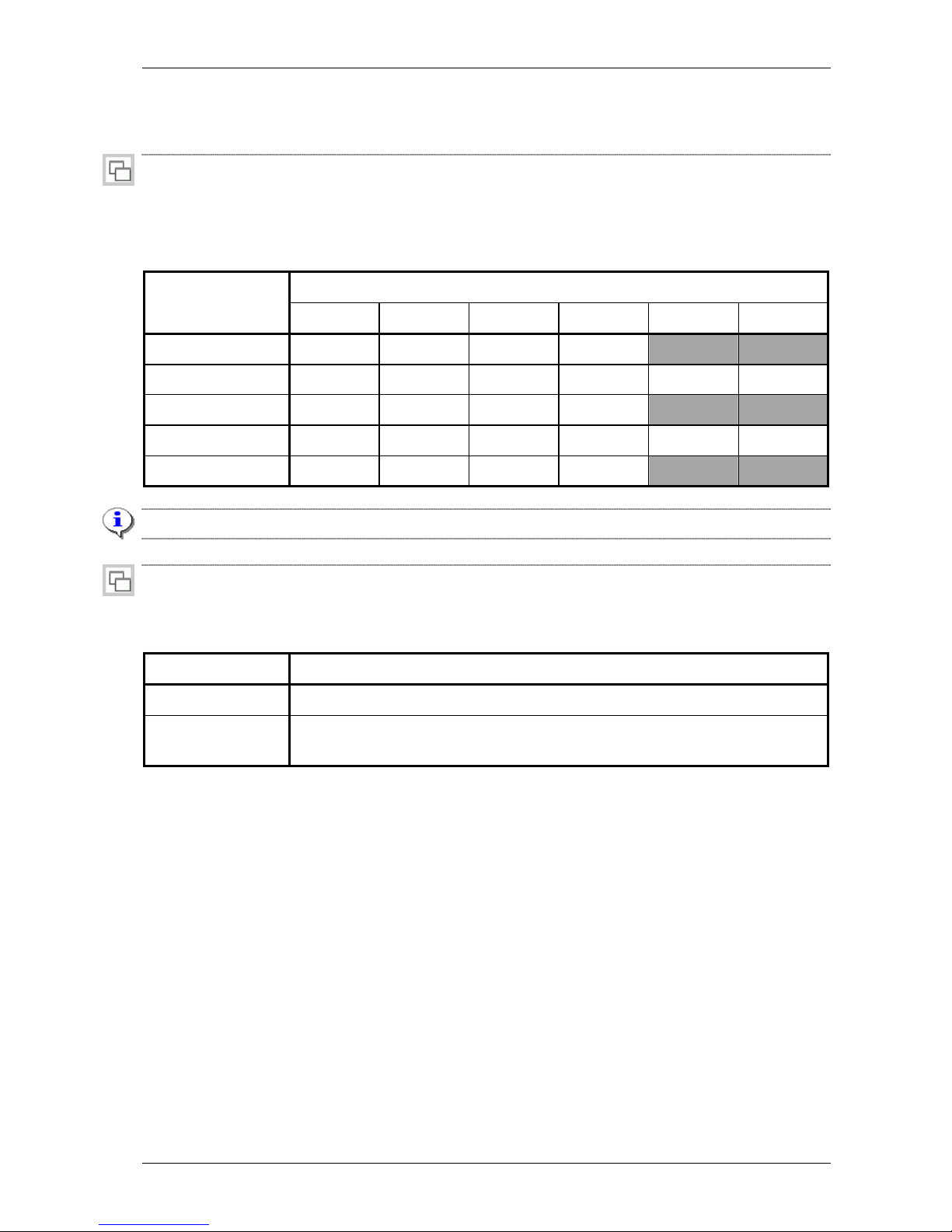
Crocus CNV Step-by-step configuration
User manual 59
5.3.1 The clocking attributes in TMA
Use the following two attributes to select a clocking mode.
crocusIfConv<2m/Nx64><Tt/Cv>/<dteInterface>/txClk default: <interface dependent>
Use this attribute to select the clocking mode of the DTE interface its transmit clock.
The following table gives an overview of the different clocking modes. It also indicates which clocking
modes are supported on which DTE interfaces.
DTE interface Tx clock mode
V35 V36 RS530 X21 Bridge Router
internalPreferred
X X X X
internalAlternative
X X X X X X
slaveRcvPreferred
X X X X
slaveRcvAlternative
X X X X
X X
external
X X X X
The default clocking mode is indicated in bold.
crocusIfConv<2m/Nx64><Tt/Cv>/<dteInterface>/rxClk default: fromLine
Use this attribute to select the clocking mode of the DTE interface its receive clock. The two possibilities
are:
Rx clock mode Description
fromLine
The receive clock of the DTE interface is taken from the G703 line.
slaveTransmit
The receive clock of the DTE interface is taken from the application connected to
the DTE interface.
Page 70
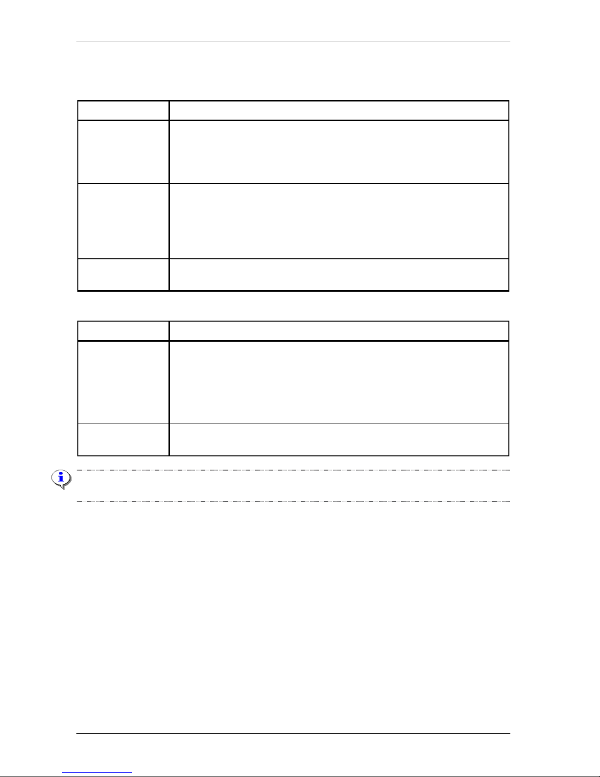
Step-by-step configuration Crocus CNV
60 User manual
5.3.2 The different clocking modes
This section explains the different clocking modes. The following table gives an overview:
Clocking mode Description
internal The Crocus CNV generates the transmit clock signal and sends it to the
application via the TxClk circuit (circuit 114).
Internal clocking can be selected in combination with preferred or alternative
clocking. See below.
slave receive The transmit clock signal is derived from the received line data. This
reconstructed clock signal is sent to the application via the TxClk circuit (circuit
114).
Slave receive clocking can be selected in combination with preferred or
alternative clocking. See below.
external The application generates the transmit clock signal and sends it to the Crocus
CNV via the ExtTxClk circuit (circuit 113).
Internal and slave receive clocking can be selected in combination with preferred or alternative clocking:
Clocking mode Description
preferred The application loops back the output of the TxClk circuit (circuit 114) to the
ExtTxClk circuit (circuit 113). This guarantees an optimal phase relationship
between the transmitted data and the transmitted clock. This because the
transmission delays of the TxD circuit (circuit 103) and the ExtTxClk circuit are
exactly the same, since the outputs of both circuits originate in the application
and are fed into the Crocus CNV.
alternative This does not require the TxClk (circuit 114) to ExtTxClk (circuit 113) loop-back.
In this case the clock is looped back within the Crocus CNV itself.
It may be necessary to use preferred clocking when delays are introduced in the communication between
the DTE and the Crocus CNV. Delays may occur in case of long interconnection cables.
Page 71

Crocus CNV Step-by-step configuration
User manual 61
5.3.3 The presence of the external clock signal
The presence or absence of an external clock signal may influence the clocking mode that is actually
chosen by the Crocus CNV. This section explains how.
All interfaces supporting the external clock signal, regularly check the presence of this external clock
signal. The following table clarifies what happens when no external clock signal is present or when it is
lost:
If the Crocus CNV is
configured in …
and if the external clock signal is not present or if it is lost,
a preferred clocking mode, then the Crocus CNV automatically switches to alternative clocking
mode.
If at a certain moment the external clock signal (re)appears, the Crocus
CNV switches (back) to the preferred clocking mode.
external clocking mode, then the Crocus CNV automatically switches to internal alternative
clocking mode.
If at a certain moment the external clock signal (re)appears, the Crocus
CNV switches (back) to external clocking mode.
Page 72
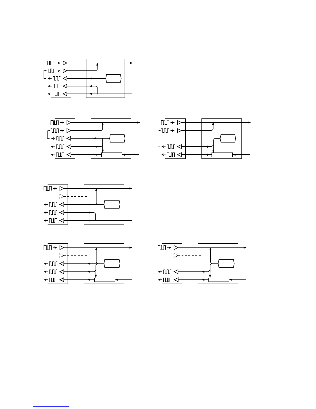
Step-by-step configuration Crocus CNV
62 User manual
5.3.4 Schematic overview of the different clocking modes
The following figures give a schematic overview of all the clocking possibilities:
internalPreferred / fromLine clocking
internalPreferred / slaveTransmit clocking for other
interfaces
internalPreferred / slaveTransmit clocking for X21
interfaces
internalAlternative / fromLine clocking
internalAlternative / slaveTransmit clocking for other
interfaces
internalAlternative / slaveTransmit clocking for X21
interfaces
clock
generation
Tx
Rx
TxD
ExtTxClk
TxClk
RxClk
RxD
DTE DCE G703
Tx
Rx
TxD
X
S
RxD
DTE DCE G703
Retiming buffer
clock
generation
Tx
Rx
TxD
ExtTxClk
TxClk
RxClk
RxD
DTE DCE line
clock
generation
Tx
Rx
TxD
ExtTxClk
TxClk
RxClk
RxD
DTE DCE G703
clock
generation
Retiming buffer
Tx
Rx
TxD
X
S
RxD
DTE DCE G703
clock
generation
Retiming buffer
Tx
Rx
TxD
ExtTxClk
RxClk
RxD
DTE DCE G703
Retiming buffer
clock
generation
TxClk
Page 73
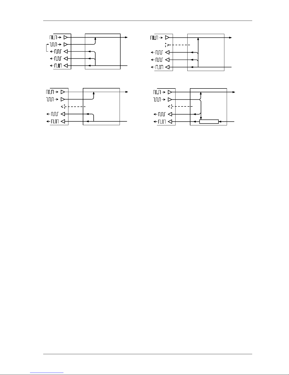
Crocus CNV Step-by-step configuration
User manual 63
slaveRcvPreferred / <any value> clocking
slaveRcvAlternative / <any value> clocking
external / fromLine clocking
external / slaveTransmit clocking
Tx
Rx
TxD
ExtTxClk
TxClk
RxClk
RxD
DTE DCE G703
Tx
Rx
TxD
ExtTxClk
TxClk
RxClk
RxD
DTE DCE G703
Tx
Rx
TxD
ExtTxClk
TxClk
RxClk
RxD
DTE DCE G703
Tx
Rx
TxD
ExtTxClk
RxClk
RxD
DTE DCE G703
Retiming buffer
TxClk
Page 74

Step-by-step configuration Crocus CNV
64 User manual
5.3.5 Special points of interest concerning clocking on the X21 interface
The following are some special points of interest concerning clocking on the X21 interface:
• In internal clocking modes, the S clock is the transmit clock. There is always a retiming buffer in the
receive direction (slave transmit), independent of the rxClk attribute value. The receive data is clocked
out with the internal clock.
• In slave receive clocking modes, the transmit and receive clocks are the same. Hence, there is no
difference with other interfaces.
• In external clocking mode, the S clock is the receive clock.
• It is possible to invert the transmit sample clock on the X21 interfaces. In case of alternative clocking
modes, inversion solves the possible problem of too long delays on the transmit data (from DTE to
DCE) in comparison to the transmit clock (from DCE to DTE). The inversion can be done by means of
DIP switches (refer to Section 3.2.3 - DIP switches of the Card Version).
Page 75
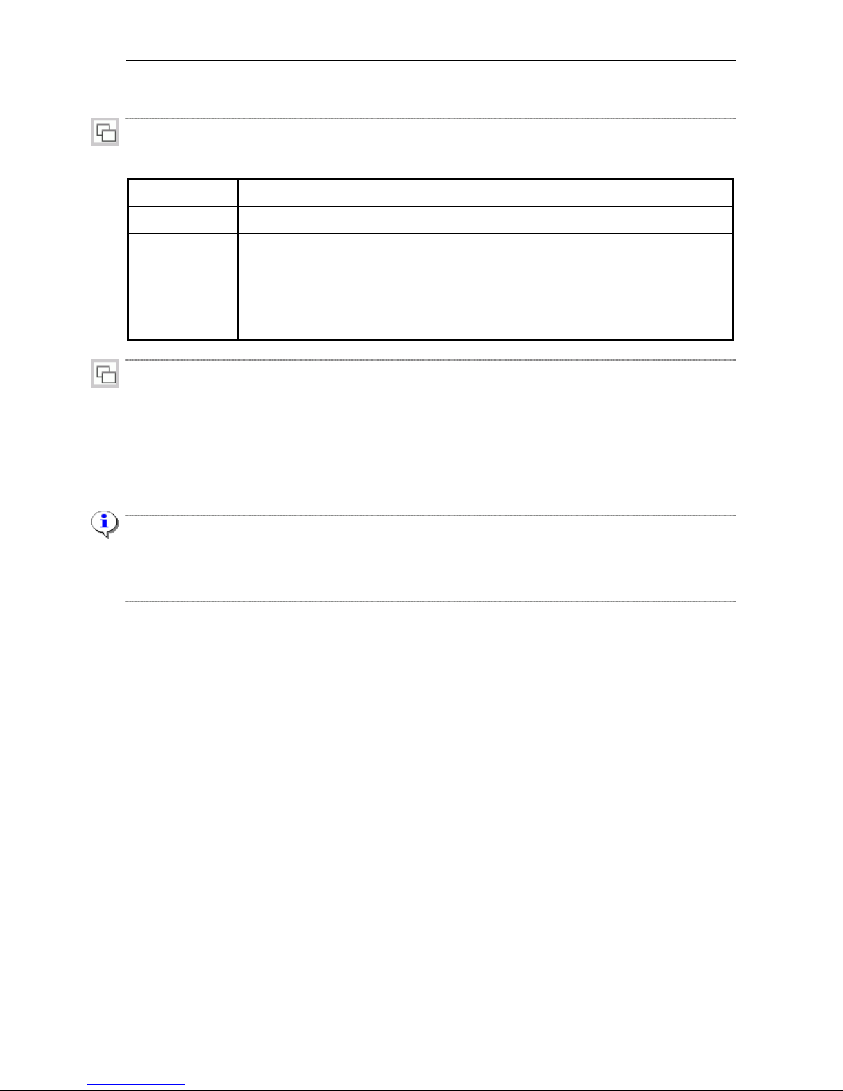
Crocus CNV Step-by-step configuration
User manual 65
5.4 Configuring the onboard G703 interface
crocusIfConv<2m/Nx64><Tt/Cv>/g703OnBoard/coding default: HDB3
Use the coding attribute to set the G703 interface encoding mode. Two encoding modes are available:
Value Description
AMI
Alternate Mark Inversion is a bipolar code with no zero substitution.
HDB3
High Density Bipolar 3 is a modified bipolar code.
With HDB3 encoding, more than three consecutive zeroes occurring in the data are
replaced by a substitution word. This to ensure a high pulse density. Therefore,
data links using the HDB3 code can carry data patterns with a low 1 density. Most
of the G703 applications use HDB3 encoding.
crocusIfConv<2m/Nx64><Tt/Cv>/g703OnBoard/longHaul default: enabled
The onboard G703 interface is equipped with a driver. This enables you to cover long distances. The
driver can be enabled or disabled.
The distances that can be covered are in the order of:
• 2.5 km using a cable with a diameter of 0.6 mm
• 1.25 km using a cable with a diameter of 0.4 mm.
Important remark
On a Crocus 2M CNV CV and on a Crocus Nx64 CNV CV in unframed mode, it is not possible to start an
RDL test or receive a DL test from the remote side when the device is strapped in short haul (i.e. longHaul
= disabled). However, it is possible to start a DL test directly on the device itself.
Page 76

Step-by-step configuration Crocus CNV
66 User manual
crocusIfConvNx64<Tt/Cv>/g703OnBoard/crc4Insertion default: enabled
This attribute is only present on the Crocus Nx64 CNV.
Use the crc4Insertion attribute to enable or disable the cyclic redundancy check (CRC). If you enable this
attribute, a CRC is inserted in time slot 0 of the G.704 framed data stream. This CRC is used to check the
data integrity on the G.703 connection.
crocusIfConvNx64<Tt/Cv>/g703OnBoard/timeSlots default: 00000000000000000000000000000001
This attribute is only present on the Crocus Nx64 CNV.
Use the timeSlots attribute to …
• set the G703 interface to unframed or framed mode.
• allocate time slots in case the G703 interface is in framed mode.
Unframed and framed mode
The following table explains the difference between unframed and framed mode.
Mode Description
unframed
(transparent)
In unframed mode, a 2 Mbps data stream is sent transparently over the line.
framed
(G.704 framing)
In framed mode, up to 31 time slots each containing a 64 kbps data stream can be
sent over the line. Each 64 kbps time slot can be enabled or disabled. Time slot 0 is
reserved for synchronisation and signalling.
Selecting unframed mode
Select unframed mode by setting time slot TS0 to 1 (enabled). The value of the time slots TS1 up to TS31
is irrelevant.
Selecting framed mode and allocating time slots
Select framed mode and allocate time slots as follows:
1. Set time slot TS0 to 0 (disabled) to enable G.704 framing.
2. Allocate the desired time slots by setting them to value 1 (enabled).
Page 77

Crocus CNV Step-by-step configuration
User manual 67
5.5 Configuring the interface specific attributes
This section explains the most important interface specific attributes. The following table gives an
overview of this section:
Section Title Page
5.5.1 Configuring the RTS control (RS530, V35, V36) 68
5.5.2 Configuring the LAN filter (Bridge) 69
Page 78

Step-by-step configuration Crocus CNV
68 User manual
5.5.1 Configuring the RTS control (RS530, V35, V36)
crocusIfConv<2m/Nx64><Tt/Cv>/<dteInterface>/rtsControl default: external
Use the rtsControl attribute to define which device will activate the RTS signal.
Normal operation requires the RTS signal (circuit 105) to be active before the Crocus CNV activates its
data transfer state, as indicated by the CTS signal (circuit 106). Therefore, make sure the RTS signal is
activated either by the application or by the Crocus CNV.
If RTS control is
set to …
the RTS signal is
activated by …
Use this setting in case …
external the application. the application has to be in command of the RTS signal.
internal the Crocus CNV. the application is not able to activate the RTS signal.
Page 79
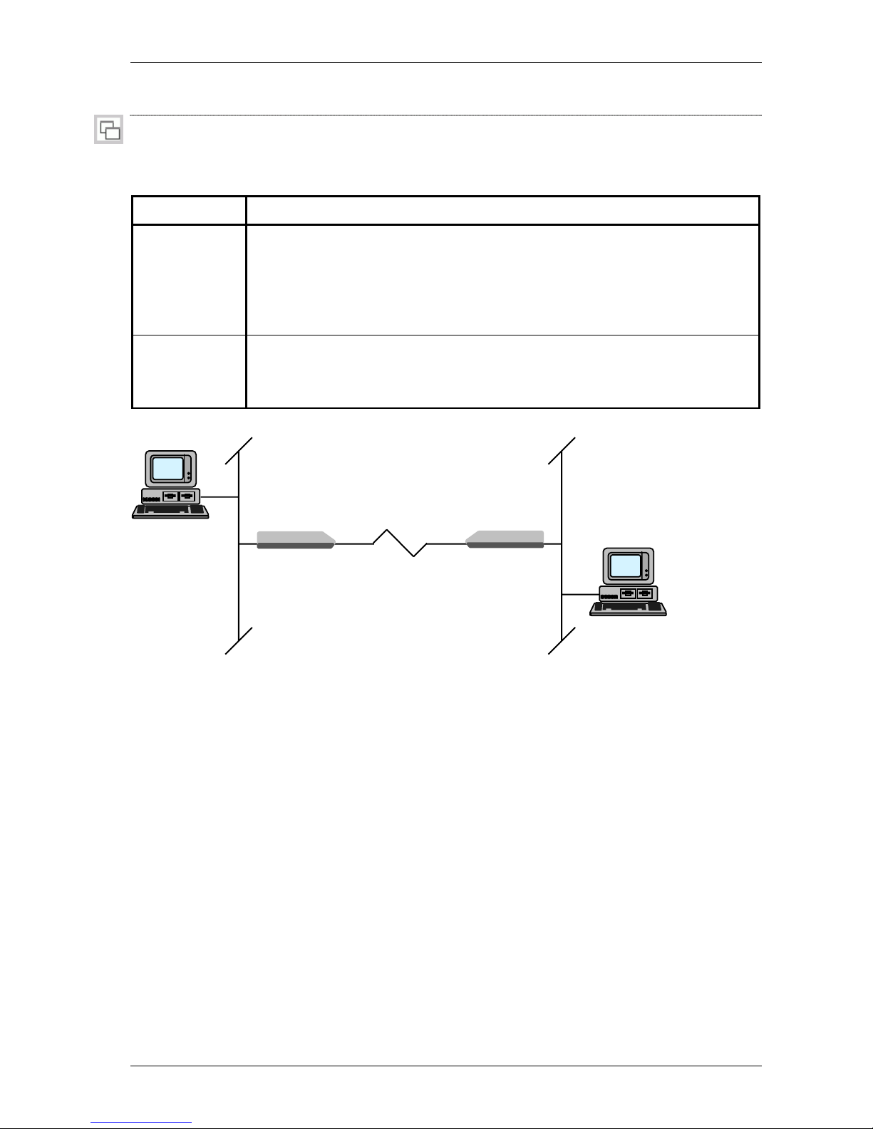
Crocus CNV Step-by-step configuration
User manual 69
5.5.2 Configuring the LAN filter (Bridge)
crocusIfConv<2m/Nx64><Tt/Cv>/bridge/IanFilter default: enabled
Use the lanFilter attribute to enable or disable the filter functionality of the bridge. The lanFilter attribute can
be set to:
Value Description
enabled
The bridge acts as a filter.
Refer to the figure below. Data coming from network 1, will only be let through by
the bridge if this data has a destination address outside network 1 or a multicast or
broadcast address. The bridge filters the data and decreases the traffic on the serial
line.
disabled
The bridge acts as a repeater.
Refer to the figure below. All the data which originates from network 1 will be let
through to network 2. Even if the data is not destined for that network.
The following figure depicts a bridge set-up:
Figure 5.1: Bridge functionality
PC1
network 1 network 2
modem +
bridge
modem +
bridge
PC2
Page 80

Step-by-step configuration Crocus CNV
70 User manual
5.6 Configuring the management attributes
This section explains the management attributes of the Crocus CNV. These attributes allow you to make
all the devices in your network accessible for management from one central location.
First this section gives you some rules of thumb and remarks concerning the management of the Crocus
CNV in a network. Then it explains the attributes that have an impact on the management of the Crocus
CNV.
The following table gives an overview of this section:
Section Title Page
5.6.1 Rules of thumb and remarks concerning management 71
5.6.2 Selecting the purpose of the control connector 72
Page 81

Crocus CNV Step-by-step configuration
User manual 71
5.6.1 Rules of thumb and remarks concerning management
The following lists some rules of thumb concerning the management of OneAccess devices in a network:
• Make sure there is only one path towards the management system. Else you might get unexpected
results (e.g. devices that do not answer to polling, answer of several devices at once when polling one
device, etc.).
• Once your network starts to become complex on management level (i.e. more than just in-line
connections as depicted in Section 6.5 Management configuration attributes), you are advised to use
absolute addressing instead of relative addressing.
In practice, it is best to use absolute addressing when you configure one of the attributes listed below
as follows:
− ctrlPortProtocol attribute to management.
• If you use a router interface in the Crocus CNV, then you are advised to set the ctrlPortProtocol attribute
to management. Else you might be unable to manage the router interface.
• The Crocus CNV is not a true multi-device (a multi-device is a device that incorporates several
devices on one card, such as the Crocus SHDSL CV Twin). However, if a router interface is inserted
in both modular interface slot A and B and the ctrlPortProtocol attribute is set to …
− console, then the router interface in interface slot B is linked to “modem B”. In practice, this means
that when using e.g. a management concentrator you have to specify modem B in your exit port
settings.
− management, then the router interface in interface slot B is linked to “modem A”. In practice, this
means that when using e.g. a management concentrator you have to specify modem A instead of
modem B in your exit port settings.
• Changing the ctrlPortProtocol attribute causes the Crocus CNV to reboot.
Page 82

Step-by-step configuration Crocus CNV
72 User manual
5.6.2 Selecting the purpose of the control connector
crocusIfConvAdmCv/management/ctrlPortProtocol default: console
The setting of the ctrlPortProtocol attribute depends on what purpose the control connector of the Crocus
CNV has to serve. This is explained in the following table:
Value Description
management
Select this value if you want to connect the control connector of the Crocus CNV to
…
• a management concentrator (e.g. the Orchid 1003 LAN or 1035 Orchid) for
management purposes.
• the control connector of another OneAccess device using a crossed cable (i.e.
they are connected back-to-back) in order to create an extended management
link. For more information on extended management links, refer to Section 6.5
Management configuration attributes.
When connecting the control connector of the Crocus CNV to a COM port of your
computer, you can still open a TMA session on the Crocus CNV. You can however
not open a CLI or ATWIN session.
console
Select this value if you want to connect the control connector of the Crocus CNV to
a COM port of your computer in order to manage the Crocus CNV using TMA, CLI
or ATWIN.
Page 83

Crocus CNV Step-by-step configuration
User manual 73
5.7 Activating the configuration
Once the basic configuration of the Crocus CNV is made, it has to be activated. Do this by pressing the
Send all attributes to device button in TMA:
If you experience problems of any kind, you can always consult the status, performance and alarm
attributes in order to determine the problem. For more information on these attributes, refer to the
reference manual.
Page 84

Crocus CNV
74 Reference manual
Reference manual
Page 85

Crocus CNV
Reference manual 75
Page 86

Configuration attributes Crocus CNV
76 Reference manual
6 Configuration attributes
This chapter discusses the configuration attributes of the Crocus CNV. The following table gives an
overview of this chapter.
Section Title Page
6.1 Configuration attribute overview 77
6.2 General configuration attributes 78
6.3 G703 onboard configuration attributes 85
6.4 Interface configuration attributes 89
6.5 Management configuration attributes 93
Page 87

Crocus CNV Configuration attributes
Reference manual 77
6.1 Configuration attribute
overview
> crocusIfConv<2m/Nx64><Tt/Cv>
sysName
sysContact
sysLocation
bootFromFlash
security
alarmMask
alarmLevel
alarmContactHighMask
(1)
alarmContactLowMask
(1)
remoteAlarmMask
(4)
Action: Activate Configuration
Action: Load Saved Configuration
Action: Load Default Configuration
Action: Cold Boot
>> g703OnBoard
coding
tests
alarmMask
alarmLevel
alarmContactHighMask
(1)
alarmContactLowMask
(1)
remoteAlarmMask
(4)
longHaul
crc4Insertion
(2)
timeSlots
(2)
name
aisDetection
sqTime
sqTreshold
>> rs530, v35, v36
(3)
rtsControl
ctsDelay
tests
alarmMask
alarmLevel
alarmContactHighMask
(1)
alarmContactLowMask
(1)
1
CV only
2
only present on the Crocus Nx64 CNV
3
only present when the corresponding interface is
used
remoteAlarmMask
(4)
txClk
rxClk
>> x21
(3)
alarmMask
alarmLevel
alarmContactHighMask
(1)
alarmContactLowMask
(1)
remoteAlarmMask
(4)
txClk
rxClk
>> bridge
(3)
IanFilter
alarmMask
alarmLevel
alarmContactHighMask
(1)
alarmContactLowMask
(1)
remoteAlarmMask
(4)
txClk
rxClk
>> router
(3)
alarmMask
alarmLevel
alarmContactHighMask
(1)
alarmContactLowMask
(1)
remoteAlarmMask
(4)
txClk
rxClk
>> management
cms2Address
consoleNoTrafficTimeout
ctrlPortProtocol
(4)
.
4
TT only
Page 88
Configuration attributes Crocus CNV
78 Reference manual
6.2 General configuration attributes
crocusIfConv<2m/Nx64><Tt/Cv>/sysName default: <empty>
This is a field where you can assign a name to the Crocus CNV. The field has a limit of 64 characters.
This is a SNMP MIB2 parameter.
crocusIfConv<2m/Nx64><Tt/Cv>/sysContact default: <empty>
This is a field where you can fill in the name of a contact person together with information on how to
contact this person. The field has a limit of 64 characters.
This is a SNMP MIB2 parameter.
crocusIfConv<2m/Nx64><Tt/Cv>/sysLocation default: <empty>
This is a field where you can fill in the physical location of the Crocus CNV. The field has a limit of 64
characters.
This is a SNMP MIB2 parameter.
crocusIfConv<2m/Nx64><Tt/Cv>/bootFromFlash default: auto
The Crocus CNV has two flash memory banks. Each flash memory can contain a complete software
version, but only one can be active. You can choose from the following settings:
Value If you boot the Crocus CNV then …
flash1
the first flash memory bank is activated.
flash2
the second flash memory bank is activated.
auto
the Crocus CNV automatically chooses the flash memory bank containing the most
recent firmware, by comparing the firmware version numbers.
For a Crocus CNV CV, the bootFromFlash attribute only works on converter A. Although the bootFromFlash
attribute is also visible in the containment tree of converter B, its setting is ignored. Both converter A and
B use the same firmware.
Page 89
Crocus CNV Configuration attributes
Reference manual 79
crocusIfConv<2m/Nx64><Tt/Cv>/security default: <empty>
In order to avoid unauthorised access to the network and the Crocus CNV, you can create a list of
passwords with associated access levels. The security attribute contains the following elements:
Element Description Default value
password
The password is a string of maximum 10 characters.
<empty>
accessRights
This attribute represents the access levels assigned to a
password. It is a bit string whereof each bit corresponds to an
access level. The table below describes the different access
levels.
111
Element Description
ReadAccess
A password that includes this access
level allows you to read all attributes,
except security attributes.
on
WriteAccess
A password that includes this access
level allows you to change all attributes,
except security attributes. Moreover, the
security attributes cannot be read.
on
SecurityAccess
A password that includes this access
level allows you to read and change
security attributes. The Crocus CNV has
the following security attributes:
• crocusIfConv<2m/Nx64><Tt/Cv>/security
on
If no passwords are created, everybody has complete access.
If you define at least one password, it is impossible to access the Crocus CNV with TMA if you do not
enter the correct password.
If you create a list of passwords, you should create at least one with write and security access. If not, you
will be unable to make configuration and password changes after activation of the new configuration.
Page 90

Configuration attributes Crocus CNV
80 Reference manual
Correcting the security table
If you forgot your password or you forgot to create one with write and security access, then you can set
the Load Default Configuration DIP switch. As a result, the Crocus CNV reboots in its default
configuration. You can then retrieve the erroneous configuration and correct it.
To correct the security table, proceed as follows:
Step Action
1 Remove the Crocus CNV from the CN4 card nest as described in Section 3.2.5 -
Changing DIP switch and strap settings of the Card Version.
2 Set DIP switch bank DS5 position 1 (for converter A) and / or 2 (for converter B) to off.
To locate this DIP switch bank, refer to Section 3.2.1 - Location of the DIP switches on
the Card Version.
3 Re-insert the Crocus CNV in the CN4 card nest.
⇒ The Crocus CNV reboots and loads the default configuration.
4 Retrieve the erroneous configuration:
1. Open a TMA session on the Crocus CNV (refer to Section 4.2 - Connecting to a
Crocus CNV with TMA).
2. Execute the Load saved configuration command.
3. Correct the error in the security table.
4. Execute the Activate Configuration command.
5 Reset DIP switch bank DS5 position 1 (for converter A) and / or 2 (for converter B) to on.
6 Re-insert the Crocus CNV in the CN4 card nest as described in Section 3.2.5 -
Changing DIP switch and strap settings of the Card Version.
⇒ The Crocus CNV reboots in normal operation mode.
Page 91
Crocus CNV Configuration attributes
Reference manual 81
crocusIfConv<2m/Nx64><Tt/Cv>/alarmMask
The alarmMask attribute enables or disables for each alarm of the corresponding object, whether it is
communicated to the central management system (e.g. HP OpenView
®
) or not.
For more information on …
• alarms in general, refer to Section 9.2 Introducing the alarm attributes.
• the alarms of the crocusIfConv<2m/Nx64><Tt/Cv> object, refer to Section 9.3 - General alarms.
crocusIfConv<2m/Nx64><Tt/Cv>/alarmLevel
With this attribute, a priority level can be assigned to each alarm of the corresponding object. The alarm
level ranges from 0 up to 254, where 0 is the lowest and 254 is the highest priority level.
crocusIfConv<2m/Nx64>Cv/alarmContactHighMask
This attribute is only present on the CV.
The alarmContactHighMask attribute enables or disables for each alarm of the corresponding object,
whether:
• a visual indication is generated (blinking error LED)
• the alarm contacts on the CN4 card nest are driven.
crocusIfConv<2m/Nx64>Cv/alarmContactLowMask
This attribute is only present on the CV.
The alarmContactLowMask attribute enables or disables for each alarm of the corresponding object, whether:
• a visual indication is generated (blinking error LED)
• the alarm contacts on the CN4 card nest are driven.
crocusIfConv<2m/Nx64>Tt/ remoteAlarmMask
This attribute is only present on the TT.
The remoteAlarmMask attribute enables or disables for each alarm of the corresponding object, whether:
• a visual indication is generated (blinking error LED).
• an alarm is sent to the remote Crocus CNV.
By default, all the alarms in the remoteAlarmMask are set to disabled.
Page 92
Configuration attributes Crocus CNV
82 Reference manual
Configuration actions
Three types of configuration are present in the Crocus CNV:
• the non-active configuration
• the active configuration
• the default configuration.
When configuring the Crocus CNV with TMA, as in Chapter 5 - Step-by-step configuration, the following
happens:
Phase Action Result
1 The computer running TMA is connected
to the Crocus CNV.
The non-active configuration is displayed
on the screen.
2 Modifications are made on the non-active
configuration.
These modifications have no immediate
influence on the active configuration
currently used by the Crocus CNV.
3 All necessary modifications are carried out
on the non-active configuration.
Now, the non-active configuration has to
be made active.
4
Execute the Activate Configuration action.
The non-active configuration becomes the
active configuration.
crocusIfConv<2m/Nx64><Tt/Cv>/Activate Configuration
If you execute this action, the editable non-active configuration becomes the active configuration.
To activate a configuration, proceed as follows:
Step Action
1
In the TMA window, select the top object crocusIfConv<2m/Nx64><Tt/Cv> and the group
Configuration.
2
In the action window of TMA, click the left mouse button on Activate Configuration so that
this action is selected.
3 Press the right mouse button and select Execute.
The Activate Configuration action can also be performed with the Send all attributes to device button: .
Page 93
Crocus CNV Configuration attributes
Reference manual 83
crocusIfConv<2m/Nx64><Tt/Cv>/Load Saved Configuration
If you are in the progress of modifying the non-active configuration but made some mistakes, you might
want to revert to the active configuration. If you execute the Load Saved Configuration action, the non-active
configuration is overwritten by the active configuration currently used by the Crocus CNV.
To reload the active configuration, proceed as follows:
Step Action
1
In the TMA window, select the top object crocusIfConv<2m/Nx64><Tt/Cv> and the group
Configuration.
2
In the action window of TMA, click the left mouse button on Load Saved Configuration so that
this action is selected.
3 Press the right mouse button and select Execute.
4 To see the active configuration, press the Retrieve all attributes from device button:
.
crocusIfConv<2m/Nx64><Tt/Cv>/Load Default Configuration
If you install the Crocus CNV for the first time, all configuration attributes are set to their default value. If
the Crocus CNV has already been configured a number of times and you want to reconfigure it starting
from scratch, you can load the default configuration.
To load the default configuration, proceed as follows:
Step Action
1
In the TMA window, select the top object crocusIfConv<2m/Nx64><Tt/Cv> and the group
Configuration.
2
In the action window of TMA, click the left mouse button on Load Default Configuration so
that this action is selected.
3 Press the right mouse button and select Execute.
4 To see the default configuration, press the Retrieve all attributes from device button
.
5
In the action window of TMA, click the left mouse button on Activate Configuration so that
this action is selected.
6 Press the right mouse button and select Execute.
Page 94

Configuration attributes Crocus CNV
84 Reference manual
crocusIfConv<2m/Nx64><Tt/Cv>/Cold Boot
This action will reboot the Crocus CNV while the power stays up (the Crocus CNV also reboots if it is
powered down and up again).
This implies that:
• it checks which firmware to use
• it reads the saved configuration and restarts program execution.
You can use this action, for instance, to activate new firmware.
To perform a cold boot, proceed as follows:
Step Action
1
In the TMA window, select the top object crocusIfConv<2m/Nx64><Tt/Cv> and the group
Configuration, Status, Performance or Alarms.
2
In the action window of TMA, click the left mouse button on Cold Boot so that this action is
selected.
3 Press the right mouse button and select Execute.
⇒ The session between TMA and the Crocus CNV is interrupted.
4 Re-establish a TMA session on the Crocus CNV.
⇒ The Crocus CNV attributes reappear on your screen.
If a Cold Boot is performed on a Crocus CNV CV, both converter A and B reboot.
Page 95
Crocus CNV Configuration attributes
Reference manual 85
6.3 G703 onboard configuration attributes
crocusIfConv<2m/Nx64><Tt/Cv>/g703OnBoard/coding default: HDB3
Use the coding attribute to set the G703 interface encoding mode. Two encoding modes are available:
Value Description
AMI
Alternate Mark Inversion is a bipolar code with no zero substitution.
HDB3
High Density Bipolar 3 is a modified bipolar code.
With HDB3 encoding, more than three consecutive zeroes occurring in the data are
replaced by a substitution word. This to ensure a high pulse density. Therefore,
data links using the HDB3 code can carry data patterns with a low 1 density. Most
of the G703 applications use HDB3 encoding.
crocusIfConv<2m/Nx64><Tt/Cv>/g703OnBoard/tests
Use the tests attribute to enable or disable detection of an RDL test and to set its duration:
Element Description Default value
rdlDetect
When set to disabled, this attribute prevents that a digital loop
can be performed by a remote Crocus CNV on the local Crocus
CNV.
When rdlDetect is disabled, and a remote Crocus CNV initiates an
RDL test, the local Crocus CNV will not go in digital loop.
However, the DTE interface of the remote Crocus CNV will be
clamped and data transfer is interrupted.
enabled
testDuration
Some tests cause an interruption of the normal data transfer.
Therefore, all tests are automatically terminated after a time-out
period which is specified with the testDuration attribute.
The time-out ranges from 00h 00m 01s up to 18h 12m 15s. Entering
00h 00m 00s disables the time-out period.
03m 00s
Page 96
Configuration attributes Crocus CNV
86 Reference manual
crocusIfConv<2m/Nx64><Tt/Cv>/g703OnBoard/alarmMask
The alarmMask attribute enables or disables for each alarm of the corresponding object, whether it is
communicated to the central management system (e.g. HP OpenView
®
) or not.
For more information on …
• alarms in general, refer to Section 9.2 Introducing the alarm attributes.
• the alarms of the g703OnBoard object, refer to Section 9.4 - G703 onboard alarms.
crocusIfConv<2m/Nx64><Tt/Cv>/g703OnBoard/alarmLevel
With this attribute, a priority level can be assigned to each alarm of the corresponding object. The alarm
level ranges from 0 up to 254, where 0 is the lowest and 254 is the highest priority level.
crocusIfConv<2m/Nx64>Cv/g703OnBoard/alarmContactHighMask
This attribute is only present on the CV.
The alarmContactHighMask attribute enables or disables for each alarm of the corresponding object,
whether:
• a visual indication is generated (blinking error LED)
• the alarm contacts on the CN4 card nest are driven.
crocusIfConv<2m/Nx64>Cv/g703OnBoard/alarmContactLowMask
This attribute is only present on the CV.
The alarmContactLowMask attribute enables or disables for each alarm of the corresponding object, whether:
• a visual indication is generated (blinking error LED)
• the alarm contacts on the CN4 card nest are driven.
crocusIfConv<2m/Nx64><Tt/Cv>/g703OnBoard/longHaul default: enabled
The onboard G703 interface is equipped with a driver. This enables you to cover long distances. The
driver can be enabled or disabled.
The distances that can be covered are in the order of:
• 2.5 km using a cable with a diameter of 0.6 mm
• 1.25 km using a cable with a diameter of 0.4 mm.
Important remark
On a Crocus 2M CNV CV and on a Crocus Nx64 CNV CV in unframed mode, it is not possible to start an
RDL test or receive a DL test from the remote side when the device is strapped in short haul (i.e. longHaul
= disabled). However, it is possible to start a DL test directly on the device itself.
Page 97

Crocus CNV Configuration attributes
Reference manual 87
crocusIfConvNx64<Tt/Cv>/g703OnBoard/crc4Insertion default: enabled
This attribute is only present on the Crocus Nx64 CNV.
Use the crc4Insertion attribute to enable or disable the cyclic redundancy check (CRC). If you enable this
attribute, a CRC is inserted in time slot 0 of the G.704 framed data stream. This CRC is used to check the
data integrity on the G.703 connection.
crocusIfConvNx64<Tt/Cv>/g703OnBoard/timeSlots default: 00000000000000000000000000000001
This attribute is only present on the Crocus Nx64 CNV.
Use the timeSlots attribute to …
• set the G703 interface to unframed or framed mode.
• allocate time slots in case the G703 interface is in framed mode.
Unframed and framed mode
The following table explains the difference between unframed and framed mode.
Mode Description
unframed
(transparent)
In unframed mode, a 2 Mbps data stream is sent transparently over the line.
framed
(G.704 framing)
In framed mode, up to 31 time slots each containing a 64 kbps data stream can be
sent over the line. Each 64 kbps time slot can be enabled or disabled. Time slot 0 is
reserved for synchronisation and signalling.
Selecting unframed mode
Select unframed mode by setting time slot TS0 to 1 (enabled). The value of the time slots TS1 up to TS31
is irrelevant.
Selecting framed mode and allocating time slots
Select framed mode and allocate time slots as follows:
1. Set time slot TS0 to 0 (disabled) to enable G.704 framing.
2. Allocate the desired time slots by setting them to value 1 (enabled).
Page 98
Configuration attributes Crocus CNV
88 Reference manual
crocusIfConv<2m/Nx64><Tt/Cv>/g703OnBoard/name default: <empty>
Use the name attribute to assign an administrative name to the interface.
crocusIfConv<2m/Nx64><Tt/Cv>/g703OnBoard/aisDetection default: enabled
Use this attribute to enable or disable the detection of the Alarm Indication Signal.
crocusIfConv<2m/Nx64><Tt/Cv>/g703OnBoard/sqTime default: 00000d 00h 01m 00s
Use this attribute to set the signal quality time. This is the period (in days, hours, minutes and seconds)
during which the signal quality threshold is measured.
If the sqThreshold value, i.e. the number of errored seconds, is exceeded within the sqTime, then a signal
quality (sq) alarm is generated. For example, if 10 (default) or more errored seconds occur within 1
minute (default), then a signal quality alarm is generated.
The sqTime value ranges from 00000d 00h 00m 00s up to 24855d 03h 14m 07s.
crocusIfConv<2m/Nx64><Tt/Cv>/g703OnBoard/sqTreshold default: 32 bits
Use this attribute to set the signal quality threshold. This is the number of errored seconds for which a
signal quality alarm is generated.
If the sqThreshold value, i.e. the number of errored seconds, is exceeded within the sqTime, then a signal
quality (sq) alarm is generated. For example, if 10 (default) or more errored seconds occur within 1 minute
(default), then a signal quality alarm is generated.
The sqThreshold value ranges from 0 up to 65535.
crocusIfConv<2m/Nx64>Tt/ remoteAlarmMask
This attribute is only present on the TT.
The remoteAlarmMask attribute enables or disables for each alarm of the corresponding object, whether:
• a visual indication is generated (blinking error LED).
• an alarm is sent to the remote Crocus CNV.
By default, all the alarms in the remoteAlarmMask are set to disabled.
Page 99

Crocus CNV Configuration attributes
Reference manual 89
6.4 Interface configuration attributes
This section discusses the configuration attributes of the different DTE interfaces. The following table
gives an overview of this section.
Section Title Page
6.4.1 General interface configuration attributes 90
6.4.2 RS530, V35 and V36 interface configuration attributes 91
6.4.3 Bridge interface configuration attributes 92
Because some of the interface configuration attributes are present on every interface, they are discussed
in a general section. All other sections discuss the interface specific attributes.
Page 100
Configuration attributes Crocus CNV
90 Reference manual
6.4.1 General interface configuration attributes
crocusIfConv<2m/Nx64><Tt/Cv>/<dteInterface>/alarmMask
The alarmMask attribute enables or disables for each alarm of the corresponding object, whether it is
communicated to the central management system (e.g. HP OpenView
®
) or not.
For more information on …
• alarms in general, refer to Section 9.2 Introducing the alarm attributes.
• the alarms of the <dteInterface> object, refer to Section 9.5 - Interface alarms.
Note that the underlying alarms may differ for each interface.
crocusIfConv<2m/Nx64><Tt/Cv>/<dteInterface>/alarmLevel
With this attribute, a priority level can be assigned to each alarm of the corresponding object. The alarm
level ranges from 0 up to 254, where 0 is the lowest and 254 is the highest priority level.
crocusIfConv<2m/Nx64>Cv/<dteInterface>/alarmContactHighMask
This attribute is only present on the CV.
The alarmContactHighMask attribute enables or disables for each alarm of the corresponding object,
whether:
• a visual indication is generated (blinking error LED)
• the alarm contacts on the CN4 card nest are driven.
crocusIfConv<2m/Nx64>Cv/<dteInterface>/alarmContactLowMask
This attribute is only present on the CV.
The alarmContactLowMask attribute enables or disables for each alarm of the corresponding object, whether:
• a visual indication is generated (blinking error LED)
• the alarm contacts on the CN4 card nest are driven.
crocusIfConv<2m/Nx64><Tt/Cv>/<dteInterface>/txClk default: <interface dependent>
Use this attribute to select the clocking mode of the DTE interface its transmit clock. For more information
on clocking, refer to Section 5.3 - Configuring the clocking mode.
crocusIfConv<2m/Nx64><Tt/Cv>/<dteInterface>/rxClk default: fromLine
Use this attribute to select the clocking mode of the DTE interface its receive clock. For more information
on clocking, refer to Section 5.3 - Configuring the clocking mode.
• crocusIfConv<2m/Nx64>Tt/ remoteAlarmMask
This attribute is only present on the TT.
The remoteAlarmMask attribute enables or disables for each alarm of the corresponding object, whether:
• a visual indication is generated (blinking error LED).
• an alarm is sent to the remote Crocus CNV.
By default, all the alarms in the remoteAlarmMask are set to disabled.
 Loading...